
Submitted:
14 October 2024
Posted:
14 October 2024
You are already at the latest version
Abstract
We implement a simulation environment on top of NetSquid that is specifically designed for estimating the end-to-end fidelity across a path of quantum repeaters or quantum switches. The switch model includes several generalizations which are not currently available in other tools, and are useful for gaining insight into practical and realistic quantum network engineering problems: an arbitrary number of memory registers at the switches, simplicity in including entanglement distillation mechanisms, arbitrary switching topologies, and more accurate models for the depolarization noise. An illustrative case study is presented, namely a comparison in terms of performance between a repeater chain where repeaters can only swap sequentially, and a single switch equipped with multiple memory registers, able to handle multiple swapping requests.
Keywords:
Quantum networks
; entanglement distribution
; resource allocation
; simulation
1. Introduction
Long-distance quantum communications and distributed quantum computing tasks necessitate efficient entanglement distribution among the parties to be feasible at practical scale in order to process quantum information in better and more capable ways than those achievable with classical communications [1,2,3]. Also, high-rate entanglement distribution is key for realizing information-theoretical secure communications [4]. However, long-distance distribution of entangled states requires the use of quantum repeaters (QR) or quantum switches (QS) as intermediate devices to propagate sequentially the link-level entanglement [5,6], so that end-to-end entangled (EEE) states between two arbitrary nodes are created. Functionally, a QR and a QS are similar but QRs are simpler, since they are basically two-port devices that extend a linear chain of links, while QSs could in principle allow for more general internal quantum connections from an input to an output port [7]. As in classical networking, QRs would enable the construction of general physical interconnection topologies for a quantum network.
Controlling the delay, throughput, and quality (in fidelity, a quantitative measure of entanglement) of a quantum network based on repeaters or switches is thus a fundamental challenge for practical applications [8,9]. Different analytical models are being developed for elucidating the performance of quantum networks under a variety of assumptions. Though the insights and design principles gained with analytical models are invaluable to understand the complex relationships between physical parameters and network performance, the known analytical tools can only solve simple scenarios, restricted to configurations with few nodes, considering only quantum repeaters, or specific entanglement protocols, e.g., [10,11,12]. Furthermore, these works rely on idealized assumptions about the diverse impairments that quantum devices or quantum channels may exhibit, e.g., loss, state/memory decoherence, noisy entanglement swapping, or depolarization errors.
Given the fragility of these basic quantum information processing tasks, and the breadth of physical parameters that underlie the behavior of quantum devices and channels, tailored quantum-network simulators are often used in numerical studies [13,14,15,16] for a twofold reason: (i) to obtain a precise evaluation of non-trivial network configurations, when the number of physical variables required to model accurately each QR and the number of intermediate nodes is too large; (ii) to test and compare, in a quick experiment, different combinations of architectures and protocols suitable for a given computational goal. There exist many algorithms, for instance, for distributing entangled states [17], for using of purification vs. error correction at the nodes [18], entanglement swapping protocols [19], routing protocols [20], etc.
For the numerical characterization a quantum network, the throughput and fidelity of and EEE link are arguably the key performance indicators. The throughput is defined as the rate of successful entangled states created between two endpoints, and depends on the physical network constraints, the quantum resource constraints (the number of memory qubits at the QR), and the embedded protocols. Fidelity is a measure of the quality of the generated entangled states, and is significant since applications depend critically on a minimum fidelity to be actually useful (e.g., quantum key distribution demands fidelity above , whereas distributed quantum computing needs fidelity beyond , approximately). Therefore, it is of interest to be able to quantify accurately both the entanglement rate and the fidelity in complex networks, at least to validate whether a particular quantum information processing task is possible. Despite the flexibility of simulation tools for this purpose, most of the quantum simulators are not focused on facilitating the estimation of rate and fidelity while simultaneously giving precise control on the variables of the main network elements: sources, channels, and quantum protocols.
In this paper, we present the design principles, the operating model, and the implementation of a simulation module constructed for executing advanced experiments on entanglement-based quantum networks. We also provide a comparison of two network configurations that use the module to evaluate two examples difficult to model analytically. More specifically, our contributions are the following. First, we design a simulation framework (based on NetSquid [13]) that simplifies the preparation and running of numerical experiments on quantum networks based on entangled resources. Differently to other simulation tools, which rely on the abstraction on quantum circuits or ignore the real behavior of the devices, our focus is put on the quantum processes, devices, and entities that generate, manipulate, or consume entanglement as a fundamental resource. Secondly, our tool uses fidelity as the main performance metric to select the paths across the network for creating the EEE virtual links. Fidelity on a path is estimated in advance to the creation of the entanglement. Finally, we use the framework to conduct two detailed experiments to assess the performance of two configurations: a multi-hop network of repeaters, and a two-hop network wherein QRs have a finite but arbitrary number of qubits.
The remainder of this paper is organized as follows. Related works are briefly reviewed in Section 2. Section 3 introduces the quantum concepts and mechanisms that are needed for subsequently understanding the system model, presented in Section 4. We describe the details of our implementation in Section 5, present the network architectures in Section 6, and discuss the numerical results obtained with the tool in Section 7. The concluding remarks of our work are given in Section 8.
2. Related Work
Performance evaluation via mathematical modeling and analysis has been the focus in prior works for deriving fundamental limits of quantum networks, develop new insights, and provide a collection of baseline results to use in numerical or experimental settings. However, this closed-form assessment is generally tractable solely for simple scenarios: configurations with one or two nodes [10,21,22,23,24,25], linear chains (i.e., isolated paths in a network) [11,26], specific entanglement distribution protocols [12,27,28], or one-shot communication instances in which only a single request at a time is considered [29,30]. At the system level, models for performance analysis of quantum networks addressing queue stability, control, or scheduling policies have also been investigated [31,32,33,34,35], mainly under idealized assumptions on the diverse impairments that quantum devices or quantum channels may exhibit, e.g., loss, state/memory decoherence, noisy entanglement swapping, or depolarization errors.
Discrete-event simulation is used in some of these works for validating the assumptions of the formal model, like in [30] or [13,36], which exploit NetSquid to corroborate the results predicted by a Markovian analysis of a single switch and a single repeater. Different quantum memory technologies and simulator configurations were compared to evaluate general performance of the system, but in either case a generalized network architecture remained unimplemented, specially the network size for the switch case, and the quantum memory sizes in the 2-switch case. Moreover, they lacked a framework to evaluate time evolution precisely, not accounting for protocols and other processes present in a network. Alternatively, numerical simulation forms the basis for studying the theoretical limits of quantum switches in works like [10], where the capacity region under different conditions is completely bounded through convex analysis. Nevertheless, numerical simulation has a high computational load, and the analysis here deals with a single switch as well. Another limitation of current simulation frameworks is that they have not been optimized or conceived for implementing and evaluating key metrics like fidelity. Yet fidelity is fundamental for routing, distributed quantum computing and quantum communication [8,25,37].
Our work in this paper fills the gap of a simulation framework designed for experimentation on arbitrary network graphs, based on a more general operating model of a quantum switch, but with the capability of precise configuration of the physical properties of channels, sources, quantum memories, and quantum programs.
3. Entanglement Generation and Distribution
At a fundamental level, a quantum network can be conceptualized as a system for the efficient distribution of high-quality entangled states over long distances and for an arbitrary group of participants. This Section briefly reviews the mechanisms necessary for the generation of entanglement over multiple links in a network, and for enhancing or preserving the qubits as close as possible to a state with maximal entanglement.
3.1. Entanglement Swapping
In classical communications, the message is transmitted sequentially across nodes, needing to reach repeater k before being forwarded to repeater . Quantum communication utilizes entanglement’s advantage to overcome this constraint. In a quantum network, all entangled pairs are generated simultaneously and transmitted across each of the quantum channels. Subsequently, Bell State Measurements (BSM) are executed on the photon received from the preceding node and the stored one for every quantum channel. Depending on the outcome of the measurement at each node, a specific quantum gate needs to be applied to the final qubit. This value is sent classically and applied in the last node. The complete protocol is referred to as Entanglement Swapping, and ends up with the generation of a heralded Bell state between two nodes not directly connected. In this process, two quantum memory positions are used. In this paper, entanglement swapping is supposed to be run sequentially across adjacent links, and we assume that multiple overlapped entanglement generation requests can exist at a given time in a QR. These requests can be served under two possible policies: oldest qubit first (OQF), or newest qubit first (NQF).
3.2. Fidelity
Fidelity is a measure of the amount of similarity between two quantum states and . It is defined as
where and are density matrices. Fidelity is symmetric, has values and is maximal whenever . Thus, , where is a maximally entangled state, can be interpreted as a measure of the amount of entanglement of the state . For many scenarios of interest in quantum information problems, the calculation or measurement of entanglement involves only pure states, and in this case the definition simplifies to . In this paper, fidelity will be taken as the metric for the quality of the entangled states created between two endpoints in the network.
3.3. Purification
Purification is a quantum processing task wherein auxiliary quantum states are used to improve the fidelity of a noisy entangled state, boosting its quality. This can be achieved in multiple forms, so we explain here only one, the DEJMPS purification mechanism [5] as a representative. Assume a two qubit state in a node that belongs to the ensemble . Its density matrix is
where , and similarly for the other Bell states, which is trivially diagonal in the Bell state basis. The fidelity is
Let us now suppose that Alice (A) and Bob (B) share two copies of the entangled pair (1), and . Firstly, they both need to decide which entangled pair they want to keep in memory, i.e., which of these is distilled. Without loss of generality, suppose that they keep . Now, A and B perform a rotation gate on each of the qubits, Alice applies and Bob , where
In the third step, a gate with qubits as control and the other as target is executed, and a measurement is applied on the target qubits. The measurement results are shared, and if they are equal (00 or 11) the purification is successful and the communication is resumed. Otherwise, both pairs are discarded. The output state is of the form (1), but with a higher values of (i.e. fidelity), in fact with
The purification process is probabilistic, succeeding with probability It is easy to check that for .
In this paper, we will assume that the qubit that is sent is subject to Pauli noise, so (1) is changed to the following
The condition is trivially fulfilled , and is sustained for , where p is the depolarizing probability of the Pauli channel.
3.4. Memory and Channel Depolarization
Depolarization describes an application of isotropic noise to a quantum state, and can be interpreted as a uniform contraction of the Bloch sphere. Depolarization is a form of time decoherence that can be modeled mathematically as the quantum channel
where T is the decoherence decay rate and I is the identity matrix. The depolarizing channel can be seen as a particular case of a single-qubit Pauli channel, and its action of a maximally entangle state is described by
Depolarization can also affect the qubits transmitted through a physical channel, namely photons in an optic fiber, and in this case this noisy transmission can be represented by the formula
where denotes the probability of photon loss upon entering the fiber, L (Km) is the channel length, and (dB/Km²) is the unit channel attenuation. is the probability that the qubit (the carrier photon) gets completely depolarized () and is useless for communication or computing.
In this paper, memory decoherence is modeled through a depolarization channel that exponentially disturbs the quantum state , as above in (6), whereas channel depolarization exhibits a probabilistic behavior which is not that of (7). We introduce our probabilistic model for depolarization in Section 5.
4. Model for Entanglement-Based Networking
We adopt in this work as the general model for a quantum network an abstract weighted directed graph where the vertices represent either end-nodes or intermediary nodes, the edges represent communication links (classical and quantum) between connected nodes, and each edge is labeled with a weight , which in our case will be the average fidelity between the entangled pairs created at e. Hence, we assume that any point-to-point link can be used for creating link-level entanglement between two nodes, a shared state to be used for some specific communication—quantum or entanglement-assisted—or an arbitrary quantum computation task. An end node is just a source or sink of quantum information, i.e., any physical device capable of creating, operating on, or measuring qubits (more generally, n-dimensional quantum states).
Intermediary modes are generic quantum switches (see Figure 1) which support the creation of end-to-end entanglement. A quantum switch is modeled as a device having k input/output links and m quantum memory units, where each memory unit can store one qubit.
The links can connect two adjacent intermediary nodes, or intermediary and end-nodes, and switching switch generate extended entanglement between a subset of its connected users. This is accomplished by first generating link-level entanglement between the users and intermediary nodes, followed by an entangling measurement on the quantum memories to create the shared entangled state between the intended users (this process is called entanglement swapping (ES) [30]). If a sequence of ESs are conducted on a path on the network graph G, the outcome will be an end-to-end entanglement (EEE) association between a set of end users in the quantum network. This EEE bond will also be referred as a quantum path. Moreover, by assumption, multiple paths can simultaneously exist between an origin and a destination. From the perspective of users, end-nodes generate EEE requests . Given a request , we denote with s, d the identifiers of the source and destination nodes, F is the minimum end-to-end fidelity required, ℓ is the maximum tolerable delay to establish the request, and denotes the desired persistence time for the duration of the entanglement. The special case means that the request has not a setup time constraint. It is supposed that there is some form of end-node identification (addressing) which is not relevant for the contribution in this paper.
From this graph model for Entanglement-Based Networks (EBN) where request from s to d can be served by multiple paths, this paper focuses on linear topologies where quantum repeaters (QRs) are connected to two next nodes and support one single path. The main goal of this paper is to estimate (by simulation) the feasible EEE fidelity on a linear topology of quantum repeaters. As in other works, we suppose that for generating link-level entanglement, entangled qubit (Bell) pairs are continuously generated between the link endpoints, and that each part these bipartite states can be temporarily stored in a single memory unit until spontaneous decoherence destroys the entanglement. Upon an incoming request, the QR selects a pair of its stored active qubits, performs a Bell measurement on these and generates an 2-qubit entangled state between two of its links. Note that, in our model, the memory registers are functionally identical, finite in number, and have a deterministic finite decoherence time beyond which they are useless for EEE. Such coherence time emerges out of some physical property dependent on the physical realization of the quantum register (see e.g., [18,38,39]), and is a configurable parameter in our setting. In contrast, the fidelity of a generated Bell pair, after a measurement, or after ES is probabilistic. Furthermore, instead of considering that the latter operations succeed with a fixed probability (as in [30]), our switch relies on physical probabilistic models for these key processes (see Section 3). Since, in particular, ES cannot guarantee an increase in the fidelity of the outcome bipartite state, we will allow the switch to use entanglement purification as a mechanism for boosting the fidelity to values close to 1 (maximal entanglement) using some of the known distillation protocols [5].
5. Simulation Framework
According to our model in Figure 1, we have designed and developed a NetSquid module for EDNs. NetSquid [13] offers a range of foundational classes for the establishment of a quantum network (Figure 2). When coupled with the discrete-event simulation engine PyDynAA, a comprehensive quantum network simulation can be executed.
The lifecyle of a simulation in NestSquid consists on 3 steps:
- A network is constructed by using the subpackages nodes (main network elements) and components (physical elements & models).
- Protocols are assigned to network nodes to establish the networking behaviour.
- The simulation is compiled in PyDynAA.
NetSquid software is designed around PyDynAA entities which are capable of generating and receiving events (class Event in the core of PyDynAA) these events are automatically triggered by the simulation core and have a class type (EventType) which allows to construct event expressions to wait for (EventExpression). A NetSquid protocol is a virtual entity which describes the logic behind a quantum network. There is not a clear notion of layers as in a classical networking architecture. However, a hierarchy can be set up in NetSquid by using protocols and sub-protocols, i.e., a network protocol running on multiple nodes can start sub-protocols that run on one node. Different protocols are coordinated by a signaling mechanism to indicate a status change or announce a result. The physical behaviour of a component is described by the Model instances assigned to it, which can specify various classical and quantum physical characteristics, such as transmission delays or noise.
The implementation of our NetSquid-based EDN module uses standard classes in NetSquid for the channels, i.e., the combination of QuantumChannel and ClassicalChannel instances to provide a quantum connection between two nodes by using ports. From these standard connection elements in NetSquid, our EEE module implement a main class to deploy the topology, SetUp_Network and two specific node classes for the logic of end-nodes and switches in the network (EndNode and Switch). Switch inherits from the Node class and adds the attributes (memory and EPR sources) and methods for managing the concurrency of entanglement swapping operations. On the other hand, EndNode class has the logic associated with an end node. It inherits from the Node class, and adds the properties and methods for managing the send buffer (queues) of qubits to be transmitted in the case of an Alice role. Finally, SetUp_Network constructs the network by creating instances for connections, switches, and end-nodes.
NetSquid protocols are the elements which include the dynamics in the simulation. Three protocols are provided to support EEE in a quantum network: (1) SwapProtocol that waits for a qubit in the two associated memory locations; performs a Bell measurement using the SwapCorrectProgram and sends the measurements to the end node; (2) CorrectProtocol, in the end node with Bob role, that receives all the measurements and notifies the coordination protocol; (3) DistilProtocol that contains the distillation logic (purification) to be executed in the source and destination nodes. Also a routing strategy is needed to coordinate all the previous protocols and to establish an entanglement-based path (virtual link). To owe
In the literature, discrete-event simulation has been mainly applied to simple cases, such as a single switch or repeater, without fully addressing more generalized network architectures or the precise time evolution of network processes. Numerical simulation, while offering more theoretical insights, tends to have a high computational load and is also limited to simplified quantum models. To the best of our knowledge, there seem to be no non-analytical simulation solutions for entanglement-based quantum network topologies. In this paper we show our results in using the NetSquid-based EDN module to simulate topologies that interconnects a chainb of QRs and end nodes.
6. Case Study: Analysis of a Repeater Chain
As a case study for the programming environment described, we deployed the repeater quantum chain represented in the Figure 3, where intermediate switches are equipped with some memory positions and they are responsible to do the swapping. Also, the final end node in the communication, on the right, executes the measurements in the correct protocol. Additionally, purification may be deployed in intermediate and/or end nodes to improve fidelity. Every QR contains quantum and classical communication ports on the left and the right, and a quantum program which executes gates in a quantum processor, mainly instruction-gates linked to the protocols and to the measurements.
The topology is created (Algorithm 1) from a network configuration file by adding end nodes and switches and then, for the linear topology in our case study, by setting up the connections and linking the ports to the memory positions. Then protocols are associated to nodes in the master simulation script (Algorithm 2), for our case study, a specific protocol (repeaterProtocol has been designed and developed. Apart from deploying quantum protocols over the topology, the script also collects (dataCollector performance and quality data, for instance, in order to apply a routing strategy based on VL availability and end-to-end fidelity.
| Algorithm 1 Setup Network |
|
| Algorithm 2 Simulation |
|
For our chained topology, the repeater protocol is implemented as a protocol that runs locally in all the nodes of the topology, so that different sub-protocols can be launched in the single nodes. The repeater protocol (Algorithm 3) is responsible for launching sub-protocols for entanglement swapping (intermediate nodes) and the sub-protocol for applying corrections at the end-node (Bob on the right). With respect to the original NetSquid developments, we have deployed a scalable, configurable and extensible module. Although the original code structure is kept, our module allows to configure the memory positions available for communication, a class to register the fidelity and use that information to decide on which positions perform BSM and optimize resources, compatibility with purification protocols and a complete revamp of the noise model (depolarization).
| Algorithm 3 Repeater Protocol |
|
| 11: |
|
As an illustration, Figure 4 shows for a given virtual link, the software architecture of the protocols at the nodes (end nodes and repeaters QR_1 to QR_n) if purification is not required in the case of a repeater chain (not proper switches). There is one instance of SwapProtocol at each switch traversed, and one instance of CorrectProtocol at the destination end node. However, if purification is required, the number of links is doubled, coordinating two SwapProtocol at each switch, two CorrectProtocol at the end node and the DistilProtocol at each source and destination end node. node_A and node_B are equipped with some quantum memory to store the pending requests (qubits to teleport from Alice to Bob). For each request of a virtual link between source and destination (node_A and node_B in the figure), routing strategy will coordinate the other protocols to create the virtual link and, upon completion, it will notify the requester.
In the software architecture depicted in Figure 4, node node_A and node_B include a set of quantum memory positions to queue communications requests, these are the memory positions to for the information qubits. Also, every node from 1 to n is equipped with two memory positions and and two EPR sources linked to these positions, one for the left and one for the right. The two memory positions and are used for swapping the qubits at the repeater. Although is also equipped with 2 EPR sources, juts one in needed to establish a unidirectional virtual link from source to destination. Classical links which assist to quantum communication are created according to the virtual path, in this case just one path for a fully linear chain of repeaters. On the other hand, one instance of swapping and correction protocols are executed for each communication request from Alice (node_A) to Bob (node_B), see the suffix request 1 in the figure.
We have used this module to simulate variable-length repeater-chains and variable-capacity quantum memories at the repeater. The decision about how to overcome the physical restrictions to quantum communication should be a trade-off between the number of repeaters and the memory positions in the path.
6.1. Multi-Hop with 4 Memory Positions
In this scenario, QRs consist in four memory positions with labels from 0 to 3, differing from the example architecture in Figure 4 with just two memory positions. By convention, even (odd) position numbers are employed to pair with the forward (backward) node. The motivation behind this structure is to have a defined architecture for the memory positions, rather than a dynamic arrangement of the pairings, which is used to assess the fidelities of these pairs. In this 3-node portion of the network, only the middle node should perform Bell measurements on the states, as any subsequent attempt in obtaining the fidelity of already measured qubits fails. This redundancy is avoided by classically communicating the adequate positions to both forward and backward nodes. Another change we implemented is the improvement of the error model, because the default values were fundamentally flawed. Merging the depolarization probability with the attenuation of the fiber, although it may make sense from a computational standpoint, has no physical value, as the depolarization is orders of magnitude lower than the attenuation [39]. Instead we use the polarization mode dispersion time , as a normally distributed variable with standard deviation to account for our depolarization probability. In such a model, we want to start to see depolarization effects when ps. These results are thoroughly discussed in [38]. For this, we employ the following formula
Lastly, for this physical configuration only, we changed the flow of the program to be able to compare two types of quantum architectures as in [24], where the quantum protocols were interchanged: doing purification first on each link and then perform entanglement swapping on the nodes (PS) and first performing entanglement swapping on all the nodes and then apply purification in the end nodes (SP). This differentiation will be used to check if the processes are interchangeable in terms of output fidelity. With these improvements and the corresponding modifications, we can now properly simulate a network of N nodes with two memory positions each and routing capabilities, based on fidelity.
6.2. 2-Hop Path with Multiple Memory Positions
This configuration benefits from all the changes introduced in Section 6.1, but does contain an arbitrary number m of entangled memory positions between 3 nodes, Alice, a switch, and Bob. This configuration is a sub-case of the network presented in [30], with two nodes instead of a generalized number of leaf nodes. An illustrative example of the behaviour of this network for can be seen in Figure 5. As we see in the Figure, the fidelity is increased the more pairs we introduce into the system, allowing us to use this overload of memories to drastically improve the communication capabilities of our system, on detriment of limiting the multiplexing capability of the device.
7. Results
Firstly, we will compare two types of quantum architectures, PS and SP [18], as stated in Section 6.1. The former uses purification before entanglement swapping (PS), whereas the opposite strategy is used in SP. With the models proposed, the fidelity values between the architectures were similar for distances up to 70 km, as can be seen in Figure 6. At that point the PS protocol becomes better at the cost of less probability to achieve a successful purification (more time consumed). Because of this fidelity increase, we will proceed with performing purification of the qubits and then the swapping operations (PS) with correction gates applied at the end node qubit.
We implemented the simulation scenarios in Section 6.1 (Multi-hop with fixed number of memory positions) and Section 6.2 (2-hop path with variable number of memory positions) to determine the effectiveness of the system and establish the minimal resources needed to achieve practical quantum communication. Both scenarios are observed in the presence of depolarization error in quantum channels, which allows to study the influence of the number of repeaters and memory positions; other error models will produce similar results but with shorter distances. For instance, in Figure 7a, we evaluate the network architecture discussed in Section 6.1, for a network of total distance km, 4 memory positions for each node, and a source delay of 1 ns. All sources of error have been suppressed except for channel depolarization, to give a better understanding of the implemented depolarization model. In this case, without purification, we see an inflection point at around 10 nodes, which correspond to an internode distance of 125 km, which should be the upper limit for quantum channels in terms of fidelity, as longer channels would rapidly decrease the fidelity, out of bounds for proper purification. Additionally, close to the same 10 nodes mark, there is the fidelity value of , which the authors consider to be the minimum usable fidelity for applications, specially without purification.
On the other hand, for the scenario in Section 6.2, we can evaluate how fidelity behaves when varying the amount of memory positions. In Figure 7b, we can see for a network of 1000 km how the fidelity increases with the number of memory positions. In a real scenario, attenuation of the signals would be the primary error source and this behaviour could not be appreciated, but we anted to focus on the depolarization model for these experiments.
As we can see in Figure 8 we expect an improvement in the high percentile of the fidelity regions. This concludes that the theoretical advantage of the DEJMPS is present as well in the simulations, although it consists of a rough , the protocol has only been applied once. We now can compare these results with the increasing the number of memory positions within a node (Figure 7b) which increments the chances of establishing high fidelity links between the nodes by simply incrementing the generated pairs per round. On the contrary, one sround DEJMPS (Figure 8) only uses one extra EPR pair in order to increase fidelity, although and CNOT gates are involved, as well as a measurement, which are very resource intensive, specially in time.
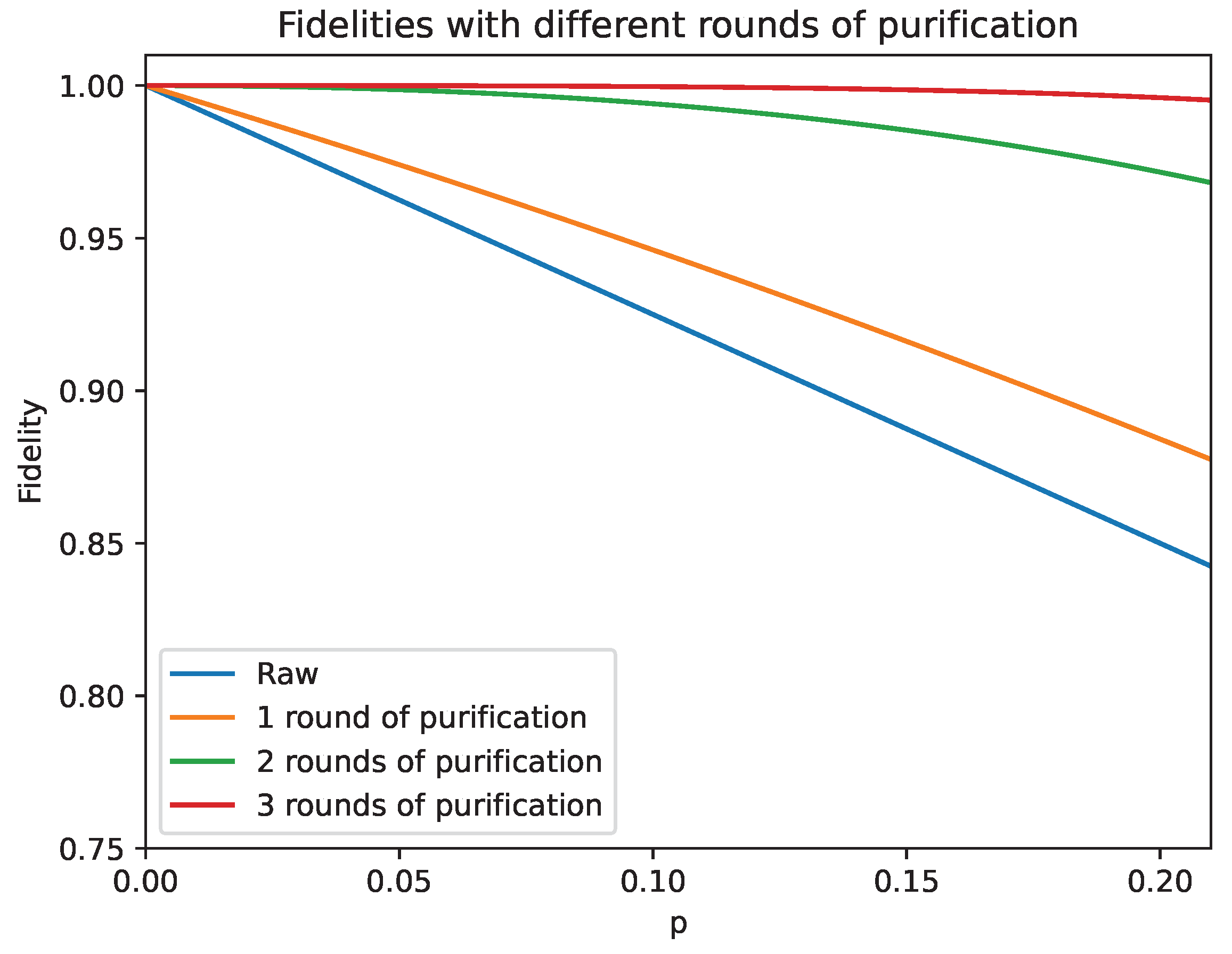
Furthermore, there is an intrinsic probabilistic nature associated to this method, as both measurements registered by the two parties must coincide in order to ensure a successful purification, as well as an asymptotic behaviour that limits the effectiveness of both high fidelity inputs and an increment on the number of rounds. As we see in Figure 9, the fidelity largely increases after a second distillation round, whereas with a third iteration the asymptotic behavior of the method enters into place and decreases the gain in the parameter. This only strengthens the argument in favour of the application of DEJMPS distillation in order to increase the fidelity to feasible limits for a successful communication, as the application of two rounds of distillation only consume two additional EPR pairs, whereas if we were to apply the method in Figure 7b each of the nodes would consume between 12–14 memory slots to land into the higher percentiles of the fidelity.
Circling back to Figure 9 we can extract an intuitive threshold for the tolerance of the fidelity around , as two rounds of purification take it close to , which, for small and medium messages is a tolerable value of the parameter. This threshold needs to be changed if we are dealing with larger quantity of data and should be moved towards . However, taking into account the asymptotic nature of the protocol a more complex fine tuning must be implemented in the communication scheme in order to transmit large packages of data.
8. Conclusions
In this paper, we have argued that simulation is an essential tool for understanding and designing quantum networks —especially, networks based on entanglement-distribution— not only as a complement to simplified analytical models, but mainly since entanglement is a physical resource inherently different to classical network entities, like conventional protocols or switching devices. Moreover, the efficient generation and distribution of entanglement prompts for a thorough rethinking of the internal architectures of quantum repeaters and switches. These architectural alternatives can be also addressed with a good simulation environment.
We have designed and programmed on top of NetSquid a generalized model for quantum switches and quantum repeaters, capable of handling an arbitrary number of memory units (qubits), taking fidelity as the primary decision variable for path selection, and with realistic depolarization noise in the channels and in the memory registers. Using this programming environment, fast prototyping and comparison between alternative network designs can be explored. As an example, we compared the advantages and performance of two typical configurations, a 2-hop network with multiple memory positions at the QR versus a standard repeater chain, and determined the achievable end-to-end fidelity in each case. This calculation is virtually intractable with a purely analytical approach. For future work, a more general simulator could be implemented, both from the engineering standpoint, by supporting more complex topologies and protocols, and from the physics standpoint, by adding more control over the experimental parameters that define the network, and exploring different technologies for quantum hardware.
Funding
TED2021-130369B-C31, TED2021-130369BC32, TED2021-130369B-C33 funded by MCIN/AEI/10.13039/501100011033 and by the “European Union NextGenerationEU/PRTR”. The work is also funded by the Plan Complementario de Comunicaciones Cuánticas, Spanish Ministry of Science and Innovation(MICINN), Plan de Recuperación NextGenerationEU de la Unión Europea (PRTR-C17.I1, CITIC Ref. 305.2022), and Regional Government of Galicia (Agencia Gallega de Innovación, GAIN, CITIC Ref. 306.2022).3). Additionally, This paper has been also funded by the Galician Regional Government under project ED431B 2024/41 (GPC).
References
- Azuma, K.; Bäuml, S.; Coopmans, T.; Elkouss, D.; Li, B. Tools for quantum network design. AVS Quantum Science 2021, 3, 014101. [Google Scholar] [CrossRef]
- Cacciapuoti, A.S.; Caleffi, M.; Tafuri, F.; Cataliotti, F.S.; Gherardini, S.; Bianchi, G. Quantum Internet: Networking Challenges in Distributed Quantum Computing. IEEE Network 2020, 34, 137–143. [Google Scholar] [CrossRef]
- Rohde, P.P. The Quantum Internet: The Second Quantum Revolution; Cambridge University Press, 2021. [CrossRef]
- Tamaki, K.; Lo, H.K.; Wang, W.; Lucamarini, M. Information theoretic security of quantum key distribution overcoming the repeaterless secret key capacity bound. 2018; arXiv:quant-ph/1805.05511]. [Google Scholar]
- Deutsch, D.; Ekert, A.; Jozsa, R.; Macchiavello, C.; Popescu, S.; Sanpera, A. Quantum Privacy Amplification and the Security of Quantum Cryptography over Noisy Channels. Phys. Rev. Lett. 1996, 77, 2818–2821. [Google Scholar] [CrossRef] [PubMed]
- Pirandola, S.; Laurenza, R.; Ottaviani, C.; Banchi, L. Fundamental limits of repeaterless quantum communications. Nature Communications 2017, 8. [Google Scholar] [CrossRef] [PubMed]
- Azuma, K.; Economou, S.E.; Elkouss, D.; Hilaire, P.; Jiang, L.; Lo, H.K.; Tzitrin, I. Quantum repeaters: From quantum networks to the quantum internet. Reviews of Modern Physics 2023, 95, 045006. [Google Scholar] [CrossRef]
- Li, J.; Wang, M.; Xue, K.; Li, R.; Yu, N.; Sun, Q.; Lu, J. Fidelity-Guaranteed Entanglement Routing in Quantum Networks. IEEE Transactions on Communications 2022, 70, 6748–6763. [Google Scholar] [CrossRef]
- Iñesta, A.G.; Wehner, S. Performance metrics for the continuous distribution of entanglement in multiuser quantum networks. Physical Review A 2023, 108, 052615. [Google Scholar] [CrossRef]
- Tillman, I.; Vasantam, T.; Towsley, D.; Seshadreesan, K.P. Calculating the Capacity Region of a Quantum Switch. 2024; arXiv:id=’quant-ph’/2404.18818]. [Google Scholar] [CrossRef]
- de Andrade, M.G.; Van Milligen, E.A.; Bacciottini, L.; Chandra, A.; Pouryousef, S.; Panigrahy, N.K.; Vardoyan, G.; Towsley, D. On the Analysis of Quantum Repeater Chains with Sequential Swaps 2024. arXiv:quant-ph/2405.18252]. [CrossRef]
- Zang, A.; Chung, J.; Kettimuthu, R.; Suchara, M.; Zhong, T. Analytical Performance Estimations for Quantum Repeater Network Scenarios 2024. arXiv:quant-ph/2407.11376]. [CrossRef]
- Coopmans, T.; Knegjens, R.; Dahlberg, A.; Maier, D.; Nijsten, L.; de Oliveira Filho, J.; Papendrecht, M.; Rabbie, J.; Rozpędek, F.; Skrzypczyk, M.; others. Netsquid, a network simulator for quantum information using discrete events. Communications Physics 2021, 4, 164. [Google Scholar] [CrossRef]
- Dahlberg, A.; Wehner, S. SimulaQron—a simulator for developing quantum internet software. Quantum Science and Technology 2018, 4, 015001. [Google Scholar] [CrossRef]
- Diadamo, S.; Nötzel, J.; Zanger, B.; Beşe, M.M. QuNetSim: A Software Framework for Quantum Networks. IEEE Transactions on Quantum Engineering 2021, 2, 1–12. [Google Scholar] [CrossRef]
- Wu, X.; Kolar, A.; Chung, J.; Jin, D.; Zhong, T.; Kettimuthu, R.; Suchara, M. SeQUeNCe: a customizable discrete-event simulator of quantum networks. Quantum Science and Technology 2021, 6, 045027. [Google Scholar] [CrossRef]
- Zang, A.; Chen, X.; Kolar, A.; Chung, J.; Suchara, M.; Zhong, T.; Kettimuthu, R. Entanglement Distribution in Quantum Repeater with Purification and Optimized Buffer Time. IEEE INFOCOM 2023 - IEEE Conference on Computer Communications Workshops (INFOCOM WKSHPS). IEEE, 2023. [CrossRef]
- Dür, W.; Briegel, H.J. Entanglement purification and quantum error correction. Reports on Progress in Physics 2007, 70, 1381–1424. [Google Scholar] [CrossRef]
- Dahlberg, A.; Skrzypczyk, M.; Coopmans, T.; Wubben, L.; Rozpundefineddek, F.; Pompili, M.; Stolk, A.; Pawełczak, P.; Knegjens, R.; de Oliveira Filho, J.; Hanson, R.; Wehner, S. A link layer protocol for quantum networks. Proceedings of the ACM Special Interest Group on Data Communication; Association for Computing Machinery: New York, NY, USA, 2019. [Google Scholar] [CrossRef]
- Kar, B.; Kumar, P. O: Protocols for Quantum Networks, 2023; arXiv:quant-ph/2305.00708]. [CrossRef]
- Nain, P.; Vardoyan, G.; Guha, S.; Towsley, D. On the Analysis of a Multipartite Entanglement Distribution Switch. Proceedings of the ACM on Measurement and Analysis of Computing Systems 2020, 4, 1–39. [Google Scholar] [CrossRef]
- Vardoyan, G.; Guha, S.; Nain, P.; Towsley, D. On the Capacity Region of Bipartite and Tripartite Entanglement Switching. ACM SIGMETRICS Performance Evaluation Review 2021, 48, 45–50. [Google Scholar] [CrossRef]
- Nain, P.; Vardoyan, G.; Guha, S.; Towsley, D. Analysis of a tripartite entanglement distribution switch. Queueing Systems 2022, 101, 291–328. [Google Scholar] [CrossRef]
- Panigrahy, N.K.; Vasantam, T.; Towsley, D.; Tassiulas, L. On the Capacity Region of a Quantum Switch with Entanglement Purification. 2022; arXiv:quant-ph/2212.01463]. [Google Scholar]
- Kamin, L.; Shchukin, E.; Schmidt, F.; van Loock, P. Exact rate analysis for quantum repeaters with imperfect memories and entanglement swapping as soon as possible. Physical Review Research 2023, 5, 023086. [Google Scholar] [CrossRef]
- Brand, S.; Coopmans, T.; Elkouss, D. Efficient Computation of the Waiting Time and Fidelity in Quantum Repeater Chains. IEEE Journal on Selected Areas in Communications 2020, 38, 619–639. [Google Scholar] [CrossRef]
- Shchukin, E.; Schmidt, F.; van Loock, P. Waiting time in quantum repeaters with probabilistic entanglement swapping. Physical Review A 2019, 100, 032322. [Google Scholar] [CrossRef]
- Zangi, S.M.; Shukla, C.; ur Rahman, A.; Zheng, B. Entanglement Swapping and Swapped Entanglement. Entropy 2023, 25, 415. [Google Scholar] [CrossRef]
- Vardoyan, G.; Guha, S.; Nain, P.; Towsley, D. On the exact analysis of an idealized quantum switch. Performance Evaluation 2020, 144, 102141. [Google Scholar] [CrossRef]
- Vardoyan, G.; Guha, S.; Nain, P.; Towsley, D. On the Stochastic Analysis of a Quantum Entanglement Distribution Switch. IEEE Transactions on Quantum Engineering 2021, 2, 1–16. [Google Scholar] [CrossRef]
- Zhao, Y.; Qiao, C. Redundant Entanglement Provisioning and Selection for Throughput Maximization in Quantum Networks. IEEE INFOCOM 2021 - IEEE Conference on Computer Communications, 2021, pp. 1–10. [CrossRef]
- Vasantam, T.; Towsley, D. Stability Analysis of a Quantum Network with Max-Weight Scheduling 2021. arXiv:quant-ph/2106.00831]. [CrossRef]
- Vardoyan, G.; Skrzypczyk, M.; Wehner, S. On the quantum performance evaluation of two distributed quantum architectures. Performance Evaluation 2022, 153, 102242. [Google Scholar] [CrossRef]
- Vasantam, T.; Towsley, D. A throughput optimal scheduling policy for a quantum switch. Quantum Computing, Communication, and Simulation II; Hemmer, P.R.; Migdall, A.L., Eds. SPIE, 2022. [CrossRef]
- Vardoyan, G.; Wehner, S. Quantum Network Utility Maximization. 2023 IEEE International Conference on Quantum Computing and Engineering (QCE). IEEE, 2023. [CrossRef]
- Kozlowski, W.; Dahlberg, A.; Wehner, S. Designing a quantum network protocol. Proceedings of the 16th international conference on emerging networking experiments and technologies, 2020, pp. 1–16.
- Goodenough, K.; Coopmans, T.; Towsley, D. On noise in swap ASAP repeater chains: exact analytics, distributions and tight approximations 2024. arXiv:quant-ph/2404.07146]. [CrossRef]
- Hübel, H.; Vanner, M.R.; Lederer, T.; Blauensteiner, B.; Lorünser, T.; Poppe, A.; Zeilinger, A. High-fidelity transmission of polarization encoded qubits from an entangled source over 100 km of fiber. Optics Express 2007, 15, 7853–7862. [Google Scholar] [CrossRef] [PubMed]
- Herbauts, I.; Blauensteiner, B.; Poppe, A.; Jennewein, T.; Huebel, H. Demonstration of active routing of entanglement in a multi-user network. Optics express 2013, 21, 29013–29024. [Google Scholar] [CrossRef]
Figure 1.
Intuition behind the quantum switch. Several nodes are displayed around it and three of them request a connection amongst them.
Figure 1.
Intuition behind the quantum switch. Several nodes are displayed around it and three of them request a connection amongst them.
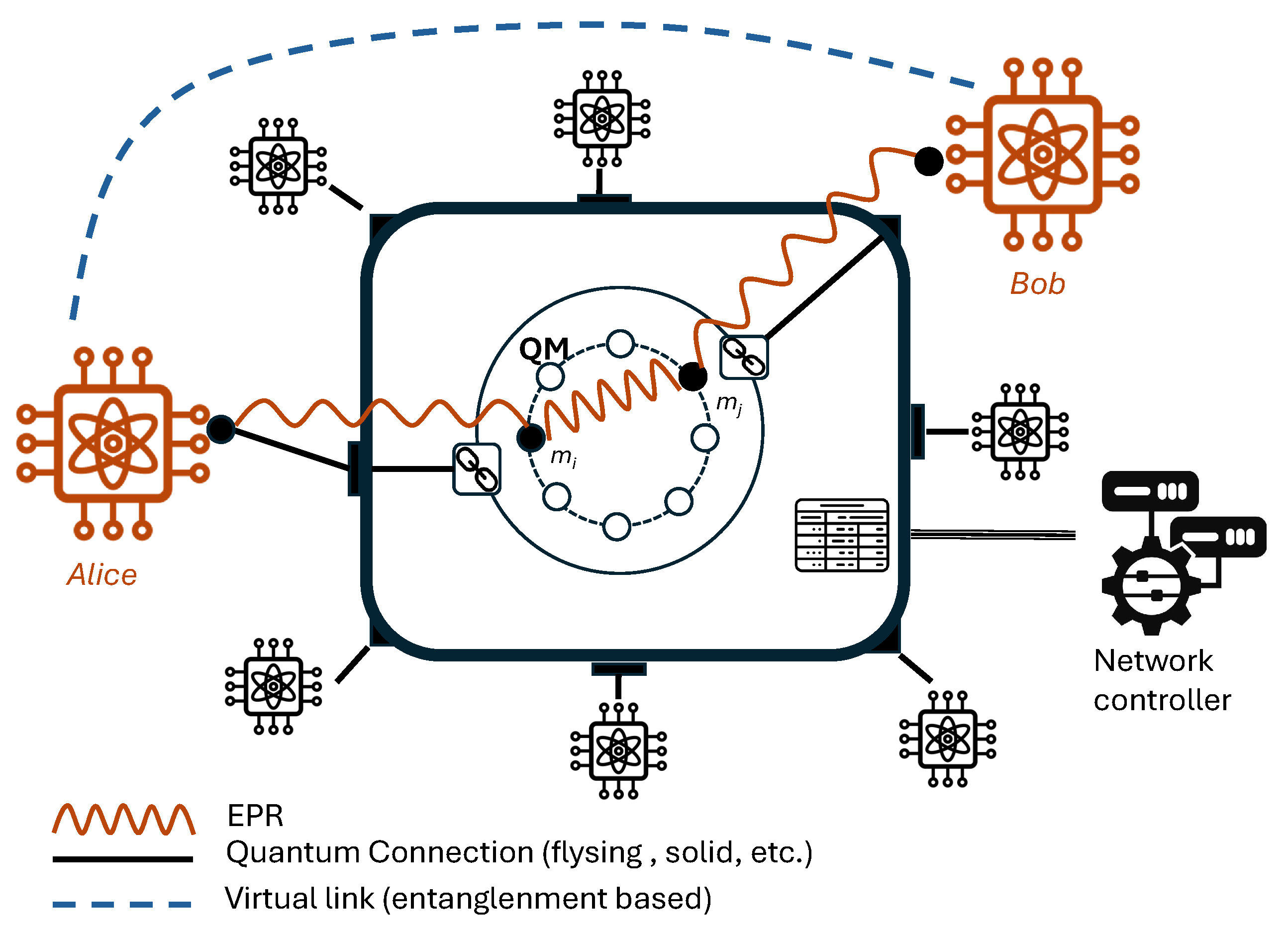
Figure 2.
Overview of software architecture in NetSquid (extracted from [13]).
Figure 2.
Overview of software architecture in NetSquid (extracted from [13]).
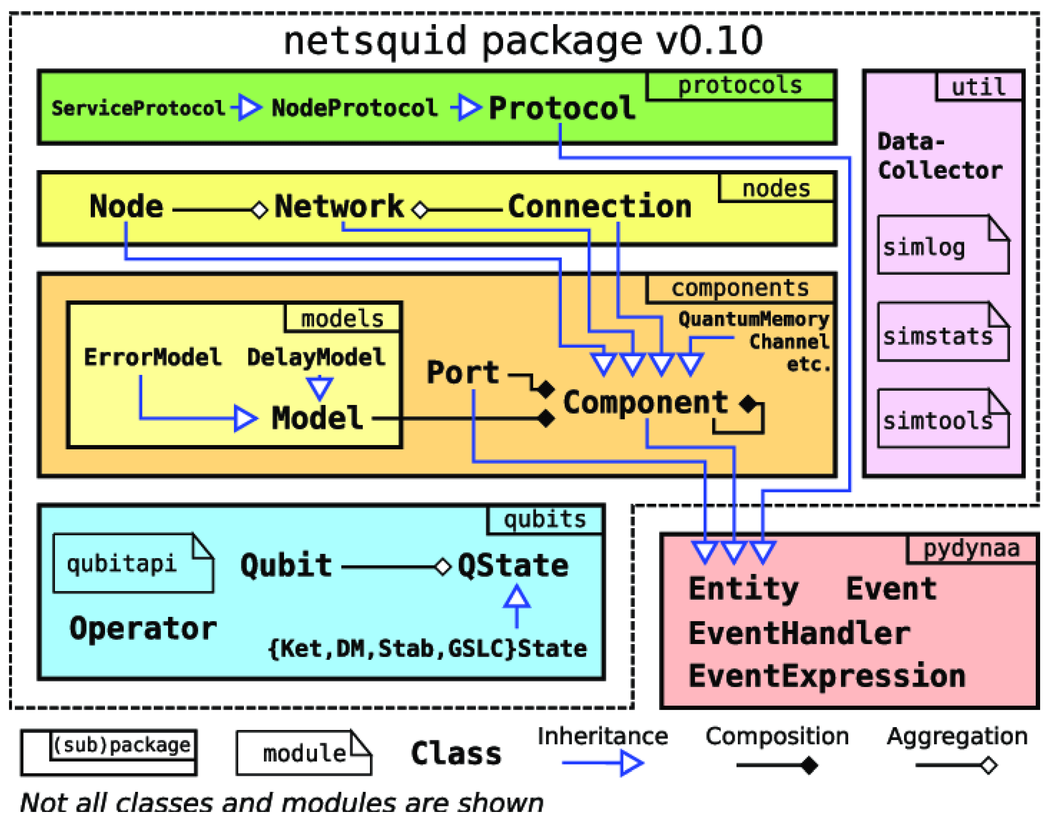
Figure 3.
Scheme for the quantum communication scenario, including the main quantum mechanism, swapping and correct protocols and purification.
Figure 3.
Scheme for the quantum communication scenario, including the main quantum mechanism, swapping and correct protocols and purification.
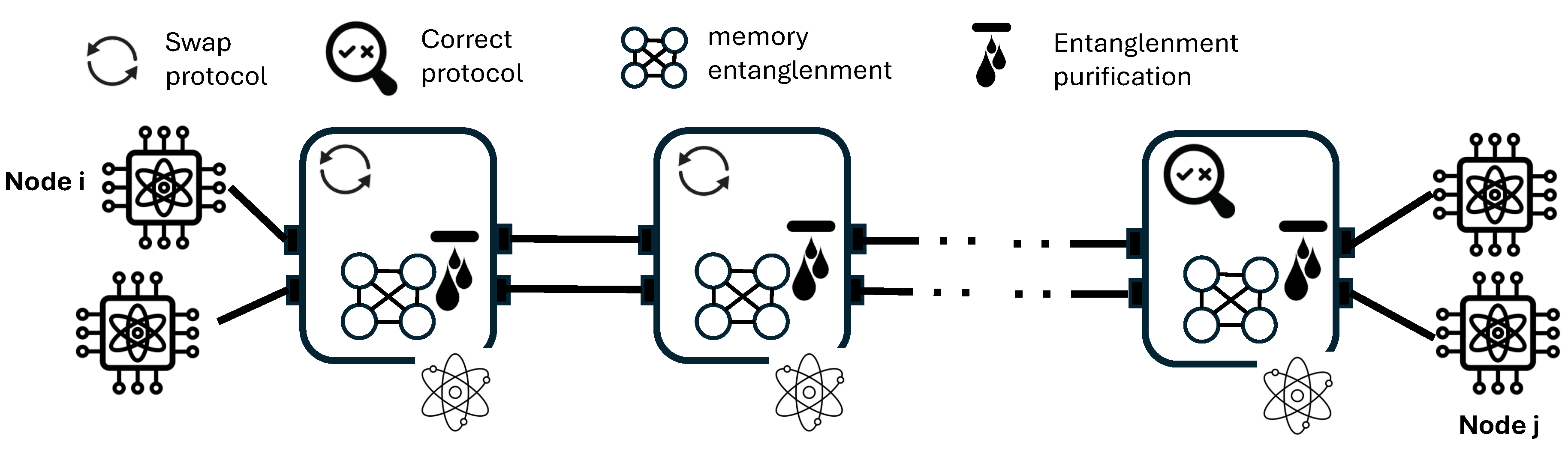
Figure 4.
Implementation architecture of the relay network in NetSquid.
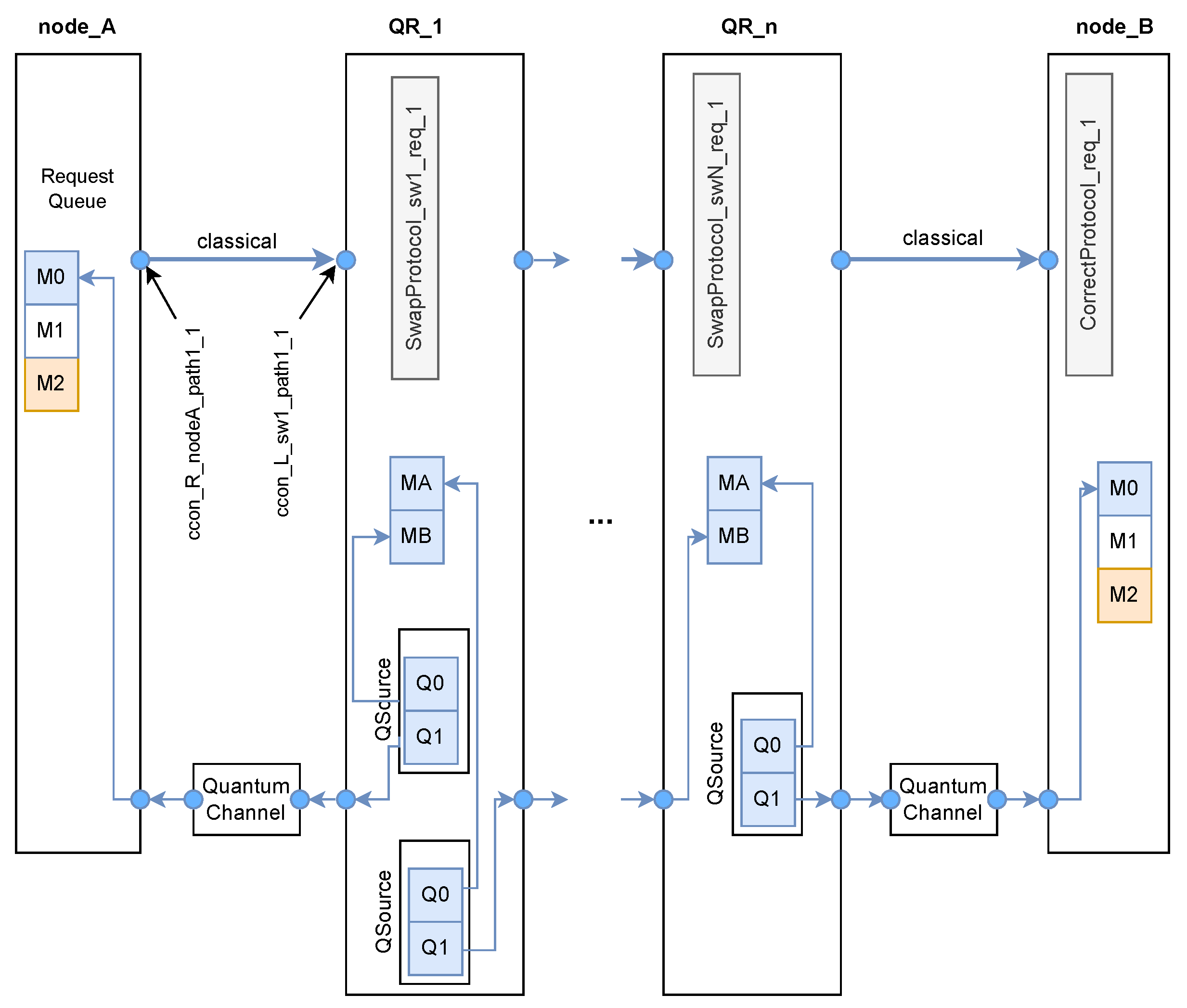
Figure 5.
Architecture discussed in Section 6.2. A two-hop network is established and the program arranges and identifies the fidelity of the entangled pairs for each of the connections and the route with the highest fidelity is selected to drive the communication.
Figure 5.
Architecture discussed in Section 6.2. A two-hop network is established and the program arranges and identifies the fidelity of the entangled pairs for each of the connections and the route with the highest fidelity is selected to drive the communication.
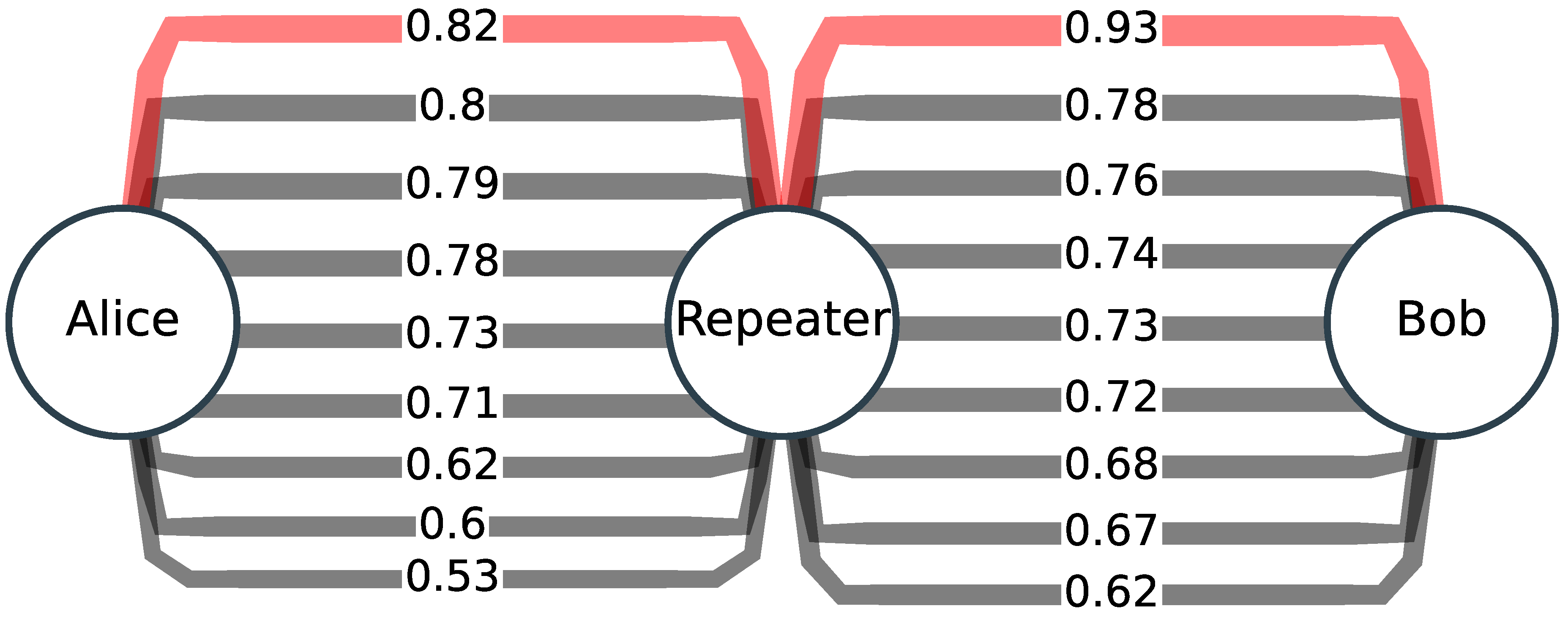
Figure 6.
(Color online) Fidelity average for the two different protocols discussed, PS and SP. These simulations have been performed in a network of 3 nodes. Error bars correspond to 1 standard deviation.
Figure 6.
(Color online) Fidelity average for the two different protocols discussed, PS and SP. These simulations have been performed in a network of 3 nodes. Error bars correspond to 1 standard deviation.
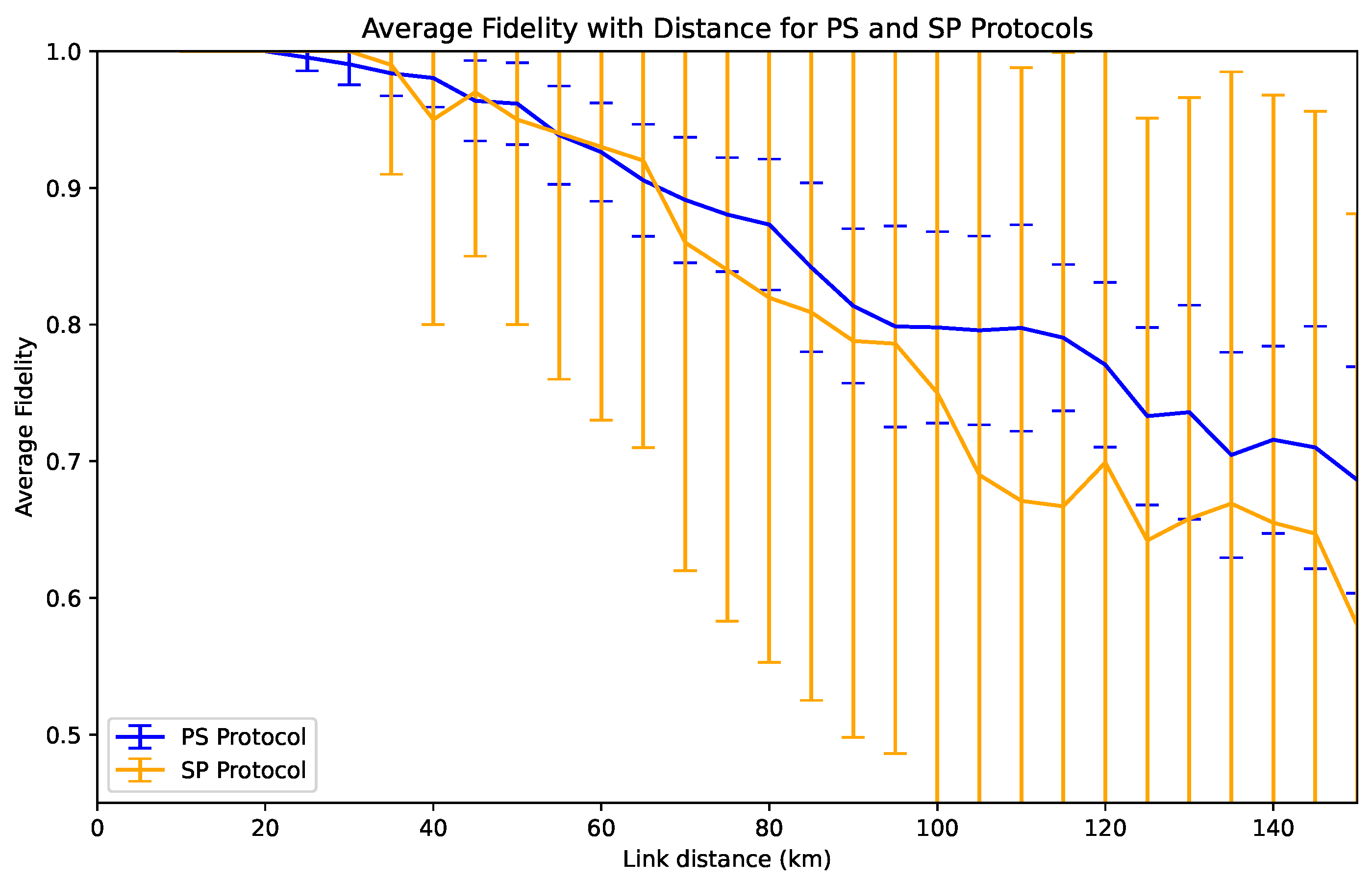
Figure 7.
Comparison of the impact on fidelity by varying the number of intermediate QR (Figure 7a) and by varying the number of memory positions in a QR (Figure 7b). Error bars represent the standard deviation of multiple simulations.
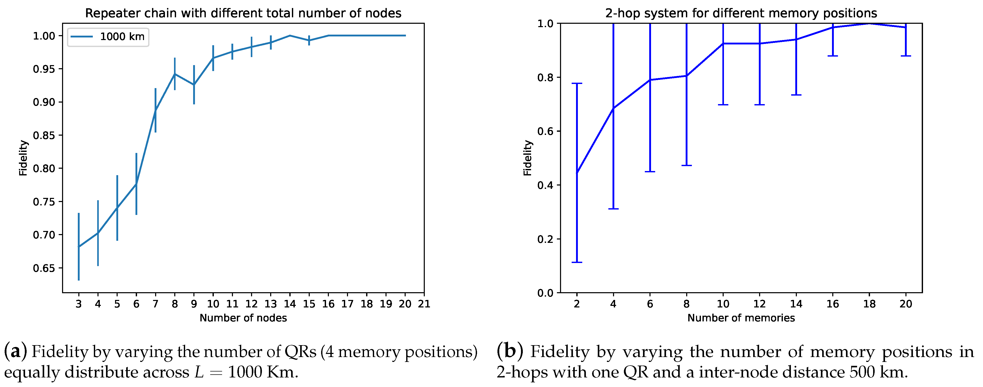
Figure 8.
Simulation for a three node network applying one round of DEJMPS distillation protocol.
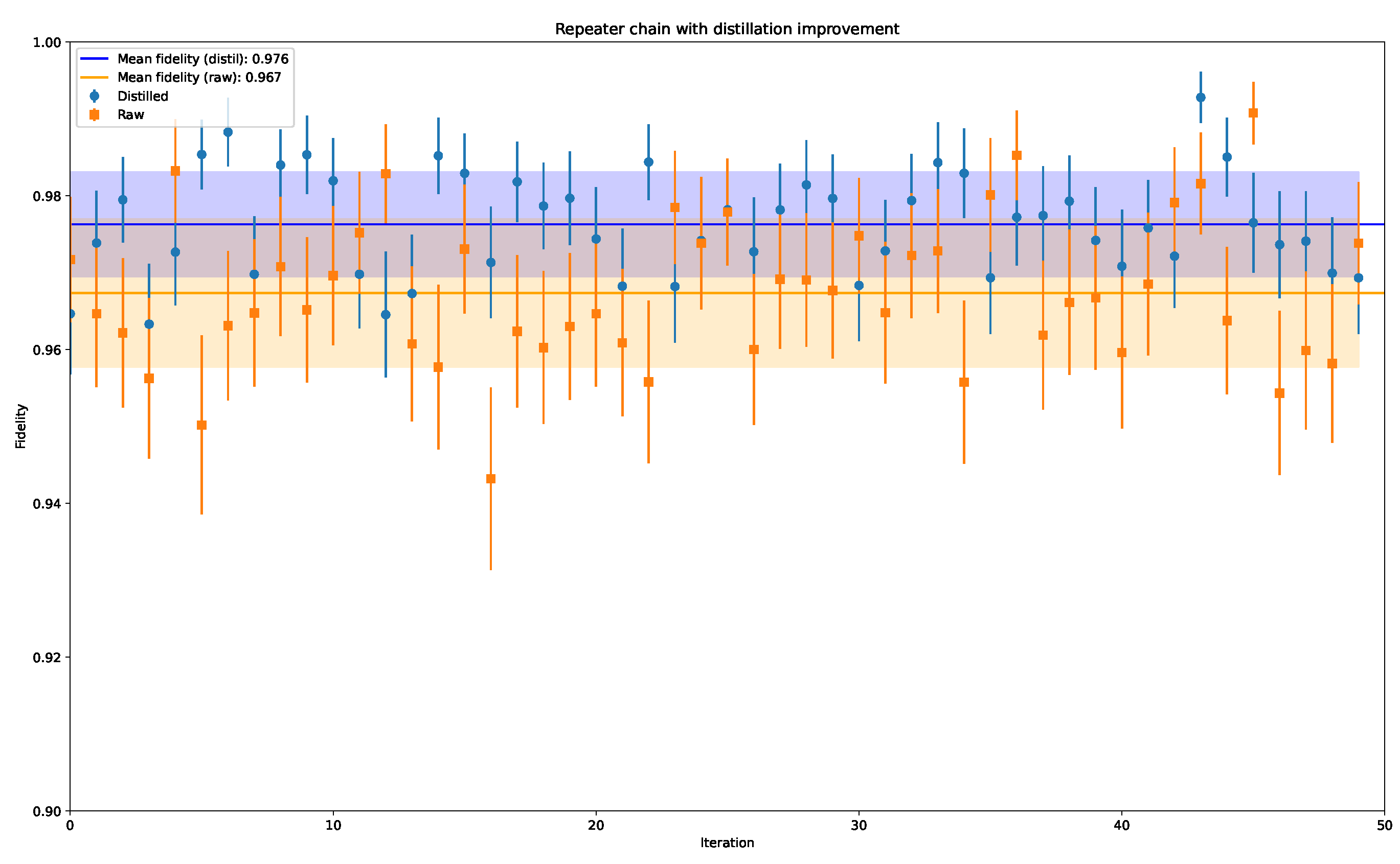
Figure 9.
Representation of the theoretical increment in the fidelity after applying several rounds of purification. The total depolarizing probability of the channel is represented in the axis vs. the fidelity output of the process.
Figure 9.
Representation of the theoretical increment in the fidelity after applying several rounds of purification. The total depolarizing probability of the channel is represented in the axis vs. the fidelity output of the process.
Disclaimer/Publisher’s Note: The statements, opinions and data contained in all publications are solely those of the individual author(s) and contributor(s) and not of MDPI and/or the editor(s). MDPI and/or the editor(s) disclaim responsibility for any injury to people or property resulting from any ideas, methods, instructions or products referred to in the content. |
© 2024 by the authors. Licensee MDPI, Basel, Switzerland. This article is an open access article distributed under the terms and conditions of the Creative Commons Attribution (CC BY) license (https://creativecommons.org/licenses/by/4.0/).
Copyright: This open access article is published under a Creative Commons CC BY 4.0 license, which permit the free download, distribution, and reuse, provided that the author and preprint are cited in any reuse.


