Submitted:
02 October 2024
Posted:
02 October 2024
You are already at the latest version
Abstract
This article presents a conceptual program model that integrates three main methods: object recognition, color classification, and QR decoding of information. These methods are well-established in the fields of Robotics and Artificial Intelligence, yet they remain subjects of ongoing research interest. The program model organizes the execution of the methods in a sequence directed toward recognized objects. In this way, color classification and QR decoding are performed only on already recognized objects. Colors and QR codes that do not belong to recognized objects are not analyzed, which can provide intelligent robots with reliable and accurate information about the objects they can recognize. For research purposes, image sensors (cameras), images saved to disk, clipboard, or shared memory between applications are used. The article shows that the program model can be augmented with various sensors and algorithms for the comprehensive construction of program control of autonomous robots. Future research that builds on current studies will focus on measuring the distance to recognized objects and structuring the collected information about these objects, which will create opportunities for perceptual anchoring and logical reasoning in the program control of intelligent robots.
Keywords:
object recognition
; color classification
; QR decoding
; mobile robots
; dynamic environment
; perceptual anchoring
; artificial intelligence
1. Introduction
Intelligent robots (IRs) are agents physically integrated into specific external environments. They employ sensors to monitor their surroundings and utilize executive mechanisms to enact actions within them. The behavior of an IR cannot be comprehensively considered or evaluated without accounting for the environment it operates in and the tasks it performs. The robot, its environment, and the task at hand are interdependent and mutually influential. The interest behind research and development in IR is driven by the necessity and aspiration for robots to function effectively in everyday human environments such as offices, hospitals, museums, galleries, and warehouses. Mobile intelligent robots [1] must adapt their behavior in dynamic and changing conditions, which requires these robots to possess qualities different from those of industrial robots. This article presents a program model that integrates capabilities for object recognition, color classification of recognized objects, and QR code decoding. These three algorithms are combined into a unified program model with a specific execution sequence. The model can provide the intelligent robot with rich and accurate information about its surrounding environment.
The article presents the possibility of enhancing the program model with various sensors and algorithms, making it flexible and capable of adapting to different robotic systems. The model can be included as part of the overall intelligent software management of a robot, which will enable the robot to make informed decisions based on the collected data.
For research and experimentation purposes, the program includes a menu that allows the use of multiple image sources: cameras, images saved on disk, clipboard, or shared memory between applications. Several experimental results are presented to demonstrate the functionality of the program model.
The use of sensors (RGB-D cameras [2]) for measuring distance to recognized objects and the storage of structured information generated by the execution of the program model will be the subject of future research that builds upon the current studies. Structuring information appropriately within the computer system and generating instances that carry this information creates opportunities for implementing perceptual anchoring [3], i.e., establishing a connection between perceptions and signs. This connection can be utilized for the purposes of logical reasoning and decision-making by the IR.
2. Program Model
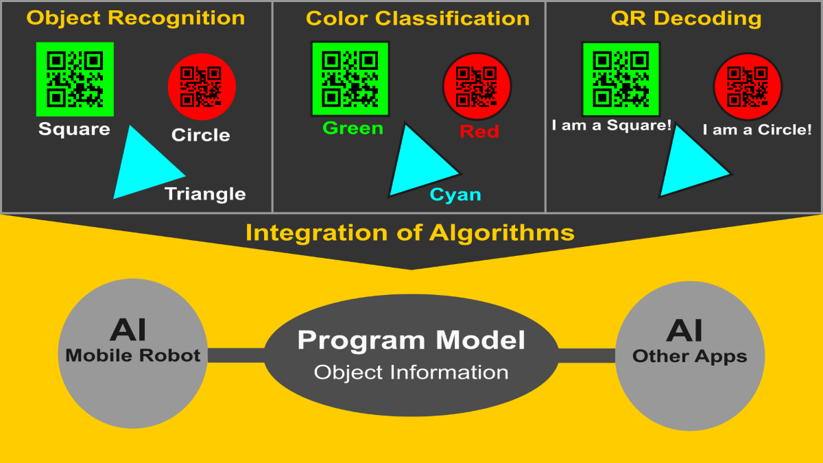
The program model is implemented as a console C++ application that integrates several analysis algorithms applied sequentially to the input images. The program serves as a conceptual model with an architecture that encompasses the following three main functionalities (Figure 1):
- Object recognition: identification and localization of various types of objects within the input images.
- Color classification of objects: color analysis of the recognized objects to determine their color within one of six possible color categories.
- QR decoding: extracting information from QR codes located within the recognized objects.
This software architecture provides an integrated solution for tasks related to computer vision, which is essential for the development of intelligent robots. The program is built using system libraries for shared memory [4] and the OpenCV library [5], which provides a comprehensive solution for image processing and visualization.
Figure 2 shows a block diagram that presents the overall organization of the program model and its structured approach. There are three main components: Initialization, Selection Menu, and Image Processing.
The program model contains the following main components:
- Initialization: Creation of variables and windows for displaying images, a trackbar window for setting RGB thresholds (filtering) applied to the input image, and camera initialization.
- Selection menu: The program provides a menu from which users can select from a list of alternative sources for loading images or can exit the program.
- Cyclic image processing: The loop provides continuous updates of the images, which are processed using various methods from OpenCV-setting a color threshold, finding contours, approximating the detected contours, and determining the objects detected in the image. A specialized function is called to perform color classification of the recognized objects. Each recognized object is labeled with an appropriate name and number. After recognition and color classification, the program provides the opportunity to decode QR codes that are located within the recognized objects. The program executes this cycle until the user presses the "e/E" key.
- End of program: The program completes its execution if the user selects to exit the program by pressing the "e/E" key.
In summary, the functionality of the program model consists of the following:
- Capturing a frame (image) from a source selected from the menu;
- Extracting information from the frame and recognizing objects;
- Color classification of the recognized objects;
- Assigning identifiers to the recognized objects;
- Decoding QR codes within the objects, if any;
- Displaying results in windows.
3. Object Recognition
3.1. Presentation of the Algorithm
The goal of object recognition is to identify and localize all instances of objects from one or more known classes in images [6]. These classes are defined according to the application’s objectives. Typically, there are a small number of objects in the image, but their location and scale may vary.
The object recognition algorithm implemented in the program model allows for the recognition of several object classes in real-time. At this stage, the program does not store information about the objects, meaning that the algorithm only determines the class of a given object and its characteristics. For experimental purposes, simple 2D shapes (classes) have been chosen, which can have various applications in robotics. The classes that can be recognized by the algorithm include: circles, triangles, rectangles, pentagons, and hexagons. The recognition is robust to rotation and scale changes of the objects.
When executing the program, it goes through the following steps:
Step 1: Choosing a source for images - usb camera, disk or other.
cout << "******************************" << "\n";
cout << "SELECT AN OPTION FROM THE MENU" << "\n";
cout << "******************************" << "\n";
cout << "1. Load from camera" << "\n";
cout << "2. Load from Shared Memory" << "\n";
cout << "3. Load from Picture" << "\n";
cout << "4. Load from Clipboard" << "\n";
cout << "5. Exit" << "\n";
cout << "Your choice: ";
cin >> choice;
Step 2: The Update function is called in the main program loop. The inRange function creates a binary image where the pixels that fall within the specified color range are white, while the rest are black. It takes the current frame, applies the specified color boundaries to it, and stores the resulting image in thresholded
void Update() {
inRange(frame, Scalar(lowB, lowG, lowR), Scalar(highB, highG, highR), thresholded);
//...
}
The inRange function performs color-based segmentation using the lower and upper color boundaries, which are set interactively via a trackbar (Figure 3).
The inRange function can work with both RGB (Red, Green, Blue) and HSV (Hue, Saturation, Value) images [7]. HSV is more effective for color segmentation and is closer to how humans perceive colors, as the model mimics the human ability to distinguish colors [8]. The HSV color model is less sensitive to changes in lighting, making it suitable for color segmentation. In the current implementation, inRange uses the RGB model because it is intuitive and convenient for visualizing the results, facilitating color interpretation in the context of technical goals and experiments.
Step 3: Contours of objects with well-defined boundaries in the image are detected. The contour of an object plays a crucial role in areas such as semantic segmentation and image classification. Extracting contours is a difficult task, especially when the contour is incomplete or open [9].
The OpenCV library provides the function findContours, which detects contours in the created binary image (thresholded).
void Update() {
// Segments the image based on a specified color range
inRange(frame, Scalar(lowB, lowG, lowR), Scalar(highB, highG, highR), thresholded);
vector<vector<Point>> contours; //Vector to store contours
// Finds the contours in the binarized image
findContours(thresholded, contours, RETR_EXTERNAL, CHAIN_APPROX_SIMPLE);
//...
}
Step 4: All found contours are traversed, and each contour is simplified using the approxPolyDP function. This function reduces the number of points on the contour to describe the shape with a minimal number of vertices while preserving the essential geometry. Based on the number of vertices of the contours, the class of the object is determined (for example, triangle, rectangle, pentagon, etc.). For each recognized object, the colorClassification function is called to determine the color of the object.
void Update() {
// Segments the image based on a specified color range
inRange(frame, Scalar(lowB, lowG, lowR), Scalar(highB, highG, highR), thresholded);
vector<vector<Point>> contours; //Vector to store contours
// Finds the contours in the binarized image
findContours(thresholded, contours, RETR_EXTERNAL, CHAIN_APPROX_SIMPLE);
//loop the contours
for (const auto& contour : contours) {
double epsilon = 0.02 * arcLength(contour, true);
vector<Point> approx;
approxPolyDP(contour, approx, epsilon, true); //approximation of contour
// Skip small or non-convex objects
if (fabs(contourArea(contour)) < 100 || !isContourConvex(approx))
continue;
if (approx.size() == 3) {
// triangle
colorClassification(/*Operating parameters are passed here/*) ; }
else if (approx.size() == 4) {
// rectangle
colorClassification(/*Operating parameters are passed here/*) ; }
else if (approx.size() == 5) {
// pentagon
colorClassification(/*Operating parameters are passed here/*) ; }
else if (approx.size() == 6) {
// hexagon
colorClassification(/*Operating parameters are passed here/*) ; }
else
{
// Detect and label circles
colorClassification(/*Operating parameters are passed here/*) ; }
}
//...}
3.2. Specifics of the Algorithm
The object recognition algorithm is integrated into the program model as a fundamental component in the execution of the program. In order for the subsequent stages of information processing, color classification and QR decoding, to be successfully executed, the objects must be recognized.
It should be noted that the result of the algorithm depends on the following:
- The quality of the images: Images from the sensors often have noise, which is generated for various reasons, such as a low-quality sensor, poor WiFi signal, inadequate lighting, etc. This noise leads to difficulties in processing images in real time. The problem can largely be solved by using high-quality sensors (cameras), high resolution and frame rates, appropriate lenses, focal lengths, and good lighting. To improve the quality of images at the pixel level, various filters can be applied, such as the Gaussian filter [10], deep local parametric filters using neural networks [11], and others.
- Visibility of objects. The visibility and size of the objects captured in the images depend on many factors: technical equipment, the distance of the objects from the camera, shading, light reflections, etc. This means that the lighting and camera must be positioned appropriately in order for the objects in the image to be qualitatively analyzed [12,13]. In the case of static robots, lighting and cameras can be selected and placed at suitable positions and distances relative to the working objects in the environment. For mobile robots, the situation is more complex, as the choice of lighting and cameras depends on many factors in the robot-environment relationship - the tasks the robot performs, the dynamics of the environment, and more. In partially observable environments, where certain properties of the surroundings can only be perceived under specific conditions and from particular viewpoints, various approaches can be applied to adapt sensor information in the context of dynamic and changing conditions [14]. In complex or incomplete image contexts, attribute recognition techniques that belong to objects can be particularly effective in object recognition under insufficient information [15].
- Determining Color Threshold Values. The color threshold values are used to filter the input image, helping to separate the target object from unnecessary information in the image. Determining these threshold values through a trackbar or another manual method complicates the algorithm and makes it unreliable in response to changes in lighting, shading from objects, reflections, background changes, and other external influences.
- To minimize these issues, various approaches can be used. For example, when possible, a color background that is easy to remove can be utilized. Problems related to changes in lighting can be addressed by ensuring good illumination and using an additional sensor that measures the light level. Based on the sensor data, appropriate color threshold values can be pre-defined and automatically applied. These solutions are not always applicable, so algorithms that automatically adapt the color thresholds can be employed. For instance, by locally calculating regions using an iterative process, threshold values can be automatically computed without the need for pre-defined thresholds or parameters [16]. Another method for multi-level segmentation, based on the Emperor Penguin Optimizer (EPO) algorithm, offers an approach for automatically determining threshold values using optimization algorithms for efficient and precise image segmentation [17].
4. Classification of Objects by Colors
4.1. A Color Classification Model
The color classification model is built in Matlab and is based on a generalized mathematical model for linear decision filters (linear classification) [18]. Based on this model, an algorithm has been developed in C++ that classifies recognized objects in real-time into one of the following 6 colors: Red, Green, Blue, Magenta, Cyan, Yellow.
Building the model in Matlab follows these steps:
- Construction of a 3D color model in RGB space;
- Transformation of the 3D model into a 2D color model;
- Construction of lines for color separation in the 2D space;
- Testing of the model. 4.1.1.
4.1.1. Building a 3D Color Model in the RGB Space
To build the 3D model, the RGB space [19] along the three axes is divided into equal intervals within the range of [0, 1]. The number of intervals is chosen so that the program executes in an acceptable time. Increasing the number of intervals leads to delays in the execution of the program and does not significantly contribute to the performance of the model. For this reason, an optimal number of points along the three axes is selected to be 51, creating 50 intervals for each axis of the RGB space. Each interval has a size of 0.02 units. The first point has coordinates (0, 0, 0), and the last (1, 1, 1). The total number of points in the three-dimensional space for the RGB colors is calculated as: 51 x 51 x 51 = 132651 points. The creation of these points in Matlab is performed using a triple loop.
for r = points(0, 1, 51) %Red points, 50 intervals across 0.02 units in the interval [0, 1]
for g = points(0, 1, 51) %Green points, 50 intervals
for b = points(0, 1, 51) %Blue points, 50 intervals
index = index + 1;
RGB_3D_Color_Matrix(index, :) = [r g b]; %Adds the new [r g b] values
This loop creates a three-dimensional color space RGB_3D_Color_Matrix with all possible combinations of RGB colors for the selected number of points (Figure 4).
4.1.2. Convert the RGB 3D Color Space to 2D (rgb)
The next step in building the color classification model is to convert the three-dimensional RGB space into a two-dimensional space. For this purpose, the color values along the three coordinates are normalized using the following formulas [18]:
r = R/(R + G + B), g = G/(R + G + B), b = B/(R + G + B).
In the representation of the two-dimensional space, the coordinates r and g are important, as the b coordinate can be calculated using the formula b = 1 – (r + g). That is, the sum of the three coordinates in the two-dimensional space is equal to one: r + g + b = 1.
To convert from the three-dimensional space to the two-dimensional space, a loop has been created that iterates through the RGB_3D_Color_Matrix, and each RGB point (pixel) is passed to the function RGB_3D_To_rgb_2D.
for k = 1:index;
R = RGB_3D_Color_Matrix(k,1);
G = RGB_3D_Color_Matrix(k,2);
B = RGB_3D_Color_Matrix(k,3);
%Each point is converted to a two-dimensional coordinate.
[r g, b] = RGB_3D_To_rgb_2D(R,G,B);
The conversion function has the following form:
function [r, g, b] = RGB_3D_To_rgb_2D(R, G, B)
RGB = R + G + B;
if (RGB == 0) r = 0; g = 0; b = 1;
else r = R / RGB; g = G / RGB; b = B / RGB;
If the input values of R, G, B are zero, the function RGB_3D_To_rgb_2D returns r = 0, g = 0, b = 1.
The output of the graph of the two-dimensional RGB space is shown in Figure 5. Only the rg coordinates are used for this graph, while b can be calculated.
To generate the displayed graph, the values of the colors r and g in the two-dimensional space, which range from [0, 1], are converted into integers within the range of [0, 100]. This is done because, in addition to being color values, r and g are also used for indexing an array associated with the r and g coordinates, facilitating convenient and fast data processing. The white area at the center of the triangle is achieved with values close to r ≈ 0.33, g ≈ 0.33, and b ≈ 0.33. The black triangular area at the bottom of the graph is not utilized.
The transformation of the interval [0, 1] to the interval [1, 100] for the two coordinates rg is done using the formulas x_green = 1 + g * 99 and y_red = 1 + r * 99, where g is the value of the green color and r is the value of the red color in the two-dimensional space. The addition of one is for correct indexing of the array, which starts from 1 instead of 0. The first 6 indices obtained from the formulas are shown in Figure 6.
The black pixels visible in the color two-dimensional space are a result of indexing the array representing the graph using the actual values of r and g in the interval [0, 1], and the results for x_green and y_red are rounded to whole numbers in the interval [1, 100]. This does not affect the classification algorithm, as the output of the graph in Figure 5 is for demonstration purposes, and the pixel values, including the black ones, are not used directly. A more generalized model is employed by drawing lines in the two-dimensional space, so that if the color falls into a pixel marked in black on the graph, it will be recognized in the correct color.
4.1.3. Construction of Lines for Color Separation in the 2D Space
From Figure 5, it can be seen that several primary colors stand out in the two-dimensional space: Red, Green, and Blue. There are also three additional colors that are well represented in the graph: Magenta, Cyan, and Yellow. Since these colors are distinctly visible, the classification model is built for these 6 colors. To achieve color classification of the objects, lines have been drawn to separate these color spaces, as shown in Figure 7.
As seen from the figure, the values y_red=40 and y_red=60 separate the Magenta color, with the lines drawn through these points passing through the center of the triangle, where the color appears white. Similarly, the lines for the other colors are determined. The number of lines drawn depends on the desired number of colors for classification, with 6 colors (Red, Green, Blue, Magenta, Cyan, Yellow) defined here.
The lines on the graph are limited to the shown short segments for clarity. In reality, these lines extend in both directions towards infinity. The determination of the equations of the lines is based on the mathematical equation of a line intersecting the coordinates x and y. The general equation of a line is: y = m.x + b, where m is the slope, and the y-intercept is b. The slope is calculated using the following formula:
m = (change in y) / (change in x).
The determined coefficients for the six lines of the model have the following values:
Dbr1 = [-6 -34 1360] % first green line
Dbr2 = [-26 -34 2040] % second green line
Dbg1 = [34 6 -1360] % first red line
Dbg2 = [34 26 -2040] % second red line
Drg1 = [-26 6 680] % first blue line
Drg2 = [-6 26 -680] % second blue line
The signs (+) and (-) next to the line equations indicate the sign of Dbr1, Dbr2, Dbg1, Dbg2, Drg1, and Drg2. If a specific combination of r and g yields a negative result, the color falls into the area marked with a minus sign (-); if the result is positive, the color is on the side marked with a plus sign (+).
The procedure for color classification of a recognized object is as follows:
- The average color value for the recognized object in the three-dimensional RGB space is determined, with values in the range [0, 255].
- The resulting RGB color is converted to the rgb two-dimensional space in the range [0, 1]. The rg values are used to determine the following two values:x_green = 1 + g * 99; y_red = 1 + r * 99,
- where x_green and y_red are the color values of the recognized object in the two-dimensional space for the classification model.
- The obtained values of x_green and y_red are substituted into the equations of Zbr1, Zbr2, Zbg1, Zbg2, Zrg1, Zrg2, shown below, and only the resulting sign is considered.
The Matlab code that classifies the color of the object is as follows:
W = [x_green; y_red; 1];
Zbr1=Dbr1*W;
Zbr2=Dbr2*W;
Zbr1 = -6*x_green - 34*y_red + 1360;
Zbr2 = -26*x_green - 34*y_red + 2040
Zbg1=Dbg1*W;
Zbg2=Dbg2*W;
Zbg1 = 34*x_green + 6*y_red - 1360;
Zbg2 = 34*x_green + 26*y_red - 2040
Zrg1=Drg1*W;
Zrg2=Drg2*W;
Zrg1 = -26*x_green + 6*y_red + 680;
Zrg2 = -6*x_green + 26*y_red - 680
IF (Zbr1>0 && Zbg1<0) disp('blue');
IF (Zbg1>=0 && Zbg2<=0) disp('cyan');
IF (Zbg2>0 && Zrg2<0) disp('green');
IF (Zrg2>=0 && Zrg1<=0) disp('yellow');
IF (Zrg1>0 && Zbr2<0) disp('red');
IF (Zbr2>=0 && Zbr1<=0) disp('magenta');
In the program model (the C++ implementation), the function colorClassification() is used for color classification of the recognized object.
void colorClassification(/*Operating parameters are passed here/*) {
//The Matlab program code for color classification is implemented here
//...
if(qr_choice == 'Y' or qr_choice == 'y') QRDetector(subImg); //Call QRDetector
//...}
4.2. Testing the Classification Model
Average RGB color values for an object are set in the Matlab program.
Example 1:
An object with red color is defined in the program: R = 255, G = 0, B = 0.
Running the program >> color_classification_objects
Returned result (Figure 8): red
The green star indicates where in the 2D model space the object's color is located.
Example 2:
An object with yellow color is defined in the program: R = 255, G = 255, B = 0.
Running the program >> color_classification_objects
Returned result (Figure 9): yellow
The gray star indicates where in the 2D model space the object's color is located.
Correct results are obtained with other RGB values as well, which indicates that the color classification model is properly constructed.
5. QR decode
5.1. Description
QR code (quick-response code) is a two-dimensional matrix barcode [20] that stores information in the form of text, numbers, web addresses, and more. The information from the QR code becomes accessible upon decoding.
QR codes are successfully used for object identification, as well as landmarks in space, where they can be key elements in the processes of localization ("where the robot is") and navigation ("how the robot gets to the goal") [21,22,23,24]. QR coding with fiducial markers, such as AprilTag, allows for camera calibration, object and camera localization (position and orientation), and even environment mapping [25,26,27].
QR decoding is a built-in functionality in the presented program model (AprilTag is not used at this stage), which includes:
Activation of QR decoding: In the program, the user can choose whether to enable the functionality for decoding QR codes.
cout << "QR code recognition (Y, N): ";
cin >> qr_choice;
...
if(qr_choice == 'Y' or qr_choice == 'y')
QRDetector(subImg);
- Detection of the QR code: The program uses the QRDetector function to identify the area of the QR code. In the current implementation of the program, the QR code must be located within the recognized object detected by the program.
- Decoding the information: The code recognition algorithm decodes the information using the detectAndDecode method. This information can include plain text, numbers, URLs, or other data.
5.2. Implementation
The analysis of an image containing a QR code is performed using functions declared in the objdetect.hpp header of the OpenCV library [5]. The functions for working with QR codes in OpenCV are provided through the QRCodeDetector class, which offers methods for decoding QR codes.
In the presented program model, QR decoding is carried out in the function:
void QRDetector(Mat inputImage) {
QRCodeDetector qrDecoder;
Mat bbox, rectifiedImage;
std::string data = qrDecoder.detectAndDecode(inputImage, bbox, rectifiedImage);
if (data.length() > 0)
{
cout << "QR Data: " << data << endl;
//display(inputImage, bbox);
rectifiedImage.convertTo(rectifiedImage, CV_8UC3);
//imshow("Rectified QRCode", rectifiedImage);
}
}
In the QRDetector function, an instance qrDecoder of the QRCodeDetector class is created, which is responsible for decoding. The main method of QRCodeDetector is detectAndDecode, which takes an image, attempts to find a code within it, and decodes it. It returns the decoded result, the coordinates of the corners of the QR code area in the image, and the restored QR code (a structured representation of the code). The parameters of the detectAndDecode method are as follows:
- inputImage is the input image on which the decoding attempt is made.
- bbox (bounding box) is an output parameter for the area where the code was detected.
- rectifiedImage is an output parameter that provides a rectified (corrected) image of the code after the decoding process (an improved structured image of the QR code).
6. Testing the Program Model
Figure 10 shows the program menu.
Options in the menu have the following meanings:
- Load from camera - load images from a USB camera.
- Load from Shared Memory - load images from shared memory. The program reads (extracts) images from shared memory, where images from various sources can be stored: video, cameras (USB, ESP32CAM, etc.), simulations from programs, and more. The storage of images in shared memory is performed by additional programs external to the program model.
- Load from Picture - load an image saved on disk.
- Load from Clipboard - load images from the Clipboard. This option is suitable for frequent changes to the tested images.
- Exit - exit the program.
- Decoding QR codes - this functionality is selected on the line "QR code recognition (Y, N):".
For the study and testing, the following sources of images were used:
- Option 1 - a standard USB camera was used.
- Option 2 - an ESP32CAM camera was used, as shown in Figure 11. The images from the camera are stored in a shared area. For this purpose, an additional program was created to copy the obtained images from the WiFi camera into the shared memory.
- Option 3 - various test images saved on disk were used.
- Option 4 - the Blender program was used, where the created images are copied to the Clipboard, and the program extracts them from there.
The results of the program execution are shown in Figure 12. In the left column, the result of analyzing an image taken with the ESP32CAM camera and stored in shared memory is displayed. The object is recognized as a pentagon (PEN), the color as blue, and the QR decoding as "Chocolate products." In the right column, the result for the same pentagon is shown, where the analysis was performed on an image created in Blender and saved to the clipboard. It can be seen that the result of the second analysis is better, as there is no noise in the image and the color is recognized correctly.
In Figure 13, a zoomed-in view of the pentagon recognition results is provided to better observe the labels placed by the program.
In the center of the figure, the label PEN 1 is visible, indicating the pentagon, with the number 1 serving as the identification number for the object, which is automatically assigned by the program. In the upper left corner, the identified color "cyan" is displayed. In the lower left corner, the color values for Red-Green are shown in a two-dimensional color scheme. Below the figure, information about the object and the results of the QR decoding are provided.
In mobile robotics, the use of real-time cameras is of particular interest; however, due to noise in the images, conducting research with them is challenging, necessitating the application of alternative approaches for investigation and testing. For this reason, the program allows loading images from various sources. Based on the results obtained from the research and tests, suitable cameras for the specific robotic system can be selected.
Figure 14 displays additional results for different objects (shapes) that have been successfully recognized.
7. Application of the Program Model
7.1. Context for the Use of the Program Model
The presented program model, which includes object recognition, color classification, and QR code decoding, can be utilized in mobile robots that need to perceive and analyze the environment in real time while interacting with real objects within it [28]. Through the presented program model, robots can gather information about objects in the environment and navigate within it. The inclusion of additional sensors, such as temperature, humidity, brightness, etc., can provide further information about the environment and enhance the robot's understanding of its surroundings.
In the context of mobile robotics, where robots can be used for transporting goods from point to point in warehouses or other spaces, the ability to find the shortest path can be essential. The presented program model can be integrated with various algorithms, such as Dijkstra's algorithm for route optimization [20,21,29,30,31]. Integrating the program model with Dijkstra's algorithm can be a highly beneficial feature, as the algorithm (finding the shortest path in a graph) can be used for the logistical management of a mobile robot, effectively enabling navigation within a warehouse or other space while optimizing the path to target locations.
7.2. Integration of the Program Model with Other Types of Sensors
The addition of various types of sensors [32,33,34,35] into the overall architecture of the mobile robot, such as navigation sensors, obstacle avoidance (collision) sensors, and others, can expand the capabilities of the presented program model through integration with it. This integration should be aligned with the specific functional requirements of the robot in the environment in which it will operate. Table 1 presents some integration possibilities.
8. Discussion
The article presents a program model that integrates several algorithms: object (shape) recognition, color classification, and QR decoding. This program model is suitable for both stationary and mobile robots and can be used as part of their intelligent control implementation.
Adding various sensors to the overall program model opens up numerous prospects for managing and interacting with the environment. Integration with Dijkstra's algorithm, which optimizes routes in a graph for the locations and movements of the robot, can provide an intelligent way to navigate and achieve tasks with minimal time and energy.
The material presented in this article reflects the current research of the authors in the development of a program model suitable for intelligent robots, with capabilities for analyzing and interacting with the environment. From the conducted experimental observations, it can be concluded that the presented program model, together with additional sensors and functional algorithms, can be successfully applied in the development of intelligent software control for robots.
Future improvements to the program model will include:
- Capabilities for measuring distance to objects using a depth camera;
- Structuring and storing information about recognized objects.
Author Contributions
Conceptualization, N.C. and R.V; methodology, R.V. and V.I.; software, R.V. and N.C.; validation, N.C., R.V. and V.I.; formal analysis, N.C. and R.V.; investigation, R.V.; resources, N.C.; data curation, R.V. and V.I.; writing—original draft preparation, R.V.; writing—review and editing, R.V. and V.I.; visualization, R.V.; supervision, N.C.; project administration, N.C. and R.V.; funding acquisition, N.C. All authors have read and agreed to the published version of the manuscript.
Funding
Ministry of education and science under the National science program INTELLIGENT ANIMAL HUSBANDRY, grant agreement N D01-62/18.03.2021.
Informed Consent Statement
Not applicable.
Data Availability Statement
The data presented in this study are available in the article.
Acknowledgments
The research leading to these results has received funding from the Ministry of education and science under the National science program INTELLIGENT ANIMAL HUSBANDRY, grant agreement N D01-62/18.03.2021.
Conflicts of Interest
The authors declare no conflict of interest.
References
- Rubio, F.; Valero, F.; Llopis-Albert, C. A review of mobile robots: Concepts, methods, theoretical framework, and applications. Int. J. Adv. Robot. Syst. 2019, 16. [Google Scholar] [CrossRef]
- Holz, D.; Holzer, S.; Rusu, R.B.; Behnke, S. Real-time plane segmentation using RGB-D cameras. In Robot Soccer World Cup XV, 18 June 2012; Springer: Berlin/Heidelberg, Germany, 2012; pp. 306–317. [Google Scholar] [CrossRef]
- Coradeschi, S.; Saffiotti, A. Perceptual Anchoring of Symbols for Action. In Proceedings of the 17th International Joint Conference on Artificial Intelligence (IJCAI'01), Seattle, WA, USA, 4 August 2001; Volume 1, pp. 407–412. [Google Scholar]
- Microsoft. Using File Mapping. Available online: https://learn.microsoft.com/en-us/windows/win32/memory/using-file-mapping (accessed on 15 January 2024).
- OpenCV: Open Source Computer Vision Library. Available online: https://github.com/opencv/opencv (accessed on 21 January 2023).
- Amit, Y.; Felzenszwalb, P.; Girshick, R. Object Detection. In Computer Vision: A Reference Guide; Ikeuchi, K., Ed.; Springer International Publishing: Cham, Switzerland, 2021; pp. 875–883. [Google Scholar] [CrossRef]
- Tkachuk, A.; Bezvesilna, O.; Dobrzhanskyi, O.; Pavlyuk, D. Object Identification Using the Color Range in the HSV Scheme. The Scientific Heritage 2021, 1, 50–56. [Google Scholar]
- Hema, D.; Kannan, S. Interactive Color Image Segmentation Using HSV Color Space. Sci. Technol. J. 2019, 7, 37–41. [Google Scholar] [CrossRef]
- Gong, X.Y.; Su, H.; Xu, D.; et al. An Overview of Contour Detection Approaches. Int. J. Autom. Comput. 2018, 15, 656–672. [Google Scholar] [CrossRef]
- Yu, J. Based on Gaussian Filter to Improve the Effect of the Images in Gaussian Noise and Pepper Noise. In Proceedings of the 3rd International Conference on Signal Processing and Machine Learning (CONF-SPML 2023), Oxford, UK, 25 February 2023; IOP Publishing: Oxford, UK, 2023. [Google Scholar] [CrossRef]
- Moran, S.; Marza, P.; McDonagh, S.; Parisot, S.; Slabaugh, G. DeepLPF: Deep Local Parametric Filters for Image Enhancement. In 2020 IEEE/CVF Conference on Computer Vision and Pattern Recognition (CVPR), Seattle, WA, USA, 13-19 June 2020; IEEE: 2020; pp. 12826–12835. [CrossRef]
- Fernández, I.; Mazo, M.; Lázaro, J.L.; Pizarro, D.; Santiso, E.; Martín, P.; Losada, C. Guidance of a mobile robot using an array of static cameras located in the environment. Autonomous Robots 2007, 23, 305–324. [Google Scholar] [CrossRef]
- Hanel, M.L.; Kuhn, S.; Henrich, D.; Grüne, L.; Pannek, J. Optimal Camera Placement to Measure Distances Regarding Static and Dynamic Obstacles. International Journal of Sensor Networks 2012, 12, 25–36. [Google Scholar] [CrossRef]
- Lamanna, L.; Faridghasemnia, M.; Gerevini, A.; Saetti, A.; Saffiotti, A.; Serafini, L.; Traverso, P. Learning to Act for Perceiving in Partially Unknown Environments. In Proceedings of the Thirty-Second International Joint Conference on Artificial Intelligence (IJCAI-23), August 2023. [Google Scholar] [CrossRef]
- Farhadi, A.; Endres, I.; Hoiem, D.; Forsyth, D. Describing objects by their attributes. In Proceedings of the IEEE Computer Society Conference on Computer Vision and Pattern Recognition (CVPR), Miami, FL, USA, 20-25 June 2009; pp. 2007–2014. [Google Scholar] [CrossRef]
- Navon, E.; Miller, O.; Averbuch, A. Color image segmentation based on adaptive local thresholds. Image and Vision Computing, Volume 23, Issue 1, 1 January 2005, pp. 69–85. [CrossRef]
- Xing, Z. An Improved Emperor Penguin Optimization Based Multilevel Thresholding for Color Image Segmentation. Knowledge-Based Systems 2020, 194, 105570. [Google Scholar] [CrossRef]
- Gochev, G. Kompyutarno zrenie i nevronni mrezhi; Technical University – Sofia: Sofia, Bulgaria, 1998; pp. 83–84. [Google Scholar]
- Gonzalez, R.C.; Woods, R.E. Digital Image Processing, 4th ed.; Pearson: New York, NY, USA, 2018; pp. 400–408. [Google Scholar]
- Wikipedia. QR code. Available online: https://en.wikipedia.org/wiki/QR_code (accessed on 25 June 2024).
- Zhang, H.; Zhang, C.; Yang, W.; Chen, C.-Y. Localization and navigation using QR code for mobile robot in indoor environment. In 2015 IEEE International Conference on Robotics and Biomimetics (ROBIO), Zhuhai, China, 6–9 December 2015; IEEE: 2015; pp. 741–9715. [CrossRef]
- Sneha, A.; Sai Lakshmi Teja, V.; Mishra, T.K.; Satya Chitra, K.N. QR Code Based Indoor Navigation System for Attender Robot. EAI Endorsed Trans. Internet Things 2020, 6, e3–e3. [Google Scholar] [CrossRef]
- Bach, Sy-Hung; Khoi, Phan-Bui; Yi, Soo-Yeong. Application of QR Code for Localization and Navigation of Indoor Mobile Robot. IEEE Access 2023, 11, 28384–28390. [Google Scholar] [CrossRef]
- Aman, A.; Singh, A.; Raj, A.; Raj, S. An Efficient Bar/QR Code Recognition System for Consumer Service Applications. In Proceedings of the 2020 Zooming Innovation in Consumer Technologies Conference (ZINC), Novi Sad, Serbia, 26-27 May 2020; IEEE, 2020; pp. 127–131. [Google Scholar] [CrossRef]
- Wang, J.; Olson, E. AprilTag 2: Efficient and robust fiducial detection. In 2016 IEEE/RSJ International Conference on Intelligent Robots and Systems (IROS), Daejeon, Korea (South), 09-14 October 2016; IEEE: 2016. [CrossRef]
- Krogius, M.; Haggenmiller, A.; Olson, E. Flexible Layouts for Fiducial Tags. In 2019 IEEE/RSJ International Conference on Intelligent Robots and Systems (IROS), Macau, China, 03-08 November 2019; IEEE: 2019. [CrossRef]
- Wang, X. High Availability Mapping and Localization. Ph.D. Dissertation, University of Michigan, 2019. Available online: https://hdl.handle.net/2027.42/151428.
- Bonci, A.; Cheng, P.D.C.; Indri, M.; Nabissi, G.; Sibona, F. Human-Robot Perception in Industrial Environments: A Survey. Sensors 2021, 21, 1571. [Google Scholar] [CrossRef]
- Wikipedia. Dijkstra's algorithm. Available online: https://en.wikipedia.org/wiki/Dijkstra%27s_algorithm (accessed on 8 August 2024).
- GeeksforGeeks. How to Find Shortest Paths from Source to All Vertices Using Dijkstra’s Algorithm. Available online: https://www.geeksforgeeks.org/dijkstras-shortest-path-algorithm-greedy-algo-7/ (accessed on 8 August 2024).
- Alshammrei, S.; Boubaker, S.; Kolsi, L. Improved Dijkstra Algorithm for Mobile Robot Path Planning and Obstacle Avoidance. Computers, Materials and Continua. 2022, 72, 5939–5954. [Google Scholar] [CrossRef]
- Kester, W. Section 6: Position and Motion Sensors. Available online: https://www.analog.com/media/en/training-seminars/design-handbooks/Practical-Design-Techniques-Sensor-Signal/Section6.PDF (accessed on 6 August 2024).
- Zhmud, V.A.; Kondratiev, N.O.; Kuznetsov, K.A.; Trubin, V.G.; Dimitrov, L.V. Application of ultrasonic sensor for measuring distances in robotics. In Journal of Physics: Conference Series 2018, 1015, 032189. [Google Scholar] [CrossRef]
- Suh, Y.S. Laser Sensors for Displacement, Distance and Position. Sensors 2019, 19, 1924. [Google Scholar] [CrossRef]
- Lee, C.; Song, H.; Choi, B.P.; Ho, Y.-S. 3D scene capturing using stereoscopic cameras and a time-of-flight camera. IEEE Transactions on Consumer Electronics 2011, 57, 1370–1376. [Google Scholar] [CrossRef]
Figure 1.
Block scheme of the program model and connection to shared memory.
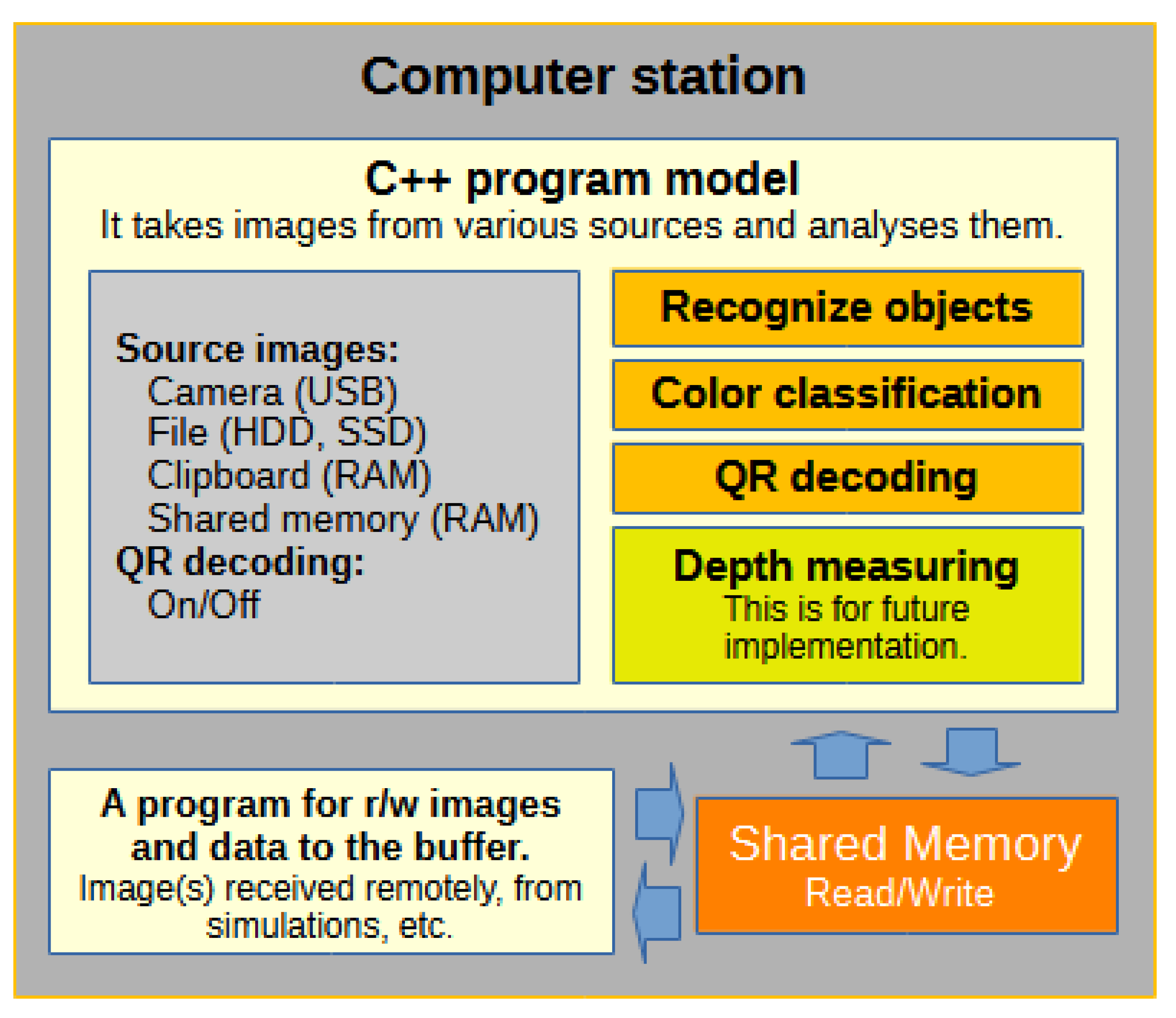
Figure 2.
Block diagram of the program model.
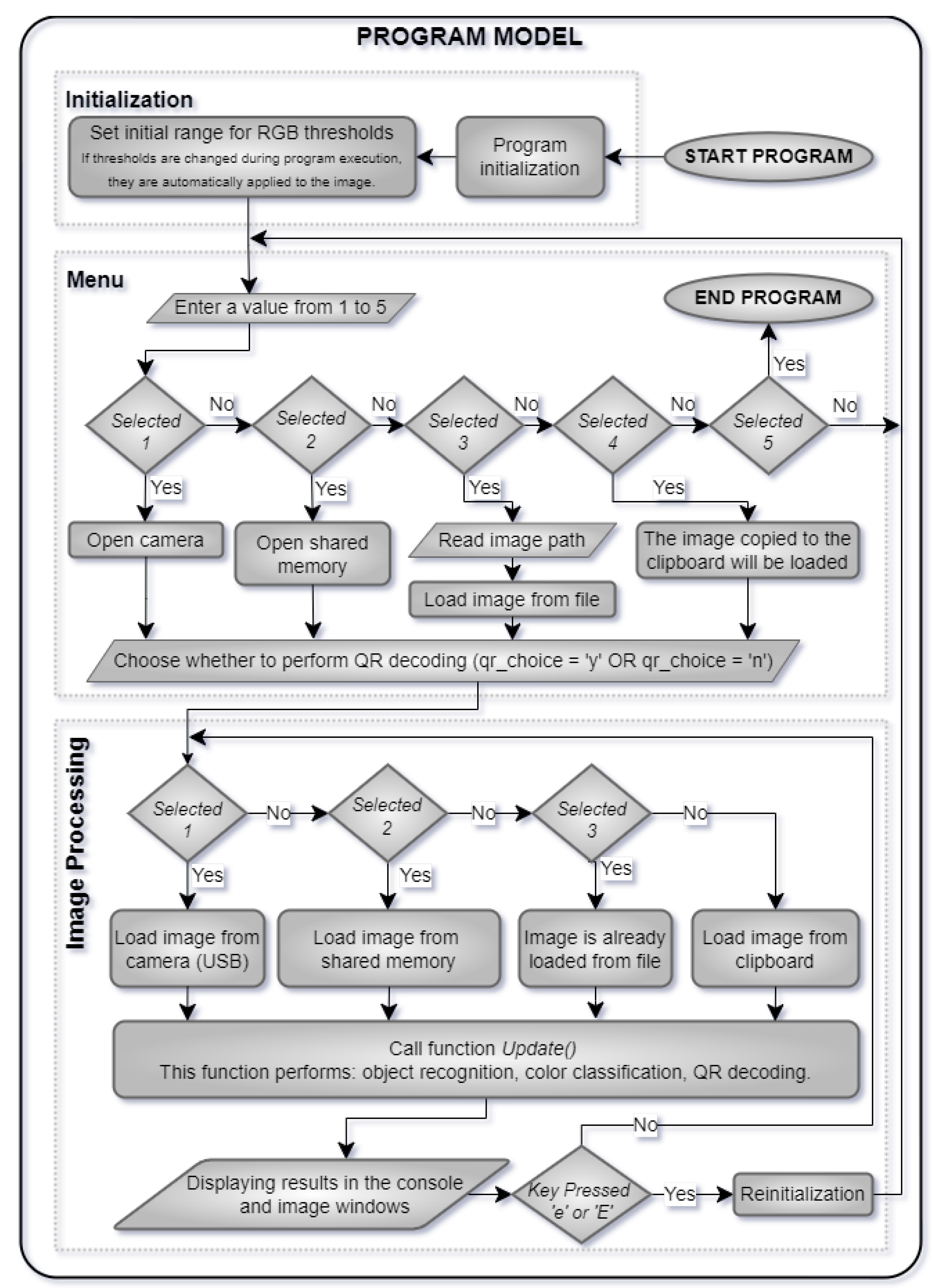
Figure 3.
Trackbar for setting color thresholds.
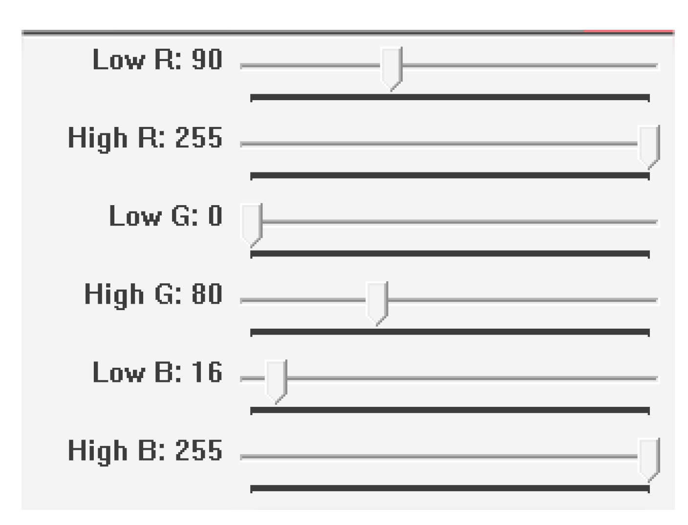
Figure 4.
RGB_3D_Color_Matrix with the first few color values.
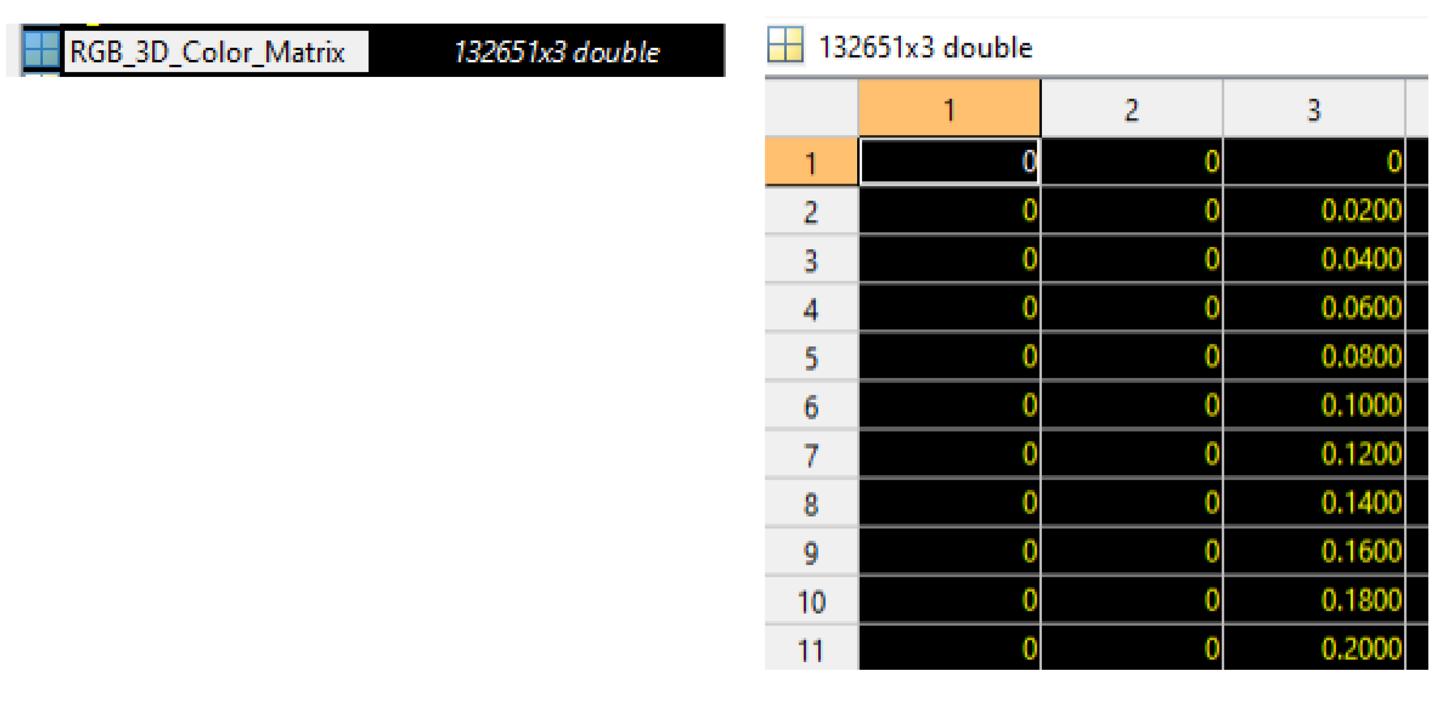
Figure 5.
Two-dimensional rgb space.
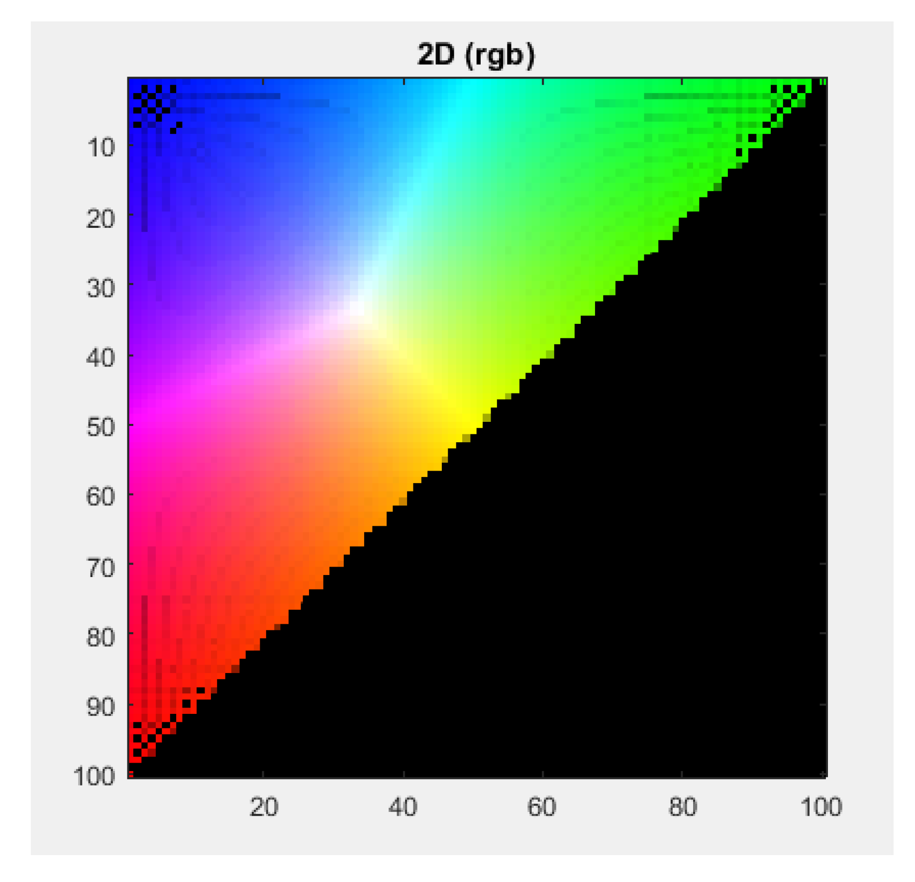
Figure 6.
Indexing of r and g coordinates.
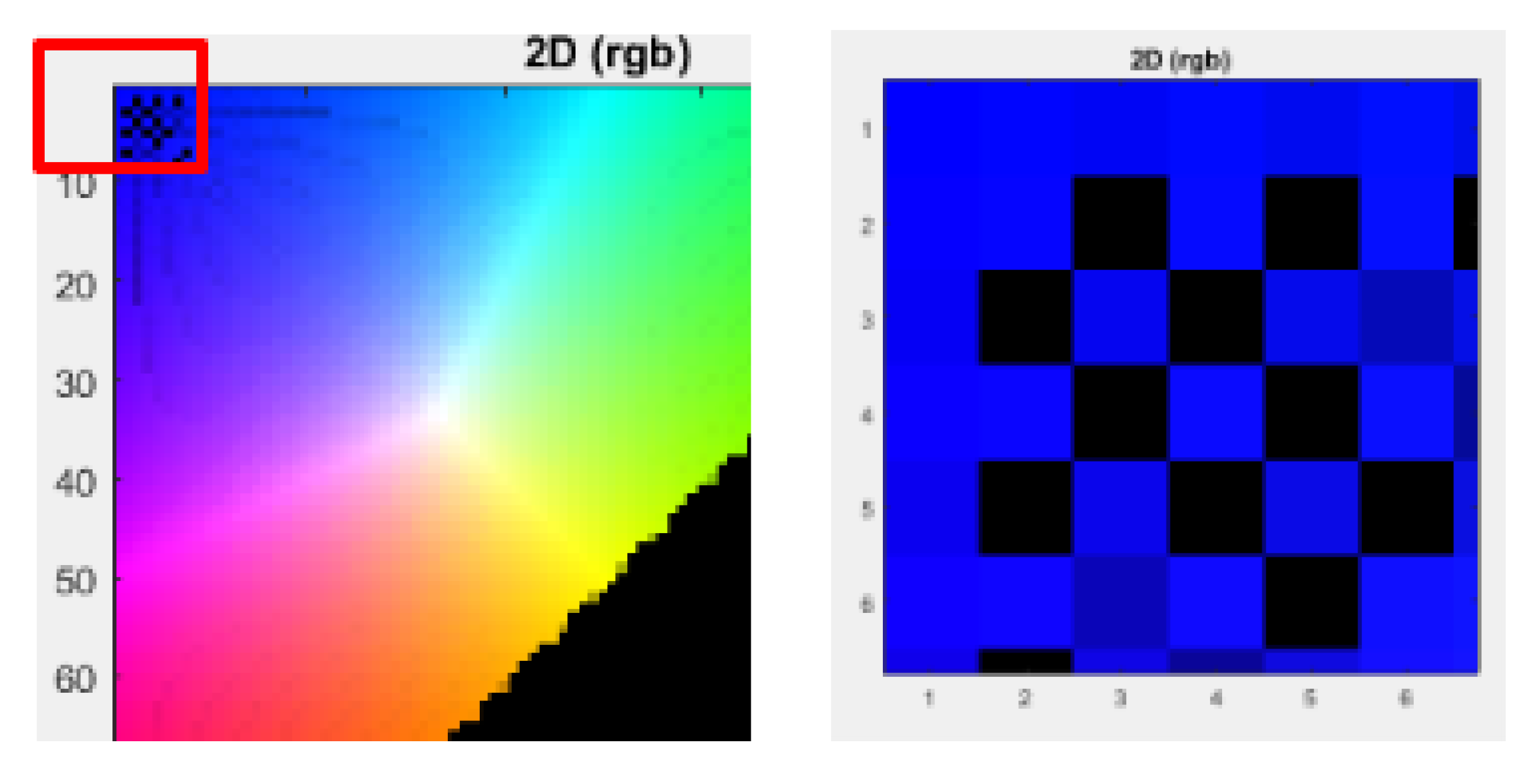
Figure 7.
Lines drawn in the two-dimensional rgb space.
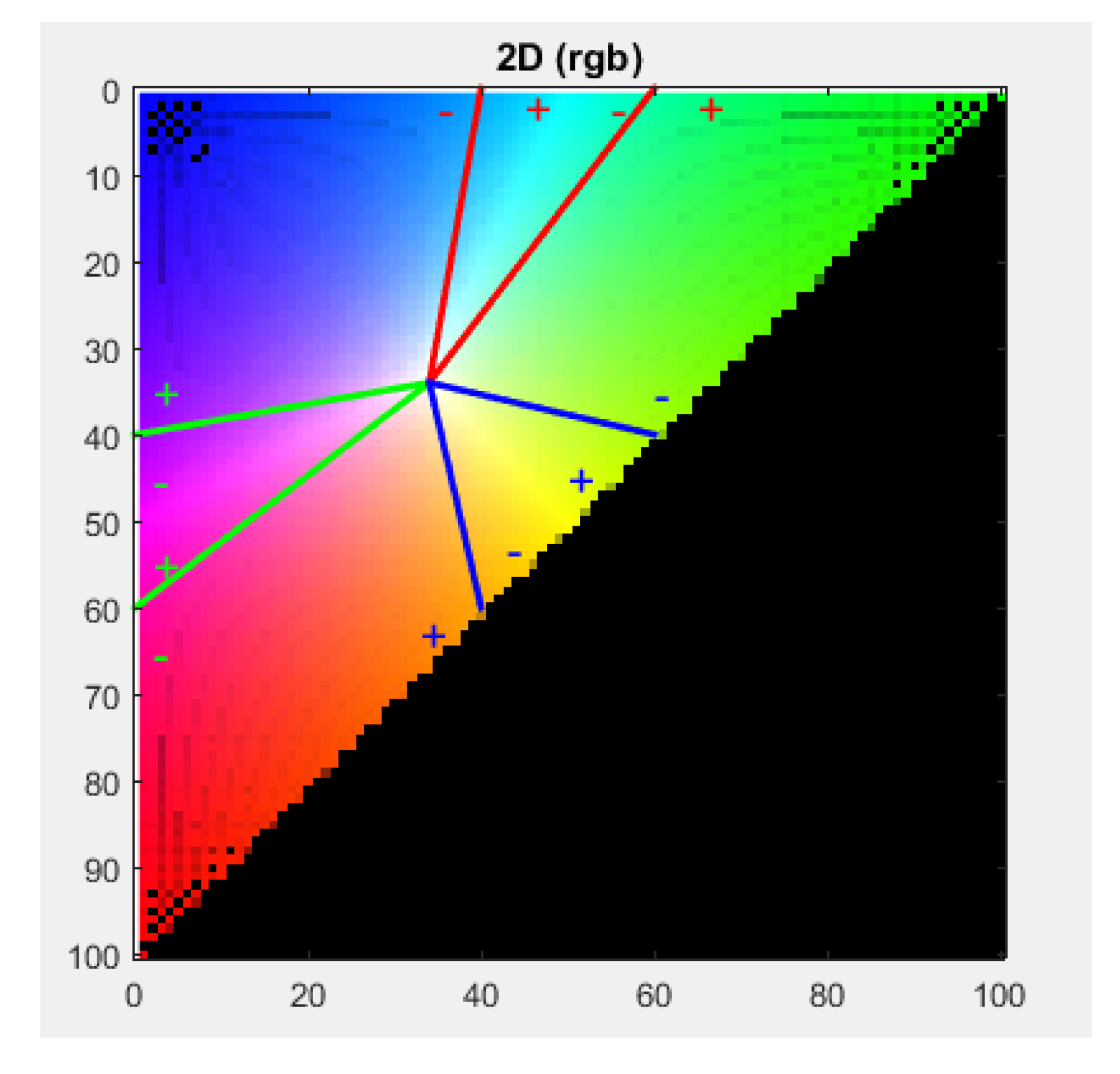
Figure 8.
Test with an object of red color and the obtained result.
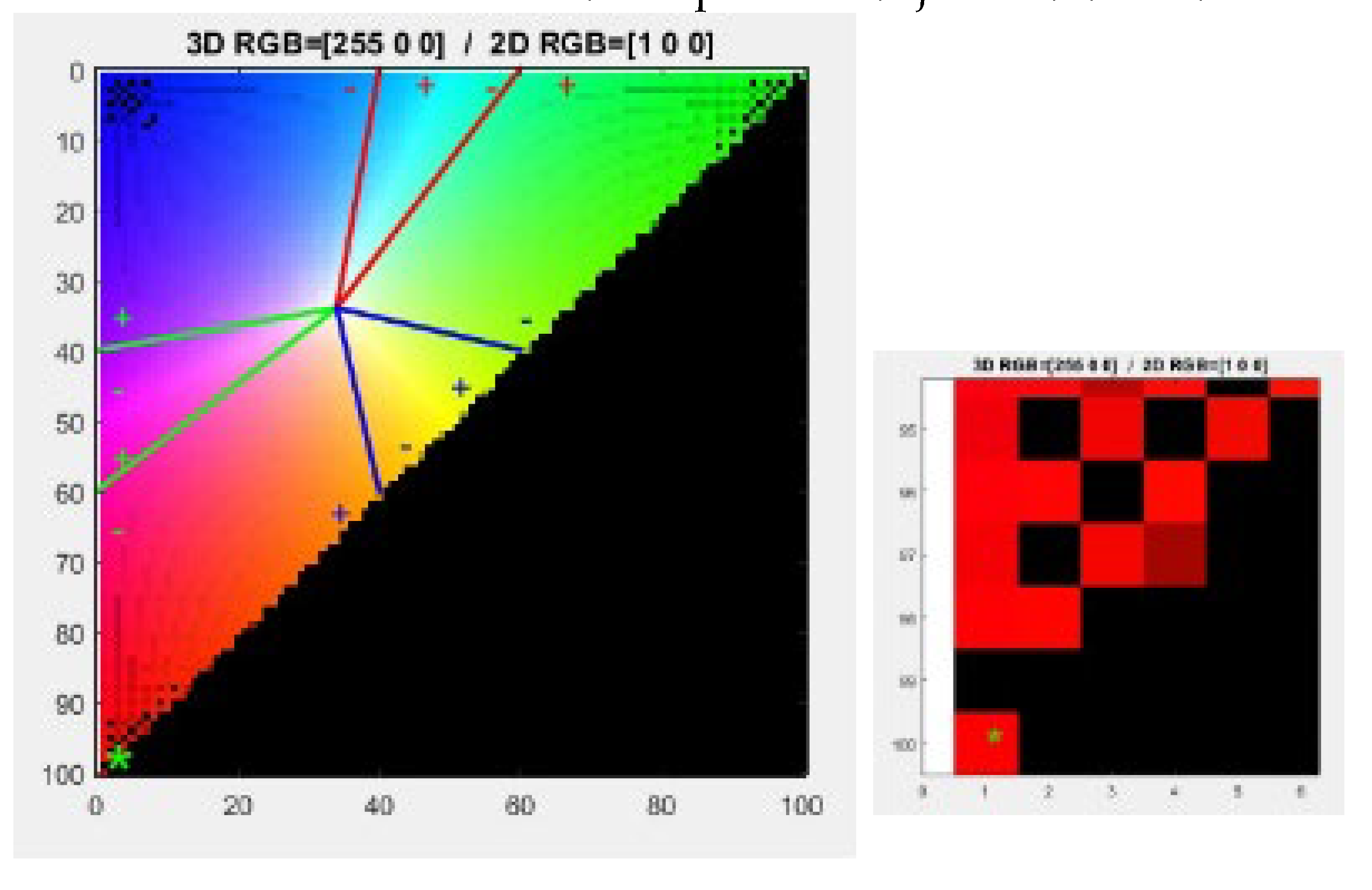
Figure 9.
Test with an object of yellow color and the obtained result.
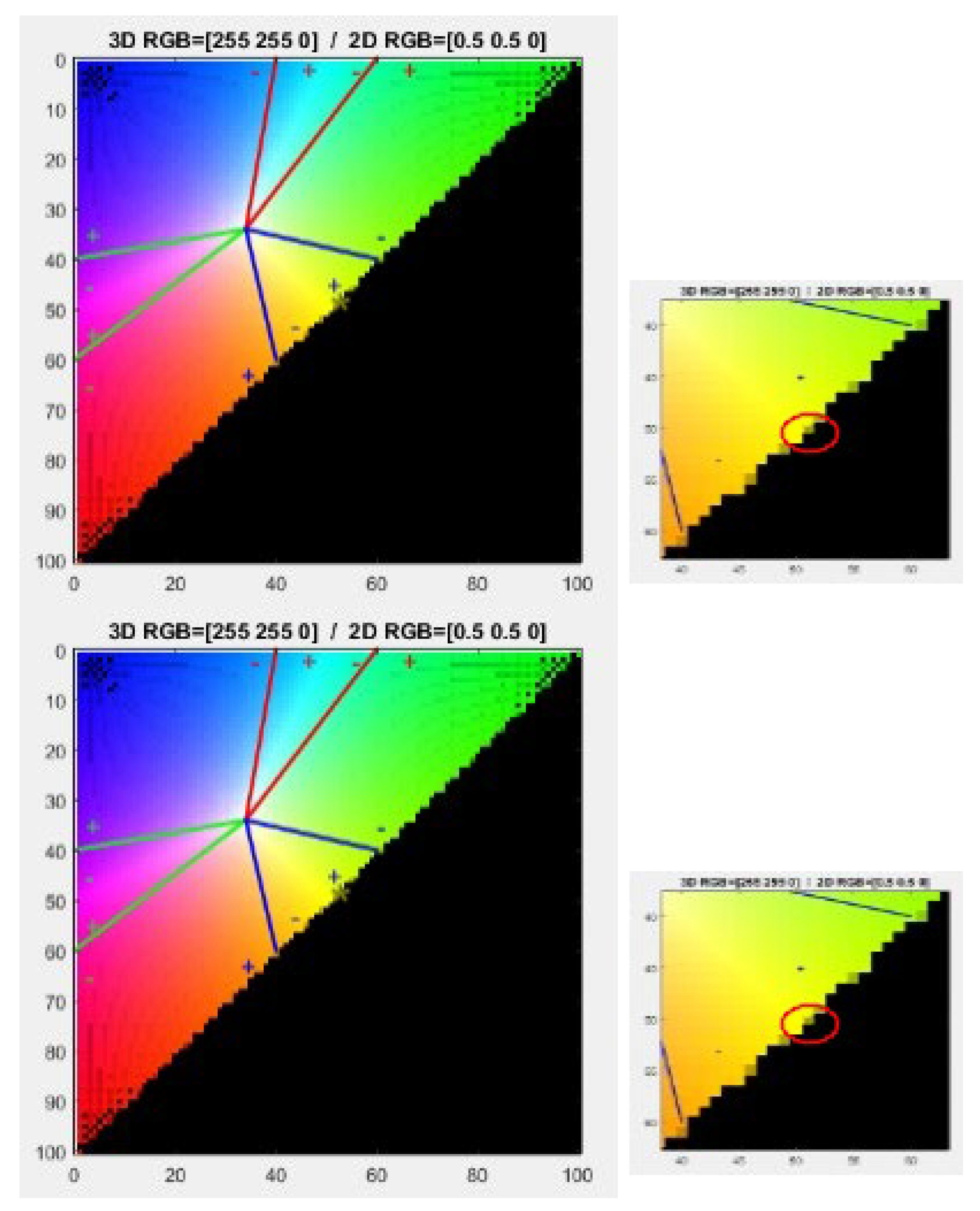
Figure 10.
Selection menu.
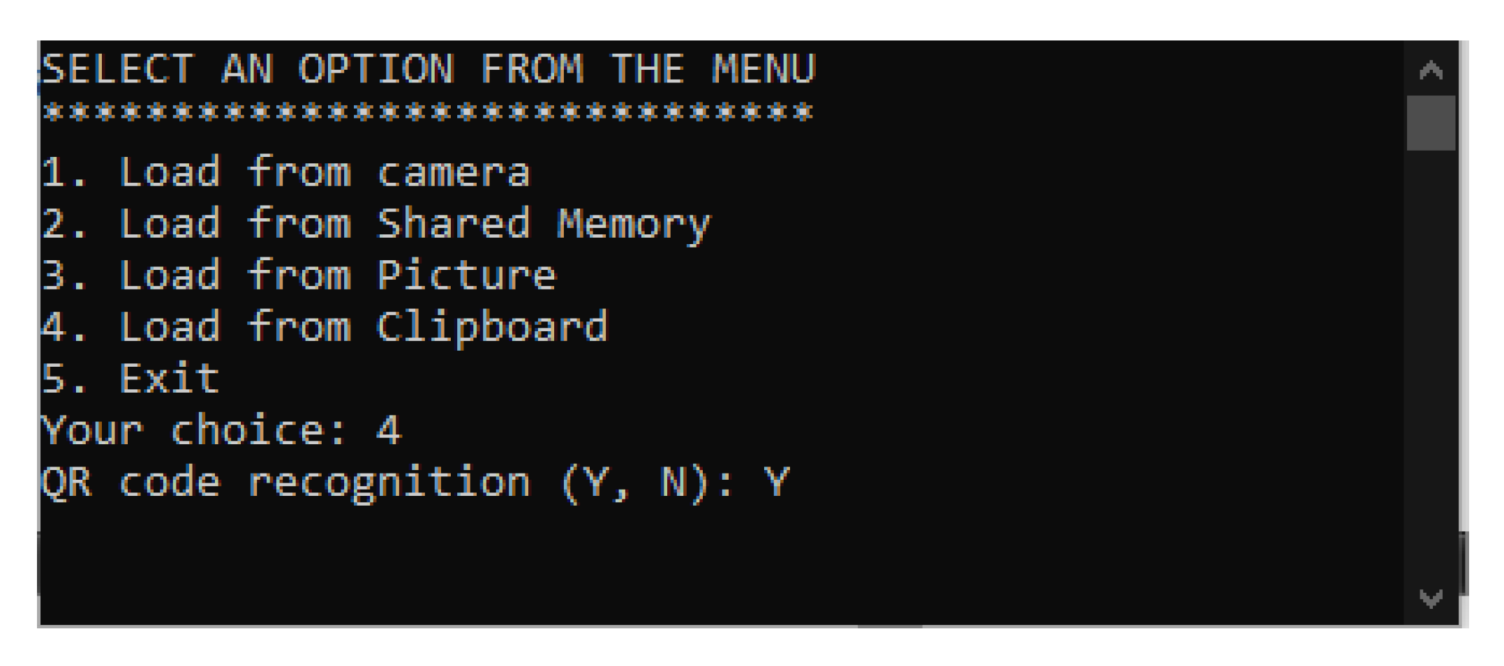
Figure 11.
ESP32CAM WiFi camera used for research purposes.
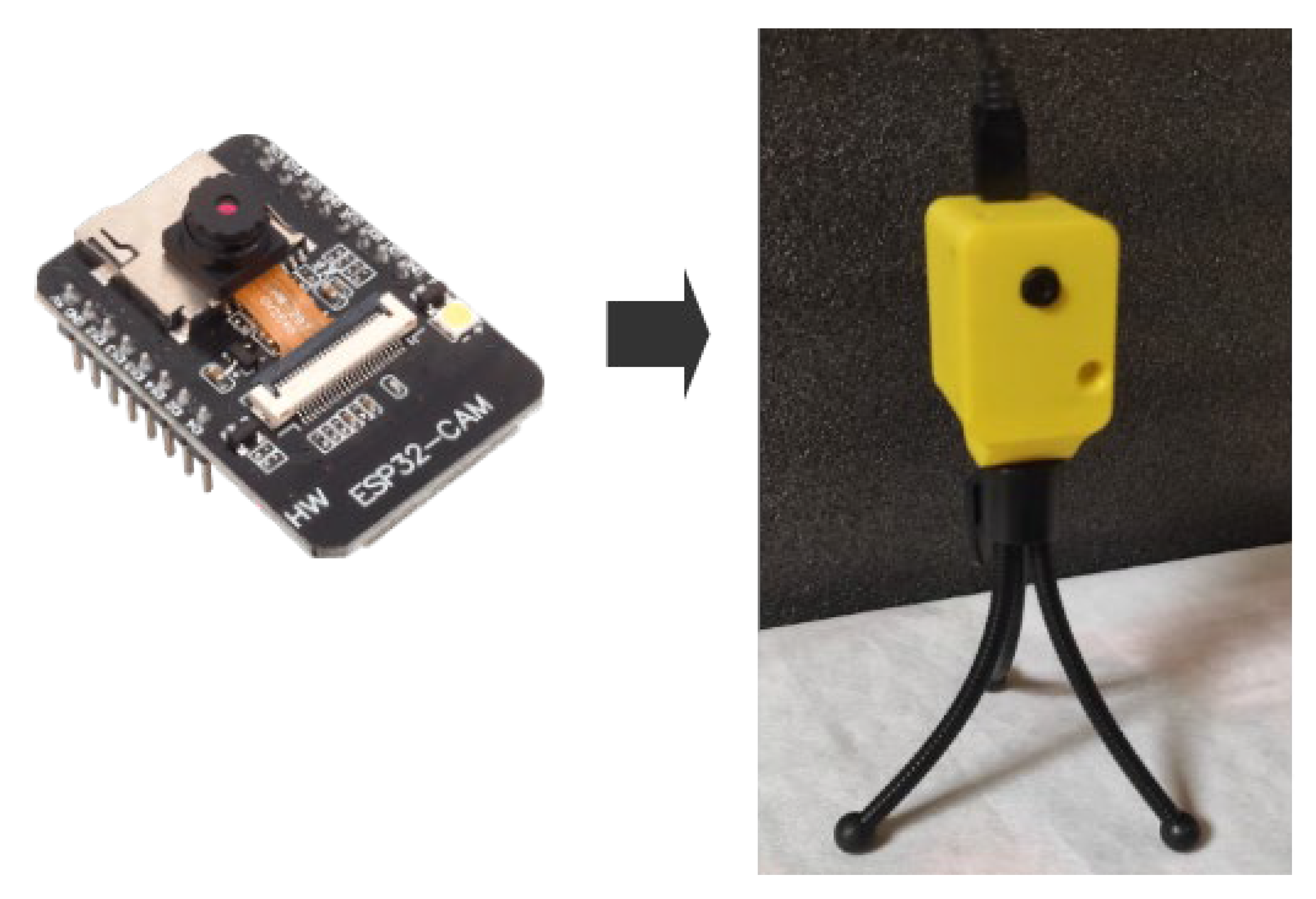
Figure 12.
Results: Option 2 (left column) and Option 4 (right column).
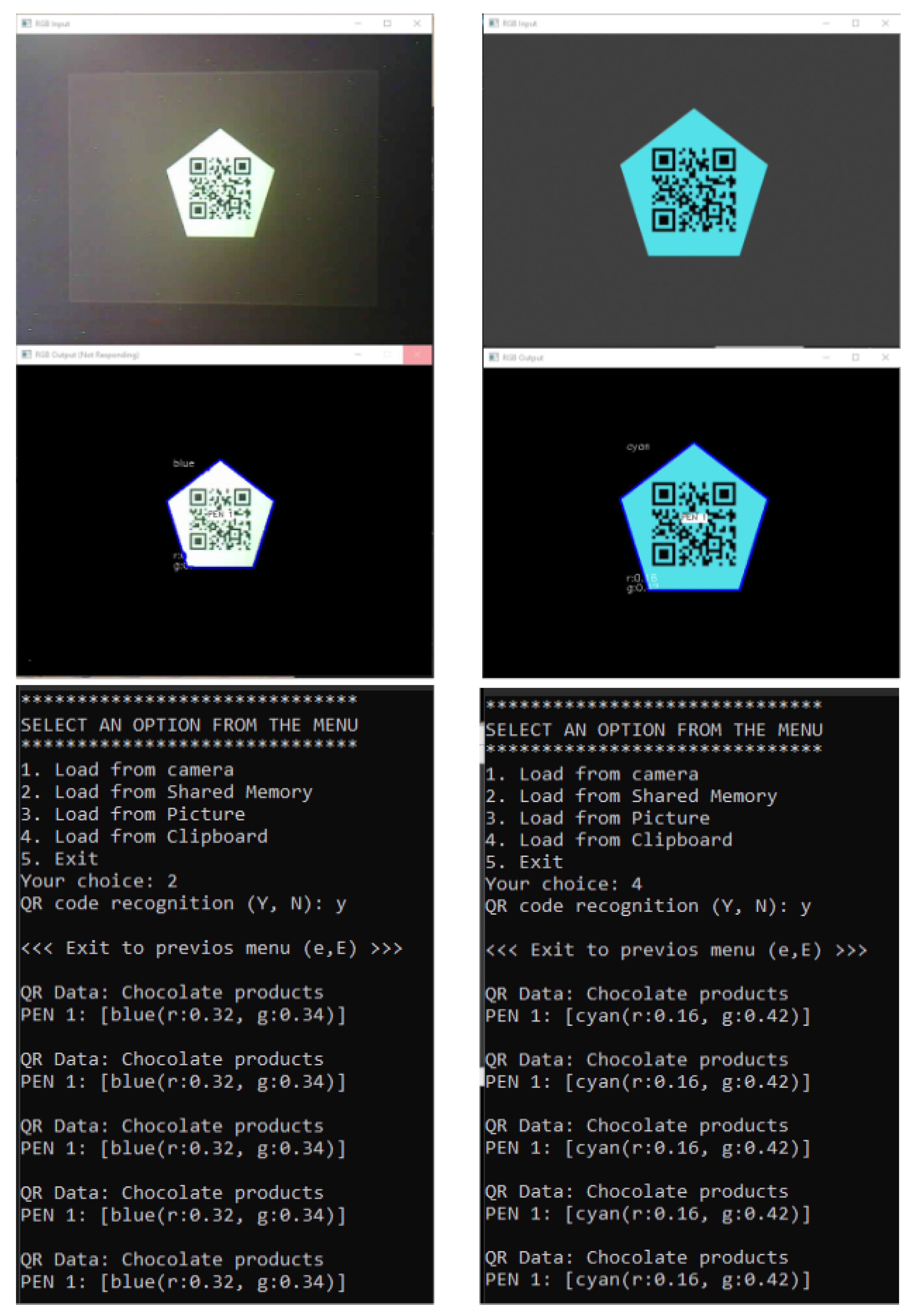
Figure 13.
Enlarged view of the recognition result for the identified pentagon.
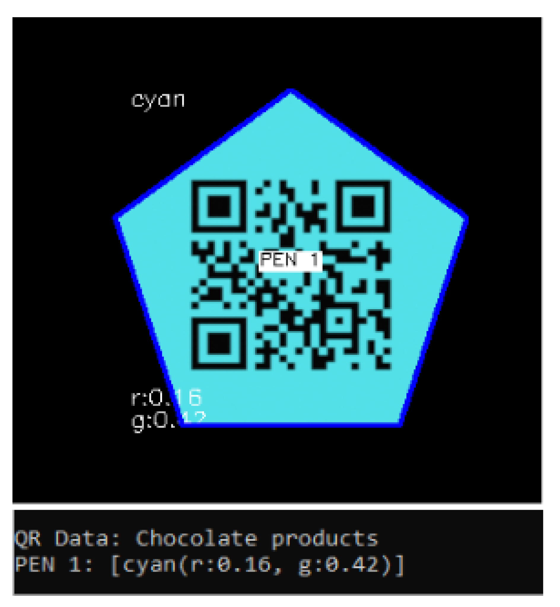
Figure 14.
Results from the program (program model) for various objects.
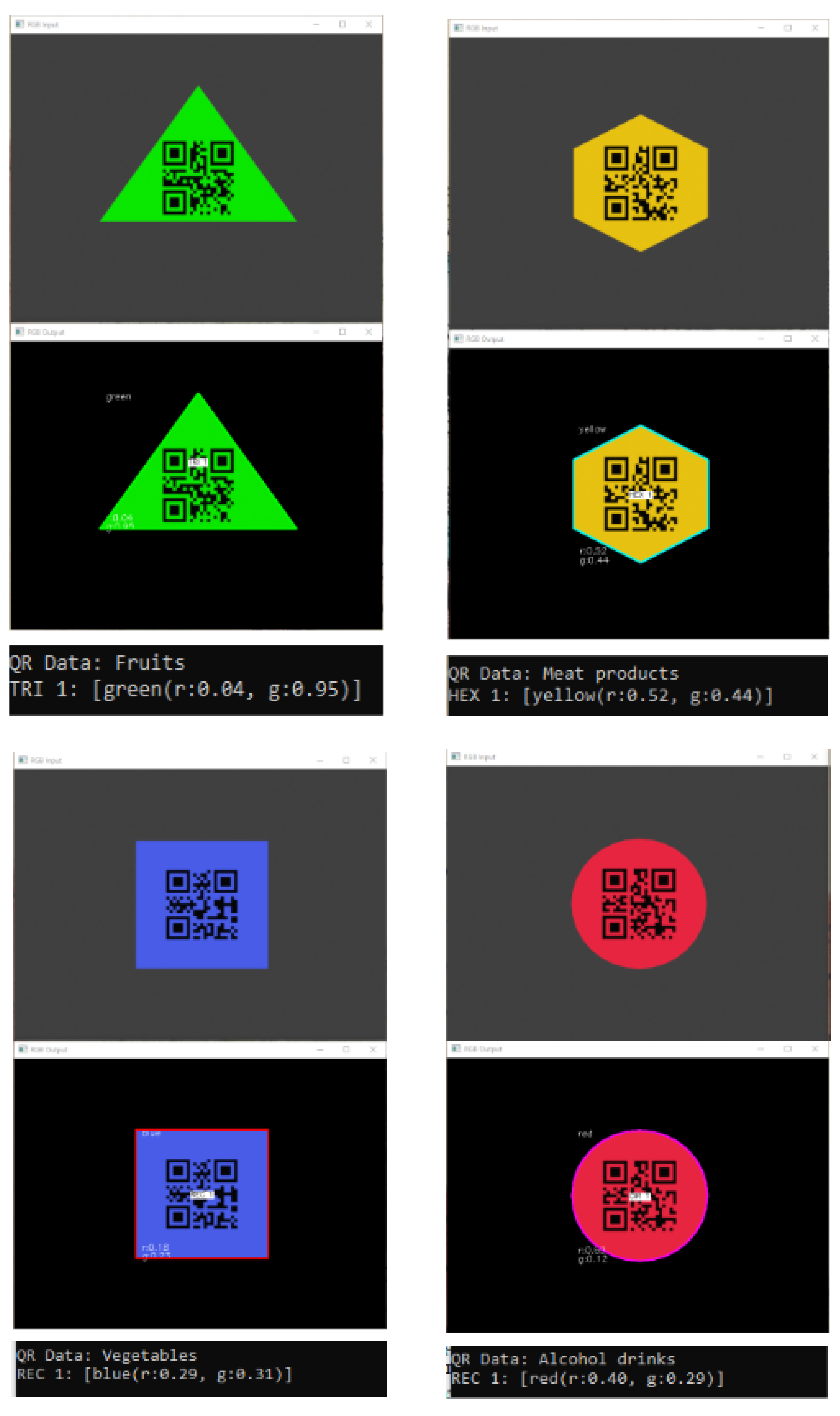

Table 1.
Integration possibilities of the program model with additional sensors.
| Function | Application | Integration scenarios |
|---|---|---|
| Determination of geographic position | Using GPS modules to accurately determine the location of the robot on a global scale. | Using a GPS module to determine the current geographic position of the robot. When certain objects are recognized, their coordinates can be saved, which can be useful for creating maps and specifying specific points on those maps. |
| Orientation and navigation in space | Using inertial motion (accelerometers) and rotation (gyroscopes) sensors to read the robot's orientation and motion. | Using the output information from the sensors (gyroscope and accelerometer) to determine the orientation and navigation of the robot. Upon recognition of certain objects, the robot can automatically navigate the environment and take appropriate actions. |
| Obstacle detection, distance measurement to objects | Using distance sensors such as ultrasonic and infrared to measure the distance to nearby obstacles. | Using ultrasonic or infrared sensors to measure the distance to nearby objects. In object recognition, the measured distances are used to optimize navigation or prevent collisions. Dynamic response and actions by the robot according to the recognized objects (obstacles). |
| Measurement of physical parameters in the environment | Using sensors to measure temperature, humidity, illumination and other physical parameters. | Using sensors to measure temperature, humidity, atmospheric pressure and other physical parameters in the environment. When certain objects are recognized, an analysis can be made for their possible effects on the robot or the environment. |
Disclaimer/Publisher’s Note: The statements, opinions and data contained in all publications are solely those of the individual author(s) and contributor(s) and not of MDPI and/or the editor(s). MDPI and/or the editor(s) disclaim responsibility for any injury to people or property resulting from any ideas, methods, instructions or products referred to in the content. |
© 2024 by the authors. Licensee MDPI, Basel, Switzerland. This article is an open access article distributed under the terms and conditions of the Creative Commons Attribution (CC BY) license (http://creativecommons.org/licenses/by/4.0/).
Copyright: This open access article is published under a Creative Commons CC BY 4.0 license, which permit the free download, distribution, and reuse, provided that the author and preprint are cited in any reuse.


