
Submitted:
17 September 2024
Posted:
18 September 2024
You are already at the latest version
Abstract
The use of educational robotics has become increasingly popular in STEM education, offering motivating and hands-on learning experiences. This paper explores the potential of educational robotics for teaching plane curves at the university level. Specifically, it investigates the development and implementation of a LEGO SPIKE Prime robot designed to draw various central trochoids, including epicycloids and hypocycloids. The robot’s construction and programming are described, emphasizing the relationship between the robot’s physical movements and the mathematical equations of the curves it produces. The study also examines the integration of dynamic geometry software, which allows for visualization of the curves and verification of the robot’s accuracy. The paper concludes that educational robotics can serve as a valuable tool for enhancing both theoretical and practical understanding of mathematical and engineering concepts, offering a more engaging and interactive approach to learning.
Keywords:
educational robotics
; STEM-based education
; LEGO robotics
; central trochoids
; drawing devices
; higher education
1. Introduction
Incorporating sustainability into pedagogical approaches is a top priority for higher education institutions [1]. STEM (Science, Technology, Engineering and Maths) education is one of the tools that can provide the basic knowledge and skills needed to tackle sustainability challenges. STEM-based education promotes creativity and experimentation while fostering critical thinking and problem-solving abilities. In the real world, each STEM discipline does not function in isolation since complex and multidimensional problems are shared across several fields. STEM-based education allows students to apply knowledge and concepts from various disciplines in an integrated manner to address real-world challenges. Additionally, students can actively engage in learning activities that promote hands-on experiences and connect their work to real-life issues. This approach encourages them to seek a deeper understanding of the activities they are involved in [2,3]. Meaningful and well-designed STEM projects play a crucial role in enhancing learning and student engagement. When students engage in hands-on projects, they can see how abstract scientific principles, mathematical theories, or engineering concepts manifest in practical scenarios. Well-designed STEAM projects often incorporate elements of inquiry-based learning, which emphasises the importance of asking questions and conducting investigations. This approach not only promotes engagement but also cultivates a sense of curiosity and creativity in students. STEM projects serve as valuable platforms for students to cultivate a sustainability mindset. By integrating scientific exploration with practical applications and ethical considerations, students are better prepared to address the pressing challenges and contribute to a more sustainable future [1,4].
Robotic activities in education are essential in sparking interest in STEM and encouraging students to learn about technology [5]. Robotics in Education (RiE) is an instrument that involves students in the process of scientific and technological creativity and the development of technological knowledge. In addition to technology-related competencies, RiE also develops soft skills (e.g. communication and teamwork) [6]. As one of the sub-areas in RiE, Educational Robotics (ER) aims to improve the learning experience of people through the creation, implementation, improvement and validation of pedagogical activities, tools and technologies, where robots play an active role [7,8]. Educational robotic applications are generally effective in terms of the academic achievement scores of students [9].
According to Alimisis and Kynigos [10], and Eguchi [11], the use of robotics in education can be divided into three main categories: robotics as a learning object, robotics as a learning tool, and as a learning aid. In the first group, the focus is on robotics-related subjects such as robot programming, robot construction and artificial intelligence [12]. Robots as learning aids are social robots, robot tutors, or similar applications, where the crucial factor is interaction with humans. Robotics as a learning tool supports teaching other subjects, mainly based on robotic kits that are used to build demonstration tools in different educational situations. Models built from elements of the increasingly widely available robot kits appear in physics experiments and chemistry labs, often helping students understand mathematical concepts and even supporting the teaching of geography and history [13,14,15,16].
Visualization is very important in most areas of mathematics education and is essential when discussing functions and planar curves. Throughout the history of mathematics education, many demonstration tools have been developed to illustrate curves, and in the 21st century, teachers can even use robots to draw curves [17,18,19]. Building and programming drawing robots are motivating and fascinating for students interested in both engineering sciences and the arts. It requires both hardware and software skills, computer programming is linked to mathematics in an easy-to-understand way, and the results are physically tangible in the form of attractive geometric patterns.
In this article, we present a prototype of a LEGO robot that can be used for educational purposes to study the members of a special family of curves, the central trochoids, and to draw a variety of curves from this group. Trochoids are often referred to as spirograph curves since most of the curves created with the popular Spirograph toy belong to the family of trochoidal curves [20]. However, other types of curves can also be generated by Spirograph and most of the trochoidal curves cannot be drawn by Spirograph [21]. The family of central trochoids contains many curves that are important in physical phenomena and engineering practice. Working with the robot, students will gain first-hand experience of these curves while learning about their fundamental properties and mathematical background.
We could not find any references in the literature on the mathematical investigation and application of similar drawing robots in education, so we consider the robot presented in this paper and the related experiences to be up-to-date and novel.
1.1. Overview of Devices Drawing Spirograph Curves
Spirograph curves can be derived by rolling a curve along another curve without slipping. The earliest drawing instruments, as well as the Spirograph, use gears to ensure non-slip rolling. In 1752, Suardi invented the geometric pen or ellipsograph, an instrument by which it is possible to draw more than 1200 geometric figures, many of them taking the shape of flowers. This invention was later perfected by many others. Ibbetson was inspired by Suardi when he created his mechanism, the Geometric Chuck, which is a lathe-like tool designed for making ornately decorated objects [22]. Plant’ Chuck and Holtzappffel’s Geometric Chuck are similar but more advanced devices also from the 19th century [23]. Regardless of their practical application, the various drawing devices were very popular in the Victorian era. Among these, spirograph curves could be produced with the help of circular harmonographs. The most complex such apparatus was Rigge Creigthon’s machine, with which, according to the inventor’s calculations, more than 7.6 billion different curves could be made [24]. After the turn of the 20th century, drawing machines became available to the public. The Wondergraph, a drawing toy for children, has been mass-produced since 1908. This was followed by the Hoot Nanny and Mechanograph versions, also aimed at a younger age group, which can be considered as the direct predecessors of the Spirograph toy. The Spirograph, one of the best-known and worldwide drawing toys, was patented in 1965 by the British engineer Denys Fisher. This game has enjoyed unbroken popularity ever since, and not only children but also adults enjoy creating spectacular patterns by using the plastic gears.
In addition to entertaining children, Spirograph-like toys can also be used for educational purposes. In the 1911 Schilling catalog, there were two gear-based kinematic models that could be used to study the generation mechanism of different types of central trochoids [25]. Although these tools can nowadays only be studied in museums, today’s teachers have the opportunity to choose from a number of digital solutions for simulating the operation of mechanical drawing machines. Students experienced in programming can easily write graphical animations themselves, but anyone can download and use ready-made spirograph applications created with GeoGebra, Desmos or other dynamic geometry software. These spectacular moving animations are undoubtedly excellent demonstration tools for illustrating the curve generation process, but they obviously provide a less physical experience than picking up and using a mechanical device.
1.2. Drawing LEGO Robots
LEGO Education robot kits can be used at all levels of education to teach programming, robotics and computational thinking, and to show the connections between interdisciplinary content [26,27,28]. A re-programmable robot kit, such as LEGO, is a great way to build a structure capable of automatic drawing. Figure 1 shows several drawing mechanisms built from different LEGO kits. In Isogawa’s book [29], other drawing robots operating on various principles are found with detailed building instructions.
A common feature of these robots is that the drawing is made on a sheet of paper by a pen attached to the robot or robot arm, and then the pen or the robot (or both) makes some movements. Even more complex designs can be created by moving the sheet of paper itself, attached to a turntable. Like the Spirograph toy, the robots that draw curves and various spectacular patterns are designed primarily for entertainment. The equations and properties of the curves displayed are usually not investigated, and therefore, these robots are less suitable for educational purposes. One of the most important aspects of our work was to be able to mathematically characterize the drawings after studying and describing the robot’s movements.
1.3. Parametric Equations of Central Trochoids
A roulette is a general type of plane curve, defined by the path of a point attached to one curve as that curve travels along another fixed curve. Depending on the type and location of the curves, many important curves can be derived as a roulette. If the fixed curve is a straight line and the moving curve is a circle, then the path of the examined point is called a trochoid. As a special case of trochoids, a cycloid is a curve that is generated by a point on the circumference of a circle as it rolls along a straight line. If we fix a circle instead of a line, and another circle is rolled around it, then a point attached to the rolling circle traces an epitrochoid or a hypotrochoid, according to the circle rolls on the outside or inside of the fixed circle. If the tracing point is on the circumference of the rolling circle, the curve traced is called an epicycloid or a hypocycloid, respectively. It should be mentioned that there is no complete agreement in the literature on the term trochoid. Some of the authors use this term encompassing epitrochoids and hypotrochoids [21,30], while others restrict the term trochoid, as mentioned above, to the case where a circle rolls along a line. To avoid confusion, after Hotton [31], the term central trochoid will be used for the common term of epitrochoids and hypotrochoids.
For generating the parametric equations for central trochoids, assume that the centre of the fixed circle is at the origin, R is the radius of the fixed circle, r is the radius of the rolling circle, and d is the distance from the centre of the rolling circle to the tracing point. In the following, the fixed circle is sometimes referred to as the base circle, and the rolling circle is the generating circle. The tracing point is often referred to as the pole, and we call the value d pole distance. It can be proved (see, for example, Lawrence [32]) that in the case of epitrochoids, the parametric equations are
and for the hypotrochoids are
where, in both cases, the changing parameter is the counterclockwise angle from the positive x-axis to the line joining the centres of the two circles. The numbers R, r, and d will be referred to as the parametric constants. In Figure 2, all variables of the central trochoid generation process are indicated. According to the geometrical interpretation of central trochoids, R and r are positive real numbers, and d is a non-negative real number.
1.4. Types of Central Trochoids
Depending on the relationship between d and r, three main types of central trochoids can be distinguished. If , that is, the tracing point is on the circumference of the rolling circle, we obtain an epicycloid or a hypocycloid. If , we have a curtate epitrochoid or a curtate hypotrochoid. In case of , the name of the obtained curve is a prolate epitrochoid or a prolate hypotrochoid. In addition to this grouping, further important curves can be obtained by a particular choice of parametric constants. For example, if , it can be easily seen from equations 1 and 2, that the obtained curves are circles with radius and ( is assumed). Further examples can be found in Table 1.
2. Materials, Goal and Methodology
We aimed to design drawing tools to allow university students to visualize central trochoids. To achieve this goal, we chose the LEGO Education Spike Prime robot set, developed specifically for educational purposes and launched in 2020. The kit comes with a range of teaching materials and activities that guide children through different STEM concepts and problem-solving challenges. Although the target audience is the 10-15 age group, university students can also be given challenging tasks. Designing and operating a trochoid drawing robot is one such task for which several possible solutions exist. First, we refer to our two previous models, the Spirograph-like and the SCARA-type robot. Although these models are based on different principles, they were both designed to draw certain trochoidal curves and they perform this function, subject to certain restrictions.
2.1. The Spirograph-like Model
The most obvious approach to designing a drawing robot is to start from the definition of central trochoids and model the motion of the generating circle on the base circle. To achieve non-slip rolling, circles are substituted by gears, and a drawing instrument is attached to the rolling gear to move together with it. A device based on gears and inspired by Schilling’s kinematic models is presented in [17]. This dual-function structure is equipped with gears on both sides and is suitable for imaging both epitrochoids and hypotrochoids (Figure 3). The built-in gears correspond to the fixed circle in the definition so that we can provide variation by varying the size of the generating gear and the pole distance. However, the available gear sizes will limit our possibilities, especially for hypotrochoid drawing, where a large circle with teeth on the inside is required. The most suitable standard LEGO parts for this purpose are the curved gear racks, of which four can be assembled to make a base circle with a radius of 70 mm. This means that we cannot produce the ellipse and astroid shown in Table 1 since there are no standard LEGO gears with a radius of 35 mm or 17.5 mm to model the generating circle.
2.2. The SCARA-Type Robot
Instead of using gears, a completely different approach to the problem is to rotate the drawing head and the entire robot around its axis. Such a simple construct was presented in [18]. The main novelty of the robot was that, although the distance between the rotation axes was given by the design, the curves that could be drawn were varied because they could be parameterised by the rotation speed of the pen and the robot relative to each other. We named this LEGO robot the SCARA-type robot (Figure 4), after industrial robots with rotary arms. However, the disadvantage was that the robot had to be placed on the sheet of paper it was drawing on, so it could only draw around itself, which meant there was always an empty dead zone in the middle of the sheet of paper. In addition, the structure was not completely stable, so it tended to move a bit, especially when the motors started suddenly, which resulted in less accurate figures.
An additional disadvantage in the case of both presented models was that, due to the constructions, the writing instruments had to be cut to size to fit into the pen holder. We usually used felt-tip pens to make the drawings, so the pens could not be used for long after they were cut, as they dried out quickly. Despite these drawbacks and inconveniences, the students were mostly very enthusiastic about working with the robots and welcomed the practical approach to the topic of plane curves [19,33].
2.3. The Aim of the Research
In testing our previous robot models, we have found that students find learning with robots innovative and motivating, which also helps them to understand mathematical concepts. Despite the positive feedback from students, we were not fully satisfied with the applicability of our robot models, due to their limitations and shortcomings.
The aim of our work was to create a new, easy-to-use, universal robot that can draw more and more different central trochoids than its predecessors. We also aimed to eliminate as much as possible the drawbacks of our previous robots. We wanted to coordinate the robot’s operation with dynamic geometry software, so that the equations of the drawn curves could be easily identified and verified. The robot is primarily intended for educational purposes, to give students a tool that makes learning mathematics fun and motivating.
2.4. Methodology
The V-model is a structured and sequential approach to software development, widely recognised for its clarity and comprehensiveness. Figure 5 shows the phases of the model. In the V-model, there are two approaches to development processes. As a top-down approach, it expresses the design process from top to bottom in the left branch of Figure 5, while the testing process is bottom-up in the right branch. The V-model is a variation of the traditional Waterfall approach. Unlike the Waterfall methodology’s linear, cascading phases, where each stage flows directly into the next, the V-model implements a parallel testing phase for each development phase [34,35]. Although originally a software development method, the V-model has also proven to be a suitable way to control the development process of the drawing robot. By applying it, the stages of development were structured, organised and controlled. This approach promoted clarity, facilitated error reduction and supported an efficient development process.
The initial concept stage of the development was the requirement analysis, which focused on defining the precise requirements for the drawing robot. Key aspects to consider include the following:
- a)
- Drawing capabilities: The robot should be able to draw various central trochoid curves, encompassing epitrochoids (curtate and prolate), hypotrochoids (curtate and prolate), including specific curves like circles, limaçons, cardioids, nephroids, astroids, and rhodonea.
- b)
- Accuracy: The robot should strive to produce drawings that closely match the mathematical definitions of the curves, minimising any discrepancies.
- c)
- User-friendliness: The robot should be easy to operate and program, catering to both educators and students.
- d)
- Cost-effectiveness: The materials and components used in constructing the robot should be readily available, and the overall cost should be kept within reasonable limits.
The preliminary design phase, focused on detailed planning for both hardware and software components:
- a)
- Define the robot’s frame with suitable dimensions and stability.
- b)
- Design the drawing head mechanism, encompassing the pen holder, motors, and movement mechanisms.
- c)
- Design the rotating tray mechanism to ensure accurate rotational movement.
- d)
- Select components (LEGO elements, motors, sensors) and outline the assembly plan for the mechanisms.
- e)
- Design the robot’s control program to enable the drawing of various curves. Include settings for adjusting parameters to control curve variations.
- g)
- Ensure user-friendly programming and testing capabilities, and utilize the LEGO SPIKE Prime software for programming.
The implementation phase, the critical design phase of the V-model, involved building and coding the robot. The robot was meticulously built using selected parts (LEGO elements). The assembled units have been carefully integrated to create a robust and functional robot. Hardware validation was performed, i.e. the robot hardware was rigorously tested to verify its stability, functionality and the correct functioning of all mechanical parts. The integration and test phase ensured that all robot parts, from the mechanical structure to the software, work together harmoniously. The testing included three parts. During the functional testing, we verified that the robot can accurately draw all planned curves without errors. The performance testing assessed the robot’s speed and precision in the drawing, and the usability testing was to evaluate the robot’s ease of use and programmability for the target user group. Throughout testing, any identified issues were documented and addressed through corrective actions, ensuring a robust and reliable final product. The deployment phase marked the transition from a developed robot to a usable didactic tool. Building instructions had to be created to guide students through making the drawing robot. Moreover, instructional materials are essential for training the target audience to use the robot and its various features effectively. The robot had to be introduced to the target users, showcasing its capabilities and functionalities in a clear and engaging manner. This introduction fostered confidence and encouraged robot adoption within the intended university environment. The release phase marked the end of the drawing robot’s development process, transitioning it from a prototype to a usable didactic tool. This phase involved finalising documentation and using the robot in a classroom environment in university practice, whether for educational purposes or research applications. Ensuring a smooth release, with clear instructions and support, was essential for maximising user satisfaction and encouraging the usage of this innovative tool.
The V-model provided a robust framework for developing a drawing robot that meets both educational and technical objectives.
3. Results
Following the steps of the V-model approach and building on the experience with Spirograph-like and SCARA-type models, we developed a robot that eliminates the shortcomings of the previous models. The new model is closer in principle to the SCARA-type, but more stable and capable of representing a much wider range of curves. In the following, we describe in detail the architecture, the operating mechanism and the programming of the new robot model.
3.1. Description of the New Universal Robot Model
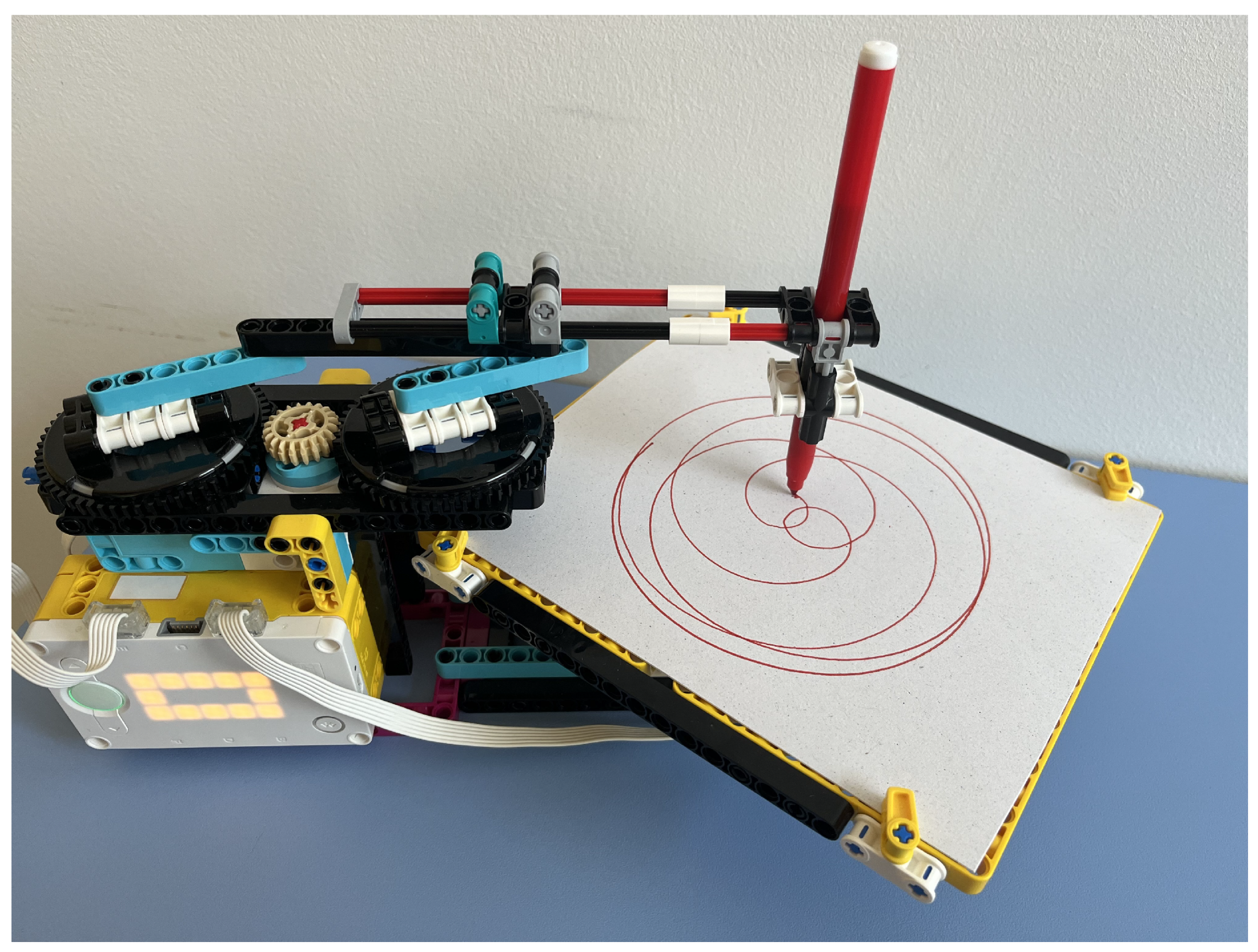
Similar to the SCARA-type robot, the operating principle of the new model is based on a combination of two circular movements. However, a significant innovation is that this time, the robot remains fixed, and instead of rotating the whole robot, a tray is rotated on which we attach a sheet of paper. An arm extends above the tray, at the end of which there is a holder suitable for receiving a writing instrument. The felt-tip pen can be easily and simply slipped in here; it has to be lowered enough so that the tip touches the paper sheet. In this case, no cutting is necessary; the entire felt-tip pen can be placed in the holder; other elements of the construction do not prevent it from moving freely. We had to make the pen holder move in a circular motion over the tray. We solved this by mounting the holder on a beam, which is attached to two gears that rotate at the same time so that the section connecting the attachment points is parallel and of equal length to the section connecting the centres of the gears. Figure 6 shows the final model picture of the new robot with the main components and see also Figure 11, which shows the completed model in operation.
The pen placed at the holder performs a circular movement, with a radius as large as the distance between the attachment point of the beam and the center of the gear that supports it. This radius can be varied between 0 and 40 mm in 8 mm increments, depending on which fixing points are selected. The 8 mm step size is the distance between the centers of the holes on the LEGO pieces. We will denote this radius by d because, as will be seen later, it corresponds to the pole distance in the definition of central trochoids. The two large gears are rotated by an intermediate gear driven by a motor built into the model, while another motor is responsible for rotating the tray. The axis of rotation is right in the middle of the tray, so this point is considered the origin of the coordinate system. The x-axis of the coordinate system should be the direction defined by the pen holder arm above the stationary tray, with the positive direction towards the robot body. If the tray does not move, but the pen holder arm is rotated, it draws a circle of radius d symmetrical on the x-axis. The question is where the center of this circle lies. This depends on how far out the pen is slid on the beam; due to the construction, this distance can be adjusted flexibly within certain limits. The first coordinate of the centre of the drawn circle depends on this value; it will be denoted by u. The value u is continuously variable, typically between 0 and 40 mm. In addition to u and d, there is a third parameter that determines the pattern resulting from the combined rotation of the tray and the pen, namely the speed c of the tray and the pen relative to each other. This relative speed means that while the tray turns an angle t, the angular rotation of the pen is . Unlike the variables u and d, the value of the parameter c is specified in the code as the ratio of the speed of the two motors.
3.2. Justification of Parametric Equations
The operation of the robot must be controlled so that the tray and the pen start and stop moving in a circular motion at the same time. The direction of the rotations determines whether an epi- or hypotrochoid is obtained. In deriving the equations, assume that the tray always rotates counterclockwise, i.e. in the positive direction, and set the direction of rotation of the pen relative to this. In the case of epitrochoids, the two directions of rotation are the same, and we give the parametric equations of the circle described by the pen as follows:
where . So, we start drawing a circle of radius d centered on at the point at and continue in a counterclockwise direction. Meanwhile, the tray also starts to rotate, so the points of the circle must be rotated by angle t around the origin. The equation of the resulting curve is obtained by multiplying the circle equations by the rotation matrix:
With and we obtain the general equations of epitrochoids given in (1).
In the case of hypotrochoids, the direction of rotation of the tray and the pen are opposite. Now we give the equation of the circle described by the pen as follows:
where . Multiplying these equations by the rotation matrix we have:
In this case, the replacements and yield the parametric equations for the hypotrochoid given in (2).
3.3. Parameter Setting
Drawing with the robot requires some preparation. A sheet of paper is attached to the turning tray, and a pen is inserted into the holder so that the tip of the pen touches the sheet of paper. The holder is designed so that the pen can be inserted or removed in one movement. We need to run a code on the robot that will start rotating the tray and the pen holder at a certain speed and then stop both movements after a certain time. The parametric equations for central trochoids contain three parametric constants. Two of these (u and d) can be set manually by fixing the pen holder beam in the appropriate position, while the third parameter c, the ratio of the speed of the pen to the speed of the tray, can be adjusted in the code. The direction of rotation of the motors is also set in the code, depending on whether an epitrochoid or hypotrochoid is to be drawn. The value of the manually adjustable parameters can be chosen from a limited set due to the design of the robot. The pen holder is mounted on a LEGO Technic beam, which can be fixed to the robot in several different positions. Depending on the distance from the center of the gears that ensure the circular movement of the pen, five possible nonzero values for the parameter d are obtained. These values are 8, 16, 24, 32 and 40 mm because the possible fixing points on the LEGO elements are 8 mm apart. The parameter u indicates how far the centre of the circle described by the pen is from the origin of the tray. This distance can be flexibly adjusted on the robot between 0 and 40 mm. The value of the parameter c can also be arbitrarily specified in the code within reasonable limits. Thus, apart from d, the other two parameters can be chosen flexibly, which gives great freedom and variety in the curves that can be drawn with the robot. Table 2 summarizes the relationships between the parametric constants in Equations (1) and (2) and Equations (3) and (4) for central trochoids. The parameter d has the same value in both types of equations.
Using the formulas given in Table 2, it is easy to determine the required settings in the robot and in the code that will result in the specific curves listed in Table 1. Let’s look at two examples.
- (i)
- A cardioid is a special epitrochoid where the three parametric constants have the same value. Since . It follows that , since , we have . So we manually set d to, say, 16 mm and the pen holder so that mm. We then start the two motors at the same speed in the same direction.
- (ii)
- An astroid is a hypotrochoid with . We get . The manual settings can be mm and mm; the motors must be rotated in opposite directions so that the pen rotates at four times the speed of the tray.
3.4. Coding
The SPIKE Prime application offers a Scratch-based programming language with visual blocks, making it easier for younger students to learn programming basics. It also supports Python for more advanced users. The coding task is to rotate the pen and the tray simultaneously so that the parameter c is set correspondingly to the curve to be drawn.
The program in Figure 7 results in the robot drawing an epitrochoid, as shown in Figure 8 (left). The code contains three parallel threads. The first is used to get both motors to start with moderate acceleration. Motor A rotates the tray, the speed of which is usually set to 10% for simplicity. The speed of motor E rotating the pen is c times the speed of motor A. In the example, . It is important that the ratio of the rotations is also c, to ensure that the two motors rotate for the same amount of time. The question arises how to determine the number of rotations needed to close the curve. It depends on the period of the curve, which can be determined by the ratio of the radius of the generating circle to the radius of the base circle. Suppose that is a rational number and , where p and q are relatively prime natural numbers. Then, the period of the trochoid is , which means that the generating circle will return to its initial position after p revolutions. In our example, , implying . So , and we wrote 15 rotations into the program because the gear ratio for the mechanism that rotates the pen holder is .
The direction of rotation of the motors is the opposite in the code, but in reality, it is the same because of the gear transmission. If we reverse the direction of rotation in the program, we get a hypotrochoid, which is shown on the right side of Figure 8. Both drawings were made with manual settings d=24 mm and u=19 mm.
It is also possible to program the drawing robot with Python code, but it is much more complicated. The robot controller can only be programmed with a limited version of Micropython, which unfortunately does not include the threading module. So, running parallel threads has to be solved by other means, such as generator functions or asynchronous programming. Using these methods requires more advanced programming skills, so if the focus is on drawing curves, it is easier to choose Scratch-based coding.
4. Two Ways to Use Dynamic Geometry Software as a Support Tool
For drawing robots built for educational purposes, an important step is the identification of the curves drawn. This involves defining the type of curve, specifying its equation and determining its other characteristics. Dynamic geometry software or similar mathematical software can provide effective support for these tasks.
4.1. Draw a Curve That You Like
In Section 3.3, two examples, the cardioid and the astroid, were used to show how to set the parameters to draw these special curves with the robot. Using a dynamic geometry software, we can pre-select the curves that we find interesting and attractive and then have the robot draw them. We use the parametric equation systems (3) and (4) to define the generalized central trochoidal curve in the software. Then, the variables u, d and c will be of arbitrary value and a parameter range will be assigned to t. It is useful to create a moving animation in which the effect of continuously changing the parametric constants is immediately visible. Figure 9 shows a moving animation of hypotrochoids created with the dynamic geometry software Desmos, stopped at the moment when the parametric constants , and . If we want to draw this curve, we need to set the appropriate distances on the robot according to the values of u and d. The value of c can be set in the program, as can the fact that it is a hypotrochoid.
4.2. Check the Curve You Have Drawn
An even more important application of the software is the checking function. Assume that the robot’s drawing head is set to a specific position and the rotation speed and direction of the motors are set in the program. Then we start the robot and get a drawing of a curve. Based on the parameter values known from the settings, we can write down the equation of the curve. Run this equation in Desmos and compare the result with the physically drawn curve. If there is a significant discrepancy, either the parameter values are inaccurate or the equation may have been written incorrectly. In any case, Desmos can be used to check that the curve has been identified accurately and its equation has been given correctly.
In Figure 10, the epitrochoid and hypotrochoid curves were plotted by Desmos dynamic geometry software with the same parameters used in case Figure 8. Comparing the figures, it can be seen that the robot has produced curves that match reality. In the case of the hypotrochoid (right figure), the contact of the inner arcs and the smoothness of the bends are less perfect due to the fact that the pen and the turntable rotated in opposite directions, which caused stalls in pen movements.
5. Discussion and Conclusions
Based on the tests carried out so far, the new robot exceeds the capabilities of previous robot models. The robot is capable of drawing epi- and hypotrochoids and can draw the special curves listed in Table 1, if not all of them in perfect quality. The limitations of the size of the gears seen in the Spirograph-like robot are not present here, as parameters can be varied much more flexibly, allowing a much wider range of curves to be drawn. The stability problems encountered with the SCARA-type robot have been eliminated and the dead-zone phenomenon has also disappeared. The new robot is easier to handle and more economical to operate thanks to the use of a full-size pen. Adjusting the drawing head to the desired position can be done quickly and accurately. With the knowledge of the settings made on the robot and in the program, the drawn curve can be checked and further examined using dynamic geometry software. In terms of its technical parameters, the robot is suitable for educational purposes.
Ideally, learning with the robot takes place in small groups, so that all participants have the opportunity to observe and touch the robot up close. It is best if two or three students work with one robot, but if there are few robots available, the number of group members should be increased. It is an advantage if the students have some knowledge of parametric equations of central trochoids and are familiar with different methods of generating these curves. If there is time, the work starts with building the robot, for which we have prepared detailed building instructions using Studio 2.0 software. During the construction of the robot, the students get an initial idea of the function of the components, which makes it easier to handle the robot and make the necessary settings later.
5.1. First Tests with the Robot
For now, we tested the new robot with 10 students from our robotics course. All students have already completed the Calculus course, where they learned the theory of plane curves using traditional methods. For them, the parametric definition of curves was a familiar topic, so they did not spend much time on theoretical preparation. They worked in two groups, one robot each. They entered the Formulas (3) and (4) into Desmos and investigated what curves could be obtained by changing the parameters. They selected the curves they found attractive, made the necessary settings on the robot, wrote the appropriate code and drew the curve with the robot (Figure 11).
Figure 11.
The robot in action, drawing an epitrochoid curve.
The drawings created by the students were subsequently recorded as to what type of curve they depicted, using the following 4-character code: (e or h, d, u, c). The first character indicates the basic type of the curve (epi- or hypotrochoid), and the other three numbers coincide with the values of the parametric constants that are included in the equations. Some drawings created by the students are shown in Figure 12.
Students were not new to working with robots but found it inspiring to use them to study mathematical problems. They were motivated by approaching mathematical concepts in a new and fun way and used this learning environment to develop their creativity. Some of the students’ observations and comments (SC) are included in the list below, along with teacher comments (TC) in response.
- SC1: “I never thought that such beautiful regular patterns could be created from two circular movements.” TC: As unbelievable as it is, it’s true. It is proved by the mathematical verification and, as you can see, the thing works in practice.
- SC2: “It is possible to draw with the robot very precisely, but the value of c cannot be too high, especially when drawing a hypotrochoid.” TC: You have discovered a limitation. The higher the speed ratio of the two motors, the worse the quality of the drawing, especially in the case of rotation in opposite directions.
- SC3: “I find it very exciting to be able to draw the same diagram with the robot that I see in Desmos. It is also amazing that such complex curves can be drawn with a single line.” TC: This comment suggests that you might be happier with a less-than-perfect image you’ve created than a perfect one the software has created. Yes, all central trochoids are single-line curves, all of them can be drawn without lifting the pen.
- SC4: “Sometimes a small change in one parameter results in a completely different curve.” TC: Nice observation. This phenomenon is especially noticeable when we run a moving animation in Desmos, quickly but continuously changing the value of one of the parameters.
- SC5: “This drawing is as beautiful as a mandala. I will color it.” TC: You seem to have artistic tendencies. This is how STEM education becomes STEAM.
- SC6: “It’s a shame that we didn’t learn Calculus that way back then.” TC: Students demand innovative teaching methods.
5.2. Future Directions - Task Design for Student Projects
As we have not yet had the opportunity to introduce the new robot on a wider scale, we do not have enough data to draw conclusions about its effectiveness. We intend to carry out the measurements in the context of project-based learning. To do this, we will set up different student projects focusing on plane curves. In the projects, students combine mathematical calculations with physical activity, solving the problems requires both theoretical knowledge and practical skills. The tasks refer to the properties of a specific curve or group of curves, and curve drawing is also necessary to complete the project. The following is a list of possible sample questions for a student project targeting, for example, the nephroid curve:
- Determine the u, d and c parameters needed to draw a nephroid curve with the robot.
- Make the necessary settings on the robot, write the appropriate code and draw the curve by running the program.
- Compare the resulting drawing with the curve displayed by dynamic geometry software. If the two curves do not match, find the cause of the error.
- Using the general formulas given for epitrochoids, prove that the parametric equations of the nephroid arewhere and r denotes the radius of the generating circle.
- Give the period of the curve. At least how many rotations are required in the code to draw the entire curve?
- Enter an estimate of the arc length of the drawn curve, then give the exact value using integration.
- Give an estimate of the area enclosed by the curve, then calculate the exact value using integration.
The last two questions ask for estimates based on a drawing made by the students. They can measure the length of the arc with a piece of string and easily estimate the area if they have drawn on square grid paper.
Similar student projects can be set up for the specific curves in the curriculum (ellipse, cardioid, astroid), but we can also experiment with general trochoids, as the robot has a wide range of other curves in its repertoire.
5.3. Sustainability
Educational tools built with LEGO elements are a great example of sustainability in education. They are made from durable, long-lasting materials to minimise waste. Objects built with LEGO parts can be easily disassembled and reused, allowing them to be used for various projects. Because LEGO building blocks are easy to disassemble, they take up less space, optimising storage needs. This can be particularly useful in schools and educational institutions where space is often limited.
Integrating sustainability issues into education is particularly important to help students understand environmental challenges. The LEGO company is constantly striving to use environmentally friendly materials, which further reinforces its commitment to sustainability. For example, LEGO is phasing out single-use plastic and is aiming for 100% sustainable materials by 2030. They’re exploring alternatives like plant-based plastics and recycled plastic [37].
5.4. Benefits and Limitation
The universal robot model presented in this paper clearly surpasses the capabilities of its predecessors. Two of the three parameters defining the equation of curves can take any value in a given interval so that a virtually infinite number of different patterns can be drawn with the robot. Knowing the parameters defining a central trochoid, there is a good chance that the curve or its invariant version can be drawn. On the other hand, the equation of any drawing made by the robot can also be identified by knowing the position of the pen holder and the actual code. With the help of dynamic geometry software, we can easily check the correctness of the obtained equations, and with the help of the software, we can choose and plan the curve to be drawn in advance.
Although the robot draws more reliably and has a much wider repertoire than the previous models, there is still room for improvement. In particular, when drawing hypotrochoids, the movements need to be fine-tuned, as rotations in opposite directions result in less smooth curves than expected. From both hardware and software perspectives, the possibilities need to be explored. Redesigning and rebuilding the mechanism that rotates the pen holder may improve the quality of the drawings, and changes in the code may also be needed to make the movements more coordinated. Another aim is to bring the opportunity to learn with robots to as many interested students as possible. However, the small number of robots available and the need to learn in small groups limit the number of students who can participate in the experiment. Therefore, for those students who do have access to robots, we need to provide a well-thought-out work plan and interesting student projects to make participation in robotics projects motivating and productive.
The hands-on involvement offered by robotics leads to the development and improvement of skills needed in the 21st century, such as problem-solving, critical and computational thinking, and cooperation [38,39,40]. In particular, designing, building and programming drawing robots provides an interactive way for students to learn math, engineering, and art concepts [18]. The complex activity with robots allows students to explore their creativity while deepening their understanding of the mathematical theory of plane curves. Calculating and performing the manual settings and code adjustments necessary to achieve the desired drawing develops technical and engineering skills and highlights the direct link between theory and practice. Overall, drawing robots built from the LEGO Education SPIKE Prime kit are highly versatile and offer numerous opportunities for learning and creative expression.
Author Contributions
All authors have read and agreed to the published version of the manuscript. The authors contributed equally to this work.
Funding
This research received no external funding.
Institutional Review Board Statement
Not applicable.
Informed Consent Statement
Not applicable.
Data Availability Statement
No new data were created or analyzed in this study. Data sharing is not applicable to this article.
Conflicts of Interest
The authors declare no conflict of interest.
Abbreviations
The following abbreviations are used in this manuscript:
| STEM | Science, Technology, Engineering, Mathematics |
| RiE | Robotics in Education |
| ER | Educational Robotics |
| SC | Student comment |
| TC | Teacher comment |
References
- Gamage, K.A.A.; Ekanayake, S.Y.; Dehideniya, S.C.P. Embedding Sustainability in Learning and Teaching: Lessons Learned and Moving Forward—Approaches in STEM Higher Education Programmes. Education Sciences 2022, 12. [Google Scholar] [CrossRef]
- Baharin, N.; Kamarudin, N.; Manaf, U.K.A. Integrating STEM Education Approach in Enhancing Higher Order Thinking Skills. International Journal of Academic Research in Business and Social Sciences 2018, 8, 810–822. [Google Scholar] [CrossRef] [PubMed]
- Hafni, R.N.; Herman, T.; Nurlaelah, E.; Mustikasari, L. The importance of science, technology, engineering, and mathematics (STEM) education to enhance students’ critical thinking skill in facing the industry 4.0. Journal of Physics: Conference Series 2020, 1521, 042040. [Google Scholar] [CrossRef]
- Zizka, L.; McGunagle, D.M.; Clark, P.J. Sustainability in STEM Higher Education: Making Social Change Together. Journal of Higher Education Theory and Practice 2018, 18. [Google Scholar] [CrossRef]
- Mwangi, P.N.; Muriithi, C.M.; Agufana, P.B. Exploring the benefits of educational robots in STEM learning: A systematic review. International Journal of Engineering and Advanced Technology 2022, 11, 5–11. [Google Scholar] [CrossRef]
- Kerimbayev, N.; Nurym, N.; Akramova, A.; Abdykarimova, S. Educational Robotics: Development of computational thinking in collaborative online learning. Education and Information Technologies 2023, 28, 14987–15009. [Google Scholar] [CrossRef]
- Scaradozzi, D.; Screpanti, L.; Cesaretti, L. , Experiences and Assessments. In Smart Learning with Educational Robotics: Using Robots to Scaffold Learning Outcomes; Daniela, L., Ed.; Springer International Publishing: Cham, 2019; pp. 63–92. [Google Scholar] [CrossRef]
- Angel-Fernandez, J.M.; Vincze, M. Towards a formal definition of educational robotics. In Proceedings of the Austrian robotics workshop 2018, (Conference series); Zech, P., Piater, J., Eds.; Innsbruck University Press, 2018; pp. 37–42. [Google Scholar] [CrossRef]
- Talan, T. The effect of educational robotic applications on academic achievement: A meta-analysis study. International Journal of Technology in Education and Science 2021, 5, 512–526. [Google Scholar] [CrossRef]
- Alimisis, D.; Kynigos, C. Constructionism and robotics in education. In Teacher Education on Robotic-Enhanced Constructivist Pedagogical Methods; School of Pedagogical and Technological Education, (ASPETE), 2009; pp. 11–26. [Google Scholar]
- Eguchi, A. Educational robotics theories and practice: Tips for how to do it right. In Robots in K-12 Education: A New Technology for Learning; IGI Global, 2013; pp. 1–30. [Google Scholar] [CrossRef]
- Mitnik, R.; Recabarren, M.; Nussbaum, M.; Soto, A. Collaborative robotic instruction: A graph teaching experience. Computers & Education 2009, 53, 330–342. [Google Scholar] [CrossRef]
- Addido, J.; Borowczak, A.C.; Walwema, G.B. Teaching Newtonian physics with LEGO EV3 robots: An integrated STEM approach. Eurasia Journal of Mathematics, Science and Technology Education 2023, 19. [Google Scholar] [CrossRef]
- Verner, I.M.; Revzin, L.B. Robotics in School Chemistry Laboratories. Robotics in Education; Merdan, M., Lepuschitz, W., Koppensteiner, G., Balogh, R., Eds.; Springer International Publishing: Cham, 2017; pp. 127–136. [Google Scholar] [CrossRef]
- Forsström, S.E.; Afdal, G. Learning mathematics through activities with robots. Digital Experiences in Mathematics Education 2020, 6, 30–50. [Google Scholar] [CrossRef]
- Xefteris, S.; Palaigeorgiou, G. Mixing educational robotics, tangibles and mixed reality environments for the interdisciplinary learning of geography and history. International Journal of Engineering Pedagogy 2019, 9, 82–98. [Google Scholar] [CrossRef]
- Körei, A.; Szilágyi, S. Kinematic model implementation using educational robotics. Robotics in Education; Balogh, R., Obdržálek, D., Eds.; Springer Nature Switzerland: Cham, 2024. [Google Scholar] [CrossRef]
- Körei, A.; Szilágyi, S. How to Draw Cardioids with LEGO Robots: A Technical-Mathematical Project in Higher Education. Robotics in Education; Balogh, R., Obdržálek, D., Christoforou, E., Eds.; Springer Nature Switzerland: Cham, 2023; pp. 37–48. [Google Scholar] [CrossRef]
- Körei, A.; Szilágyi, S. Using Educational Robotics to Explore and Teach Trochoidal Curves. Advanced Research in Technologies, Information, Innovation and Sustainability; Guarda, T., Portela, F., Diaz-Nafria, J.M., Eds.; Springer Nature Switzerland: Cham, 2024; pp. 87–101. [Google Scholar] [CrossRef]
- Whitaker, J.R. Mathematics of the Spirograph. School Science and Mathematics 2010, 88, 554–564. [Google Scholar] [CrossRef]
- Hall, L.M. Trochoids, roses, and thorns-beyond the Spirograph. The College Mathematics Journal 1992, 23, 20–35. [Google Scholar] [CrossRef]
- Northcott, W.H. A Treatise on Lathes & Turning; Longmans Green & Co, 1868. [Google Scholar]
- Partridge, E.A. On the mathematical theory of the geometric chuck. Journal of the Franklin Institute 1903, 155, 139–146. [Google Scholar] [CrossRef]
- Whitaker, J.R. Harmonographs. II. Circular design. American Journal of Physics 2001, 69, 174–183. [Google Scholar] [CrossRef]
- Shell-Gellasch, A. The Schilling kinematic models at the Smithsonian. Journal of Humanistic Mathematics 2015, 5, 167–179. [Google Scholar] [CrossRef]
- Danahy, E.; Wang, E.; Brockman, J.; Carberry, A.; Shapiro, B.; Rogers, C.B. LEGO-based Robotics in Higher Education: 15 Years of Student Creativity. International Journal of Advanced Robotic Systems 2014, 11. [Google Scholar] [CrossRef]
- Souza, I.M.L.; Andrade, W.L.; Sampaio, L.M.R.; Araujo, A.L.S.O. A Systematic Review on the use of LEGO® Robotics in Education. 2018 IEEE Frontiers in Education Conference (FIE), 2018, pp. 1–9. [CrossRef]
- Jamali, U.A. Developing Creativity via LEGO and AI Robotics. In Technology in Learning; van Wyk, M., Ed.; IntechOpen: Rijeka, 2023; chapter 9. [Google Scholar] [CrossRef]
- Isogawa, Y. The LEGO Mindstorms Robot Inventor Idea Book. 128 Simple Machines and Clever Contraptions; No Stars Press Inc., 2021. [Google Scholar]
- Lockwood, H. A Book of Curves; Cambridge University Press, 1967. [Google Scholar]
- Hotton, S. A geometric invariant for the study of planar curves and its application to spiral tip meander, 2016. [CrossRef]
- Lawrence, J.D. A Catalog of Special Plane Curves; Dover Publications, 1972. [Google Scholar]
- Körei, A.; Szilágyi, S.; Vaičiulyte, I. Task design for teaching cardioid curve with dynamic geometry software and educational robotics in university practice. Problems of Education in the 21st Century 2023, 81, 840–860. [Google Scholar] [CrossRef]
- Weilkiens, T. Introduction. In Systems Engineering with SysML/UML; Weilkiens, T., Ed.; The MK/OMG Press, Morgan Kaufmann: Burlington, 2007; pp. 1–22. [Google Scholar] [CrossRef]
- Lonetti, F.; Marchetti, E. Emerging Software Testing Technologies. In Advances in Computers; Memon, A.M., Ed.; Elsevier, 2018; Vol. 108, pp. 91–143. [Google Scholar] [CrossRef]
- Fowler, K.R. Introduction to Good Development. In Developing and Managing Embedded Systems and Products; Fowler, K.R., Silver, C.L., Eds.; Newnes: Oxford, 2015; pp. 1–38. [Google Scholar] [CrossRef]
- Dahlgaard, J.; Anninos, L. Quality, resilience, sustainability and excellence: understanding LEGO’s journey towards organisational excellence. International Journal of Quality and Service Sciences 2022, 14, 465–485. [Google Scholar] [CrossRef]
- Chatzichristofis, S.A. Recent Advances in Educational Robotics. Electronics 2023, 12. [Google Scholar] [CrossRef]
- Valls Pou, A.; Canaleta, X.; Fonseca, D. Computational Thinking and Educational Robotics Integrated into Project-Based Learning. Sensors 2022, 22. [Google Scholar] [CrossRef] [PubMed]
- Coufal, P. Project-Based STEM Learning Using Educational Robotics as the Development of Student Problem-Solving Competence. Mathematics 2022, 10. [Google Scholar] [CrossRef]
Figure 1.
Drawing robot models made from LEGO elements.
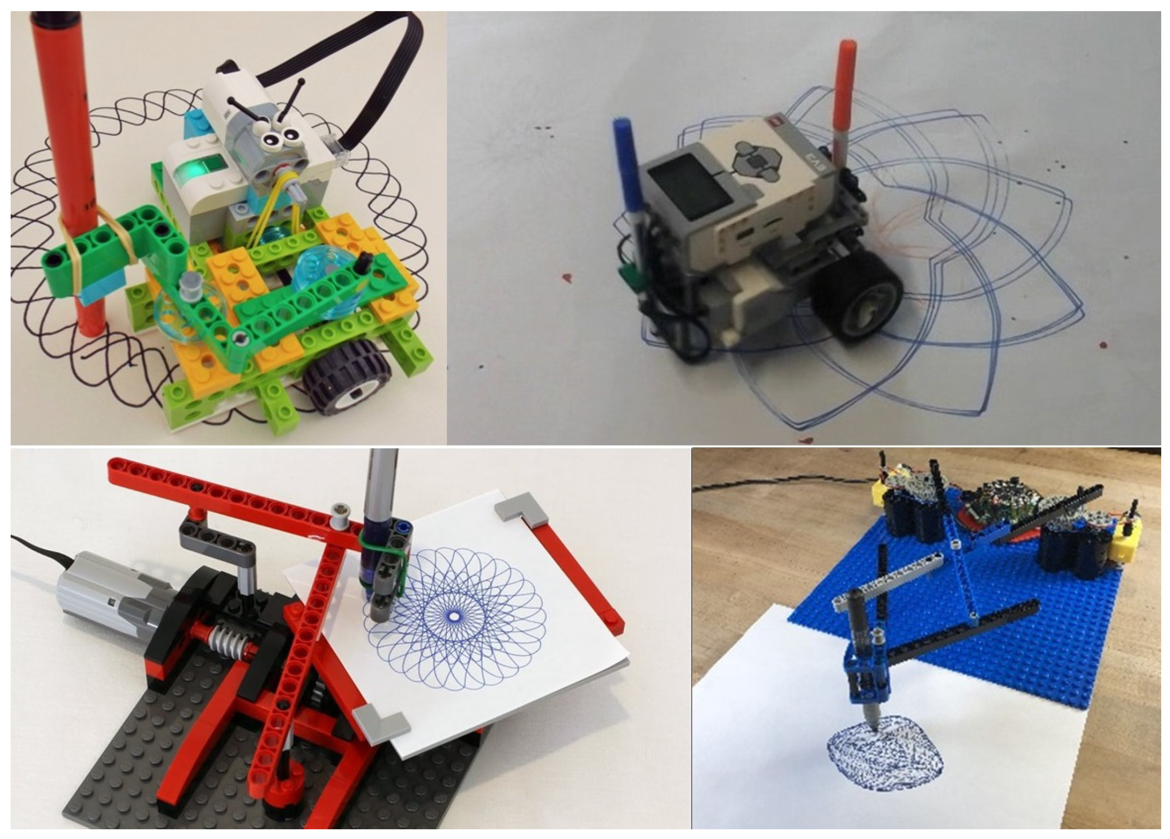
Figure 2.
Generating a curtate epitrochoid (left) and a prolate hypotrochoid (right).
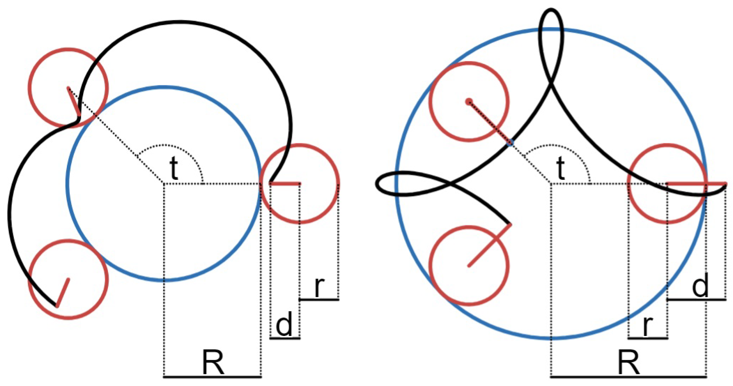
Figure 3.
Final model picture of the the Spirograph-like drawing robot.
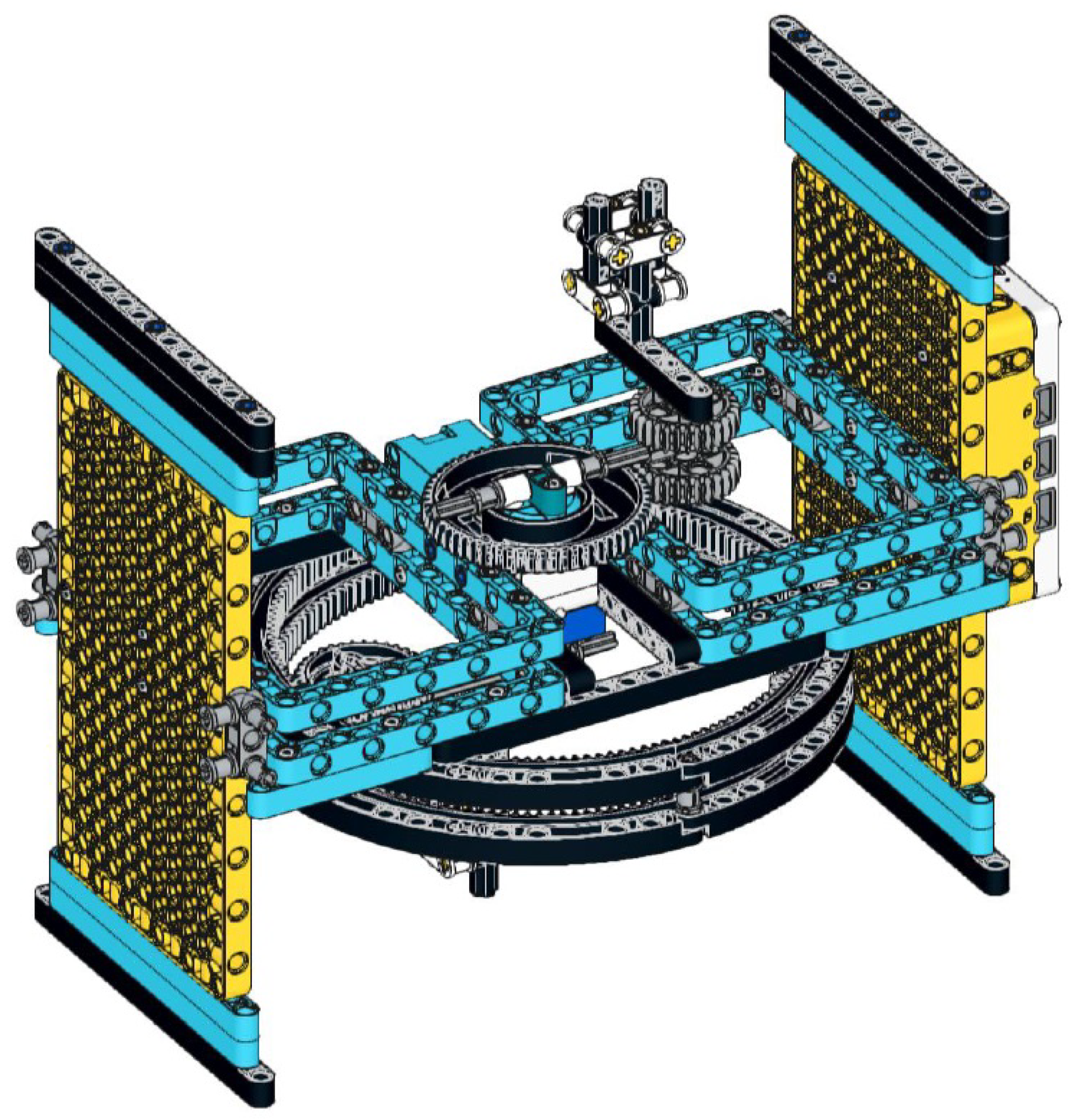
Figure 4.
Final model picture of the SCARA-type drawing robot.
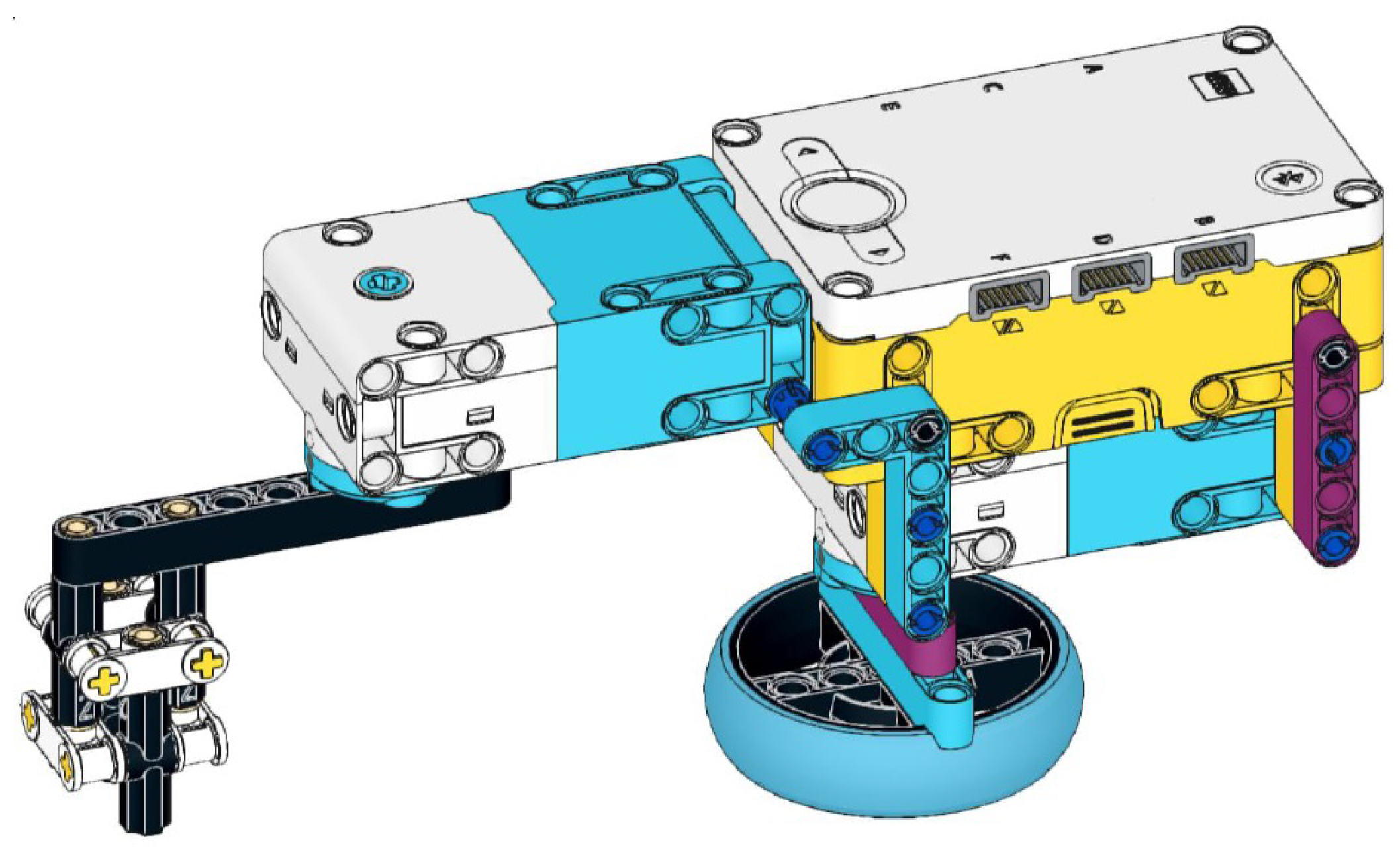
Figure 5.
Verification and validation stages of the V-model [36].
Figure 5.
Verification and validation stages of the V-model [36].
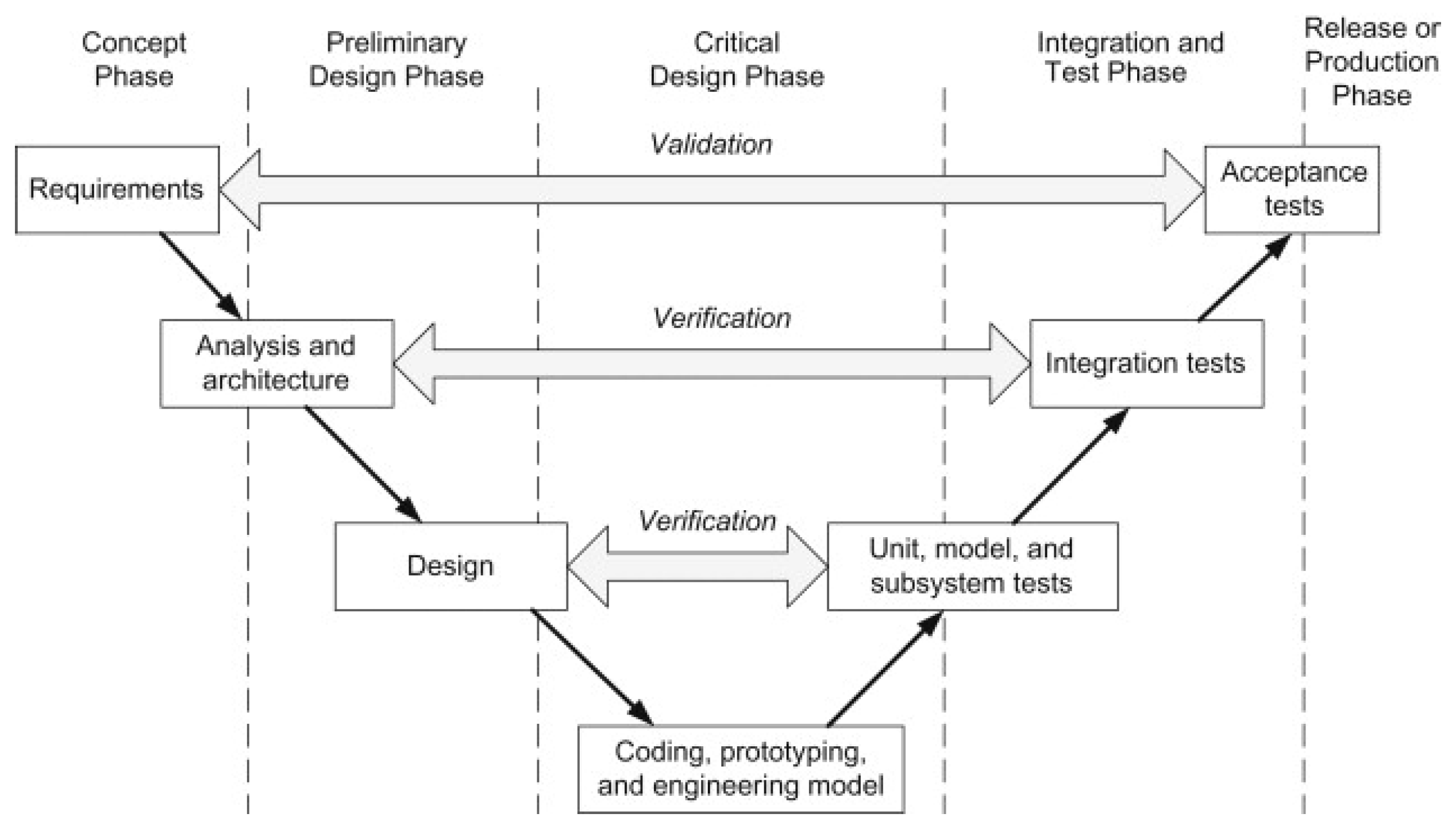
Figure 6.
The new robot and its main parts.
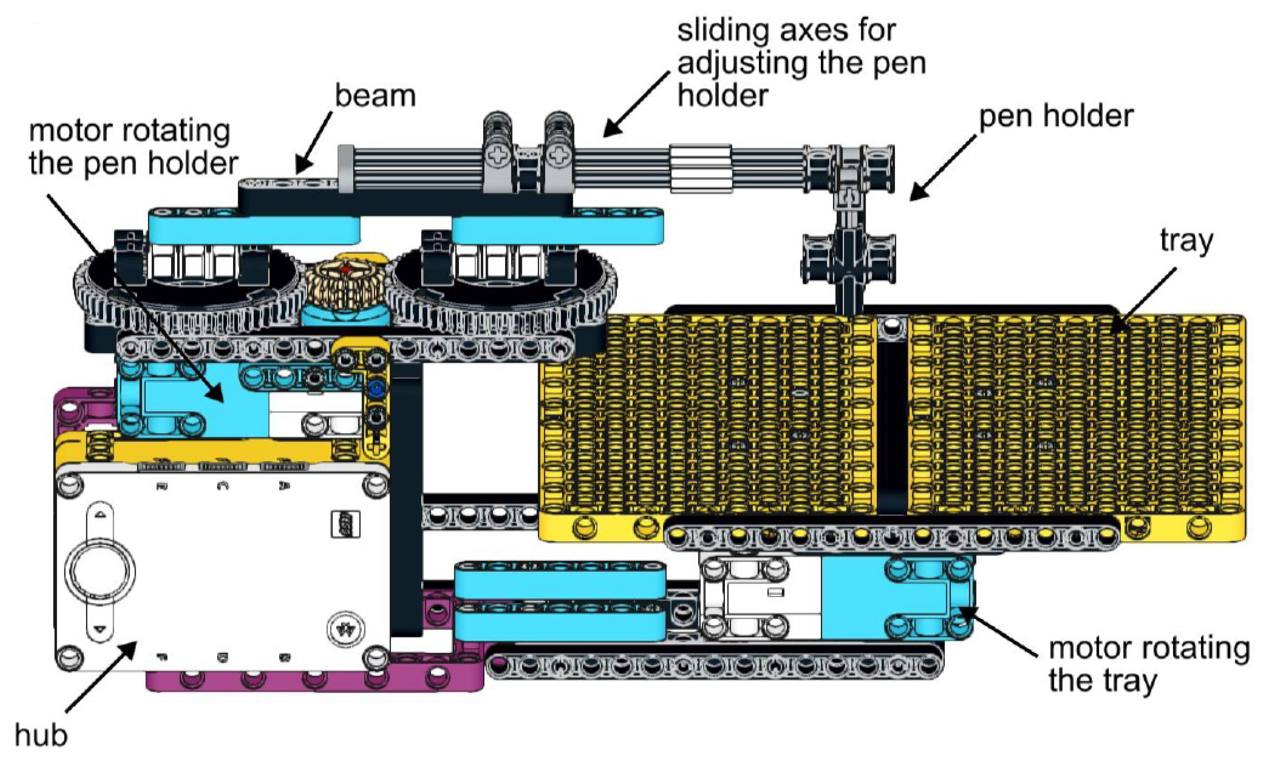
Figure 7.
Typical code for drawing a central trochoid.
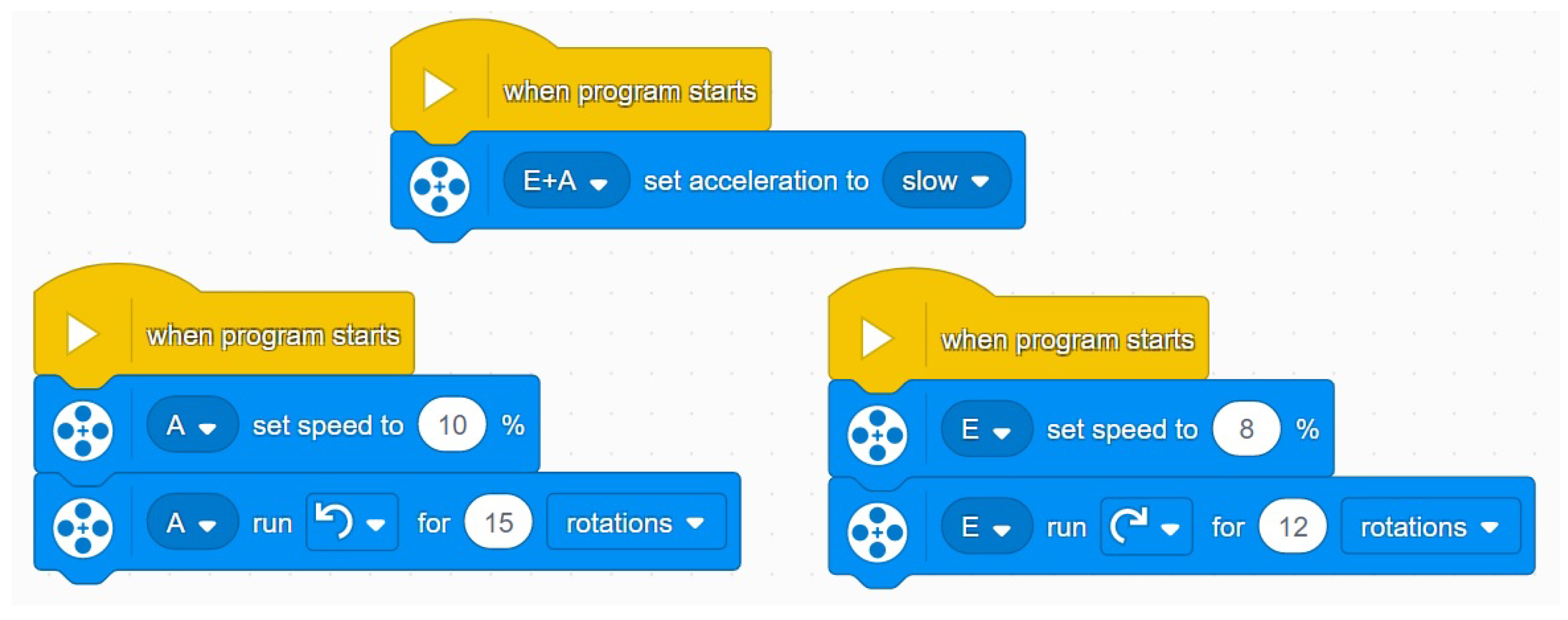
Figure 8.
Central trochoids drawn by the robot with parameters , and .
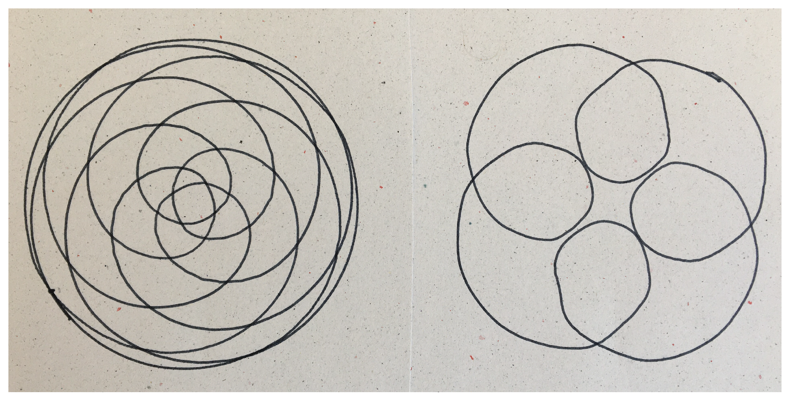
Figure 9.
Snapshot of the Desmos dynamic geometry software.
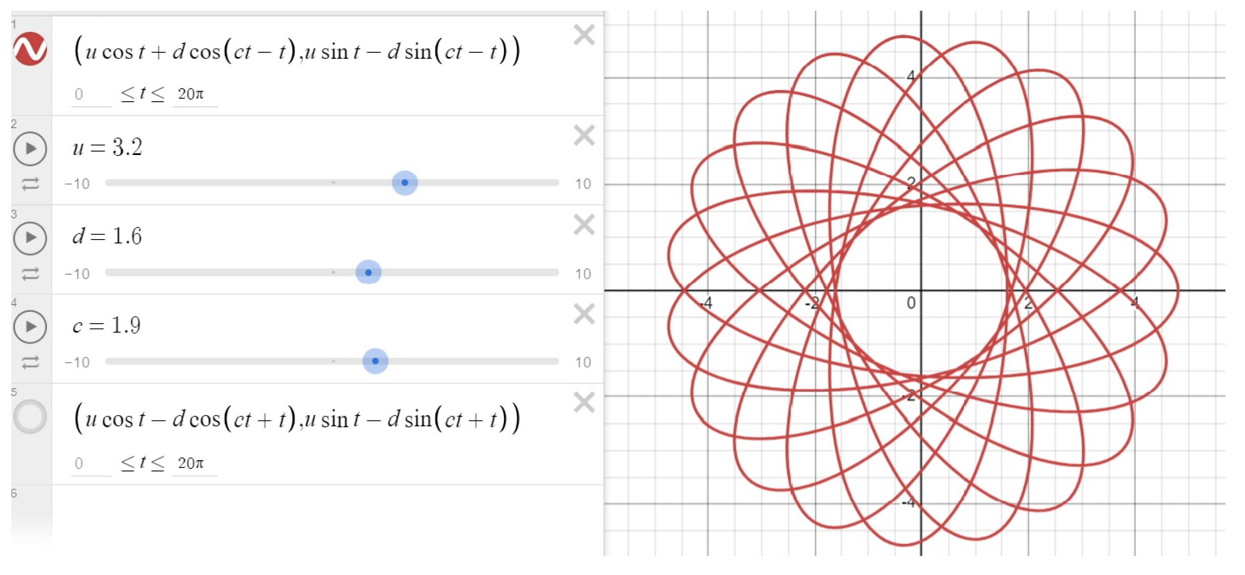
Figure 10.
Central trochoids produced by Desmos with settings , and .
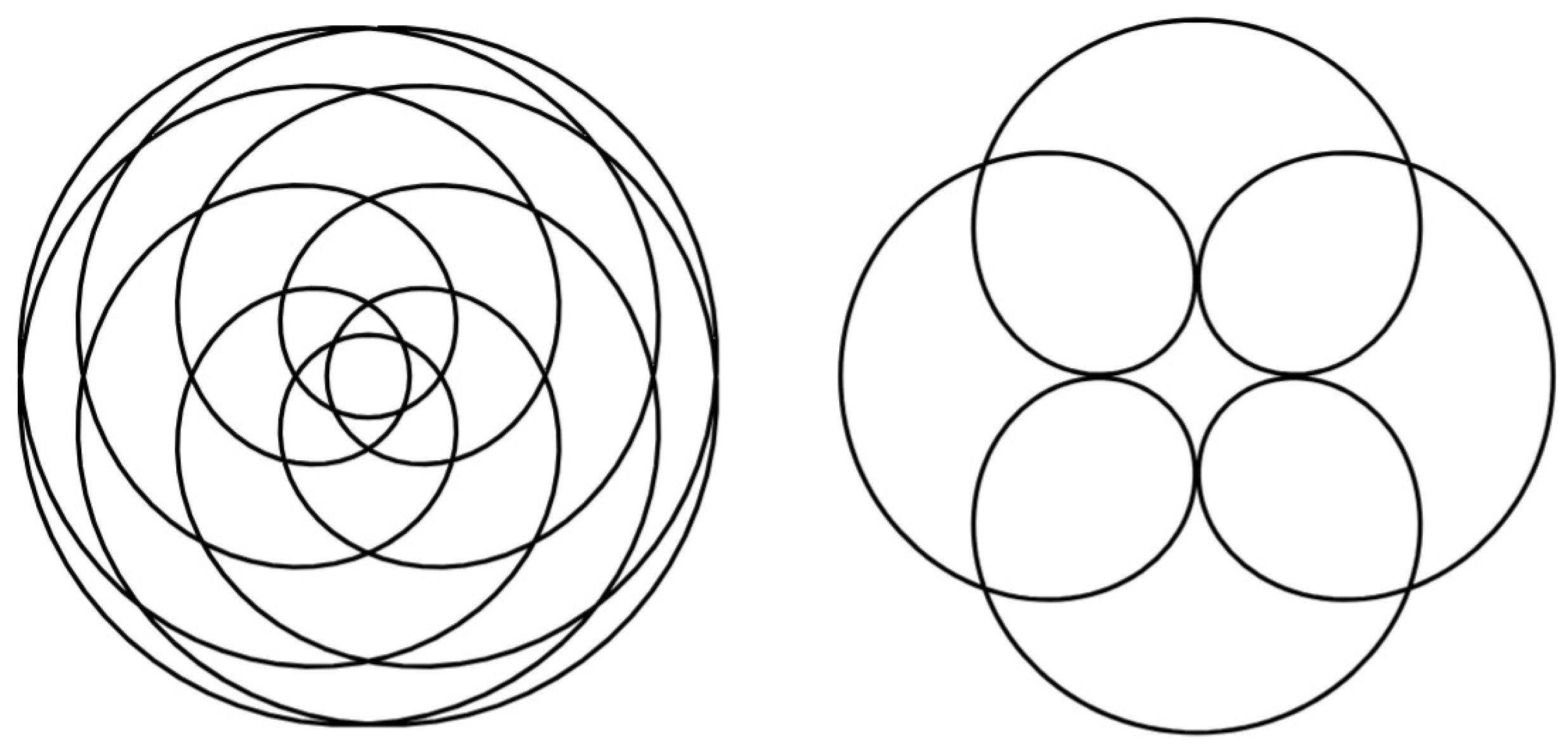
Figure 12.
Categorized central trochoid drawings (created by students).
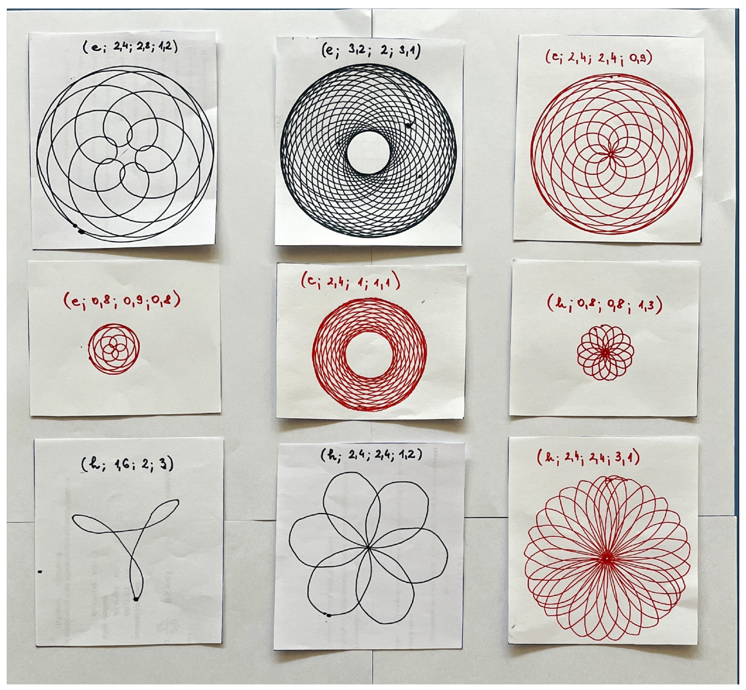

Table 1.
Curves as special central trochoids.
| Epitrochoids | Hypotrochoids |
|---|---|
| circle | circle |
| limaçon | ellipse |
| cardioid | astroid |
| nephroid | rhodonea |
Table 2.
Parameter transformation in central trochoid equations.
| Parameter | Epitrochoids | Hypotrochoids |
|---|---|---|
| u | ||
| c | ||
| r | ||
| R |
Disclaimer/Publisher’s Note: The statements, opinions and data contained in all publications are solely those of the individual author(s) and contributor(s) and not of MDPI and/or the editor(s). MDPI and/or the editor(s) disclaim responsibility for any injury to people or property resulting from any ideas, methods, instructions or products referred to in the content. |
© 2024 by the authors. Licensee MDPI, Basel, Switzerland. This article is an open access article distributed under the terms and conditions of the Creative Commons Attribution (CC BY) license (http://creativecommons.org/licenses/by/4.0/).
Copyright: This open access article is published under a Creative Commons CC BY 4.0 license, which permit the free download, distribution, and reuse, provided that the author and preprint are cited in any reuse.


