Submitted:
04 September 2024
Posted:
09 September 2024
You are already at the latest version
Abstract
The small dimensions of microfluidic channels allow for fast diffusive or passive mixing, which is beneficial for time-sensitive applications such as chemical reactions, biological assays, and the transport of to-be-detected species to sensors. In microfluidics, the need for fast mixing within milliseconds arises primarily because these devices are often used in fields where rapid and efficient mixing significantly impacts the performance and outcome of the processes. Active mixing with acoustics in microfluidic devices involves using acoustic waves to enhance the mixing of fluids within microchannels. Using sharp corners and wall patterns in acoustofluidic devices significantly enhances mixing by acoustic streaming around these features. The streaming patterns around sharp edges are particularly effective for mixing because they can produce strong lateral flows that rapidly homogenize liquids. This work presents extensive characterizations of the effect of sharp-edged structures on acoustic mixing in bulk acoustic wave (BAW) mode in a silicon microdevice. The effect of side wall patterns in different angles and shapes, their position, the type of piezoelectric transducer, and its amplitude and frequency have been studied. Following the patterning of the channel walls, a mixing time of 25 times faster was reached, compared to channels with smooth sidewalls exhibiting conventional BAW behavior. The average locally determined acoustic streaming velocity inside the channel becomes 14 times faster if sharp corners of 10° are added to the wall.
Keywords:
sharp corners
; fast mixing
; acoustofluidics
1. Introduction
Microfluidic systems are primarily interesting because they can handle small volumes of fluids with high precision and efficiency, which is crucial in various scientific and industrial applications. Microfluidic devices allow for precise control over fluid dynamics because of the small volumes in the order of microliters, and liquid manipulation can be faster than in macro-scale systems. This control is essential for applications where precise mixing ratios and patterns are necessary, such as biomedical research, pharmaceutical analysis, and chemical reaction engineering. For a range of applications, handling expensive or hazardous chemicals in small volumes can significantly reduce costs and waste, in addition to enhancing safety during testing [1].
The small dimensions of microfluidic channels facilitate rapid mixing, which is beneficial for time-sensitive applications such as chemical reactions and biological assays. The reduced scale of microfluidic devices enhances diffusion, a primary mechanism by which mixing occurs at such small scales. This is critical for achieving homogeneous mixtures in a short time frame. Microfluidic devices can be integrated into larger systems and allowed to perform multiple functions on a single chip, often called "lab-on-a-chip" devices. This integration can include various processing stages, such as mixing, reaction, separation, and detection, all within a compact and scalable platform [2]. Microfluidics offers innovative passive and active mixing techniques that are not feasible in larger systems. Passive mixers use dedicated channel geometries that enhance mixing by generating advection without external energy input. In contrast, active mixers employ external forces such as magnetic fields, acoustic waves, or electric fields to improve mixing principally by convection [1].
Each of these methods has its own set of advantages and limitations. Passive mixers are generally more straightforward and cheaper to fabricate and operate since they do not require external energy inputs after the initial fluid propulsion. However, they might offer a different mixing efficiency or control level than active mixers. Active mixers, while potentially more complex and costly to implement, can provide faster and more controllable mixing, which is crucial for applications requiring rapid and homogeneous mixing of reactants [3].
Active mixing with acoustics in microfluidic devices involves using acoustic waves to enhance the mixing of fluids within microchannels. This method is particularly effective in overcoming the challenges posed by the laminar flow conditions that are typical in microfluidics, where low Reynolds numbers prevent turbulent mixing [4]. Acoustic mixing utilizes the energy exchange between acoustic waves and the fluid medium to achieve spatial and temporal manipulation of matter. This can involve different types of acoustic waves, such as surface acoustic waves (SAWs) and bulk acoustic waves (BAWs), which interact with the fluids to induce mixing through mechanisms like acoustic streaming and the generation of pressure nodes and antinodes [5].
Surface acoustic waves (SAWs) are acoustic waves that travel along the surface of an elastic material. The most common method for generating SAWs involves the use of interdigitated transducers (IDTs) patterned on the surface of piezoelectric substrates. When an electrical signal is applied to these IDTs, the piezoelectric effect causes mechanical deformation of the substrate, generating acoustic waves that propagate along the surface. This process transforms applied electrical energy into mechanical energy, effectively generating SAWs. The specific patterns and dimensions of the IDTs, a result of adaptable design, can be adjusted to control the frequency and characteristics of the generated waves [6].
Bulk Acoustic Waves (BAWs) are acoustic waves propagating through the bulk of a material rather than along its surface. These waves can be categorized into different types based on their propagation mode. The first type is longitudinal waves inside the medium in the same or opposite direction of particle oscillation. These waves are also called pressure waves (mechanical waves) because they involve compressions and rarefactions of the material they travel through. The other type is transverse waves, which propagate through the medium perpendicular to the direction of particle oscillation. They are also known as shear-mode waves because they involve the shearing of the material [7].
BAWs are generated primarily through piezoelectric transducers. These devices most often use piezoelectric materials, which have the property of generating an electrical charge when mechanically stressed and vice versa. When an alternating voltage is applied to a piezoelectric crystal, it induces mechanical vibrations at the same frequency as the applied voltage. These vibrations propagate as acoustic waves through the bulk of the material [8].
In microfluidics, the need for fast mixing within milliseconds arises primarily because these devices are often used in fields such as chemical analysis, biological assays, medical diagnostics, and drug development, where rapid and efficient mixing of reagents can significantly impact the performance and outcome of the processes involved. Many chemical and biological reactions require rapid and homogeneous mixing of reactants to proceed efficiently. Fast mixing ensures that reactants are quickly and evenly distributed, significantly enhancing reaction kinetics and leading to faster reaction times and improved yields. Also, in diagnostics and analytical chemistry, by rapidly changing the concentration of reactants or other reaction parameters, researchers can investigate the time-dependent behavior of systems with high resolution [1].
The use of sharp corners and wall patterns in acoustofluidic devices significantly enhances mixing by leveraging the phenomenon of acoustic streaming around these geometric features. The initial interest in sharp corners within acoustofluidic contexts likely stemmed from observations of acoustic streaming and acoustic radiation force phenomena, which are fundamental to manipulating fluids and particles at the microscale [9]. These phenomena are significantly influenced by the geometry of the microfluidic device, with sharp corners and edges producing strong localized acoustic fields [10].
The streaming patterns around sharp edges are particularly effective for mixing because they can produce strong vortices and flow circulations that rapidly homogenize the fluids [11]. Combining sharp-edge geometries and acoustic excitation facilitates more efficient mixing in acoustofluidic devices. Mixing performance can be significantly enhanced by carefully designing the device geometry to include sharp corners and specific wall patterns and optimizing the acoustic excitation parameters [12].
In this work, we conduct extensive characterizations of the effect of sharp-edged structures on acoustic mixing in BAW mode in a silicon microdevice. In past studies, researchers have worked on the effect of sharp corners made in polydimethylsiloxane (PDMS) substrates in SAW acoustic mode. They demonstrated a decrease in flow velocity by increasing the sharp edge angles placed in the channels, achieving a mixing index of 40-60% [13,14,15]. Our work is among the very few studies [16] characterizing these structures and the effect of their tip angle on the streaming velocity in crystalline silicon-made devices in BAW mode. The effect of side wall patterns in different angles and shapes, their position, the piezoelectric transducer used, and tuning with amplitude changes has been studied. This research gives insight into the adaptations to improve mixing efficiency and reduce processing times. The silicon-glass composition of devices used in this work also addressed challenges related to chemical resistance and long-term use, further expanding potential applications of sharp-edge acoustofluidics.
2. Materials and Methods
2.1. Acoustofluidic Setup
The microfluidic chip consisted of a micro-channel (20 mm×375 µm×525 µm) in silicon. The channel was etched with Deep Reactive Ion Etching (DRIE) all the way through the silicon wafer thickness and was sealed with two MEMpax® borosilicate glass wafers from both sides by anodic wafer bonding. The microchip was placed on top of a ceramic piezo element (20 mm×15 mm×1 mm, APC International Ltd., USA) with a thin layer of glycerol in between as a coupling agent. The piezo element generated a 2.2 MHz resonance frequency by a frequency generator (AFG1062, Tektronix UK Ltd., UK), and the applied voltage was amplified 340 times by an RF power amplifier (210L, Acquitek S.A.S, France) with a power output of 10 Watt. The setup parts were fixed together with the help of two PMMA holder pieces. Figure 1 depicts the complete overview of the microchip and the assembly of the acoustofluidic setup.
2.2. Determination of Average Velocity Magnitude of Acoustic Streaming
Fluorescent monodisperse polystyrene particles of 1 µm in size (Microparticles GmbH, Germany), diluted to 0.005 w/v% in water, were pumped into the channel, the flow stopped, and movies were recorded while applying acoustic force to the chip. A set of movies was made was made using an inverted light microscope (Leica DMi8, Leica, Wetzlar, Germany) enhanced with a CCD fluorescent camera (C13440-20C, Hamamatsu Photonics, Hamamatsu City, Japan), and a potential of 3–31 V was applied. The velocity of suspended particles as a function of their position in the channel was studied and processed with a customized MATLAB code. The code was used to calculate the velocities by dividing the distances between consecutive positions by the time step.
2.3. Mixing Efficiency (Index) Experiments
Two samples with filtered DI water were prepared for mixing index experiments: one containing a florescent dye (fluorescein sodium salt, Sigma-Aldrich, Germany) and the other without dye. With constant pressure, the dyed water was pumped from the inlets on the two sides into the channel, and the undyed water was pumped from the middle inlet. These two samples were mixed at a 2.2 MHz resonance frequency, and a potential of 170 V was applied. As the fluorescence intensity is proportional to the dye concentration, the intensity value can be used to indicate concentration [17]. The intensity information from the images was subsequently extracted in a region under the influence of acoustic streaming. The mixing indexes were extracted in a region under the influence of acoustic streaming from the pixels intensities across a grayscale image cross-section delineating a mixing event, and they were calculated by determining the standard deviation of the pixel intensities in the cross-section with a customized MATLAB code. The relative mixing index was calculated by considering the following formula, which deducts the ratio from 1 in percentage form [18]. The given formula is a specific expression for the mixing index, η, which compares the current state of mixing to the initial and fully mixed states. This formula is useful for quantifying the degree of mixing more precisely:
η: Mixing index, with values ranging from 0 (no mixing) to 1 (perfect mixing).
n: Number of measurement points.
Normalized intensity at the i-th measurement point in the current state.
: Normalized intensity at the i-th measurement point in the fully mixed state.
: Normalized intensity at the i-th measurement point in the initial (unmixed) state.
3. Results and Discussion
A silicon microdevice with recurring sharp corners on the channel side wall of 30º was made to evaluate whether this structure has benefits over a regular straight channel. All the devices in this study were etched in silicon substrates and were made by a Bosch process from the Deep Reactive Dry Etching (DRIE) category. Figure 2 shows a SEM image of the device; as is evident from the images, the sharp edges turned out to be of different sizes and different continual consistency. In DRIE, high aspect ratios (AR, depth to width ratio) and smaller feature sizes increase the difficulty of maintaining sharp profiles. The etching uniformity control decreases as the AR increases, leading to more pronounced scalloping and less sharp features [19]. On the other hand, the isotropic etching phase of the Bosch process is characterized by less directional ion bombardment, which does not discriminate between horizontal and vertical surfaces. This non-selectivity can lead to lateral etching under the mask, resulting in rounded or sloped profiles rather than sharp, defined edges [20].
The channel width of these microchips was chosen based on the standing wave criterion of BAWs. This means that at 2 MHz resonance frequency (PZT thickness:1 mm), in water, the sound velocity equals 1.5×10³ m/s, corresponding to a wavelength of 750 µm. Based on this indication, at 2 MHz resonance frequency, one pressure node forms in the 375 µm channel. However, when introducing the sharp corners to the channel, determining which PZT transducer and frequency were optimal for this microdevice is not straightforward. Therefore, to choose which PZT transducer and resonance frequency to use, four PZT transducers with different thicknesses from 0.91-1.25 mm were used to measure the average streaming (lateral flow) velocity at an applied frequency range between 1.6-2.6 MHz at 34 V. The results are shown in Figure 3.
The results show that the best-performing PZT transducers are the 1.1 mm at 2 MHz and 1 mm at 2.2 MHz. The characterization experiments continued with the 1mm PZT transducer at 2.2 MHz frequency because of the wide availability of this PZT type in our lab.
The mixing efficiency of the microdevice with recurring 30º sharp corners was measured at 2.2 MHz with an amplitude of 170 V. The top experimental image shows the flow of water and fluorescent dye when the acoustic device is turned off, and the bottom experimental image shows the mixed fluorescent dye when the acoustic device has been turned on. The graph next to it shows the mixing index (efficiency) versus the time when the acoustic is turned on and off two consecutive times.
The results show the mixing index reaches almost 80 % within 0.2 s. The mixing rate was dramatically improved when comparing the results with those without structures on the side wall. The mixing efficiency takes around 5 s to reach 65% in the same conditions for a regular channel. Therefore, the mixing time was reduced a a factor of 25. Sharp corners or edges in microfluidic channels can intensify mixing by creating localized flow disturbances, leading to micro vortices and streaming flows. These flows enhance mixing of fluids by disrupting the typical laminar flow patterns common in microscale environments. The interaction of acoustic waves with sharp edges leads to a steady flow known as sharp-edge acoustic streaming (SEAS). This streaming can significantly enhance mixing by continuously stirring the fluids, thus reducing the mixing length and time required to achieve homogeneity [21]. The geometry of the sharp edges, including the angle and spacing between edges, plays a crucial role in the effectiveness of mixing. Optimal sharp-edge designs can maximize the streaming velocity and the extent of the induced vortices, thereby improving the mixing efficiency [22]. Studies have shown that the sharp-edge structures can be optimized for more effective mixing patterns. For instance, specific configurations of sharp edges where the spacing between each tip is 200-300 µm allow fluids to jump out from each sharp edge to reach zones between two consecutive edges at the opposite wall, enhancing the mixing process. Direct numerical simulations and experiments with dye visualizations have confirmed that SEAS micromixers can decrease the micromixing time significantly by optimizing the sharp-edge patterns and operating conditions [22].
The influence of the sharp corner position on mixing has also been investigated, showing that the placement and design of these corners can be crucial for achieving efficient mixing in microfluidic devices [13].
When comparing the velocity vector sizes shown in the two images next to one another in Figure 5, it is clear that acoustic streaming of sharp-edged structures increases by increasing the voltage applied to piezoelectric transducers that generate acoustic waves. Higher amplitudes lead to increased acoustic streaming flows around sharp edges, evident by the size of velocity vectors in the figure, which is crucial for enhancing mixing in silicon devices. The increase in streaming velocity with higher voltages is due to the more significant energy input into the system, which improves the amplitude of acoustic vibrations. These stronger vibrations lead to more pronounced acoustic streaming effects, particularly around sharp edges where the flow disturbances are maximized due to the geometric singularities. It is well known that increasing the voltage from 10V to 40V significantly improves micromixing by reducing the mixing time [22].
Although the device with 30º sharp structures showed promising results, the optimal ideal tip angle for fast mixing purposes must be evaluated in more detail. To this end, the average velocity of the streaming around sharp corners of 10º, 20º, 30º, 40º, and 60º was measured at 2.2 MHz between 9-28 Vpp. The results in Figure 6 indicate that the best-performing tip angle for achieving fast mixing is firstly 10º and secondly 20º. These two angles can increase the streaming velocity 14 and 8 times, respectively, compared to a channel with the same width and depth lacking sharp corners (Refer to SI video S3). Beyond these two angles, the average velocity decreased drastically. Still, the average velocity beyond 20º and until 60º is 1.5 times faster than in the same conditions and channel only without the sharp-edged structures. In a study on PDMS-based microdevices, four different tip angles of 15°, 30°, 45°, and 60° were investigated to determine the optimal angle for the best acoustic streaming effect and mixing performance. The results demonstrated that rapid and homogeneous mixing could be achieved by optimizing the design of the sharp edges. 15º showed fast, excellent mixing, while 30º mixing results and mixing time were acceptable [12]. Figure 6 shows the tip angle's effectivity and the positive trend of increasing the amplitude, resulting in higher streaming velocity. Due to the abrupt change in flow direction, a sharper edge induces stronger and more localized vortices. These vortices promote chaotic advection, where fluid particles mix rapidly across different streamlines. A less sharp edge still induces vortices but to a lesser extent. The smoother change in flow direction reduces the intensity and effectiveness of vortex formation, leading to less efficient mixing. Also, higher shear stress is generated with sharper tips, which enhances fluid dispersion and accelerates the mixing process. With fewer sharp corners, shear stress is lower, resulting in slower fluid dispersion and potentially leaving unmixed regions within the channel. This can lead to incomplete mixing and longer mixing times.
Other than the tip angle, another variable is the tip shape; adding more corners or edges over the tip produces extra micro-streaming lesions, increasing the streaming velocity and speeding up mixing. Four different tip shapes were produced, and 1 µm polystyrene particles were introduced into the channel. Multiple images were captured at different focal depths (z-planes), and then they were combined to produce a single image that is sharp and in focus throughout the entire depth. This so-called z-stacking of the experimental movie frames at the max intensity combined with each other shows that each tip shape reveals flow characteristics. Both the sketched design of the tip shape and an image of the produced tip shape in silicon taken with an optical microscope are included in Figure 7.
This variation in shape and the displacement micro-streaming results in different average streaming velocities at the same amplitude. As shown in Figure 7, some shapes have inactive areas around where no displacement is observed, which can cause those shapes not to be suited for fast mixing applications. To conclude which tip shape works best, the tip shapes were organized in Figure 8 based on their streaming average velocity magnitude. Also, the effect of the sharp-edged structure was studied in two different areas. The blue bars are the measured average velocity in a 2.5 times bigger area than the green bars.
Figure 8 clearly shows the tips with more edges present the best performance. However, if we follow the displacement lines around the sharp tip in Figure 7, the best performance was obtained for the tip shapes with more symmetrical displacement with no inactive area (Figure 8. b and d). With these findings, it can be concluded that next to the tip angle of the sharp edges and the ratio h/H between the distance of the sharp edges from the wall (h) and the overall channels width (H) [19], the shape of the tip affects the flow field as well.
The position of the sharp edges has been studied before in PDMS devices. When the sharp corners are positioned closer to one another than 100 µm, the mixing performance deteriorates [17]. Also, with precise calculation and simulations, a silicon device was made containing two side wall sharp edges that mix, pump, and trap the particles [11]. In this work, we tested the position of the sharp structures in the middle of the channel as a 3D structure. When the acoustic force is applied, SEAS occurs. Interestingly, after a few seconds, a unidirectional pumping effect occurs inside the channel, and the liquid inside starts pumping in one direction to the point that, within seconds, the channel is almost emptied (Please refer to the SI video S4).
Figure 9.
Z-stacking of particle movements in the channel with triangular pillars. The top-left image shows all the frames since the start of streaming and pumping on top of one another.
Figure 9.
Z-stacking of particle movements in the channel with triangular pillars. The top-left image shows all the frames since the start of streaming and pumping on top of one another.
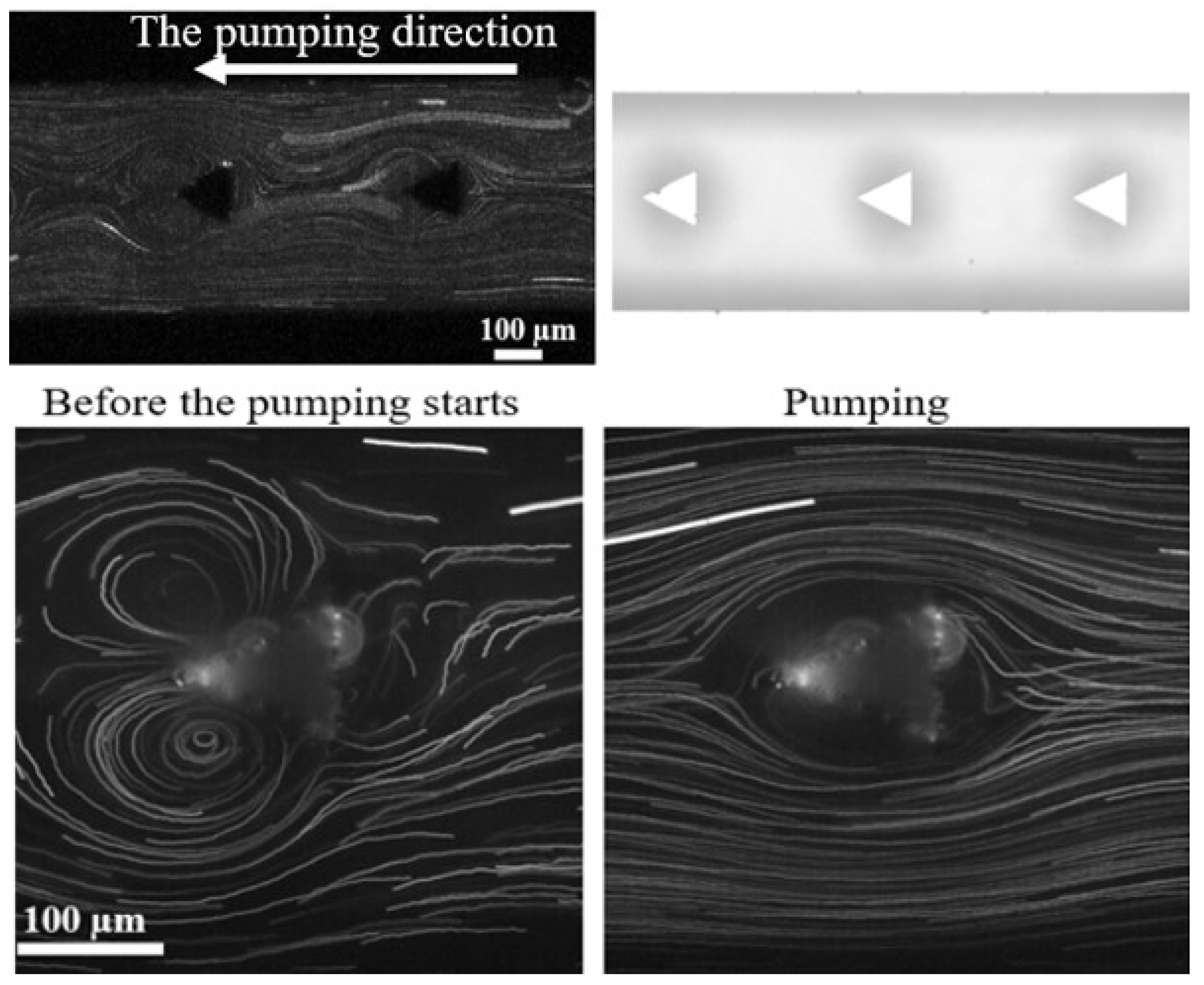
This result shows that by placing the sharp corners inside the channel, we create an abrupt change in the channel flow direction. Streaming around the sharp edges, its vortices, and circulations in the middle of the channel result in a net force directed to one side of the channel, and pumping occurs because the generated net forces by acoustic streaming push the bulk fluid forward. This effect can be tuned by changing the applied voltage; the higher the voltage, the less time it takes for the pumping to start following the sharp edge streaming (SI S4 and S5). Both the effect of directionality and the applied voltage on the pumping effect were done before with structures pointing in one direction at the edge of the rectangular channels in PDMS [14], which seems to be a similar effect to what is observed in our silicon devices with sharp-edged pillars placed in the middle of the channel. Another variation of the pumping device was made but with circular 3D structures in the middle of the channel. Surprisingly, the circular and sharp-edged pillars showed the streaming around the pillars and the pumping effect (Please refer to SI video S5). However, the time needed for pumping to start was longer for circular structures compared to triangular structures at the same amplitude. This phenomenon can be explained by the fact that the sharp corner can be parallel to the transducer position (like the triangular pillar), or the sharp corner can be orthogonal to the transducer position (the circular pillar with the scallops originating from the DRIE process), which means the circular pillar also contains sharp angles like the triangular pillar but in a different position and based on their angle the vortices forms in different patterns [23]. In our study, the channels were sealed with a glass wafer, and the scallop formation can induce the circulation and movement of liquid around the circular pillars (Figure 10b).
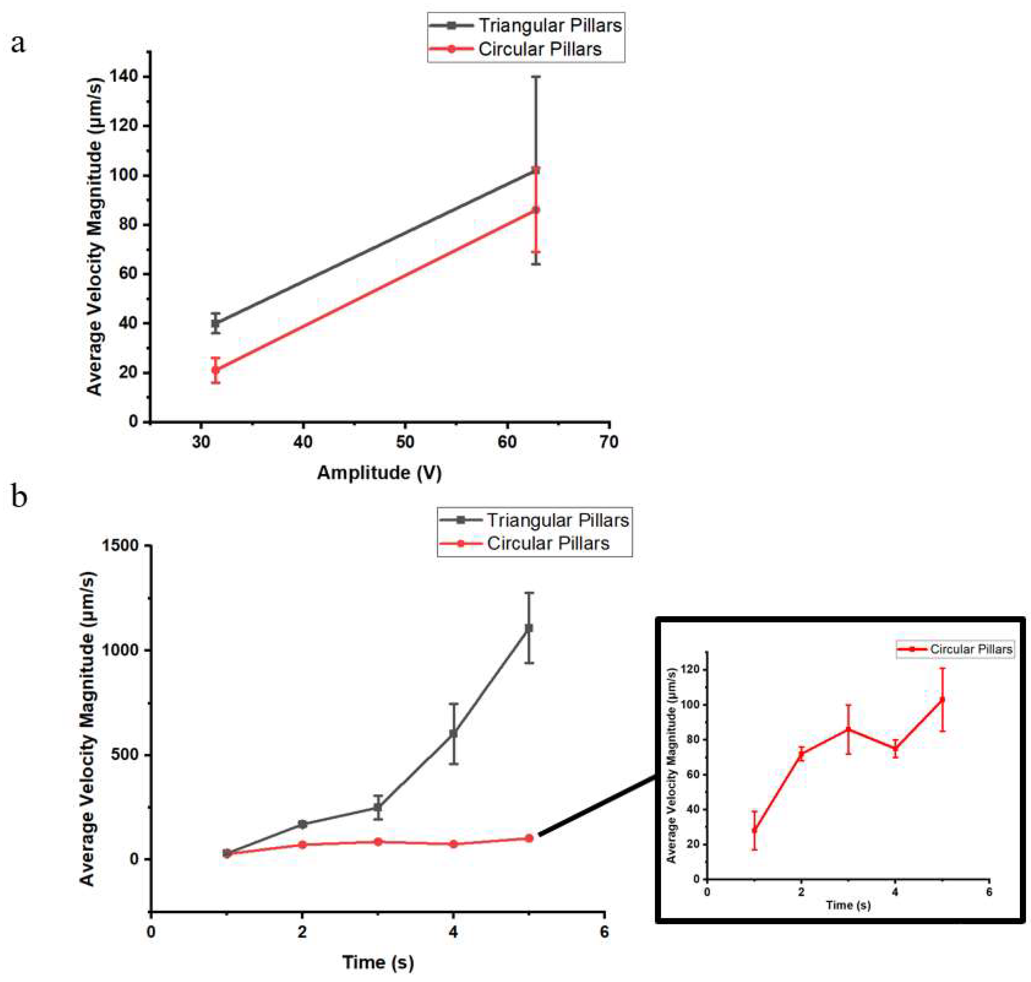
Before the pumping effect starts, there are liquid movements around the pillars. The movement patterns in a channel with triangular pillars are similar to the symmetrical streaming happening around the sharp edge (Figure 9), and the movement around the circular pillar is rotated in one direction around each pillar (Figure 10). When the average velocity of such movements is compared with each other, Figure 11.a shows that both movements in the channel become faster by increasing the applied voltage and that the flow patterns around the triangular pillar are faster than those around circular pillars. When the pumping effect starts, the pumping velocity increases with time (Figure 11.b). This increase is more significant in channels with triangular pillars yet still discoverable in channels with circular pillars. The leading cause of the pumping effect is yet to be characterized and studied in more depth in a follow-up publication.
4. Conclusion
In this work, we have conducted extensive characterizations of the effect of sharp-edged structures on acoustic mixing in BAW mode in a silicon microdevice. The side wall patterns with 10º and 20º tip angles show the best mixing performance in terms of mixing time. The tip shapes also influence the number of vortices formed, as well as their position and their performance. Also, the best resonance frequency used for four different piezoelectric transducers was determined for the studied microdevice. The tuning ability of these structures with amplitude changes has been demonstrated. The placement of 3D structures in the middle of the channel showed a non-mechanical pumping effect that is tuneable with an applied voltage that can be valuable in many aspects of the lab-on-a-chip industry. This research gives insight into the adaptations to improve mixing efficiency and reduce processing times; the silicon-glass composition of devices used in this work solves challenges related to chemical resistance and long-term use, expanding the potential applications of sharp-edge acoustofluidics in biomedical and sensing applications.
Author Contributions
Conceptualization, W.D.M. and P.G.; methodology, M.H., P.G, and W.D.M.; device design, M.H, and P.G.; device fabrication, M.H.; data curation, M.H., and P.G; writing and original draft preparation, M.H.; review and editing, W.D.M., and H.G.; visualization, M.H., and P.G; supervision, W.D.M., and H.G.; project administration, W.D.M.; funding acquisition, W.D.M. All authors have read and agreed to the published version of the manuscript.
Funding
This research was funded by a Strategic Research Program on Microfluidics (SRP51) at Vrije Universiteit Brussel.
References
- Ward, Z.H. ; Kevin; Fan, “Mixing in microfluidic devices and enhancement methods Manuscript version : Accepted Manuscript Manuscript version : Accepted Manuscript. Top. Rev 2015, 25, 1–33. [Google Scholar] [CrossRef]
- Lee, C.Y.; Chang, C.L.; Wang, Y.N.; Fu, L.M. Microfluidic mixing: A review. Int. J. Mol. Sci 2011, 12, 3263–3287. [Google Scholar] [CrossRef] [PubMed]
- Li, Z.; Zhang, B.; Dang, D.; Yang, X.; Yang, W.; Liang, W. A review of microfluidic-based mixing methods. Sensors Actuators A Phys. 2022, 344, 113757. [Google Scholar] [CrossRef]
- Westerhausen, C.; et al. Controllable acoustic mixing of fluidsc in microchannels for the fabrication of therapeutic nanoparticles. Micromachines 2016, 7, 1–18. [Google Scholar] [CrossRef]
- Liu, M.; et al. An IoT-enabled paper sensor platform for real-time analysis of isothermal nucleic acid amplification tests. Biosens. Bioelectron. 2020, 169, 112651. [Google Scholar] [CrossRef] [PubMed]
- Mandal, D.; Banerjee, S. Surface AcousticWave (SAW) Sensors: Physics, Materials, and Applications. Sensors 2022, 22. [Google Scholar] [CrossRef]
- Wang, L.; et al. A Review on Coupled Bulk Acoustic Wave MEMS Resonators. Sensors 2022, 22, 1–32. [Google Scholar] [CrossRef]
- Yang, Y.; Dejous, C.; Hallil, H. Trends and Applications of Surface and Bulk Acoustic wave Devices: A review. Micromachines 2022, 14, 43. [Google Scholar] [CrossRef] [PubMed]
- Rasouli, M.R.; Tabrizian, M. An ultra-rapid acoustic micromixer for synthesis of organic nanoparticles. Lab on a Chip 2019, 19, 3316–3325. [Google Scholar] [CrossRef]
- Bachman, H.; et al. An acoustofluidic device for efficient mixing over a wide range of flow rates. Lab Chip 2020, 20, 1238–1248. [Google Scholar] [CrossRef]
- Pavlic, A.; Harshbarger, C.L.; Rosenthaler, L.; Snedeker, J.G.; Dual, J. Sharp-edge-based acoustofluidic chip capable of programmable pumping, mixing, cell focusing, and trapping. Phys. Fluids 2023, 35. [Google Scholar] [CrossRef]
- Huang, P.H.; et al. An acoustofluidic micromixer based on oscillating sidewall sharp-edges. Lab Chip 2013, 13, 3847–3852. [Google Scholar] [CrossRef]
- Nama, N.; Huang, P.-H.; Huang, T.J.; Costanzo, F. Investigation of acoustic streaming patterns around oscillating sharp edges. Lab on a Chip 2014, 14, 2824–2836. [Google Scholar] [CrossRef] [PubMed]
- Huang, P.-H.; et al. A reliable and programmable acoustofluidic pump powered by oscillating sharp-edge structures. Lab on a Chip 2014, 14, 4319–4323. [Google Scholar] [CrossRef]
- Zhang, C.; Guo, X.; Royon, L.; Brunet, P. Acoustic streaming generated by sharp edges: the coupled influences of liquid viscosity and acoustic frequency. Micromachines 2020, 11, 607. [Google Scholar] [CrossRef]
- Doinikov, A.A.; Gerlt, M.S.; Pavlic, A.; Dual, J. Acoustic streaming produced by sharp-edge structures in microfluidic devices. Microfluid. Nanofluidics 2020, 24, 1–13. [Google Scholar] [CrossRef]
- Luong, T.D.; Phan, V.N.; Nguyen, N.T. High-throughput micromixers based on acoustic streaming induced by surface acoustic wave. Microfluid. Nanofluidics 2011, 10, 619–625. [Google Scholar] [CrossRef]
- Gelin, P.; Sardan, Ö.; Hellemans, K.; Maes, D.; De Malsche, W. Study on the mixing and migration behavior of micron-size particles in acousto fl uidics. Chem. Eng. J. 2019, 369, 370–375. [Google Scholar] [CrossRef]
- Fu, J.; et al. Improving sidewall roughness by combined RIE-Bosch process. Mater. Sci. Semicond. Process 2018, 83, 186–191. [Google Scholar] [CrossRef]
- Roozeboom, F.; van den Bruele, F.; Creyghton, Y.; Poodt, P.; Kessels, W.M.M. Cyclic Etch/Passivation-Deposition as an All-Spatial Concept toward High-Rate Room Temperature Atomic Layer Etching. ECS J. Solid State Sci. Technol. 2015, 4, N5067–N5076. [Google Scholar] [CrossRef]
- Zhang, C.; Brunet, P.; Royon, L.; Guo, X. Mixing intensification using sound-driven micromixer with sharp edges. Chem. Eng. J. 2021, 410, 128252. [Google Scholar] [CrossRef]
- Zhang, C.; Guo, X.; Brunet, P.; Costalonga, M.; Royon, L. Acoustic streaming near a sharp structure and its mixing performance characterization. Microfluid. Nanofluidics 2019, 23, 1–15. [Google Scholar] [CrossRef]
- Harley, W.S.; Kolesnik, K.; Heath, D.E.; Collins, D.J. Enhanced acoustic streaming effects via sharp-edged 3D microstructures. Lab Chip 2024, 24, 1626–1635. [Google Scholar] [CrossRef] [PubMed]
Figure 1.
The acoustofluidic setup schematic, including the microchip and PZT transducer, is fixed in a PMMA holder.
Figure 1.
The acoustofluidic setup schematic, including the microchip and PZT transducer, is fixed in a PMMA holder.
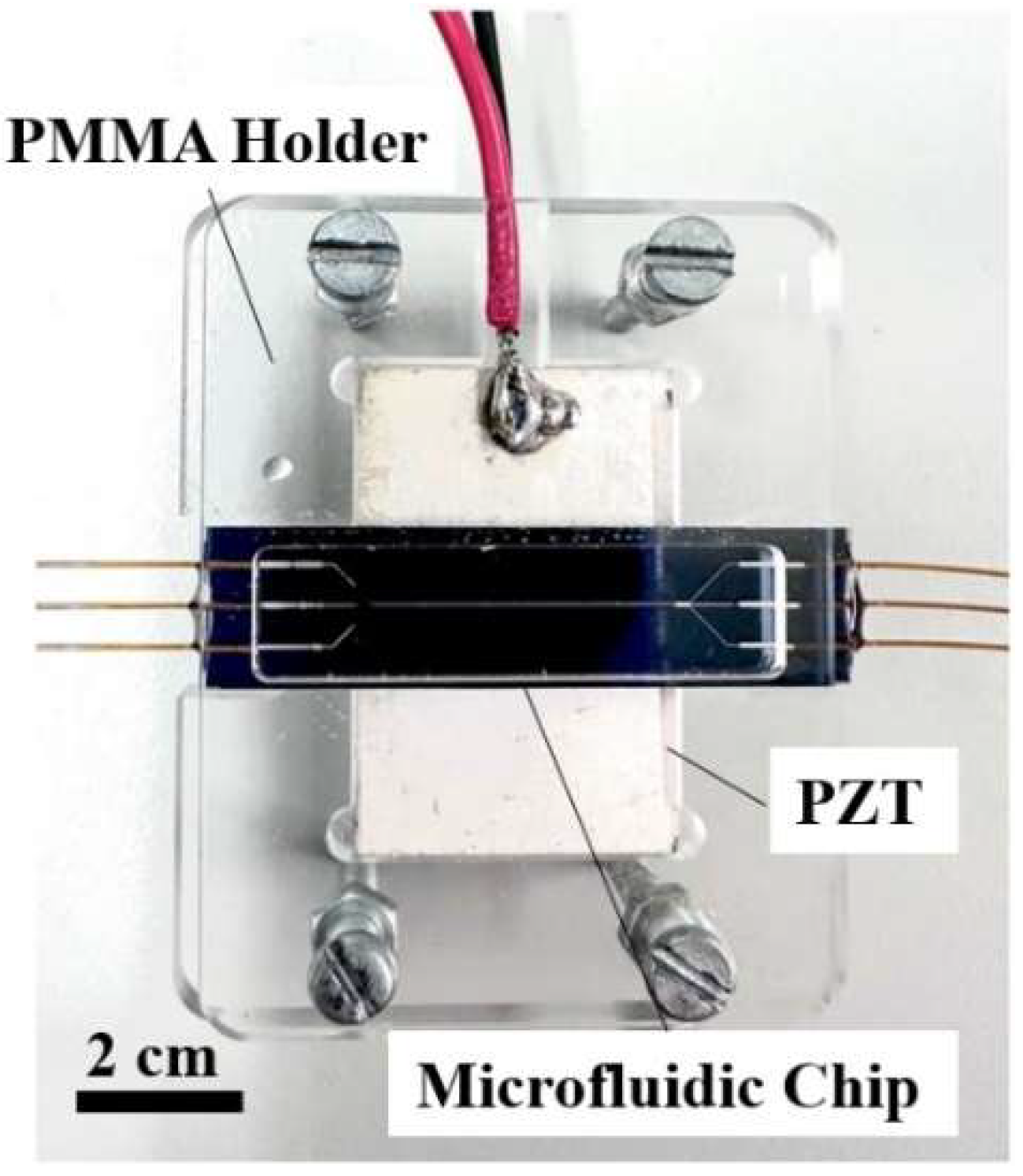
Figure 2.
The sharp corners are etched alongside the silicon microfluidic channel.
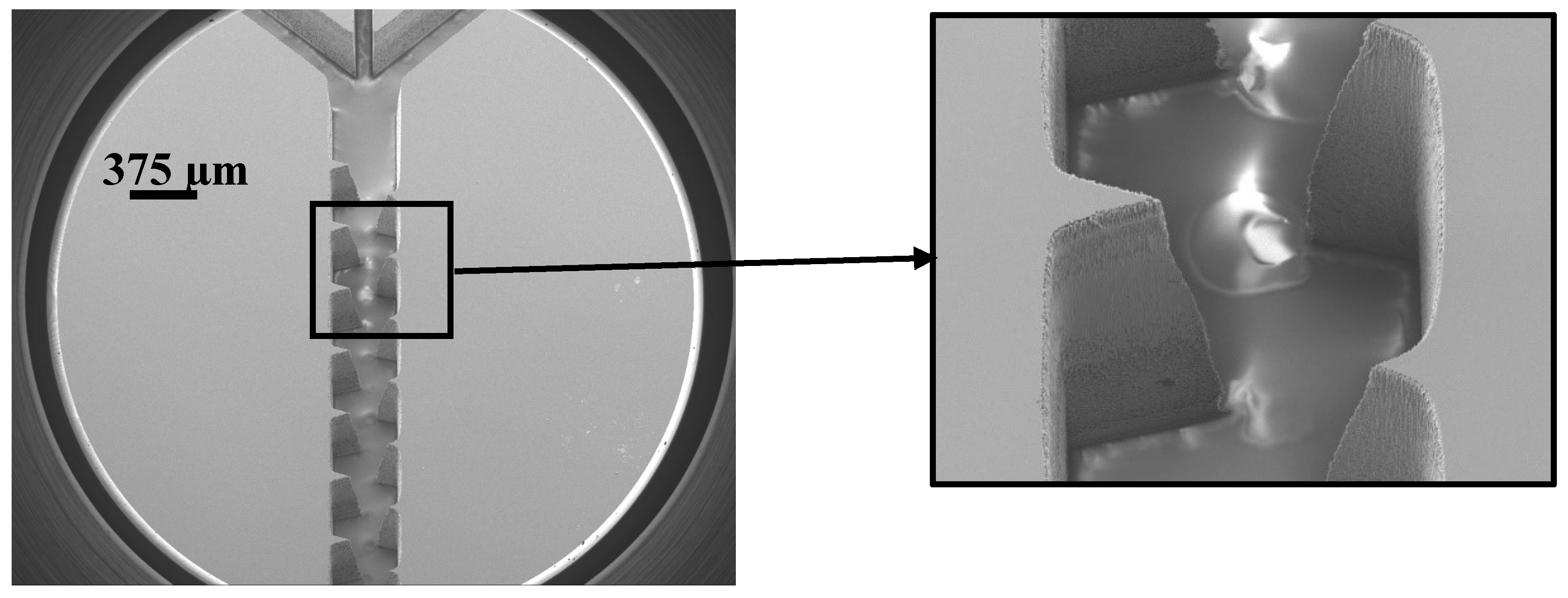
Figure 3.
Resulting streaming velocity for a range of PZT devices and applied frequencies.
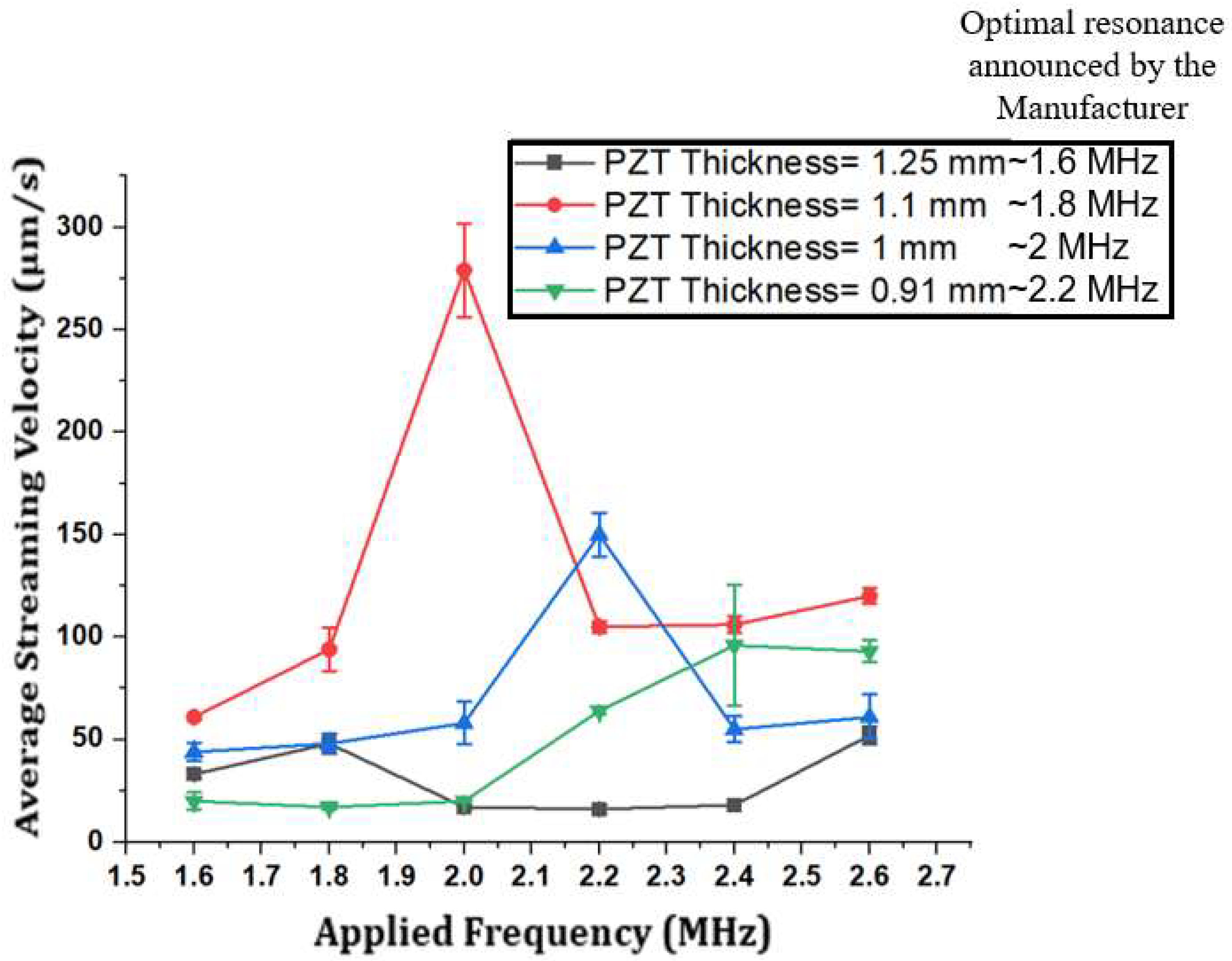
Figure 4.
Mixing efficiency experiments and a graph representing the results. The top image shows a continuous flow of water in the middle and fluorescent dye from both sides when the acoustics are off. The bottom image is when the acoustics have turned on, and the water and fluorescent dye are mixed. The graph extracted from MATLAB shows that the mixing efficiency reached almost 80 percent in 0.2 s.
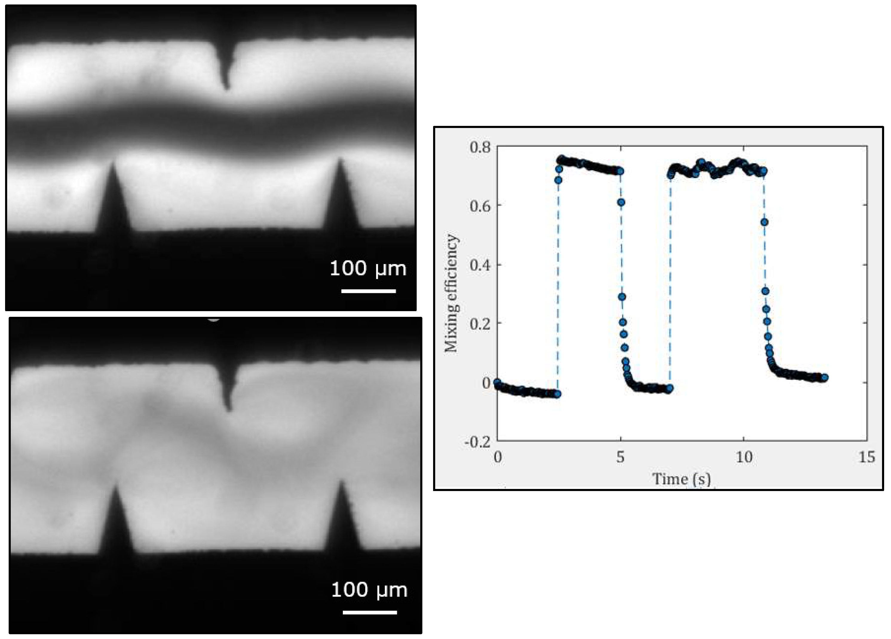
Figure 5.
Velocity vectors (red) of acoustic streaming around the sharp edges on the sidewall of the silicon channel when 7 V (left) and 20 V (right) voltage are applied. Please refer to SI (SI), S1 (7 V), and S2 (20 V) for the recorded experimental video.
Figure 5.
Velocity vectors (red) of acoustic streaming around the sharp edges on the sidewall of the silicon channel when 7 V (left) and 20 V (right) voltage are applied. Please refer to SI (SI), S1 (7 V), and S2 (20 V) for the recorded experimental video.
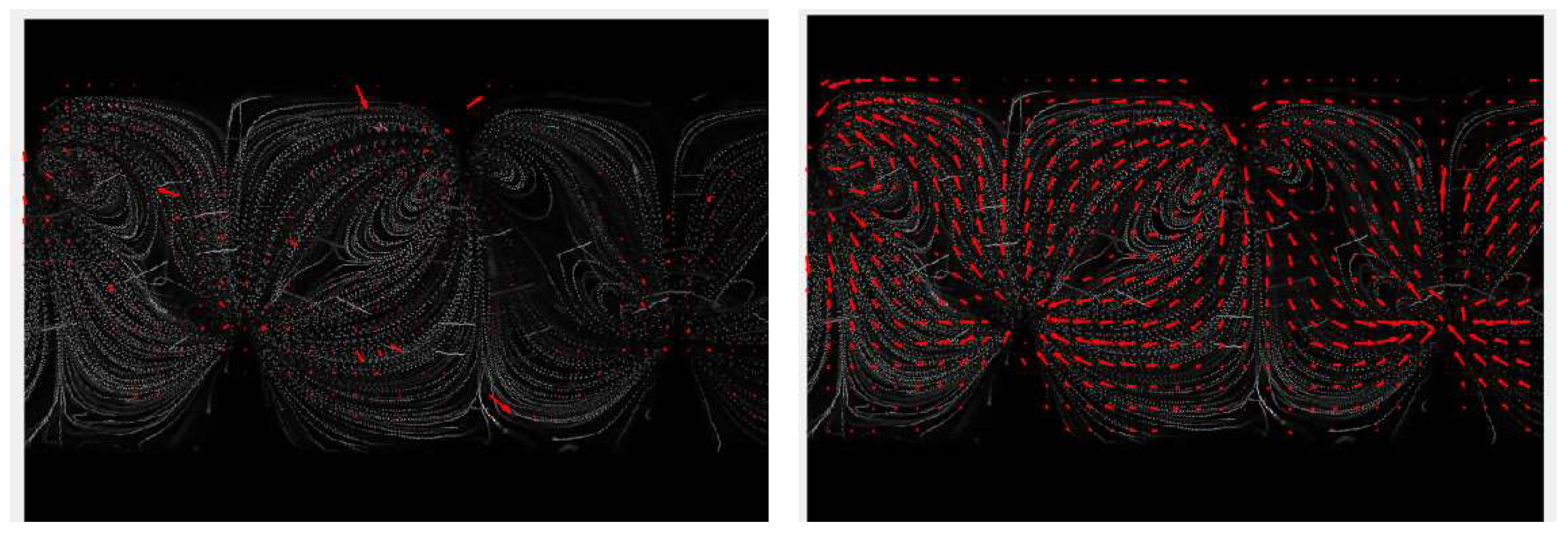
Figure 6.
Effect of different angles of sharp corners on average velocity magnitude. The images are taken from the chip from the top with an optical microscope. Channels with 10°, 20°, and (30°,40°, and 60°) result in 14, 8, and 1.5 times faster streaming consecutively compared to a straight channel with the same width and depth at 28 V.
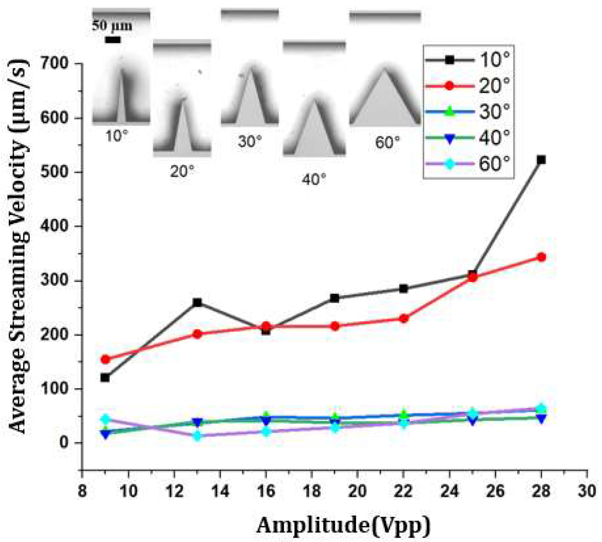
Figure 7.
Z-stacking of 1 µm polystyrene particles movement along the acoustic streaming around the sharp corners with numerous tip shapes.
Figure 7.
Z-stacking of 1 µm polystyrene particles movement along the acoustic streaming around the sharp corners with numerous tip shapes.
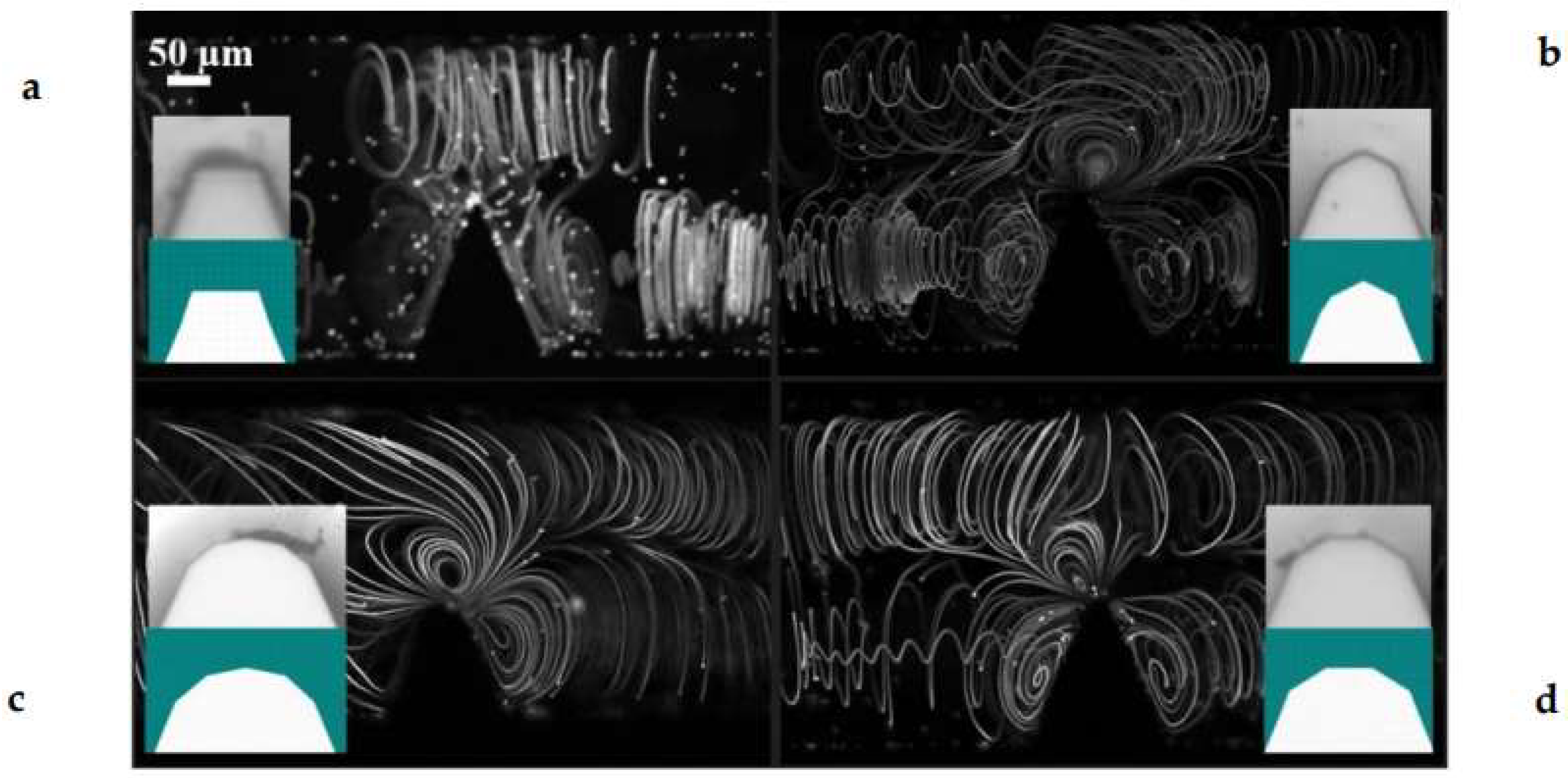
Figure 8.
Column graph of the effect of sharp tip and analysed area on the average velocity magnitude.
Figure 8.
Column graph of the effect of sharp tip and analysed area on the average velocity magnitude.
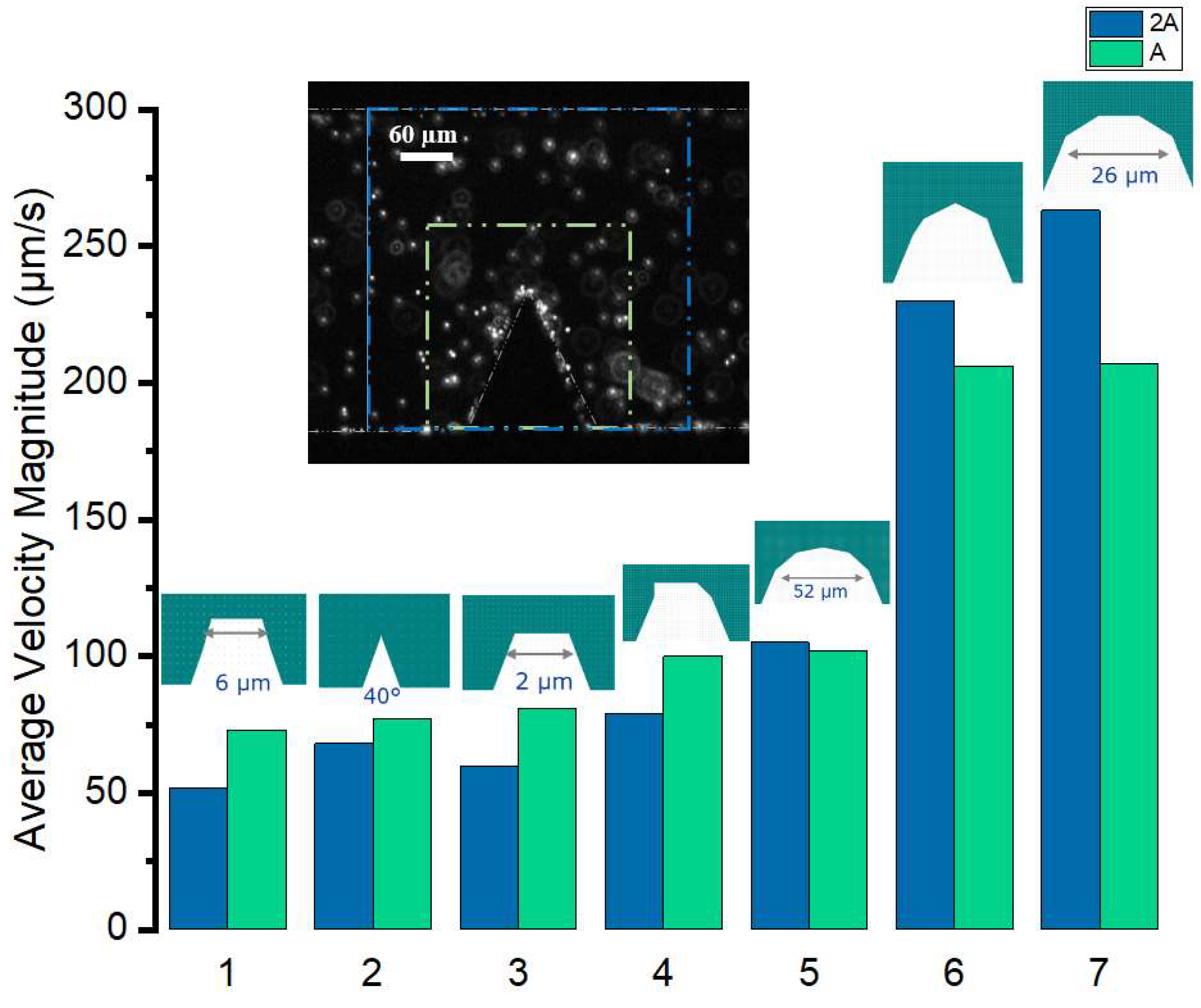
Figure 10.
a) Z-stacking of particle movements in the channel with circular pillars. The top-left image is all the frames since the start of streaming and pumping on top of each other. b) A cross-section of an etched feature showing the scallop formation that causes circulation in the circular pillars (number 1 in the figure is 0.80 µm and number 2 is 3.33 µm).
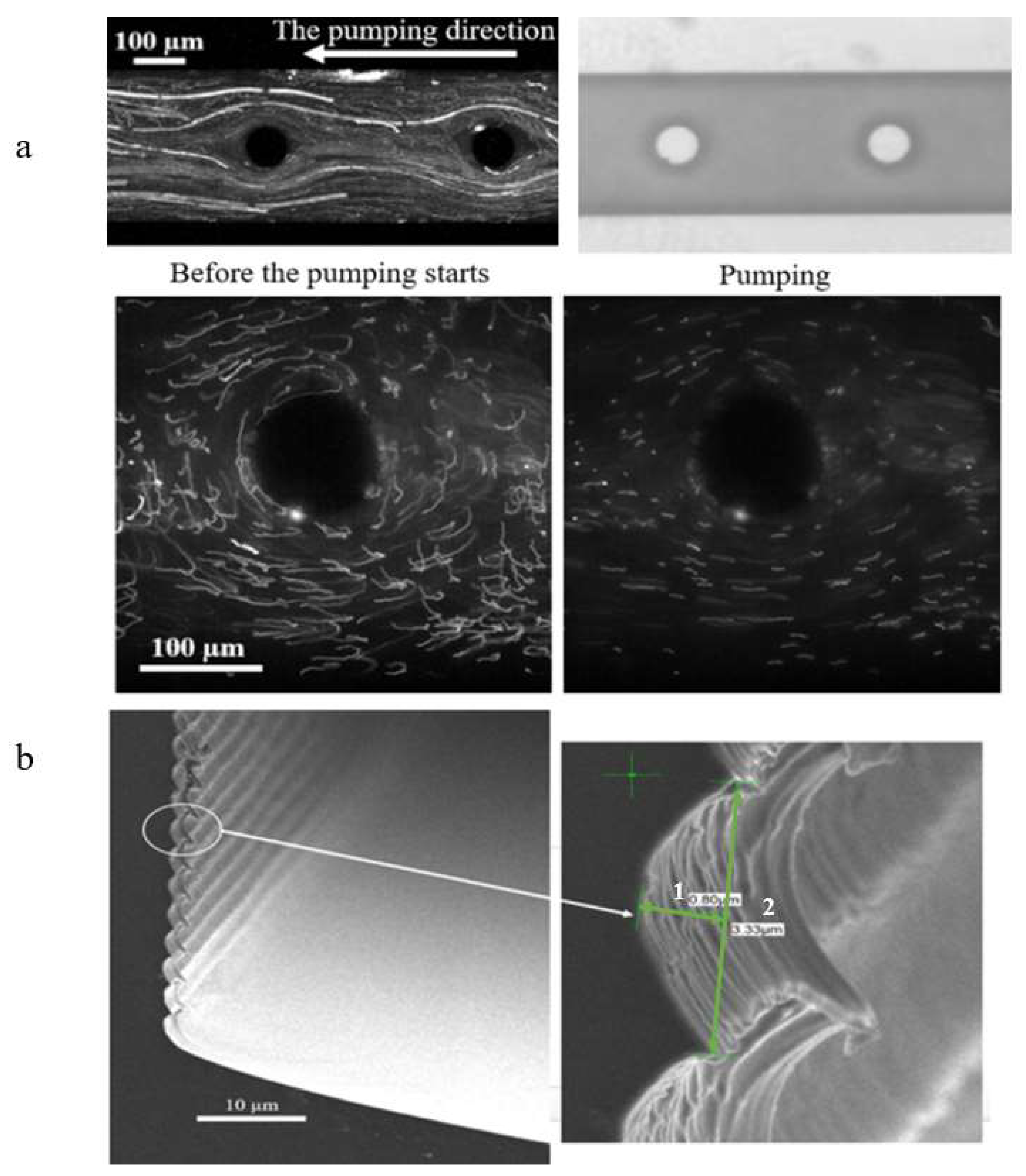
Figure 11.
a) Before the pumping starts, liquid movement patterns form inside the channel around each pillar, which increases with an increase in amplitude. The flow velocity in the channel with triangular pillars is higher than that with circular pillars. b) After the pumping effect starts, the pumping velocity increases with time. This increase is more significant in the channel with triangular pillars.
Disclaimer/Publisher’s Note: The statements, opinions and data contained in all publications are solely those of the individual author(s) and contributor(s) and not of MDPI and/or the editor(s). MDPI and/or the editor(s) disclaim responsibility for any injury to people or property resulting from any ideas, methods, instructions or products referred to in the content. |
© 2024 by the authors. Licensee MDPI, Basel, Switzerland. This article is an open access article distributed under the terms and conditions of the Creative Commons Attribution (CC BY) license (http://creativecommons.org/licenses/by/4.0/).
Copyright: This open access article is published under a Creative Commons CC BY 4.0 license, which permit the free download, distribution, and reuse, provided that the author and preprint are cited in any reuse.


