
Submitted:
27 August 2024
Posted:
30 August 2024
You are already at the latest version
Abstract
Carbon fiber-reinforced polymer (CFRP), noted for its outstanding properties including high specific strength and superior fatigue resistance, is increasingly employed in aerospace and other demanding applications. This study investigates the interactions between CFRP composites and high-energy lasers (HEL), with continuous wave laser powers reaching up to 120 kW. A novel automated sample exchange system, operated by a robotic arm, minimizes human exposure while enabling a sequence of targeted laser tests. High-speed imaging captures the rapid expansion of a plume consisting of hot gases and dust particles during the experiment. The research significantly advances empirical models by systematically examining the relationship between laser power, perforation times, and ablation rates. It demonstrates scalable predictions for the effects of high-energy laser radiation. Detailed examination of the damaged samples, both visually and via micro-focused computed X-ray tomography, offers insights into heat distribution and ablation dynamics, highlighting the anisotropic thermal properties of CFRP. Compression-after-impact (CAI) tests further assess the residual strength of the irradiated samples, enhancing the understanding of CFRP’s structural integrity post-irradiation. Collectively, these tests improve the knowledge of the thermal and mechanical behavior of CFRP under extreme irradiation conditions. The findings not only contribute to predictive modeling of CFRP's response to laser irradiation but also enhance the scalability of these models to higher laser powers, providing robust tools for predicting material behavior in high-performance settings.
Keywords:
high-energy laser
; CFRP
; laser impact
; compound material
; volume ablation
; scalability
; compression-after-impact
; laser damage
1. Introduction
Over the last 20 years, fiber lasers have rapidly evolved in terms of output power, beam quality and efficiency. Due to their compact solid-state design they are suitable for maintenance-free and portable applications. Fiber-guided beams can be robustly transported over long distances to laser optics or can be remotely used by an industrial robot. Furthermore, the near-IR wavelengths of fiber lasers are well absorbed by many materials that are used for production like various metals or plastics. All this has led to fiber lasers now dominating the market for industrial laser processing [1].
In recent years, the performance of continuous wave (CW) fiber lasers has increased significantly, making lasers in the 100 kW range commercially available [2,3]. Such powerful CW lasers are now used not only for industry but also for defence technology [4,5,6]. Although these systems are not usable over long distances due to their low beam quality, they are well suited to investigate HEL effects in a laboratory environment.
The interaction between HELs and carbon fiber-reinforced polymer (CFRP) composites is crucial in the aerospace and defense sectors, where material integrity under extreme conditions is critical. CFRP exhibits notably high thermal insulation properties. While the carbon fibers withstand high heat fluxes, the polymer matrix provides a low thermal resistance [8]. Therefore, understanding the effect of high-energy laser radiation on CFRP, especially with large beam diameters, is of particular interest [9,10,11,12].
Propagation of laser radiation over long distances is an important consideration for laser weapons. Laser beams can be scattered or absorbed by air molecules, water vapor, or dust [13,14,15]. In this study, we focus on the effect of the laser on the target. Considering our case with a maximum of 120 kW at the target location, it can be assumed that an actual directed energy laser system must have an output power of several hundred kilowatts tens of kilometers away due to propagation losses in the air. This loss depends strongly on the actual weather condition, in this rough estimation valid for a medium extinction and neglecting a decrease due to turbulence.
In the literature, welding processes in the range of 10-100 kW are extensively studied [16,17,18,19,20]. For example, Krichel et al. as well as Kawahito et al. analyzed process limits in laser beam welding of thick steel sheets using a 40 kW and 100 kW laser respectively [16,20]. Herzog et al. used a 30 kW Laser to cut CFRP with a focus on minimizing the heat affected zone and maximizing the feed rate of the cutting process [32]. These and similar studies with particular high laser powers are based on working with a small beam diameter well below 1 mm. In contrast to the studies in the literature, this work focuses more on the investigation of laser effects with extremely high laser powers and simultaneously large spot sizes. This aspect is not only important to understand the degradation of CFRP under HEL exposure, but also in the defense context, with CFRP as a representative material.
Various sources provide information on the thermal decomposition of CFRP and the resulting temperatures. Typically, the epoxy matrix begins to degrade at temperatures at around 300 °C, while the carbon fibers exhibit higher temperatures between 1000 and 3000 °C during final degradation stages [23,24,25,26]. Tranchard et al. conducted a study on decomposition processes under varying atmospheric conditions using thermogravimetric and FTIR measurements [22]. They provide a deeper insight into the damage behavior of CFRP and developing a kinetic decomposition model.
Numerical modelling has been instrumental in understanding the interaction between CFRP and high-energy laser sources. Chippendale et al. [26] and Joyce et al. [27] have modelled the thermal decomposition processes and effects of high-energy laser effects on polymers and composites, offering insights into the heat-affected zones and ablation dynamics. Further, Nan et al. demonstrated the influences of the laminated structure on ablation characteristics, emphasizing how layer orientation affects thermal and mechanical responses during laser exposure [28]. Ohkubo et al. simulated laser beam cutting of CFRP, revealing the complex interactions between laser parameters and material responses [29]. The study of Schmitt and Allheily deals with thermal development within CFRP structures under laser impact, highlighting the importance of thermal radiation between carbon layers at elevated temperatures [30]. While these numerical studies form a foundation, the focus of the current study is on empirical validation and extension of these models up to higher power levels, and thus detailed numerical modelling is beyond the scope of this paper.
In laser processing of CFRP composites, the choice between CW and pulsed lasers significantly influences the outcomes. While CW lasers offer higher cutting speeds and efficiency, they often lead to greater thermal damage; on the other hand, pulsed lasers provide better control of the heat-affected zone (HAZ), reducing thermal degradation at the cost of slower processing rates [31,32]. In addition to continuous and pulsed lasers, Quasi-Continuous Wave (QCW) fiber lasers offer a unique approach to managing the heat affected zone (HAZ) in CFRP cutting. Leone et al. conducted a study investigating the influence of process parameters such as pulse power, pulse duration, and overlapping factor on kerf geometry and HAZ, suggesting that by optimizing these parameters, it is possible to achieve minimal HAZ [33].
While the current state of the art provides a good overview of the impact processes of CW lasers on CFRP in the range up to a few kilowatts, empirical evidence at higher power scales is needed. To assess the behavior of CFRP under laser irradiation in previously unexplored power ranges, we conducted a parameter study with laser powers up to 120 kW. The study includes the design of a test environment that meets operational safety requirements for laser processing of CFRP. The test results include high-speed imaging to capture the process dynamics. The setup includes photodiode measurements for the detection of perforation times and for an automated laser shut-off mechanism and high-speed video recording for the visualization of the interaction effects. Micro-focused computed X-ray tomography (µ-CT) scans were performed after the exposure to analyze the ablation and delamination behaviour caused by the laser impact. Additionally, physical properties of the irradiated samples, such as residual strength, were evaluated using compression tests in accordance with compression after impact (CAI) test regulations.
2. Materials and Methods
The setup used in this study incorporates various improvements compared to our setup used in our previous work published in Wolfrum et al. [9]. The experimental setup is depicted in Figure 1. It utilized a CW infrared fiber laser with a wavelength of 1.07 μm, capable of delivering up to 120 kW (YLS-120000, IPG Photonics Corporation, Germany). The laser beam passed a collimator and was then focused using an adjacent lens with a focal length of 400 mm. The laser beam exhibits a beam intensity that closely resembles a Gaussian distribution, with a super-Gaussian exponent of 1.5. To protect the coated optics from dust, a cover was attached to the laser optics and purged with clean air. During the experimental series, the distance between the optics and the sample was adjusted to vary the beam diameter (D4σ) between 10 and 30 mm. The laser-matter interaction zone is captured using a high-speed framing camera (Phantom v1610, Vision Research Inc., USA).
The experimental setup featured several characteristics aimed to mitigate the risks associated with the combustion of CFRP. To minimize human exposure to potentially hazardous by-products of CFRP combustion, an automated sample exchange system operated by a robotic arm is utilized. This allowed for a sequence of laser tests to be conducted while ensuring safety. The concern regarding human exposure to hazardous by-products of CFRP combustion has been highlighted in studies by Lacroix et al. [10]. To capture smoke and fiber fragments generated during the experiments, an enclosed measurement box with additional ventilation was designed. This helped to maintain a controlled environment and prevent the dispersion of harmful substances. Furthermore, a shut-off automation system was implemented to immediately stop the laser irradiation after sample perforation using the automatic photodiode switch. This effectively limited the potential “afterburn effect” that could compromise experimental precision and safety.
With a parameter variation over a large laser power range (10-120 kW), different spot sizes (10-30 mm), sample thicknesses (2-6 mm), and two different materials (Hexply® M18-1/G939 and 8552/IM7), the aim of this study was to systematically investigate the effects of high-energy lasers on CFRP materials. The dimensions and lay-up of the samples were analog to dimensions of lay-ups used in [28]. Before testing, all samples were ground at the 100 mm wide edges to provide parallelism for the compression after impact (CAI) testing. Compressive strength after impact is measured according to DIN 65561 at an universal testing machine (Zwick-Roell, UPN 250 kN) with a cross-head speed of 1 mm/min. With selected samples micro-focused computed X-ray tomography (µ-CT) is carried out using a 300 kV micro-focus X-ray source (Phoenix VTOM XL300) and a GE Dynamic 41/100 detector. For the investigations up to six samples were combined to one package.
3. Results and Discussion
Direct CW laser irradiation of CFRP samples resulted in evaporation of the epoxy matrix and to some extent of the carbon fibers. This evaporation is evident from the emergence of a dust plume in front of the sample, extending up to half a meter. The expansion of the plume starts immediately after the laser emission is turned on, as observed in high-speed images (Figure 2). The experiment shown in Figure 2 was conducted using a laser power of 120 kW and a beam diameter of 20 mm on a 4 mm thick M18-1/G939 sample. In the following, this experiment will be used to show typical results of the series of experiments carried out.
The vapor plume contains ejected fragments of the fiber compound and smoke. Furthermore, the resin matrix is vaporized or decomposed due to the laser absorption. The continuous heating by the laser ionizes the combustion products, leading to a partially ionized matter with a temperature in the range of several thousand Kelvin, as described by Ma et al. [34]. In similar experiments conducted by Borchert et al. [11] on Glass–Fiber-Reinforced-Polymers (GFRP), temperature evolution was measured using a four-channel infrared detector system to overcome limitations of conventional pyrometers. Their results showed a temperature plateau at 2100 K to 2500 K at later time delays from the flame emission. Herr et al. [12] utilized high-speed thermal imagery and spectral analysis to characterize the plume generated in front of laser-irradiated CFRP plates, revealing a complex composition of organic products such as hydrocarbon gases and particles.
The CFRP samples were perforated after an irradiation time of 0,4-0,5 s for both materials. Figure 3 shows images of the damage zones obtained after the laser exposure. Distinct differences between the front and back surfaces of the tested samples is noticeable. First of all, the area of the ablated fibers on the front is roughly comparable to the applied laser beam diameter of 20 mm, while the perforated area on the back is only a few mm in size. Furthermore, the matrix surrounding the exposed area on the front side shows a heat affected zone (HAZ) with signs of vaporization beyond the direct impact area. The matrix around the perforation hole on the back, however, shows no visible signs of any thermal effects from the laser. The HAZ seems to decrease from the front to the back side of the sample. Another notable observation is that the damage zones often exhibit a conical shape, indicating a change in material removal behavior with increasing laser power. Anisotropic properties of CFRP as well as differences in thermal diffusion of the CFRP components contribute to both the formation of a conical shape and the extended HAZ. Specifically, the heat conductivity of graphite is 50 W/(m∙K), compared to only 0,2 W/(m∙K) for the polymer matrix, and vaporization occurs at 3300 °C for the fibers versus 350-500 °C for the matrix [24,31]. Hence, heat conduction occurs primarily along fibers, leading to vaporization of the matrix material outside of the laser impact zone, resulting in an extended HAZ with increasing irradiation times. For lower laser intensities, the heat conduction in the lower fiber layers causes the matrix to evaporate, while for higher laser intensities, the heat cannot be dissipated fast enough, resulting in evaporation of fibers and matrix within the HAZ. Remaining fibers act as a shield for underlying layers. Consequently, lower layers absorb a smaller area of the laser beam, which in turn results in a more pronounced conical shape.
The perforation times detected during the experiments are used as a critical measure of material resistance to laser penetration. It is observed that the perforation time decreased with increasing laser power, as shown in Figure 4 using a double-logarithmic representation. The dependence of perforation time on laser power holds true for all tested beam diameters and can be described by a power law:
which is represented as a fit in Figure 4. The slopes of the fits varied between values of a= -1.13 and -1.06. The slopes determined for smaller and larger beam diameters are slightly higher (a = -1.33 to -1.17 for Ø = 30 mm) and lower (a = -1.08 to -0.93 for Ø = 10 mm) respectively. These values correspond to the exponents for the power functions when choosing a double logarithmic representation of the data. In particular, the 8552/IM7 material showed increased resistance to laser irradiation due to its higher fiber content. This emphasizes the influence of material composition on the damage threshold and resilience of CFRP.
In [9] scaling laws are shown for the burn-through-times of CFRP samples for laser powers up to 10 kW. With the increase of laser power by one order of magnitude here now, this scaling law is again confirmed. This indicates that an extrapolation beyond and interpolation between the investigated laser powers seems to be valid. Based on the confirmed correlation of perforation time and laser power via a power law, an empirical model can be derived. The model can be used to predict the failure behavior of CFRP samples across a wide range of laser power levels.
Furthermore, the results of the parameter study are used to establish a correlation between the perforation time and the expected material removal due to laser irradiation. The volume damage was quantitatively assessed using a simplified model, approximating the ablated volume at perforation time as a cylindrical shape. In this model, the diameter of the cylinder corresponds to the laser spot diameter D4σ, and the depth is defined by the thickness d of the sample, thus:
Based on this approximation, a linear relationship can be determined between the logarithm of the damaged volume and the logarithm of the perforation time for each laser power, as shown in Figure 5 for the tested material M18-1/G939.
While some individual values for a laser power of 10 kW show a slight deviation, the values for higher laser powers can be properly described by the linear fit in Figure 5, which represents a power law when plotted linearly. A possible explanation for the higher variance of the values at a low power level is the effect of carbonization of the CFRP surface and upper matrix layers before sublimation, especially in experiments with large beam diameters. These carbonized layers act as a shield and prevent the subjacent fibers from being exposed to the incident laser light. Allheily et al. conducted experiments using a 10 kW fiber laser and observed that the delamination of CFRP plies, caused by rapid ablation of the matrix and bending of the fibers, decreases the thermal conductiviy resulting in a decreased energy deposition in the underlying material [10]. This aspect is of particular importance in the context of resistance against laser irradiated damage.
To explore the relationship between laser power and the rate of volume damage r_vol, we calculated the volume removal rate, defined as the volume of material ablated per unit time. This is again based on the assuption of a cylicdrical hole with the same diameter as the laser spot, which yields the approximation:
This analysis provides a direct measure of how the efficiency of material removal scales with increasing laser power.
The values for the volume removal rate calculated from experimental data and equation (3) are shown by the symbols in in Figure 6. As laser power increases, the volume removal rate also increases, indicating that higher energy inputs significantly enhance the efficiency of ablation. The sold lines represent a linear fit indicating that the relation between volume removal rate and laser power is well described by a linear relation. Consequently, within certain limits, the perforation time for arbitrary laser spot diameters D4σ and sample thickness can be calculated directly from linear fit shown in Figure 6.
Additionally, when considering the broader context of a high-energy laser (HEL) weapon, it becomes evident that managing laser power is vital in controlling the extent of damage and the efficiency of material removal. These results emphasize the importance of parameter optimization in laser processing of CFRP, providing a foundation for further experimental design and technological advancements in laser processing technologies.
The developed empirical models for volume damage and volume removal rate offer significant implications for understanding the structural integrity and vulnerability of CFRP materials in scenarios involving intense laser exposures, thereby enhancing predictive capabilities for both, industrial applications and defense strategies against high-energy laser threats.
µCT-scans were utilized to visualize and analyze the damage morphology of CFRP samples, providing a comprehensive understanding of the extent of laser-induced damage. Figure 7 displays cross-sections of CT images of CFRP panels irradiated with different laser powers and beam diameters. The effect of laser spot size is evident: with a smaller spot size of 10 mm, rapid perforation leads to localized damage confined closely to the irradiated area, indicating minimal lateral heat transfer. Conversely, larger spot sizes at the same power levels result in extensive vaporization of the epoxy matrix around the beam impact area, leading to delamination and potential structural failure as the matrix vaporizes and leaves the fibers unsupported. Hence, the HAZ is much larger. At lower powers (30 kW), a large HAZ with significant material degradation is observed. The matrix material seems to be decomposed or removed while the carbon fibers remained partially intact. This indicated an incomplete ablation. In contrast, at the maximum laser power of 120 kW, nearly all fibers within the area of the laser spot size were completely decomposed, suggesting a threshold of energy input above which total fiber decomposition occurs.
The scans reveal that, depending on the applied laser intensity, laser penetration can occur so rapidly that the heat does not significantly dissipate beyond the irradiated area. This observation matches the previously described damage analysis of irradiated samples, shown in Figure 3.
As already described, the conical shape of the ablated volume can be attributed varying absorption and thermal conductivity characteristics between the composite’s constituents. As noted in studies by Herr et al. [12] and Allheily et al. [10], the thermal gradients created by laser irradiation result in differential rates of heat dissipation within the material, promoting a conical ablation profile. The delamination process allows the heat to propagate more extensively along the fiber direction compared to a propagation into the depth of the samples. This further enhanced the appearance of the conical shaped holes.
When considering different material thicknesses (data not presented here), it is apparent that the conical shape of the ablated area is particularly pronounced in thicker CFRP panels. Similarly, Herzog et al. found that laser cutting of CFRP can maintain precise kerf sizes up to a certain depth, beyond which shadowing effects impede further penetration [32].
When examining the total ablated and delaminated volumes, it is apparent that the extent of material removal remains consistent across both, lower and higher power settings. This observation highlights the efficiency of the laser ablation process, where increased power does not necessarily result in greater material removal but rather a broader spread of thermal effects, as also discussed by Sobri et al. in the context of laser machining dynamics [35].
The results shown in Figure 8 indicate that the residual strength primarily depends on the volume of the material ablated, particularly the matrix. Thicker samples, such as the 6 mm panels, exhibit higher performance across various spot sizes, indicating that thicker samples are more resistant to damage and retain more residual strength. In general, larger laser spot sizes are associated with a reduction in compressive strength.
An important aspect to consider is the observed delamination, which is more prominent with larger beam diameters and lower laser powers. Delaminated fibers, although still physically present, no longer contribute significantly to the structural integrity of the material. Their mechanical connection to the composite has been compromised, reducing their ability to carry loads and consequently decreasing the residual strength of the composite.
Regarding the different applied laser powers, a decline in residual strength can be noted with increasing energy input from the laser. However, there is no clear correlation to the test parameters set, indicating a complex interplay of factors. The parameters, specifically laser power and spot size, are part of a multidimensional space that affects the damage characteristics and, subsequently, the mechanical properties of CFRP. The impact of laser irradiation on CFRP is influenced by a variety of factors including thermal conductivity of the fibers and matrix. Based on the CT images and damage patterns shown, variations of the laser parameters can result in varied heterogeneous damage regions within the material. The lack of clear correlation observed in the test results underscores the nuanced interactions within this parameter space.
4. Conclusions
This study contributes to the advancement of understanding CFRP under CW laser exposures up to 120 kW. The research fills a gap in the existing literature by comprehensively exploring the interaction between intense laser radiation and CFRP structures in the range of 10 kW to 120 kW. Through a parameter study that incorporates variations in material, laser power, spot size, and sample thickness, this research provides valuable insights into the reaction of the material to extreme energy exposures.
Building upon foundational work by Wolfrum et al. [9], which developed initial empirical models for CFRP failure under laser irradiation of up to 10 kW, this study expands the experiments up to 120 kW. Furthermore, an automated sample exchange system was introduced. This advancement enhances safety and efficiency while enabling systematic studies of the material’s response to high-power laser exposures. The results from this series of tests have provided insights into the failure threshold of CFRP by measuring perforation times across various laser intensities. The perforation times showed a clear dependence on laser power, which could be described by power-law relationships with exponent values between -1.13 and -1.06 – see Equation (1) There are clear trends for the correlation between volume damage and perforation times, which could be extrapolated for even higher power classes. Based on this relationship, volume removal rates were derived for which a linear dependence on the applied laser power could be shown. In summary, it can be stated that the empirical models have been further developed on the basis of the perforation times determined and, in particular, the scalability for much higher laser powers was verified.
Our study also examined the responses of two different types of CFRP materials (M18-1/G939 and 8552/IM7) to laser exposure, emphasizing the importance of variations in fiber content. The degradation of fibers were observed through damage pattern assessment and µCT-scans. The evaporation of the matrix and delamination of fibers are particularly critical aspects, especially in applications where material integrity is crucial. The ability to predict and mitigate such damage is essential for ensuring the reliability and safety of CFRP components in demanding applications. The residual strength of the CFRP samples, evaluated by tests in accordance to CAI procedures, was predominantly influenced by the volume of material ablated, particularly the matrix. Delamination, especially with larger beam diameters, significantly impaired the structural integrity of the composite and contributed to a reduction in compressive strength. The findings enhance the understanding of the dynamics between laser energy and material properties, enabling more effective control of the laser process and potentially leading to significant technological advancements.
Future studies could explore variations in fiber content within CFRP samples to investigate how material composition influences damage thresholds and vulnerability. Such studies would further refine the understanding of material behavior under high-energy laser impacts, ensuring the continued reliability and safety of CFRP components in demanding applications.
Supplementary Materials
The following supporting information can be downloaded at the website of this paper posted on Preprints.org.
Author Contributions
Conceptualization, S.S.; methodology, S.S. and J.W.; formal analysis, S.S.; J.W., D.H., S.R., M.L., J.O. investigation, S.S., D.H., S.R.; writing—original draft preparation, S.S.; writing—review and editing, S.R., J.W., J.O.; funding acquisition, M.L., J.O. All authors have read and agreed to the published version of the manuscript.
Funding
We acknowledge financial support by the Bundesamt für Ausrüstung, Informationstechnik und Nutzung der Bundeswehr (BAAINBw), Koblenz, Germany.
Conflicts of Interest
The authors declare no conflicts of interest.
References
- Belforte, David A. The Global Market for Industrial Laser Processing. PhotonicsViews, 2020, 17 (2), pp. 35-37. [CrossRef]
- Shcherbakov, E. A.; Fomin, V. V.; Abramov, A. A., Ferin, A. A.; Mochalov, D. V.; Gapontsev, V. P. Industrial grade 100 kW power CW fiber laser. In Advanced Solid-State Lasers Congress, 2013; OSA. [CrossRef]
- Nissenbaum, A.; Armon, N.; Shekel, E., B. Dynamic beam lasers based on coherent beam combining, Fiber Lasers XIX: Technology and Systems, SPIE, 2022. [CrossRef]
- Jung, M.; Riesbeck, Th.; Schmitz, J.; Baumgärtel, Th.; Ludewigt, K.; Graf, A. High energy laser demonstrators for defense applications. XXI International Symposium on High Power Laser Systems and Applications, SPIE Proceedings, 2016. [CrossRef]
- Lyubomir, L.; Edmunds, T.; Risham, S.G. Applications of Laser Technology in the Army, Journal of Defense Management, 2021, 11 (Article 210).
- Karr, T.; Trebes, J. The new laser weapons, Physics Today, 77 (1), pp. 32–38. [CrossRef]
- Smith, F. G.; Accetta, J. S.; Shumaker, D.L. The infrared & electro-optical systems handbook, Vol. 2: atmospheric propagation of radiation. Ann Arbor, Michigan, Bellingham, Washington: Infrared Information Analysis Center, SPIE Optical Engineering Press.
- Bibinger, J.; Eibl, S.; Gudladt, H.-J. Ply-Resolved Quantification of Thermal Degradation in Carbon Fibre-reinforced Polymers, Journal of Composite Materials, 2023, 57 (6), S. 1057–1072. [CrossRef]
- Wolfrum, J.; Eibl, S.; Oeltjen, E.; Osterholz, J.; Wickert, M. High-energy laser effects on carbon fiber reinforced polymer composites with a focus on perforation time, Journal of Composite Materials, 2021, 55 (16), pp. 2249-2262. [CrossRef]
- Allheily, V.; Lacroix, F.; Eichhorn, A.; Merlat, L.; L’Hostis, G.; Durand, B. An experimental method to assess the thermo-mechanical damage of CFRP subjected to a highly energetic 1.07 μm-wavelength laser irradiation, Composites Part B: Engineering, 92, pp. 326-331. [CrossRef]
- Borchert, H.; Allheily, V.; Merlat, L.; Schmitt, R. Time resolved spectroscopic temperature measurement techniques during CW-laser matter interaction of glass–fiber-reinforced-polymers (GFRP), High Power Lasers: Technology and Systems, Platforms, Effects III, Proc. of SPIE Vol. 11162, 2019. [CrossRef]
- Herr, N. C.; Gonzales, A. E.; Perram, G. P. Kinetics, evolving thermal properties, and surface ignition of carbon fiber reinforced epoxy composite during laser-induced decomposition, Polymer Degradation and Stability, 2018, 152, pp. 147-161. [CrossRef]
- Smith, Frederich G.; Accetta, Joseph S.; Shumaker, David L. The infrared & electro-optical systems handbook, vol. 2: atmospheric propagation of radiation, Ann Arbor, Michigan, Bellingham, Washington: Infrared Information Analysis Center, SPIE Optical Engineering Press, 1993.
- Sprangle, P.; Hafizi, B. High-power, high-intensity laser propagation and interactions, Physics of Plasmas, 2014, 21 (5). [CrossRef]
- Fante, R.L. Electromagnetic beam propagation in turbulent media: An update, Proc. IEEE, 68 (11), pp. 1424-1443. [CrossRef]
- Krichel, T.; Olschok, S.; Reisgen, U. Extension of the process limits for laser beam welding in vacuum of thick-walled steel sheets, Procedia CIRP, 2022, 111, pp. 453-456. [CrossRef]
- Katayama, S.; Mizutani, M.; Kawahito, Y.; Sumimori, S. I. D. Fundamental research of 100 kW fiber laser welding technology, Proceedings of the Lasers in Manufacturing Conference (LiM), 2015, Munich.
- Pricking, A.; Kaiser, E., Papastathopoulos, E., Stambke, M., Bruestle, R.; Broghammer, G.; Tillkorn, C.; Gottwald, T.; Metzger, B., Schad; S.-S., Albers, K. Welding with ultra-high-power cw lasers, 12th CIRP Conference on Photonic Technologies (LANE 2022), 2022.
- Reich, S.; Goesmann, M.; Heunoske, D.; Schäffer, S.; Lueck, M.; Wickert, M.; Osterholz, J. Change of dominant material properties in laser perforation process with high-energy lasers up to 120 kilowatt, Scientific reports, 2023, 13 (1), 21611. [CrossRef]
- Kawahito, Y.; Wang, H.; Katayama, S.; Sumimori, D. Ultra high power (100 kW) fiber laser welding of steel, Optics letters, 2018, 43 (19), pp. 4667-4670. [CrossRef]
- Herzog, D.; Schmidt-Lehr, M.; Canisius, M.; Oberlander, M.; Tasche, J.-P.; Emmelmann, C. Laser cutting of carbon fiber reinforced plastic using a 30 kW fiber laser., Journal of Laser Applications, 2015, 27 (S2), 8001, pp. 3275. [CrossRef]
- Tranchard, P.; Duquesne, S.; Samyn, F.; Estèbe, B.; Bourbigot, S. Kinetic analysis of the thermal decomposition of a carbon fibre-reinforced epoxy resin laminate, Journal of Analytical and Applied Pyrolysis, 2017, 126, pp. 14-21. [CrossRef]
- Bibinger, J.; Eibl, S.; Gudladt, H.-J. Influence of Low and Extreme Heat Fluxes on Thermal Degradation of Carbon Fibre-reinforced Polymers, Applied Composite Materials, 2022, 29 (5), pp. 1817-1840. [CrossRef]
- Wu, C.-W.; Wu, X.-Q.; Huang, C.-G. Ablation behaviors of carbon reinforced polymer composites by laser of different operation modes, Optics & Laser Technology, 2015, 73 (2), pp. 23-28. [CrossRef]
- Zhang, Y. X.; Zhu, Z.; Joseph, R.; Shihan, I. J. Damage to aircraft composite structures caused by directed energy system: A literature review, Defence Technology, 2021, 17 (4), pp. 1269-1288. [CrossRef]
- Chippendale, R. D.; Golosnoy, I. O.; Lewin, P. L. Numerical modelling of thermal decomposition processes and associated damage in carbon fibre composites, Journal of Physics D: Applied Physics, 2014, 47 (38), 385301. [CrossRef]
- Tresansky, A. C.; Joyce, P.; Radice, J.; Watkins, J. Numerical modeling of high-energy laser effects in polymer and composite materials, Journal of Directed Energy, 2014, 5, 2, pp. 137–158.
- Nan, P.; Shen, Z.; Han, B.; Ni, X. The influences of laminated structure on the ablation characteristics of carbon fiber composites under CW laser irradiation, Optics & Laser Technology, 2019, 116 (2), pp. 224–231. [CrossRef]
- Ohkubo, T.; Tsukamoto, M.; Sato, Y. Numerical Simulation of Laser Beam Cutting of Carbon Fiber Reinforced Plastics, Physics Procedia, 2014, 56 (8), pp. 1165–1170. [CrossRef]
- Schmitt, R.; Allheily, V. Modelling the heating process of CFRP by cw-laser radiation with special focus on the heat transfer by thermal radiation between the carbon fibers, Procedia CIRP, 2018, 74 (5), pp. 562–567. [CrossRef]
- El-Hofy, M. H.; El-Hofy, H. Laser beam machining of carbon fiber reinforced composites: a review, International Journal of Advanced Manufacturing Technology, 2019, 101 (9-12), pp. 2965–2975. [CrossRef]
- Herzog, D.; Schmidt-Lehr, M.; Oberlander, M.; Canisius, M.; Radek, M.; Emmelmann, C. Laser cutting of carbon fibre reinforced plastics of high thickness, Materials & Design, 2016, 92, pp. 742–749. [CrossRef]
- Leone, C.; Mingione, E.; Genna, S. Laser cutting of CFRP by Quasi-Continuous Wave (QCW) fibre laser: Effect of process parameters and analysis of the HAZ index, Composites Part B: Engineering, 224 (2), pp 109-146. [CrossRef]
- Ma, Y.; Xin, C.; Zhang, W.; Jin, G. Experimental Study of Plasma Plume Analysis of Long Pulse Laser Irradiates CFRP and GFRP Composite Materials, Crystals, 2021, 11 (5), S. 545. [CrossRef]
- Sobri, S. A.; Heinemann, R.; Whitehead, D.; Amini, M. H. Mo.; Mohamed, M. Damage to Carbon Fiber Reinforced Polymer Composites (CFRP) by Laser Machining: An Overview, Machining and Machinability of Fiber Reinforced Polymer Composites, Vol. 3. Singapore: Springer Singapore (Composites Science and Technology), 2021, pp. 281–297.
Figure 1.
Experimental setup includes an automated sample exchange, operated by a robotic arm.
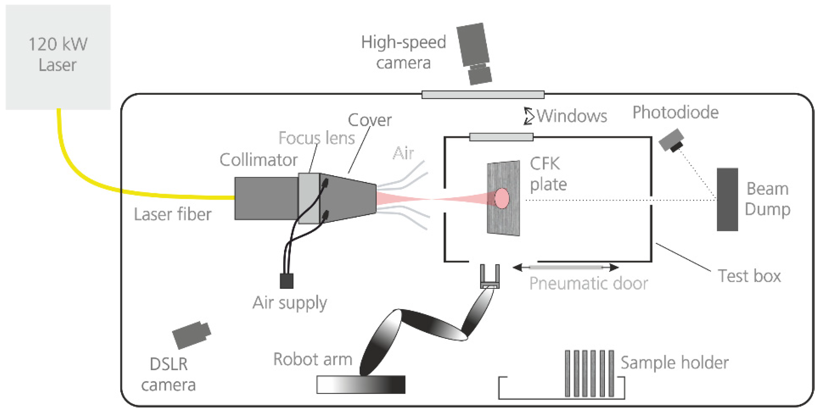
Figure 2.
A gas cloud expands rapidly caused by laser irradiation of a CFRP plate with 120 kW and a beam size of 20 mm. The plate is perforated after 0,4 s.
Figure 2.
A gas cloud expands rapidly caused by laser irradiation of a CFRP plate with 120 kW and a beam size of 20 mm. The plate is perforated after 0,4 s.
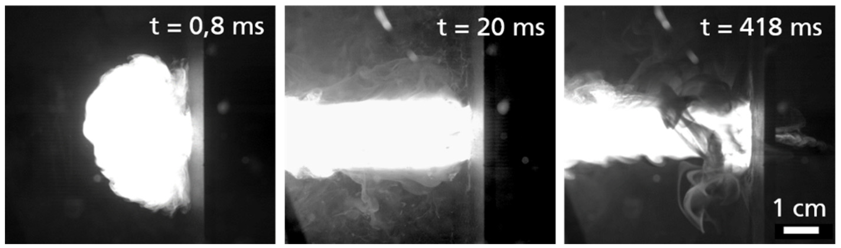
Figure 3.
Damage zones of irradiated CFRP samples of two tested materials (P = 120 kW, Ø = 20 mm, d = 4 mm). The heat affected zone (HAZ) extends to areas outside the applied laser spot.
Figure 3.
Damage zones of irradiated CFRP samples of two tested materials (P = 120 kW, Ø = 20 mm, d = 4 mm). The heat affected zone (HAZ) extends to areas outside the applied laser spot.
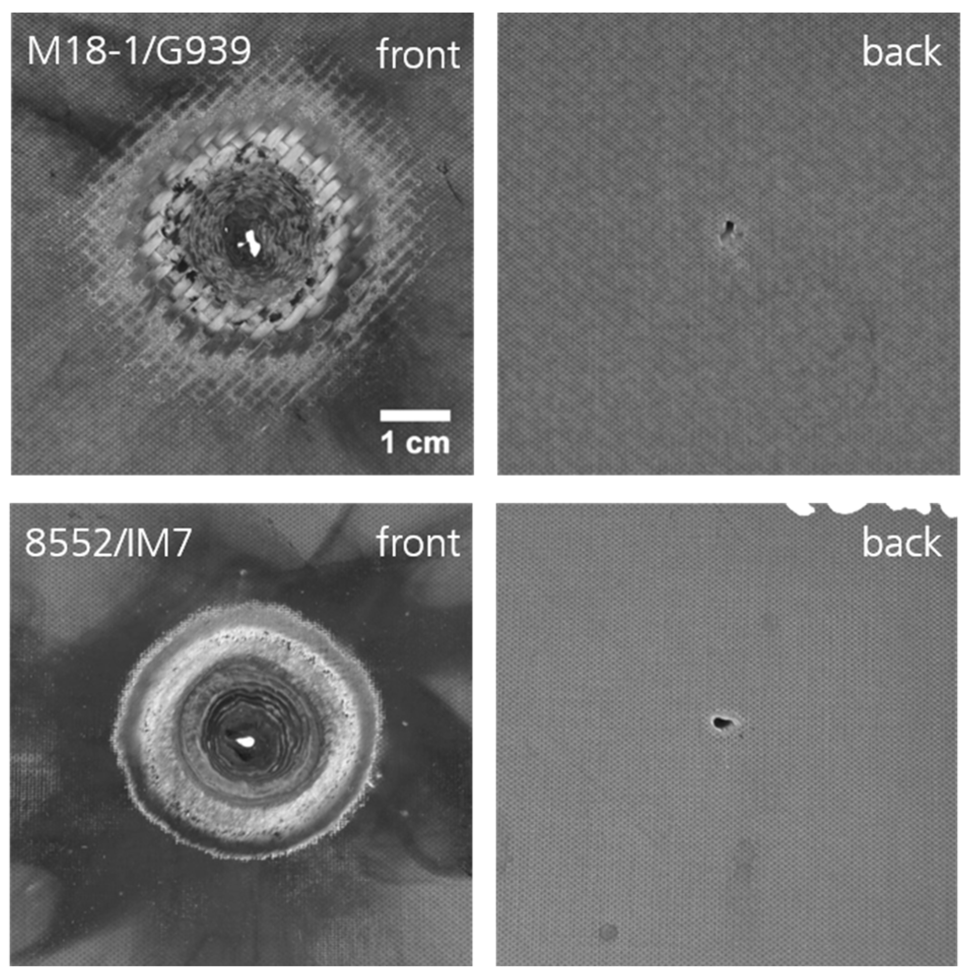
Figure 4.
Perforation times as a function of laser power in a double-logarithmic representation for a beam diameter of 20 mm and different sample thicknesses d. In this diagram, a linear decrease of the logarithm of the perforation time with increase of the logarithm of the laser power can be observed, represented by the solid and dashed lines.
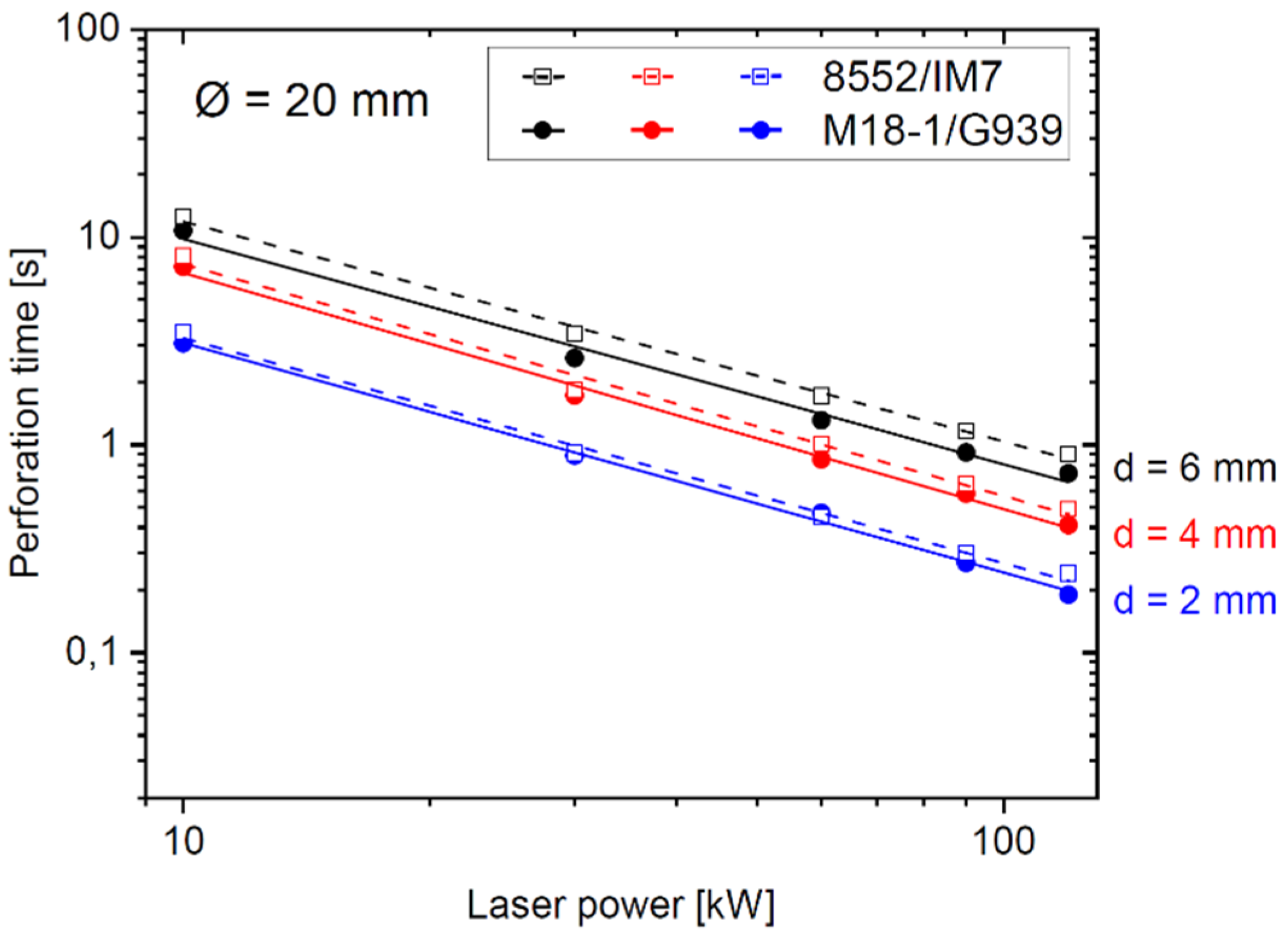
Figure 5.
Volume damage as a function of perforation time in a double-logarithmic representation for various laser powers.
Figure 5.
Volume damage as a function of perforation time in a double-logarithmic representation for various laser powers.
Figure 6.
Volume removal rate as a function of laser power. Symbols: r_vol determined from experimental data and Equation (3). Lines: linear fit.
Figure 6.
Volume removal rate as a function of laser power. Symbols: r_vol determined from experimental data and Equation (3). Lines: linear fit.
Figure 7.
µCT-scan cross-sections of irradiated CFRP samples reveal details of the heat-affected-zone and the delamination of fibers. The holes created have a conical shape (M18-1/G939, d = 6 mm).
Figure 7.
µCT-scan cross-sections of irradiated CFRP samples reveal details of the heat-affected-zone and the delamination of fibers. The holes created have a conical shape (M18-1/G939, d = 6 mm).
Figure 8.
Residual compressive strength of laser irradiated CFRP samples determined in accordance to the Compression After Impact procedure.
Figure 8.
Residual compressive strength of laser irradiated CFRP samples determined in accordance to the Compression After Impact procedure.
Disclaimer/Publisher’s Note: The statements, opinions and data contained in all publications are solely those of the individual author(s) and contributor(s) and not of MDPI and/or the editor(s). MDPI and/or the editor(s) disclaim responsibility for any injury to people or property resulting from any ideas, methods, instructions or products referred to in the content. |
© 2024 by the author. Licensee MDPI, Basel, Switzerland. This article is an open access article distributed under the terms and conditions of the Creative Commons Attribution (CC BY) license (https://creativecommons.org/licenses/by/4.0/).
Copyright: This open access article is published under a Creative Commons CC BY 4.0 license, which permit the free download, distribution, and reuse, provided that the author and preprint are cited in any reuse.


