
Submitted:
23 August 2024
Posted:
27 August 2024
You are already at the latest version
Abstract
This paper addresses the challenges faced by icebreakers in polar environments, particularly the difficulty in sensing underwater ice formations when navigating through thick ice layers, which often results in suboptimal icebreaking effectiveness. To overcome these challenges, this paper introduces a novel underwater robot equipped with both sensing and ice-breaking capabilities. We propose a path planning method for icebreaking that leverages the synergistic capabilities of the Safe Particle Swarm Optimization and Genetic Algorithm (GA-SPSO). The GA-SPSO algorithm integrates the global search prowess of the particle swarm optimization with the local optimization strength of the genetic algorithm, enabling efficient and adaptive path planning in complex ice environments. The underwater unmanned vehicle (UUV)-assisted icebreaking approach developed here utilizes the UUV's flexibility and high-precision environmental sensing to provide real-time optimization suggestions for icebreaker navigation paths. Simulation results demonstrate that the GA-SPSO algorithm not only effectively circumvents hazardous areas but also significantly reduces the energy consumption and operational time of icebreakers, thereby enhancing the safety and stability of navigation. When compared to the conventional Safe Particle Swarm Optimization (SPSO), our approach shows marked improvements in path length, convergence speed, and obstacle avoidance capabilities, significantly enhancing the success and efficiency of polar navigation missions.
Keywords:
polar navigation
; underwater unmanned vehicle (UUV)
; safe particle swarm optimization (SPSO)
; ice layer sensing
; genetic algorithm (GA)introduction
1. Introduction
The increasing impact of climate change, alongside the expanding demand for exploitation in the polar regions, has elevated polar navigation to a global concern. As the significance of polar regions grows, these areas are emerging as focal points for global governance, maritime routes, and resource exploration [1,2]. The polar regions are not only abundant in natural resources but also hold strategic geopolitical significance. However, navigating these regions presents considerable challenges due to the ice cover and complex environmental conditions, particularly for icebreakers operating in thick ice where traditional navigation techniques often fall short in addressing these multifaceted environmental factors.
In response to these challenges, recent research has proposed various solutions for the path planning of icebreakers in polar environments. Some studies have utilized remote sensing technology and satellite data to monitor ice distribution and offer preliminary path recommendations for icebreakers. Nonetheless, these approaches are constrained by the timeliness and resolution of the data, rendering them ineffective in adapting to real-time changes in the ice conditions. Other research has focused on global path planning using static maps derived from previously acquired ice information to devise navigational routes for icebreakers. However, this approach struggles to accommodate sudden changes in ice conditions. The development of polar safety navigation equipment is crucial for supporting polar activities. Notably, Unmanned Underwater Vehicles (UUVs) equipped with scientific instruments have shown promising potential as essential tools for polar operations, offering unprecedented spatial and temporal resolutions for monitoring sea ice and sub-ice conditions. Consequently, path planning for UUVs has become a significant area of research [3].
Research in UUV path planning algorithms is generally categorized into global and local path planning. Global path planning relies on pre-existing environmental data to chart a course from the starting point to the destination, ensuring avoidance of static obstacles. This path is established before the UUV commences its journey. In contrast, local path planning recalculates the route initially determined by the global path planner to navigate around unforeseen dynamic obstacles. Compared to other domains such as unmanned vehicles (UVs) [4] and unmanned aerial vehicles (UAVs) [5], research in UUV global path planning began relatively late, allowing it to benefit from advancements in more mature technologies. Increasingly, nature-inspired intelligent algorithms, which draw from behavioral patterns observed in nature to address complex problems marked by imprecision, uncertainty, and partial truths, are preferred over traditional algorithms. These algorithms are recognized for their efficacy in resolving the motion constraints of UUVs and identifying optimal solutions in intricate scenarios [6]. Several nature-inspired algorithms have been developed specifically for Autonomous Underwater Vehicle (AUV) path planning [7]. Moreover, with the advancement of artificial intelligence, path planning methods that incorporate machine learning and intelligent optimization algorithms are gaining traction. Notable examples include the Genetic Algorithm (GA) [8,9], Whale Optimization Algorithm (WOA) [10,11], Differential Evolution (DE) [12,13], and Particle Swarm Optimization (PSO) [14,15]. However, the majority of these studies have concentrated on the theoretical optimization of the algorithms, with limited focus on their adaptability and practical application in complex ice environments.
In the context of polar underwater navigation, UUVs encounter multifaceted environmental challenges that necessitate stringent safety measures [16,17]. Hao-yuan Cheng et al. have underscored the necessity for the autonomous navigation of UUVs in such conditions [18]. This paper introduces an innovative bionic underwater navigation method that leverages the polarization mode within the Snell window. This polarization navigation, devoid of satellite reliance, draws inspiration from biological systems and exhibits promising potential. Further addressing the limitations of traditional Jet-Link inertial navigation systems in polar environments, Zheping Yan et al. proposed a polar grid navigation algorithm specifically for UUVs [19]. Their approach integrates a grid-based Strapdown Inertial Navigation System (SINS) with OCTANS and a Doppler velocity recorder, enhancing navigation precision through an improved fuzzy adaptive Kalman filter which facilitates the data fusion within the integrated navigation system. Additionally, for safe path planning, Manh Duong Phung and his team have developed an enhanced strategy for UAVs operating in environments with multiple threats. They utilized Spherical Vector Particle Swarm Optimization (SPSO) [20], a method employing spherical vectors to direct the search movements of a particle swarm, thereby identifying safe and efficient paths for UAVs amidst complex and hazardous settings. The integration of UUVs into the operations of polar vessels significantly augments their ice-breaking navigation capabilities. It is crucial to concurrently study ship and UUV path planning, given the challenges of real-time path optimization in dynamic ice conditions. The complexity and variability inherent in icebreaker operations in polar waters demand more sophisticated algorithms that can swiftly adapt to rapidly changing ice conditions and potential navigational hazards. These requirements call for an advanced path planning approach that amalgamates global search efficiency with local optimization precision, ensuring the safe and efficient navigation of icebreakers and their onboard UUVs under extreme conditions.
In light of these challenges, this paper proposes the GA-SPSO algorithm for UUV path planning, which combines the advantages of the SPSO and the GA. By effectively integrating the global search capabilities of SPSO with the local optimization strengths of GA, this algorithm facilitates efficient path planning in the dynamic and complex ice environments. The main objective of this research is to offer real-time navigation path optimization recommendations for icebreakers, utilizing the flexible sensing abilities of UUVs and the optimized path planning capabilities of the GA-SPSO algorithm, thereby enhancing the safety and efficiency of polar navigation.
The innovations of this paper are primarily reflected in the following areas:
- Integration of algorithmic advantages. By merging the global search capabilities of SPSO with the local optimization strengths of GA, the proposed GA-SPSO algorithm not only ensures the safety of the navigator but also adeptly addresses the planning challenges in the intricate polar ice environment.
- UUV-assisted icebreaking. This paper introduces a novel ice-breaking path planning method that utilizes the high-accuracy environmental sensing capabilities of UUVs to provide real-time path optimization recommendations for ice-breaking vessels. A principal prototype is also designed, enhancing the dynamic adaptability of path planning and navigation safety.
- Real-time path optimization. The GA-SPSO algorithm enables real-time path optimization in the complex and dynamic polar ice environment, significantly reducing the energy consumption and operational time of the icebreaker while concurrently improving its obstacle avoidance capabilities.
The structure of this paper is as follows: Section 2 discusses foundational concepts related to the project, focusing on the principles underlying the prototype design; Section 3 delves into the modeling of the path planning problem and construction of the associated cost function; Section 4 elaborates on the development of the GA-SPSO algorithm; Section 5 examines the practical implementation of the path planning and conducts a comparative analysis of the algorithms; Section 6 concludes the discussion and outlines future research directions.
2. Relevant foundations
2.1. Polar environments and their challenges
Dynamic variations in polar ice, including seasonal and inter-annual fluctuations in thickness, coverage, and structure, pose significant challenges and complexities for underwater operations. These variations are particularly pivotal for navigation planning, as they directly influence the safety and efficiency of navigation by icebreakers and UUVs. As ice sheets melt and reorganize, traditional navigation systems may struggle to accurately predict and respond to abrupt under-ice obstacles and changes, necessitating the development of high-precision underwater mapping and continual data updates. Anna Wåhlin et al. [21] have explored the melting processes at the base of the Dorsen Ice Shelf in West Antarctica using high-resolution multibeam imaging, uncovering distinct melting trails at the bottom of the ice shelf due to oceanic influences.
Consequently, the advancement of sophisticated underwater path planning technologies, such as real-time data-driven dynamic path adjustment systems, has become critically important. These systems must integrate multiple data sources, including real-time ice conditions, underwater topography, and changes in sea state, to ensure that underwater vehicles can execute their missions safely and efficiently. For instance, deploying unmanned vehicles equipped with environment-sensitive sensors allows for the real-time collection of data on ice thickness and structure, which can then be used to dynamically update path planning algorithms to accommodate rapidly changing sea conditions [22].
2.2. Safe Path Planning Algorithm Basis
Ensuring navigational safety is paramount in the operation of polar icebreakers. Therefore, it is essential that safe path planning algorithms are developed with the unique complexities of the polar environment in mind. This section reviews safe path planning algorithms for both icebreakers and UUVs, focusing on the integration of global and local path planning strategies.
For example, Manh Duong Phung et al. [20] have introduced a SPSO specifically designed to tackle the path planning challenges of UAVs in environments with multiple threats. Initially, they define the cost function and transform the path planning problem into an optimization problem that considers the operational feasibility, security requirements, and constraints of the UAV. The SPSO algorithm utilizes the positional data of particles relative to the UAV’s speed, steering angle, and vertical movement to efficiently explore the UAV's configuration space and identify the optimal path that minimizes the cost function.
This method is not confined to airborne UAVs but is also applicable to UUVs, particularly in the dynamic and complex polar underwater environments. The SPSO algorithm can leverage environmental data to adjust navigation strategies and enhance the UUVs' ability to handle unforeseen situations. By adapting the SPSO for use in polar underwater environments, the approach not only enhances the efficiency of path planning but also significantly improves navigation safety, ensuring that UUVs maintain a high level of operational flexibility and environmental adaptability in extreme conditions.
2.3. Design and Application of Underwater Unmanned Underwater Vehicles (UUVs)
The UUV described in this paper serves as a proof-of-concept prototype, specifically designed to evaluate its viability in polar under-ice conditions.
As depicted in Figure 1, the icebreaking vehicle operates in conjunction with its propellers and screw drum thrusters to manage its attitude and heading effectively. This setup enables efficient propulsion while navigating through both ice-covered and underwater environments. The vehicle is outfitted with bow sonar and an elevation camera, which collectively provide precise ice scanning capabilities. These instruments are essential for assessing sea ice thickness, identifying structural weaknesses in the ice, and gathering critical information for ice-breaking operations. Additionally, the vehicle includes concealable drills for direct ice penetration and buoyancy bombs, which can be remotely adjusted for timing and depth of detonation.
Figure 2 presents the schematic of the vehicle's prototype. While current research primarily focuses on proof-of-concept and theoretical simulations, the design concept of the UUV illustrates its potential applicability in actual polar icebreaking missions. Future research endeavors will encompass physical prototyping, field testing, and integration into existing icebreaker navigation systems.
3. Modeling of the Path Planning Problem
3.1. Establishment of Sea Ice Hazard
Navigation of polar ships is predominantly hindered by sea ice. The thickness of sea ice directly affects the transit velocity of the ship, constrained by the vessel's ice-breaking capacity. Furthermore, it is crucial for polar ships to avoid hull damage from ice keels during navigation. Prior to planning the ship's path, it is imperative to model the sea ice environment. For the purposes of this analysis, we make the following assumptions:
- The sea ice is approximately 2 meters thick, typical for icebreaking scenarios.
- The threat range of the ice keels is modeled as a cylindrical area during path planning.
- Ice keels are independently and randomly distributed across the sea ice map.
The thickness map of sea ice is represented on an 8 km by 6 km grid, with a resolution of 40 meters in both the x- and y-axis directions. We hypothesize that all sea ice thicknesses in the vicinity of the ice keels exceed the average thickness of sea ice. The sea surface is defined at a height of 0 meters, with all other heights measured relative to this baseline; positive values indicate heights above the sea surface, and negative values below it.
According to Equation (1), it is feasible to estimate the thickness of sea ice in a navigation area characterized by multiple ice keels. In this equation, represents the distance matrix, are the coordinate points, are the centers of the ice keels; is the smoothing coefficient of the ice keel; relates to the height of the ice keels; is the average thickness of the sea ice; represents the height of the sea ice at the bottom; and is equal to the thickness of the sea ice.
The sea ice hazard is illustrated in Error! Reference source not found.(a), where the Z-axis is inverted to better visualize the bottom of the sea ice. The thickness of the sea ice surrounding the ice keels in this figure is significantly greater than the average, reaching up to 3.8 meters at its thickest. Currently, no polar ships possess the capability to break through ice of this thickness. Consequently, the ice keels are approximated as menacing cylinders, with their bases at the lowest point of the ice keels and their peaks reaching up to the sea surface.
Figure 3(b) displays a thermal map of sea ice thickness, providing a comprehensive visual representation of the ice conditions across the entire navigation area. This thermogram is invaluable for informing future path planning studies.
3.2. Construction of Cost Functions
In this section, we develop the cost function for the path planning problem of an UUV. This function incorporates the operational constraints of both the UUV and the accompanying polar ship, structured as follows:
3.2.1. Path length cost
The operational design dictates that the projection of the UUV's planned path onto the xy0 plane serves as the navigational path for the polar ships. Since the main objective of the UUV path planning is to ensure the safe arrival of the polar ships at a designated point, vertical movement along the z-axis is minimal, generally confined to a few meters beneath the ice surface. Consequently, the path length in the xy-plane closely approximates the actual navigational path.
To optimize the efficiency of the path planning, a sailing path, denoted as , is defined as a sequence of waypoints through which the UUV must navigate. Each waypoint corresponds to a path node on the search map with coordinates . The Euclidean distance between consecutive nodes, denoted as , allows for the calculation of the path length cost as follows:
Here, the subscript represents the particle sequence number, andrepresents the waypoint sequence number.
3.2.2. Threat cost
In addition to optimizing path length, it is imperative that the planned UUV path navigates clear of areas threatened by ice keels, which are represented as cylindrical zones. Consequently, the projected path of the UUV on xy0, which aligns with the navigational route of the polar ships, should not traverse these ice keels, thus mitigating the risk of hull damage.
Let denote the set of all threats, each represented by an imaginary cylinder with center coordinates and radius , as illustrated in Figure 4. For any given path segment , the associated threat cost is proportional to the shortest distance from the cylinder's center to the path segment. As depicted in Figure 4, the threat cost is modeled as a segmented function dependent on as the UUV traverses waypoints for each obstacle in set :
It is important to note that represents the width of the collision zone, primarily determined by the width of the polar ships, and denotes the width of the danger zone, which is largely contingent on the accuracy of the UUV's underwater positioning. Typically, the width of the danger zone is several times that of the polar ships.
3.2.3. Depth cost
During operations, the diving depth of the UUV is typically constrained by predetermined limits, specifically and . The UUV utilizes a forward sonar probe to gather detailed data on sea ice thickness along a designated route while in motion. Given that the UUV is designed to be neutrally buoyant, it is optimal to maintain a consistent diving depth to minimize energy consumption and the operation of the buoyancy chamber. Let denote the weight of the UUV, and represent the diving depth relative to sea level, as depicted in Figure 5. The depth cost for waypoints is calculated as follows:
maintains the UUV's average depth while penalizing deviations from the set depth range. Summing for all waypoints yields the total depth cost:
3.2.4. Smooth cost
The smooth cost assesses the azimuth and elevation angles, which are crucial for generating feasible paths. As depicted in Figure 6, the Z-axis is inverted to simplify the visual representation. In this figure, the azimuth is defined as the angle between two consecutive path segments, and , projected onto the 0xy. The calculation of the azimuth is given by:
The elevation is the angle between the path segments and their projection onto the horizontal plane, calculated as follows:
The smooth cost is then determined using the following formula
where and are the penalty coefficients for azimuth and elevation, respectively. The objective is to project the UUV's planned path upwards onto the polar ship path. It is therefore essential to ensure that . The final smooth cost can be approximated as:
3.2.5. Ice-breaking cost
The ice-breaking cost described in this paper is solely dependent on the thickness of the sea ice along the planned path of the UUV, as illustrated in Figure 7. This figure demonstrates that the UUV's path was interpolated, and elevation data for its projection point on the sea ice bottom was obtained. The number of interpolated points, d, is contingent on the path search space size and the resolution of the sea ice map, ensuring that the information regarding the thickness of the sea ice along the projected paths is captured with high accuracy. Accordingly, the ice-breaking cost for the planned UUV path is expressed as follows:
The overall cost function for the UUV in the assisted icebreaking application scenario can now be obtained:
where denotes the weight coefficient, and to correspond to each of the five listed costs. The key variable includes waypoints such that , where is the path search space of the UUV. With these definitions, the cost function is fully determined and can be employed in the path planning process.
4. Algorithm Design for GA-SPSO
4.1. Principle of SPSO
SPSO encodes each path as a set of vectors, each describing the UUV's movement from one waypoint to another. These vectors are represented in the spherical coordinate system and include three components: magnitude , elevation , and azimuth . A dive path with nodes is then represented by a hyper-spherical vector:
The position of a particle is described by , and the associated velocity is described by an incremental vector:
Denoting spherical vector as and velocity as , the update equations for SPSO are provided by:
where denotes the number of iterations; indicates the inertia weight; and indicate the learning factors for this iteration; and represent respectively the sets of vectors denoting the local and global best positions of the particle.
The vector dive path is mapped into the direct path , enabling the evaluation of associated costs. The mapping from vector to waypoint is conducted as:
Denoting the map as , the local and global best positions can formulated into the following functions:
The use of spherical vectors in SPSO is intended to enhance navigation safety by correlating the magnitude, elevation, and azimuth components of the vectors with the UUV's speed and turning angles. This approach increases the likelihood of identifying optimal solutions in configuration space rather than Cartesian space. Additionally, direct constraints on pitch and roll angles through the elevation and azimuth dimensions of the spherical vectors significantly reduce the search space. In scenarios such as fixed-depth UUV dives, the path search can be accelerated even further.
Table 1 lists the pseudo code of SPSO. The particle swarm parameter represents the decay coefficient of the inertia weights; denotes the particle swarm size, and indicates the maximum number of iterations. The formula for updating is expressed as follow:
SPSO represents a distinct variant of PSO, showing significant differences in particle positions, velocities, and updating equations. It enables the use of parallel methods to facilitate the computation.
4.2. Particle Swarm Optimization Strategy
The use of a spherical coordinate system to represent the position and velocity of particles substantially enhances the efficacy of SPSO, derived from conventional PSO methods. To further refine its effectiveness, especially in addressing multimodal optimization challenges and navigating through high-dimensional search spaces, we have integrated genetic algorithm techniques into SPSO. This integrated approach, termed GA-SPSO, systematically incorporates genetic algorithms' selection, crossover, and mutation mechanisms, significantly augmenting the global search capabilities and convergence efficiency of SPSO.
The pseudo code for the GA-SPSO algorithm proposed in this paper is presented in Table 2. Relative to the pseudo code shown in Table 1, the principal modifications occur in the parameter settings during the initial phase and the particle updating strategy during the evolutionary phase. Initially, we introduce novel genetic parameters: a particle selection rate , a crossover rate , and a mutation rate that varies gradually, where represents the minimum value of . In the evolutionary phase, the particle with the greatest fitness within the swarm is identified as for each iteration, in accordance with the roulette wheel method, where represents a proportion of the total number of particles. The parent swarm generates the child particle swarm through proximity crossover and mutation. The specific formula for updating is delineated below:
5. Path Planning Implementation and Comparison Analysis
5.1. Path Planning Implementation
Following the cost function established earlier, the GA-SPSO algorithm designs a dive path for the Unmanned Underwater Vehicle (UUV). This path, when projected upward, forms the navigation route for the polar ship. Thus, the dive path incorporates the UUV's maneuvering characteristics and the polar ship's ice-breaking capabilities, thereby enhancing the probability of the polar ship navigating successfully through challenging ice conditions.
The initial parameters for GA-SPSO are detailed in Table 3. Based on these parameters, path planning is executed, as illustrated in Figure 8. The waypoints identified via the GA-SPSO method are denoted by yellow solid circles. A smooth UUV dive path is achieved using an interpolation method, depicted by a solid black line. The upward projection of this path outlines the navigation route for the polar ship, shown by a solid purple line. This analysis indicates that the planned route effectively minimizes the ship's exposure to areas with dense sea ice and avoids potential hazards such as ice keels.
Polar ships are advised to utilize the UUV more effectively for icebreaking activities. The UUV is equipped with sonar capabilities to detect the thickness of sea ice and to deploy buoyancy bombs. This sonar detection compensates for the low spatial resolution of the sea ice maps that guide initial route planning. As the UUV follows the planned path, it continuously measures the sea ice thickness overhead. If the thickness of the sea ice threatens the navigation of polar ships, buoyancy bombs are deployed. These bombs are manually detonated at a central location when the UUV reaches the designated target, significantly enhancing the icebreaking efficiency of polar ships.
5.2. SPSO vs. GA-SPSO Comparison Analysis
In this section, we conduct a comprehensive comparison of the performance of the SPSO algorithm and the GA-SPSO in the context of icebreaker path planning. As illustrated in Figure 9, we assessed the effectiveness of both algorithms by simulating the navigation of an icebreaker through a typical polar ice environment. In these simulations, varying ice depths are considered navigational obstacles, creating a complex navigation environment. The paths generated by the SPSO algorithm are depicted by yellow dashed lines, whereas those by the GA-SPSO algorithm are shown with yellow solid lines. These 3D paths are then projected onto the sea-ice surface, indicated by purple dashed lines for SPSO and purple solid lines for GA-SPSO, as depicted in Figure 9(a)(d)(g). The distinct obstacle avoidance strategies employed by each algorithm are clearly visible.
From parts (c), (f), and (i) of Figure 9, it is evident that the paths planned by the GA-SPSO algorithm are more effective in avoiding obstacles compared to those planned by the SPSO algorithm. While the paths derived from the SPSO algorithm are shorter, their proximity to obstacles increases potential risks, making them suboptimal for navigation in the complex and hazardous polar regions. The GA-SPSO algorithm enhances path safety and improves energy efficiency by effectively optimizing routes to circumvent more obstacles, leveraging the genetic algorithm's selection, crossover, and mutation mechanisms. Additionally, the paths generated by GA-SPSO not only surpass those from SPSO in obstacle avoidance but also in terms of path smoothness and utility. This attribute is crucial for the operational efficiency of icebreakers in polar conditions, as smoother paths can significantly reduce navigation time and energy consumption.
The iterative performance comparison of the two algorithms, SPSO and GA-SPSO, in icebreaker path planning is also highlighted in parts (c), (f), and (i) of Figure 9. Initially, both algorithms demonstrate a rapid decrease in cost, indicating significant early improvements in path planning. However, the rate of cost reduction for the SPSO algorithm soon diminishes and stabilizes, whereas the GA-SPSO algorithm continues to show a downward trend in cost, converging gradually to a lower stabilization value throughout the iterations. This disparity suggests that the GA-SPSO algorithm is more adept at avoiding local optima and achieving globally optimal solutions. While the SPSO algorithm quickly enters a steady state, which may suggest entrapment in a local optimum, the GA-SPSO algorithm, through its integration of genetic algorithm mechanisms, continuously refines its search strategy, achieving superior cost reduction across iterations. This capability is particularly beneficial for addressing the complexities of icebreaking path planning, which necessitates an algorithm's ability to efficiently explore extensive solution spaces. Ultimately, the lower minimum cost achieved by the GA-SPSO algorithm substantiates its superior performance.
As demonstrated in Table 4, a comparative analysis was conducted on the standard SPSO and GA-SPSO across three different scenarios, each validated through 50 experimental runs. The comparative results indicate that GA-SPSO surpasses SPSO in terms of path optimization, iterative performance, and convergence speed. This superior performance of GA-SPSO in complex scenarios underscores its efficacy in thoroughly exploring the solution space. Consequently, GA-SPSO is recommended for applications seeking to minimize computation time while simultaneously enhancing solution quality and accelerating decision-making processes.
In summary, the GA-SPSO algorithm offers a more reliable and efficient approach to path planning for icebreakers navigating complex ice conditions. The practical application of this optimized path planning method not only bolsters the safety of icebreakers but also augments their operational efficiency in extreme environments, thereby providing a robust technical foundation for successful polar navigation missions.
6. Conclusion
The increasing emphasis on polar development, coupled with global climate change, underscores the critical need for enhancing the safety and efficiency of icebreaker operations in polar regions. Addressing the challenges posed by the complex and unpredictable underwater environments, this paper introduces a principal prototype of an amphibious ice-breaking underwater vehicle (UUV). This UUV is designed to support ice-breaking ships by facilitating effective navigation and ice penetration in ice-covered polar waters. The core contribution of this work is the development of a UUV-assisted icebreaking path planning method employing the GA-SPSO algorithm. This method significantly refines the navigation paths of icebreakers by integrating high-precision environmental sensing and real-time data updates. The GA-SPSO algorithm merges the global search capabilities of the genetic algorithm with the local optimization strengths of the particle swarm algorithm, thereby enhancing path planning accuracy and operational efficiency while ensuring safety. Simulation experiments confirm the algorithm's effectiveness in dynamic ice environments, markedly improving the safety and efficiency of polar navigation while reducing the energy consumption and time costs associated with icebreaking operations.
Future research will focus on further refining the GA-SPSO algorithm, particularly to enhance its performance in larger-scale search spaces. Additionally, the development and field testing of physical UUV prototypes are planned to validate the utility of the simulation results and to optimize the operational performance of the UUVs. Further investigations will also explore the development of an intelligent adaptive system capable of automatically adjusting the path planning strategy based on real-time environmental feedback. This system aims to adeptly manage the dynamic and variable conditions of polar environments, providing robust technical support for the success of polar navigation missions.
Author Contributions
Conceptualization and Original draft W.P.; Review & editing , Software, Y.W.; Validation, F.S.; Conceptualization and Project administration L.P.; Methodology X.Z. . W.P. and Y.W. contributed equally to this work. All authors have read and agreed to the published version of the manuscript.
Funding
This research received no external funding.
Data Availability Statement
The datasets used and analyzed during the current study are available from the corresponding author on reasonable request.
Acknowledgments
Not applicable.
Conflicts of Interest
The authors declare no conflicts of interest.
References
- Karimidastenaei, Z.; Avellán, T.; Sadegh, M.; Kløve, B.; Haghighi, A.T. Unconventional Water Resources: Global Opportunities and Challenges. Science of the Total Environment 2022, 827. [Google Scholar] [CrossRef] [PubMed]
- Makarova, I.; Makarov, D.; Buyvol, P.; Barinov, A.; Gubacheva, L.; Mukhametdinov, E.; Mavrin, V. Arctic Development in Connection with the Northern Sea Route: A Review of Ecological Risks and Ways to Avoid Them. J Mar Sci Eng 2022, 10. [Google Scholar] [CrossRef]
- Zeng, J.; Li, S.; Liu, Y. Application of Unmanned Underwater Vehicles in Polar Research. Adv Polar Sci 2021, 32, 173–184. [Google Scholar]
- Ayawli, B.B.K.; Chellali, R.; Appiah, A.Y.; Kyeremeh, F. An Overview of Nature-Inspired, Conventional, and Hybrid Methods of Autonomous Vehicle Path Planning. J Adv Transp 2018, 2018. [Google Scholar] [CrossRef]
- Gugan, G.; Haque, A. Path Planning for Autonomous Drones: Challenges and Future Directions. Drones 2023, 7. [Google Scholar] [CrossRef]
- Guo, Y.; Liu, H.; Fan, X.; Lyu, W. Research Progress of Path Planning Methods for Autonomous Underwater Vehicle. Math Probl Eng 2021, 2021. [Google Scholar] [CrossRef]
- PANDA M, DAS B, SUBUDHI, B,; et al. A comprehen⁃sive review of path planning algorithms for autonomous un⁃derwater vehicles. International Journal of Automation and Computing 2020, 17, 321–352. [Google Scholar] [CrossRef]
- KATOCH S,CHAUHAN S S,KUMAR, V. A review on genetic algorithm : past , present , and future[J]. Multimedia Tools and Applications 2021, 80, 8091–8126. [Google Scholar] [CrossRef] [PubMed]
- Pan X, Wu X, Hou X. Research on global path planning for autonomous underwater vehicle considering ocean current[C]//2018 2nd IEEE Advanced Information Man-agement, Communicates, Electronic and Automation Control Conference(IMCEC). Xi’an, China: IEEE, 2018, 790-793.
- Zheping presents a whale optimization algorithm (WOA) based on forward looking sonar to achieve two-dimensional optimal path planning for an autonomous underwater vehicle.
- [11] Two-dimensional optimal path planning for autonomous underwater vehicle using a whale optimization algorithm.
- Zhang J, Liu M, Zhang S, et al. AUV path planning based on differential evolution with environment prediction[J]. Journal of Intelligent & Robotic Systems, 2022, 104, 23.
- Lim H S, Fan S, Chin C, et al. Particle swarm optimization algorithms with selective differential evolution for AUV path planning[J]. 2020.
- Zeng Z, Sammut K, Lian L, et al. A comparison of optimization techniques for AUV path planning in environments with ocean currents[J]. Robotics and Autonomous Systems, 2016, 82, 61–72. [Google Scholar] [CrossRef]
- Zhi L, Zuo Y. Collaborative Path Planning of Multiple AUVs Based on Adaptive Multi-Population PSO[J]. Journal of Marine Science and Engineering, 2024, 12, 223. [Google Scholar] [CrossRef]
- Fan S, Bose N, Liang Z. Polar AUV Challenges and Applications: A Review[J]. 2024.
- Junbao Z, Shuo L, Ya L. Application of unmanned underwater vehicles in polar research[J]. Advances in Polar Science, 2021, 32, 173–184. [Google Scholar]
- Cheng H, Yu S, Yu H, et al. Bioinspired underwater navigation using polarization patterns within snell’s window. China Ocean Engineering, 2023, 37, 628–636. [Google Scholar] [CrossRef]
- Yan, Z.; Wang, L.; Zhang, W.; Zhou, J.; Wang, M. Polar Grid Navigation Algorithm for Unmanned Underwater Vehicles. Sensors 2017, 17, 1599. [Google Scholar] [CrossRef] [PubMed]
- Manh Duong Phung, Quang Phuc Ha. Safety-enhanced UAV Path Planning with Spherical Vector-based Particle Swarm Optimization. Journal of Applied soft computing 2021, 107, 107376. [Google Scholar]
- Swirls and scoops: Ice base melt revealed by multibeam imagery of an Antarctic ice shelf.
- Vaquero T S, Daddi G, Thakker R, et al. EELS: Autonomous snake-like robot with task and motion planning capabilities for ice world exploration[J]. Science Robotics, 2024, 9, eadh8332.
Figure 1.
Icebreaker underwater vehicle system design.
Figure 2.
Icebreaker underwater vehicle (UUV) schematic prototype.
Figure 3.
Sea ice hazard.
Figure 4.
Determination of the threat cost.
Figure 5.
Depth cost explanation.
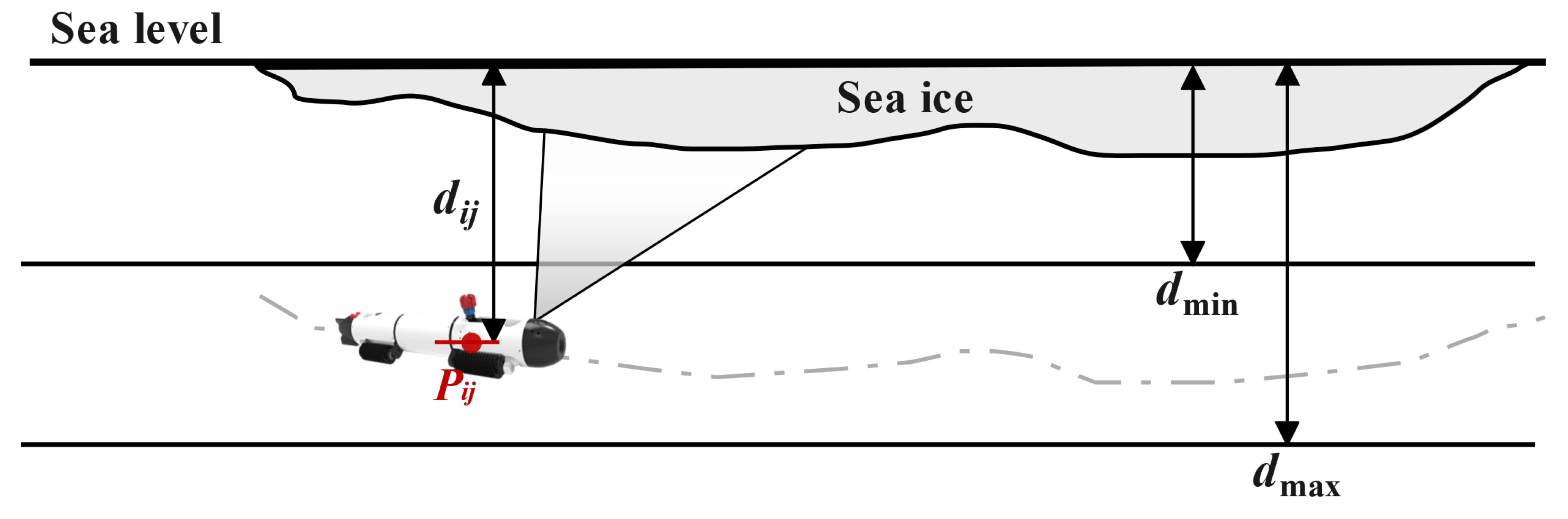
Figure 6.
Azimuth and elevation schematic.
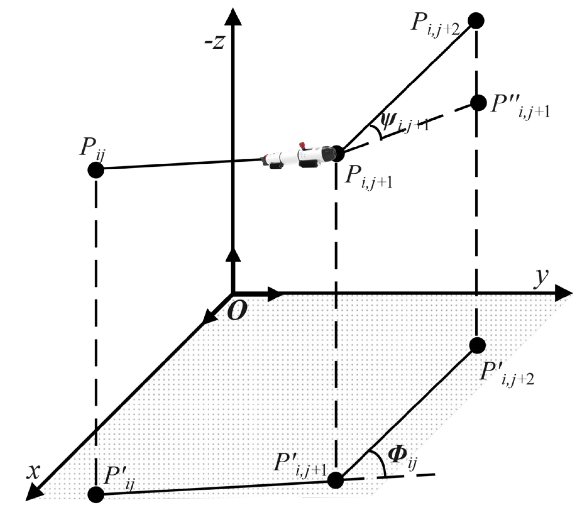
Figure 7.
Ice-breaking cost explanation.
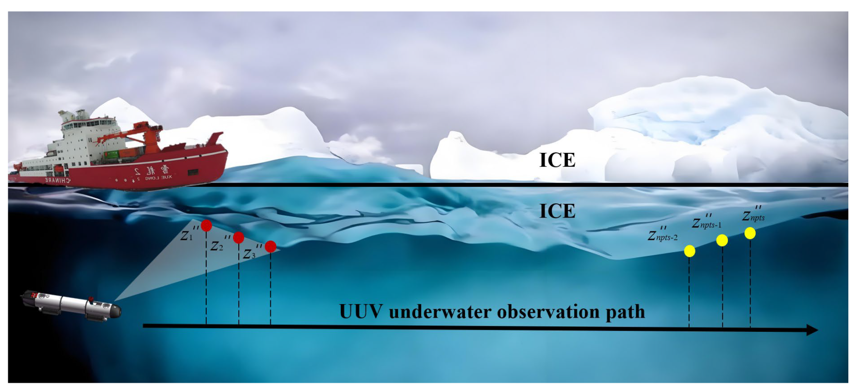
Figure 8.
Implementation of GA-SPSO for path planning.
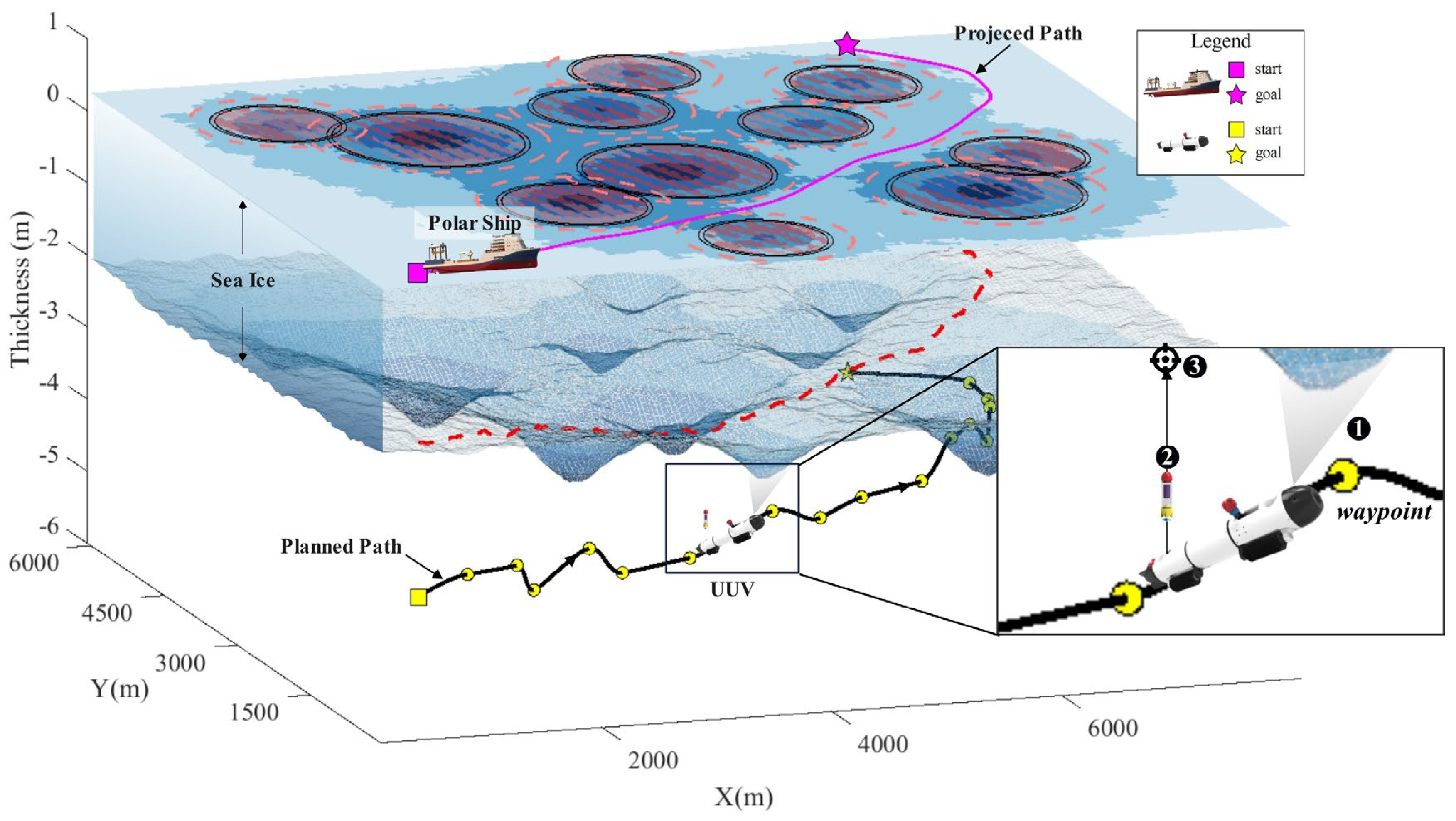
Figure 9.
Comparative effects of two path planning algorithms on icebreaker navigation in three polar ice environment scenarios.
Figure 9.
Comparative effects of two path planning algorithms on icebreaker navigation in three polar ice environment scenarios.
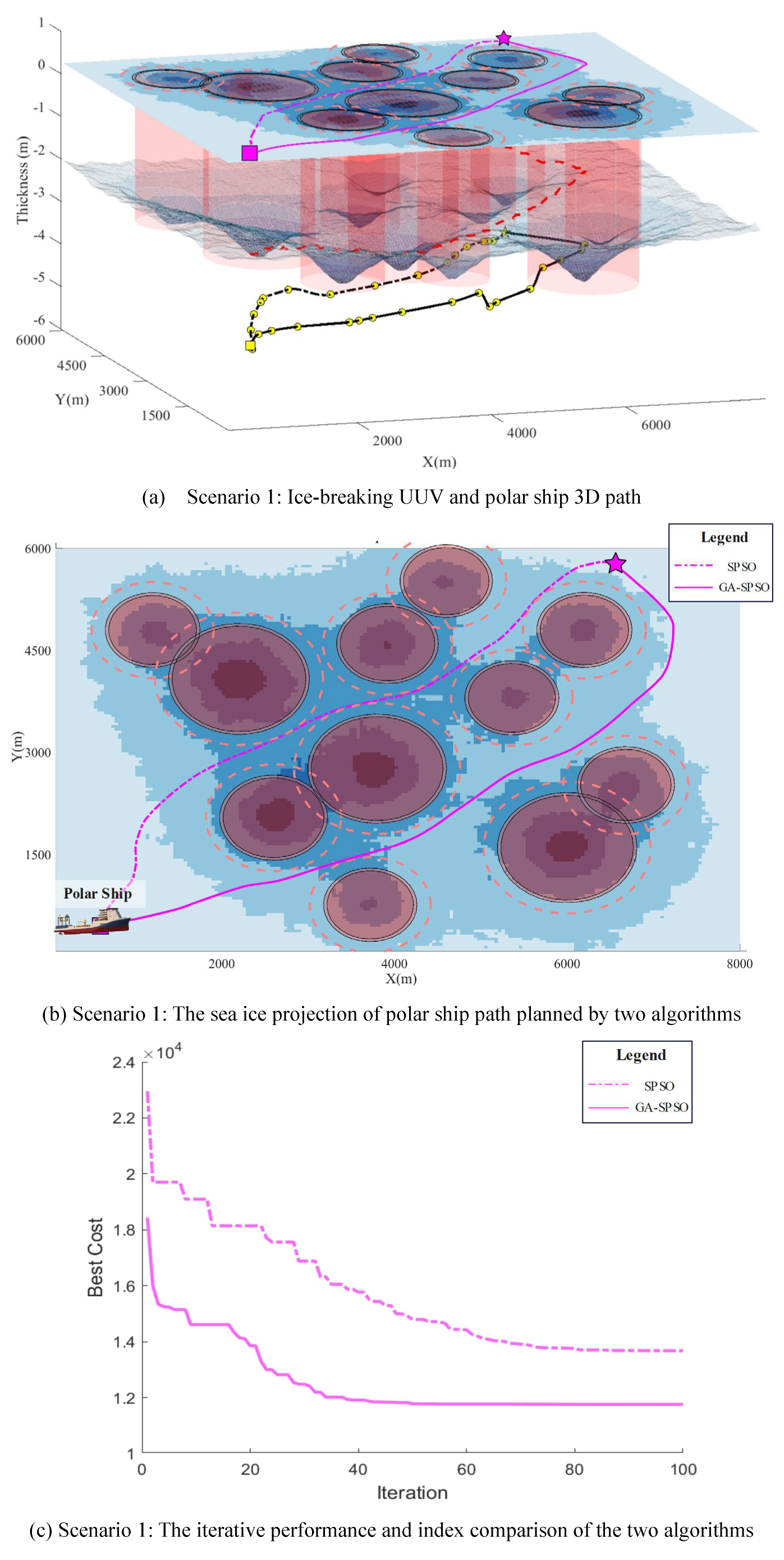
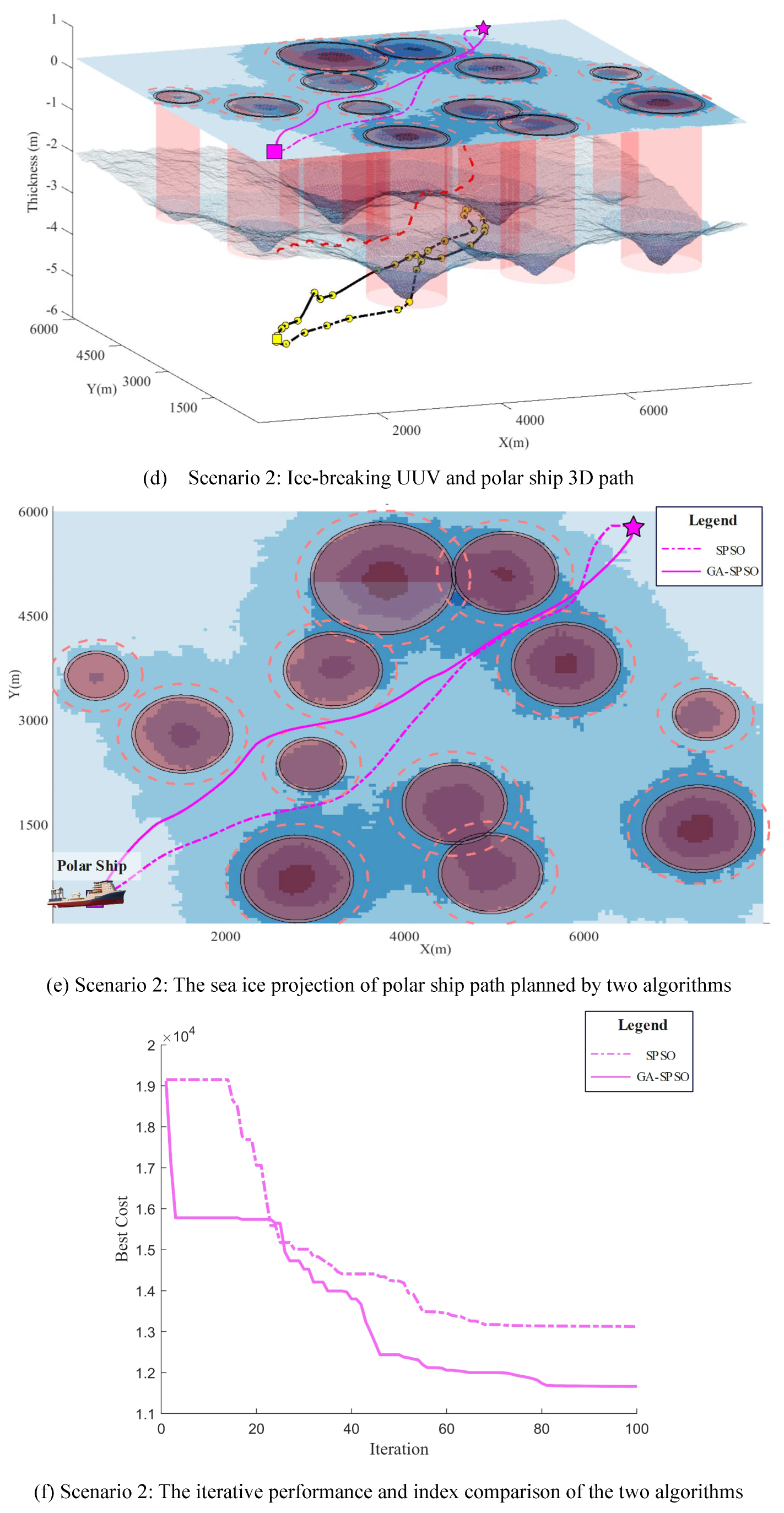
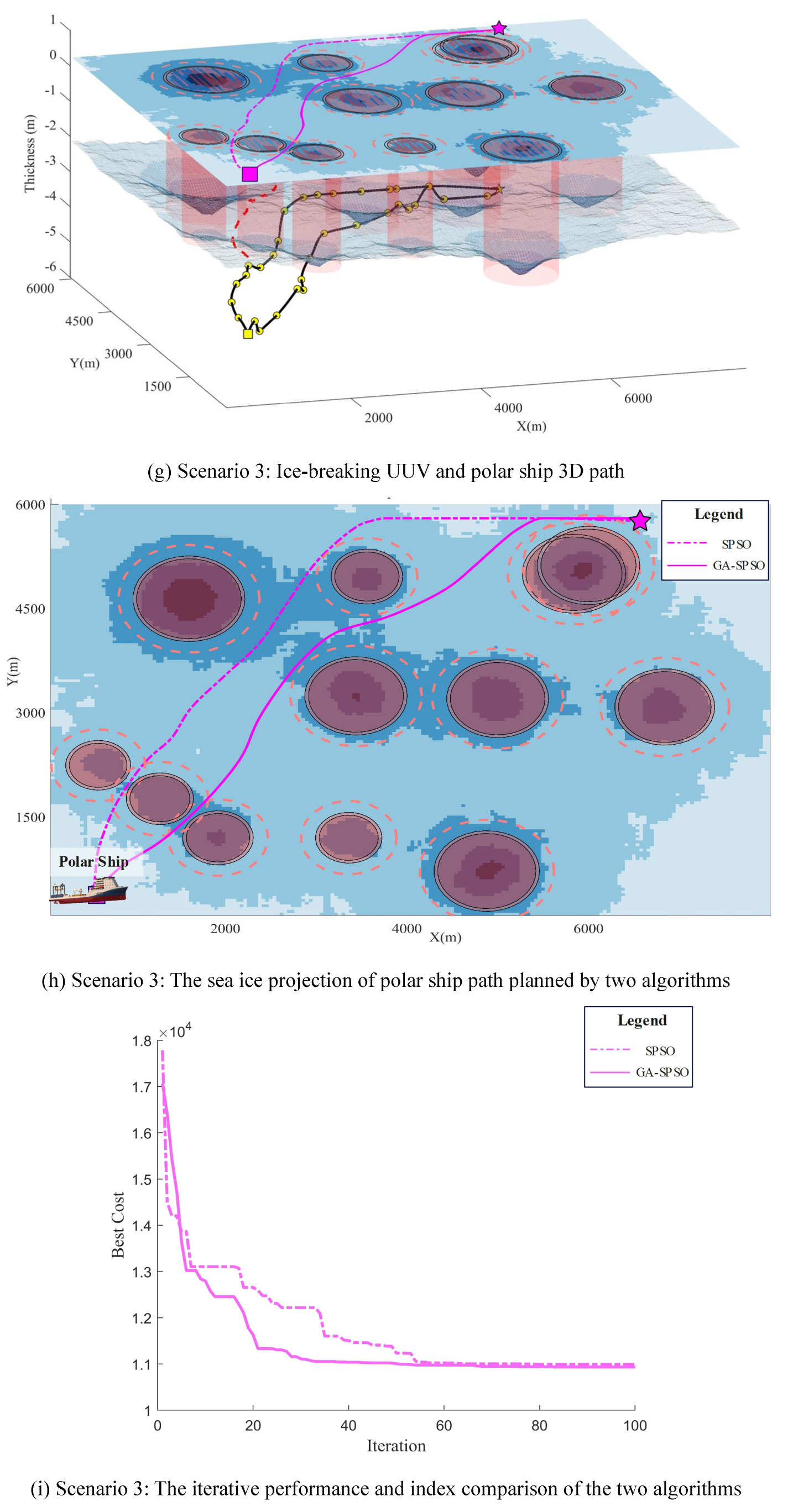

Table 1.
Pseudo code of SPSO for UUV path planning.
| /*Initialization: */ | |
|---|---|
| 1 | Get a search map and initial path planning information; |
|
2 3 |
Set swarm parameters , , , , and ; Initialize , ; |
|
4 5 6 7 8 9 /* 10 11 12 13 |
foreach particle in swarm do | Create a random path | Assign to particle’s position ; | Compute fitness as the local_best of the particle; end Set ; Evolutions by SPSO: */ for 1 to do | foreach particle in swarm do | Compute velocity ; | | Compute new path ; |
|
14 15 16 17 19 20 21 |
| | Map to in Cartesian space; | | Update local_best ; | end| Update global_best when ; | Update ; | Save best_position associated with ; end |
Table 2.
Pseudo code of GA-SPSO for UUV path planning.
| /* Initialization: */ | |
|---|---|
|
1 |
Get a search map and initial path planning information; |
|
2 3 4 |
Set swarm parameters , , , , and ; Set genetic parameters , , and ; Initialize , ; |
|
5 6 7 8 9 10 /* 11 12 13 14 15 16 17 18 |
foreach particle in swarm do | Create a random path | Assign to particle’s position ; | Compute fitness as the local_best of the particle; end Set ; Evolutions by GA-SPSO: */ for 1 to do | Execute selection operation to get the ; | Execute crossover operation on to get ; | Execute mutation operation on ; | Form a new swarm by and ; | foreach particle in swarm do | | Compute velocity ; | | Compute new path ; |
|
19 20 21 22 23 24 25 |
| | Map to in Cartesian space; | | Update local_best ; | End | Update global_best when ; | Update and ; | Save best_position associated with ; end |
Table 3.
GA-SPSO initial parameter definition.
| Categories | Symbol | Value |
|---|---|---|
| maximum number of iteration | 100 | |
| particle population size | 200 | |
| inertia weight | 1 | |
| attenuation factor | 0.98 | |
| learning factors | , | 1.5 |
| waypoints | 16 | |
| selection rate | 0.5 | |
| crossover rate | 0.7 | |
| mutation rate | 0.5 | |
| final mutation rate | 0.1 |
Table 4.
Comparative analysis of algorithms in three different scenarios.
| Scenario | Variable | SPSO | GA-SPSO |
| Scenario 1 | Ice-breaking UUV 3D path | 9194.46 | 9156.09 |
| Polar ship path | 9186.18 | 9148.46 | |
| Iterative performance | 14166.54 | 12061.38 | |
| Rate of convergence | slow | fast | |
| Scenario 2 | Ice-breaking UUV 3D path | 8849.51 | 8258.73 |
| Polar ship path | 8836.61 | 8249.86 | |
| Iterative performance | 13645.98 | 11069.86 | |
| Rate of convergence | slow | fast | |
| Scenario 3 | Ice-breaking UUV 3D path | 9227.74 | 8548.91 |
| Polar ship path | 9218.65 | 8541.77 | |
| Iterative performance | 11023.36 | 9963.74 | |
| Rate of convergence | slow | fast |
Disclaimer/Publisher’s Note: The statements, opinions and data contained in all publications are solely those of the individual author(s) and contributor(s) and not of MDPI and/or the editor(s). MDPI and/or the editor(s) disclaim responsibility for any injury to people or property resulting from any ideas, methods, instructions or products referred to in the content. |
© 2024 by the authors. Licensee MDPI, Basel, Switzerland. This article is an open access article distributed under the terms and conditions of the Creative Commons Attribution (CC BY) license (http://creativecommons.org/licenses/by/4.0/).
Copyright: This open access article is published under a Creative Commons CC BY 4.0 license, which permit the free download, distribution, and reuse, provided that the author and preprint are cited in any reuse.


