
Submitted:
16 August 2024
Posted:
19 August 2024
You are already at the latest version
Abstract
In modern times, technology has become more than just a tool; it is a vital component of our lives, driving society and humanity towards new horizons, better living standards, and solu-tions for complex, global challenges. This article explores the world of dependable systems, specifically focusing on system design, software solutions, and architectural decisions that fa-cilitate collaborative work. It aims to dive into the intricacies of designing robust and effective document collaboration software. Throughout this paper, readers will gain insights into the proposed design process, enabling them to understand, learn from, and critically evaluate the examined methodologies and outcomes. Like everything else in the software technology field, there are multiple solutions to any given problem, and this work is no exception to this rule.
The objective of this study is to provide a detailed architectural overview of the microservices pattern in an orchestrated cloud environment based on independent containers. To examine the pros and cons of such a system, the paper will detail how a real-time document collaboration system can benefit from such an architecture regarding availability, elasticity, scaling, and disaster recovery.
Moreover, the paper will analyze how cloud-native technologies can be used to create a scalable platform solution, capable of handling traffic, dynamic resource storage, asynchronous com-munication, and application scaling. The intricate nature of this system renders this paper a valuable resource for prospective investigations within the domain of dependable systems, cloud computing, and distributed systems.
This paper not only showcases the design and implementation process but also sets a founda-tion for future research and innovation in dependable systems, collaborative technologies, sustainable solutions, and distributed system architecture.
Keywords:
collaborative work
; design document collaboration software
; dependable systems
; microservices pattern
; cloud computing
; orchestrated cloud environment
; independent containers
; collaborative technologies
; distributed system architecture
1. Introduction
In the previous decade, humanity faced one of the greatest periods in its existence in terms of technological evolution in all its forms and fields where is applied.
Software engineering is one of the major pillars of evolution that made possible such a tight linkage between humankind and technology. The estimates were that, at the beginning of the decade, approximately 50 billion devices have access to the Internet [1] and through them, the users utilize digital products and services that help them work, learn, grow, invest, evolve, consume, and communicate with others.
Humans, by their nature, worked collaboratively from the beginning of their existence. In technology, the concept of collaborative work stays the same as in the real world and represents the ability to gather a series of users together to work towards a common goal. This one can be anything from education, investment, and healthcare to industrial engineering or science.
Document collaboration represents such a goal: having a series of users that work together on the same text document in a near-real-time way, just like the process occurs naturally in the physical world. A well-known example of such an implementation is Google Docs [2].
The concept of collaborative work is a core component in other fields that utilize the Internet and various technology solutions to achieve their goal. To name a few: medicine (a series of surgeons using a robot’s controller over the network to perform surgeries [3,4]), construction site machinery operators (technicians working on sites around the world using collaborative technologies [5,6]), various corporate processes (planning tasks, project management, HR [7,8]) and many others.
Regardless of the final goal, all those activities share the same core concept: having a series of individuals working together in near-real time on a common goal. This capability raises a lot of technical challenges that need to be overcome to deliver a stable, available, and scalable user experience. This paper will treat the aspect of availability as critical because the core concept of a collaborative system can be used in applications where failure is not an option. (e.g. the medical field).
This paper intends to comprehensively analyze the design and implementation processes of a microservices-based application in the context of a real-time collaborative text document scenario. Besides the actual application design and implementation, the paper aims to examine the major pillars a modern software system should deliver in terms of availability, scalability, elasticity, and disaster recovery. For the context proposed, those pillars have the following definitions:
Those pillars represent the main quality rules a modern software product should follow. The complex nature of the system was deliberately chosen to provide a high degree of technical complexity and to present a series of architectural challenges that need to be overcome to deliver the application functionality.
This research will focus on these individual critical aspects and implementations:
- Application description and requirements: we’ll examine the overall application features and the functional requirements of the system. We’ll describe some of the functional challenges the system needs to overcome to satisfy the fundamental pillars of modern software development.
- System design: the system design must be capable of delivering the needed functionality showcasing the required building blocks, the reasoning behind the choice, the individual block role and behavior, and the connections to the other parts of the system. We’ll outline the building process of the system architecture, beginning with a simple foundational structure and progressively adding complexity as various technical challenges are introduced.
- Technology background: having a complex end goal, the used technology stack shares the same level of complexity. We’ll investigate the used technologies for each building block, the general infrastructure, and the technology principles used in the design and development of the collaborative system.
- System development: we’ll detail the actual development of the application, covering topics such as conflict resolution, storage handling, application code, services configuration, tooling usage, and microservices interactions.
- Cloud integration: we’ll detail the platform and cloud-native technologies [15] used to move the system from an on-premise infrastructure to the global network of the public cloud providers.
- Architecture validation: we’ll validate the proposed application architecture in terms of scalability, availability, throughput, and resource consumption [16]. Individual components of the system were subject to a series of challenges, disaster scenarios, and tests, to showcase their contribution towards a modern available and scalable application. To further emphasize the validity of the work, performance metrics, and test results were provided.
Given the complexity of the system and the level of detail necessary to comprehensively present all the integration steps, challenges, and benefits, as well as the testing and validation results, this work will primarily focus on analyzing the application features, both functional and technical requirements, the selection of the technology stack, as well as the high-level and low-level system design, along with the challenges encountered throughout the development process.
The migration to the cloud and associated development will be the topic of future research. The focus of that paper will be on migrating individual software components and their dependencies to cloud-native containers, devising a container orchestration management strategy to effectively handle increasing workloads, and highlighting the pillars of well-architected cloud development, such as availability, fault-tolerant storage solution, disaster recovery functionality, operational excellence, and cost-efficiency at scale. Additionally, it will cover container orchestration using Kubernetes within the context of a high-traffic system, the process of migrating to a public cloud environment (specifically Amazon Web Services), integration with third-party services, and, finally, the testing and validation of the benefits associated with transitioning to a cloud-native system.
2. Application Description and Requirements
2.1. Core Entity
A text document, from an engineering point of view, represents a stream of various characters (letters, numbers, symbols) arranged in a specific way by the author. The size of a text document can vary a lot based on the technical implementation and storage limitations.
Besides the actual content, a document may have extra metadata attached to it: title, author information, users that have access to the document, rich text document information, and even other text-encoded resources (e.g. images, charts), etc.
Based on this description, it is possible to identify the core entity of the proposed system: the text document. When it comes to crowd collaboration on a resource, the usage of a system will have a chaotic nature: a small number of users may use a resource, but the number can grow very fast in a short amount of time.
Sharing documents is a common task encountered in many large organizations. There are instances where a resource is shared among all employees, e.g.: sharing a report with an entire department, sending a company-wide attachment, sharing an assignment with a class of students, etc. All those events imply a spike in the number of peers using the entity simultaneously.
2.2. Core Features
It is imperative to develop a system that empowers users to effortlessly create and store text-based documents. Users must have the flexibility to share these documents with peers and to easily manage access rights, including the ability to revoke access if necessary. Collaboration within the system should mimic real-life interactions, enabling one or more users to engage with document content in near real-time.
To ensure a seamless experience, the system should notify users of any changes as they naturally occur in a physical collaboration setting. Furthermore, the system must prioritize safety and security, providing robust measures for handling sensitive data.
To accommodate varying user demands, the system must be scalable and capable of adapting to high usage volumes. All functionalities described should be accessible through a user interface that optimally utilizes real-time collaboration features, enhancing user experience and productivity. As reference numbers, this work aims to have a final product capable of supporting 1000 concurrent user interactions.
To better understand the application requirements, a list of the main system features is provided.
Authentication
Users must be able to create individual accounts seamlessly. These user credentials will be used to create and interact with text documents and other data. Credentials should be securely stored and properly formatted to avoid exposing sensitive information.
Document resource management
Users will have the ability to create, delete, and rename their own documents. Users will also have the option to share the document with other users, based on a unique identifier that can be shared. Moreover, the owner of a text document can restrict access to the resource by revoking the rights to view and interact with the document of specific users.
Document collaboration
Multiple users will have the ability to collaborate in a real-time fashion on a shared resource in a text editing interface where they are aware of each other's contributions. A peer will be able to see the other peer's actions applied in real-time. Example of actions visible to a user in a collaboration session:
- seeing added/deleted characters in a specific part of the document
- seeing the cursor indicator of a user while navigating through the document
- seeing actual logs of all the events received during a session
Notifications
A user should be able to receive real-time push notifications regarding the entities he is linked to. Whenever a user joins a document via an invitation, his access rights are changed by the owner of the document. When the shared document is deleted, the peer should be notified in real time, if possible. If real-time notification delivery is not possible, the notification should be stored for later delivery.
The features deliver a series of various complexity issues and have a diverse range of entities that need to be managed. In the future chapter, the functional requirements will be transformed into technical specifications, and more complex issues and solutions will be examined.
2.3. Performance Metrics
The efficiency of the mentioned system requires quantitative assessment through numerical metrics. Central to the validation of this research are key performance metrics tailored to the outlined scenario, which include:
- Concurrency: the number of users supported at the same time in a collaboration session. Being a matter of resource management and sharing, this metric aims to provide insights about the number of users able to join a session based on the system’s available resources [18].
All these requirements are technically detailed in the next chapters. Working with complex scenarios, all the mentioned features will raise various technical challenges.
3. System Design
3.1. Technical Requirements
Based on the described application functional requirements, a technical solution can be planned, and several technical capabilities can be extracted:
- Users can create accounts and their credentials are stored securely in a persistent manner. With the same credentials, users can authorize actions and interact with the application resources
- In a session, users can create the base document resource and act upon it with CRUD (Create Read Update Delete) operations [19]. All the described operations must be persisted on the final resource. Only the appropriate document owner can interact with the resource at this level.
- Being a real-time application, users should be informed about various events in a near real-time manner (notification system). When a live update is not possible, users should receive the missing updates in an alternative manner.
- The system must provide a real-time document editing experience to all the involved peers. Users should be able to dispatch events resembling the natural interactions a human would do normally on a text resource. The system must handle a considerable number of users simultaneously. As magnitude, the system must be able to support concurrent users in the order of thousands.
- The system must use the appropriate communication technologies to deliver the promised functionality. Data should be delivered in such a way that 95% of the users receive a response in an appropriate time frame with the designated action they executed.
- The persistent solution must provide a robust and reliable storage layer where all the relevant generated user content is going to be stored.
3.2. Application Structure
The described technical and functional requirements require a client-server application. The client-server application pattern [20,21] is the most common way of dividing a complex task into well-segregated components responsible for very specific tasks [22].
This application pattern is composed of:
- Client-side applications: generally, web applications (usually created with technologies like HTML, CSS, and JavaScript) [21,23], mobile applications (created with technologies like Objective-C, Kotlin, Swift, Dart, Flutter, etc.) [24], and desktop applications [25]. This piece of the product aims to deliver a consistent and streamlined experience to the user, handling scenarios like optimum data handling, providing user experience and interactions, animations and transitions, basic client-side security, and low-effort user interface interactions.
The server-side application oversees many other tasks like handling the connections with the data storage solutions, imposing security, and handling architecture and authorization.
In modern development, there is always a constant need for scaling. Systems tend to have a high degree of complexity and generally aim to deliver the promised functionality to a large number of users. To facilitate this behavior, any application needs a proper infrastructure that provides the flexibility and resources required to address a large number of users. This component is generically called cloud infrastructure.
Cloud infrastructure refers to a series of hardware and software tools that a developer can use to provide the processing power needed by an application in a reusable and economical way [28,29]. There are multiple types of cloud infrastructure providers in the industry, ranging from custom cloud solutions developed in-house by companies for their own needs to Global Cloud Providers that offer a range solution of products to individual users and businesses.
With the previously enumerated building blocks, functionality can be divided into two applications: client-side and server-side.
Client-side
The client-side application will handle any aspect linked to a graphical user interface, data input from the user, input validation, providing visual representation for any action that should impact the user, and handling any possible misbehavior of the system.
Server-side
The server-side application will handle features linked to providing an interface usable by the client, handling data storage and manipulation, handling document editing logic, provide security/integrity checks on all the used resources.
3.3. System Organization
Most of the functionality of the system will rely on the server implementation while the client will act mostly as a presentation layer for the end-user. Both sides of the system can be delivered in multiple ways. The next decision to make is how the entities should be organized. Such a system can be delivered using two main ways:
- Monolithic
- Distributed microservices
A monolithic system usually represents a system where all the building blocks are delivered under the same process [30,31]. From a development point of view, it is the easiest way to build and deliver software since all the resources are accessible by all the application blocks. To evaluate if a monolithic architecture is the proper solution for collaborative document editing software, there are two fundamental questions to be addressed: What are the scaling needs of the system? and What are the scaling capabilities of the architecture?
3.4. Scaling
The system might need to serve a considerable number of users but this must not be confused with the actual needed functionality at scale. Undoubtedly, certain functionalities do not need the same amount of scaling capabilities. Features like login/register won’t be as largely used as the actual document read/write operations. With these simple details, we can answer the first question: The system needs some parts of it to be more suitable for scaling than others.
To answer the second question, we need to properly evaluate how system scaling works. Scaling, in simple terms, means the process of allocating more resources to better handle a task. Scaling can be of two types [32]:
- Vertical: where more hardware resources are provided to keep up with the load.
- Horizontal: where more instances of the running process are provided to split the work among other workers.
Vertical scaling is more expensive because it implies hardware changes. Moreover, it also imposes downtime since the system must be physically upgraded. Another drawback of vertical scaling is the price and hardware limitation.
Horizontal scaling is more complex to achieve based on the tooling, it raises a series of issues on its own in terms of application architecture, but in the end, is the most efficient way of scaling for our system.
3.5. Microservices
Scaling the system as an individual process is not particularly necessary, since it is possible to isolate and scale the functionality. This pattern is known as microservices and implies dividing a single application into multiple smaller stand-alone individual applications that communicate with each other over the network [30,31]. This type of architecture has several benefits:
- Scalability: Independent services can be scaled individually, optimizing resource allocation.
- Flexibility: Enables faster development and deployment cycles with each service developed, deployed, and scaled independently.
- Fault isolation: Failures in one microservice instance do not affect the entire system, enhancing reliability.
- Technology diversity: Allows the use of different technologies for different services, optimizing for specific needs.
- Easy maintenance: Easier to maintain and update as changes to one service do not necessarily impact others.
- Continuous delivery and integration: Supports continuous integration and delivery practices, facilitating a more streamlined development process.
- Resilience: Improved fault tolerance and resilience due to the distributed nature of services.
- Autonomy: Teams can work independently on different services, fostering autonomy and speeding up development.
- Better resource utilization: Efficient use of resources as each microservice can be optimized for its specific task.
The microservices pattern is more suitable because it allows independent scaling and control over the pieces of functionality that produce higher traffic and computing overhead [33]. As an organization rule, the overall server-side functionality will be divided into multiple independent smaller and self-contained services. Each application will expose a specific set of functionalities (API – Application Programming Interface – a series of exposed calls to the system).
Based on the known requirements, we can identify the following microservices:
- Documents API: a module for handling the actual document creation and basic manipulation of all the resources besides the document content.
- Document Manipulation API: an API designated for handling collaboration sessions in real-time between the users and responsible for storing the data generated in the sessions.
- Notifications API: the application will have a channel for delivering notifications to users in real-time mode whenever possible and offline capabilities for storage and late-delivery.
Any system requires a series of utility modules/microservices. Certain functionalities will naturally require child services that will solve very specific tasks. For example: the real-time document manipulation API will handle document content editing. Serving a considerable number of peers over the network imposes another challenge: supporting multiple consumers.
To respect the microservices pattern, complex or specific pieces of work should be delegated to individual microservices for better scaling and reusability. By this rule, a real-time client communication API can be introduced. This module will be dedicated to handling the open connections between the server and clients. This microservice will serve to produce events based on user interaction.
Naturally, when having a series of smaller self-container applications that need to work together to achieve a final goal, a question occurs: How will a client interact with those applications? In such instances, where a client needs to interact with various external services, the easiest approach is to introduce a single point of entry. It presents the following advantages:
- The client implementation doesn’t need to know about the specifics of the services providing the functionality. A single point of entry can “hide” all the building blocks from the client and provide only what is necessary.
- A single point of entry facilitates global operations like monitoring, logging, authorization, etc.
- Provides routing to the needed functionality.
3.6. Cross-Service Communications
In the distributed system world, the individual building blocks will need to communicate with each other. Microservices can establish two types of communication channels:
- Synchronous communication between services refers to a communication pattern when a service sends a request and waits for the response before continuing its execution.
- Asynchronous communication between services is a pattern where a service sends a message or request without waiting for an immediate response. In contrast to synchronous communication, which involves a request and an immediate waiting period for a response, asynchronous communication allows services to operate independently and asynchronously process messages over time.
Event-driven architecture (EDA) (Figure 2) is a design paradigm where systems respond to and communicate through events, allowing for real-time responsiveness and flexibility [35]. Events representing meaningful occurrences, trigger actions in a decoupled manner, enhancing scalability and modularity. Synchronous communication in EDA involves immediate and direct interactions between components, where a sender expects an immediate response from a receiver.
There are multiple software implementations available in the field for implementing an EDA. Most of them gravitate around the idea of message queues.
The EDA has also a major drawback: it requires a change of paradigm in terms of how the actual application code is designed to run. The synergy of event-driven architecture and synchronous communication addresses diverse requirements, offering a versatile solution for dynamic and responsive systems in various technological landscapes.
3.7. Client-Server Communication
The inner communication between the microservices is not the only important communication channel. Having a client-server application, it is important to choose the appropriate communication methodologies for client interaction. In a client-server architecture, it is quite common to use a synchronous protocol for data transfer such as HTTP, and the REST architecture. REST (Representational State Transfer) is an architectural style for network applications [36]. It uses the HTTP methods (GET, POST, PUT, DELETE) for communication, emphasizing simplicity, scalability, and statelessness.
The asynchronous communication can be further detailed based on the direction of communication:
- full-duplex – used for bidirectional client-server communication. This type of communication channel is more expensive in comparison with the HTTP protocol but also provides more flexibility for live data streaming. The protocol of choice for this communication type is WebSocket [37]. The protocol provides a persistent, bidirectional communication channel over a single, long-lived connection between a client and server. This enables real-time, low-latency data exchange, making it suitable for interactive applications. Unlike traditional HTTP, WebSocket facilitates full-duplex communication, allowing both sides to send messages independently. The WebSocket protocol operates over the standard ports 80 (HTTP) and 443 (HTTPS) and is supported by most modern web browsers, servers, and frameworks, fostering efficient, real-time communication in web applications.
- half duplex – used for unidirectional data streaming. This type of communication can be achieved using SSE (Server Sent Events). It’s a web technology that enables servers to push real-time updates to web clients over a single HTTP connection [38].
Unlike traditional request-response models, SSE establishes a long-lived connection, allowing servers to send periodic updates to clients (Figure 3). This type of communication is particularly useful for applications requiring real-time data, such as live feeds, notifications, or financial market updates, without the need for constant client polling.
The application diagram is updated so that the messaging layer is now introduced (Figure 4).
The system requires a storage layer for persisting various data entities the application is handling: user accounts, document metadata, document content, and notifications. In the microservices pattern, a microservice is tied to its own data source to maintain the integrity and the self-contained attribute of the architecture. The architecture diagram of the system can be extended with the representation of the storage levels (Figure 5).
4. Technologies Stack
This section will provide a comprehensive overview of all major technologies used for each building block of the collaborative system design. No software technology is perfect; all major software products have certain drawbacks, and the selected technology stack for this system is no exception. This chapter is designed as a linear roadmap, starting with the initial technologies used, discussing the drawbacks encountered, and continuing with the additional tools, technologies, or implementations required to overcome these issues.
Going from the client to the server, we encounter the following layers:
4.1. Client-Side
Vue.js is a JavaScript framework for user interfaces. With a declarative syntax, it enables the creation of dynamic and responsive applications [39]. Vue.js's component-based architecture promotes code reuse and maintainability. Its reactivity system ensures automatic UI updates when data changes.
The client, in this case, the user browser, will be responsible for running its own code, thus making a clear separation from the server side. It is possible to make the client-side application part of the server but for the sake of scaling and decoupling this practice was discouraged for this research. The client will consist of a Single Page Application (SPA) Vue.js that will provide all the required forms and user-interface components the user will need to collaborate on a text document.
4.2. Server-Side
One advantage of the microservices architecture is the flexibility it offers. Each microservice can be developed using various technologies to accommodate different development teams or to reuse microservices from other applications. For consistency, all the microservices of the system were developed with the Spring Boot framework [40] backed by the Java programming language [41].
Java features automatic memory management, strong type-checking, and a vast ecosystem of libraries. The Java programming language is an industry-standard when it comes to API and server-side application development [42]. A very popular library used for the implementation of the microservices described previously is Spring Boot.
Spring Boot is an open-source framework designed to simplify the development of Java applications. It streamlines the setup and configuration, promoting convention over configuration. With embedded servers, it eliminates the need for external deployment. Spring Boot provides a rich set of pre-built components for common tasks, enabling rapid development and reducing boilerplate code. Its modularity allows developers to choose only the required features, enhancing efficiency.
4.3. Infrastructure
Having the client-side and server-side application code is not enough to maintain a system, especially when scaling and handling considerable user traffic. While it is important to have performant and highly available application code, it is crucial to have the necessary architecture to support and manage that code.
In real-world applications, especially in microservices architecture, individual system components can fail, data storage solutions can be compromised, and systems may experience downtime for maintenance and reconfiguration. Managing these issues manually can be highly challenging and becomes impossible when scaling to support hundreds of users. Therefore, an automatic and declarative approach is necessary for system administration. Several tools can manage application failures, scaling, restarting, and initialization to ensure system reliability. In this research, Kubernetes was selected for these tasks.
Kubernetes
Kubernetes (often abbreviated as K8s) is the leading open-source platform for container orchestration, allowing organizations to efficiently manage and deploy containerized applications at scale [43]. Kubernetes abstracts the underlying infrastructure, providing a unified API for managing diverse workloads. It enables seamless scaling, rolling updates, and efficient resource allocation, ensuring high availability and fault tolerance. Kubernetes simplifies the complexities of containerized deployments, fostering portability across diverse environments.
With features like declarative configuration and service discovery, Kubernetes has become the cornerstone of modern, scalable, and resilient container-based application architectures. K8s is responsible for handling in a cluster the running applications (called Pods), as presented in Figure 6, by following a series of user-defined rules:
- how a certain application should be executed
- how many running instances should an application have
- what should happen when an application instance is subject to increased or decreased user demand
The central orchestrated resource is called Pod and represents a running instance of an application inside the cluster. Kubernetes can handle far more complex infrastructure setups, including handling environment variables, storing and delivering keys, tokens, and secret keys, and interacting with the Cloud Infrastructure for handling hardware or other software services.
Kubernetes requires an agnostic way of running application code because the platform is not designed to provide the required software dependencies (e.g. runtimes or Standard Development Kits). Kubernetes is designed to run containerized applications. Containers-based development represents the pattern of encapsulating the application code and the required execution dependencies in a single executable that can be deployed on any Operating System without the need to configure anything besides the container runtime. By default, K8s uses Docker for executing the application containers.
Docker
Docker is an open-source platform that facilitates the development, deployment, and scaling of applications by using containerization [44]. Containers encapsulate an application and its dependencies into a single, lightweight unit, ensuring consistency across different environments. The Docker platform provides a standardized approach to packaging applications, allowing developers to create, share, and deploy applications seamlessly across diverse computing environments.
Docker works by utilizing containerization to package applications and their dependencies into isolated units called containers. These containers encapsulate the entire runtime environment, ensuring consistency across different systems. Docker's client-server architecture enables users to build, share, and deploy applications seamlessly. Docker and virtual machines (VMs) differ in their virtualization approaches. Docker uses containerization, sharing the host OS kernel for lightweight, portable, and efficient application deployment.
Containers offer fast startup times and process-level isolation. In contrast, VMs rely on hypervisor-based virtualization, creating complete OS instances with higher resource overhead. VMs provide stronger isolation but are heavier and less portable due to separate OS instances. Docker emphasizes agility and efficiency, ideal for microservices, while VMs prioritize stronger isolation and are suited for scenarios requiring complete OS independence and security [45]. The choice depends on specific use cases and performance requirements. At this point, the initial architectural overview of the system will suffer a design change: all the microservices code will be wrapped in individual Docker containers and handled by Kubernetes.
GraalVM
Regardless of its popularity, Spring Boot has a series of drawbacks that could affect the performance of a real-time document collaboration system [46]. Spring Boot by default runs a series of tasks before starting an application, e.g.:
- Auto-Configuration: Spring Boot scans the classpath for libraries and automatically configures beans based on the detected dependencies. This can lead to longer startup times, especially in large applications with numerous dependencies.
- Annotation Processing: Spring Boot heavily relies on annotations for configuration. The process of scanning and processing annotations can contribute to increased startup times, particularly in applications with extensive use of annotations.
- Reflection: Spring Boot uses reflection to dynamically inspect and instantiate classes. This introspection can impact startup performance, especially in applications with deep class hierarchies [47].
- Initialization Overhead: Spring Boot applications may have initialization overhead as they set up various components, such as the Spring Application Context, which contributes to the overall startup time.
In the context of a real-time document collaboration application, due to the nature of the system, high spikes of traffic are expected. Waiting for a few seconds before a new microservice instance is up and running can affect the availability of the system. Part of the problem is the way Spring Boot is handled through the Java Virtual Machine (JVM).
To speed up the start-up process of a microservice, the decision was to switch the compilation target from Java artifacts to native binaries. Native binaries represent a more resource-efficient compilation target that does not require the presence of a runtime environment to be executed. Compiling a Spring Boot application to native binaries can be achieved with GraalVM [45].
GraalVM is a high-performance runtime that provides support for various programming languages and execution modes. Developed by Oracle Labs, GraalVM is designed to improve the performance and interoperability of applications. Regarding the performance boost, GraalVM offers significantly lower (even up to 90%) start-up times of Spring Boot applications and lower CPU and memory consumption.
Inter-service communication – Apache Kafka
By now, the described system design offered a detailed overview of the communication layers available in the cluster. There is an obvious need for a decoupled asynchronous messaging service simply because the core functionality can’t be provided in a near-real-time fashion using blocking or synchronous communication methods.
To supply this need, Apache Kafka was used as a messaging service. Apache Kafka is a messaging system that allows scaling and distribution of work to facilitate the flow of data from producers to consumers. Essentially, Kafka is a very sophisticated and distributed queue-like structure where messages are pushed [46].
There are a series of functionalities that will generate events that need to travel in a near real-time fashion between the client and the service. It is common for microservices to interact with one another. In the designed system, the document content manipulation API might produce an event that needs to be transported toward the client via a real-time child service [48]. Kafka can facilitate this low-latency communication [49].
Besides the fast processing of data, Kafka has another major advantage: its distributed nature. The messaging service can run on multiple systems over the network thus being able to deliver messages even when one or more systems go offline.
Storage
Storage is the backbone of every software system that generates data. The proposed system design contains various entities that must be stored to provide a continuously available system:
- User accounts
- Notifications data
- Document content and metadata
In a microservices architecture, it is recommended that the databases be segregated into multiple, smaller, and independent databases to serve only one function. This approach simplifies the structure of data but creates other problems
By dividing the application data schema into smaller independent applications, the possible relationships between data are impossible to maintain at the database level. Those constraints need to be maintained at runtime with application code. The advantage of this pattern is the diversity of options in terms of storage solutions. In some cases, a relational model might be necessary, while in other use cases, a non-relational model might provide more flexibility. In this system, two main storage solutions were used: MongoDB and PostgreSQL.
MongoDB
MongoDB is a highly flexible and scalable NoSQL database. It stores data in flexible, JSON-like BSON documents, allowing for dynamic schema design [50]. MongoDB's powerful querying and indexing capabilities make it suitable for diverse applications, ranging from small projects to large-scale, data-intensive solutions [51].
This database storage solution is suitable for an entity that might suffer multiple changes in its structure and require a higher degree of flexibility [52]. The actual document content storage will benefit from the higher degree of flexibility because the schema of a document content may contain big amounts of data in a tree-like structure that’s more suitable for resembling the structure of the document the user will need to visualize. The flexible format also benefits the integration of additional metadata that a rich text-document might use: definition of specific text color/highlight in the document, in-line styles (bold, italic), and different font-family text sections. All those examples can be reduced to a simple map-like structure where the keys define the text selection position, and the values define the metadata applied to that text selection.
With a traditional relational model, maintaining a big entity over multiple tables can create bottlenecks in terms of read/write speeds.
PostgreSQL
PostgreSQL is an open-source relational database system. Known for its reliability and extensibility, it supports complex queries, indexing, and transactions. PostgreSQL adheres to SQL standards and provides advanced features like JSON support, full-text search, and spatial data capabilities [53].
This database storage solution was used for entities that do not require a flexible data format: notifications, users, and basic document information [54]. Those entities might suffer fewer migrations in terms of their data structures because their intended use does not require schema transformations as in the case of document content storage. Most of the resources stored in a standard relational database are primarily used as look-up tables for checking data constraints (e.g., if a user has access to a document, retrieving all read notifications, getting the base document title, creation date, or shared users). In the few instances when a record gets updated (e.g., a document title update, a last-edit timestamp update, a user is added as a shared collaborator to a document, a notification is marked as read), the structure of the data model does not change, so no flexibility of the data is required. Relational database indexes can be used to facilitate faster data retrieval without adding another complexity layer, such as a caching system [E2].
As already emphasized, the technology stack is as complex as the application requirements. This chapter offered a brief description of the needed technologies to solve the main challenges of the project. Each step invested in the development of the proposed application raised a significant number of challenges that are going to be detailed as the actual development is presented.
5. System Development
This chapter will examine the microservices interfaces and the functionality they expose, the Kafka setup and the necessary event-driven architecture setup, the algorithm used to process the concurrent document editing events, and server bridging to distribute the workload. We’ll also investigate the scaling process and the technical challenges encountered in the process.
5.1. Apache Kafka Application Setup
Kafka is an essential part of the document collaboration system. It powers the communication between the microservices and helps in a series of scalability aspects.
[E1] As previously stated, designing event-driven architectures involves a series of changes in how software components are planned and implemented. Applications utilizing such architectures are susceptible to inconsistent workloads. Therefore, it is important to:
- -
- Design components to be as stateless as possible. The software components of a system should serve their purpose without needing an initial setup or pre-preparation of data (e.g., loading information from look-up tables, or building an in-memory cache). Workloads are ephemeral, and the components of a system should be able to be added or removed elastically without producing any side effects.
- -
- Build with redundancy in mind. A system is only as strong as its weakest component. Each core feature should be highly available, meaning that all business logic can't be delegated to a single instance of a worker. Core functionality should have backup instances that can handle additional load or replace an unhealthy worker instance.
- -
- Create reactive workflows. In high-traffic applications, especially in real-time systems, every millisecond of delay can impact the outcome of an operation. Communication between software components must be done asynchronously whenever possible. Software components must be able to listen to a common stream of events and react whenever work is delegated. When a result is available, it should be queued in a stream and distributed among the available workers, thus avoiding bottlenecks and the creation of a single-point of failure.
Kafka initial setup
In simpler terms, Apache Kafka represents a queue structure into which producers (in this case users or other microservices) can push events. Consumers will subscribe to the stream of data and react to the received events (Figure 7).
The messages are consumed in the order they are emitted in the queue. Having a single queue structure can drastically impact the availability of the system because it creates a single point of failure. Apache Kafka can be configured to run multiple queues distributed across a network, even across multiple running servers (Figure 8). In this setup, if a messaging stream becomes unavailable, the other queues can pick up and distribute the data. Kafka can set up a distribution strategy on how the streamed events are linked to consumers.
Kafka topics
Usually, the queues are distributed among multiple servers called partitions. Partitions are responsible for the distribution of events, also called records. “Apache Kafka uses partitions to scale a topic across many brokers for producers to write data in parallel, and to further enable parallel reading of consumers. Every partition can be replicated across the Apache Kafka brokers for purposes of fault tolerance.” [55]
In the document collaboration system, a specific action in a microservice might need to trigger an event in another microservice via the Kafka stream (e.g. a document deletion should inform the shared users about the missing access to the resource.). The scenarios where the events can be grouped by purpose are called topics. The document editing topic may contain events such as title updates, content updates, style changes, user invites, etc.
Based on the same idea, other topics specific to the described system could be extracted (Figure 9):
Consumer Complexity at Scale
In the System Design chapter, horizontal scaling was nominated as the preferred solution for scaling parts of the application features. Kafka provides powerful configurations in terms of consumption strategy by utilizing consumer groups. It is ideal to keep each microservice as simple as possible and as stateless as possible.
Stateless microservices are small software applications that process an input to obtain a desired output without needing to store the state in their internal memory. This design choice has its source in the horizontal scaling approach where multiple instances of an application are running at the same time and share a bigger load of work.
Consumer Grouping
Apache Kafka offers a specific way of delivering messages to consumers. A consumer represents an application instance that subscribes to a Kafka topic to receive messages. Upon subscribing, the consumer will be assigned to a consumer group, indicated at runtime as a consumer group identifier. Multiple consumers can have the same consumer group ID, thus creating a consumer group. In this case, when a message is emitted on a topic, only the first available consumer in that group will receive the message (Figure 10).
If consumer C1 becomes unavailable, the other consumers are going to pick up the incoming messages because they are part of the same consumer group. This behavior is used in places where multiple backup running instances for a microservice exist. If multiple instances are required to run in parallel, multiple partitions will be required. Each partition can be thought of as a separate "stream" of messages within the same topic.
In the proposed application setup, there are instances where all the consumers need to receive the same message (broadcasting information to all subscribers). To achieve that behavior, each consumer needs to be assigned to a different consumer group (Figure 11).
In the context of the real-time document collaboration system, Apache Kafka was used as a message broker to distribute events across the microservices. Besides distributing messages, Kafka was also used for grouping microservices as follows:
Consumer groups: In this setup, multiple document content manipulation instances were grouped to provide a highly available set of workers ready to handle incoming editing messages from subscribed clients. This broadcasting strategy ensures that there is always a microservice instance ready to intercept a message from the Kafka stream.
Broadcasting groups: For the RTC (Real-Time Collaboration) microservices, it is crucial that each instance receives the broadcasted document editing messages emitted by a user. This ensures that all subscribed users can receive updates regarding a document. A consumer group allows only one instance to consume a message at a time. By creating multiple consumer groups, each with a uniquely identifiable consumer, it can be guaranteed that all subscribers will receive a message. The downside of this approach is the higher resource consumption of the Kafka cluster [E3].
5.2. Microservices Interface
Each microservice exposes a REST API interface to the outside world, focuses on a single well-defined purpose, and contains its own data layer which is not shared with any other application service. Moreover, the microservices are responsible for maintaining their own data relationship rules and integrity checks. We’ll investigate the working principle of each microservice.
Auth
This microservice exposes a series of POST methods for user authentication (/login and /register) and user authorization (/check-token).
JavaScript Web (JWT) tokens are a common pattern used for providing stateless authorization based on a cryptographic token attached to each request. When the server detects a valid token attached to a request that needs an authorization check, it will serve that request. Otherwise, it will block any further interaction.
A JWT token (Figure 12) is generated with the help of a one-way hash cryptographic function like SHA256 that uses a secret key to sign the token and an expiration date to invalidate it in the future. A JWT includes three parts: a header, a payload, and a signature. The header typically specifies the type of the token and the signing algorithm.
The payload contains claims or statements about the subject, and the signature is created using a secret key, ensuring the integrity of the token. Together, these components form a base64-encoded string that can be used for secure information exchange and authentication between parties. The main benefit of JWT is the stateless approach. The security of the system relies on the cryptographic nature of the encoded information. Being stateless simplifies the application code needed to maintain the microservice because no records about the user auth state need to be maintained.
Auth microservice has access only to the user’s database and all the traffic to other domains records from the network is blocked. Exposing only the needed inputs and outputs is a common practice in microservices development ensuring the traffic flowing in the appropriate direction.
Notifications
This microservice exposes the following functionality:
- /subscribe – The user will subscribe to an events stream to receive notifications in real-time while the user has active sessions.
- /unread - API endpoint for receiving notifications stored while the user was offline.
- /read-all – API endpoint for marking all the notifications as “read”.
- /read – API endpoint for receiving the older notifications.
As previously mentioned, there are multiple places from where a notification can be triggered. The notification microservice holds a live subscription to the notification’s topic. Besides delivering notifications, it will also store the logs of the delivered/not-delivered notifications in persistence storage.
Document Manipulation
This API provides basic manipulation capabilities for the document entity like:
- Creating the actual document
- Getting user-owned and shared documents
- Getting individual document details
- Deleting a document
- Adding a user as a shared user to the document access list
- Removing a user as a shared user
The decision to split the document metadata from the actual document content was made based on the scaling needs of the two functionalities. The basic CRUD actions done on the document entity will be less frequent than the updates done on the content level. Thus, better usage of a resource can be achieved since the manipulation API won’t need as many running instances as the content API.
Document Content
This microservice will handle the update operations and organization of the actual document content in a work session between users. This microservice will receive update events from the users and will handle them accordingly alongside the saving strategy imposed on the document content. The algorithm powering the collaboration work and decision-making will be discussed in its own section.
RTC
As previously discussed, the document editing sessions will be handled over a WebSocket connection based on the need for a direct asynchronous connection. The number of live established connections may be considered a sensitive point in the architecture of the system, as any server has a physical limit on live connections. Thus, due to scalability concerns, a designated microservice for handling live connections was created.
The RTC (Real Time Communications) microservice is responsible for handling the connections with the clients and propagating changes between the RTC instances.
Having a horizontal scaling approach on live-maintained connections introduces the problem of unpredictable connection location. This scaling issue is described in its own section due to the increased complexity and required messaging service modifications.
If the client-server connection fails, the server cannot re-initiate it. The task of reconnecting and synchronizing must be initiated by the client.
API Gateway
The API Gateway is the last building block of the system interface for the client, and it serves three main purposes in this setup:
- provide routing to the designated microservice of a request
- provide a security layer with the help of the Auth microservice
- provide CORS protection
Cross-Origin Resource Sharing (CORS) is a security feature for web browsers. It permits or restricts web applications running at one origin (domain) to request resources from a different origin, mitigating potential security risks associated with cross-origin HTTP requests.
The API Gateway integrates the security measures using the Spring Security package for adding the necessary JWT token checks upon a private route request. The Gateway relies on a Security Filter Bean to ensure that the appropriate JWT token metadata exists and that it is valid. If an invalid request is intercepted, the gateway will isolate the request and return the appropriate error code for the client to handle. If a request has a valid token, the API Gateway will validate the token with the help of the Auth microservice and extract the data contained in the JWT token.
The JWT payload will be attached to the original request before routing it back to the appropriate microservice. In this case, basic information about the user (id, email, nickname) was attached to the request with the help of HTTP Headers. This step will save further database reads at the microservice layer for retrieving user data.
If the databases are segregated between multiple microservices, no relationship between data can be maintained. The main reason behind this drawback is the fact that the databases can be physically distributed across nodes and thus maintaining relationships between entities cannot be achieved. The constraints between entities are moved to the application layer and the integrity of data must be maintained with the help of application business logic. In most implementations, there is a constant need to interrogate databases or check resource permissions based on user credentials. Fetching the user resources at every action can potentially induce bottlenecks in terms of performance.
Besides the CORS and Authorization state checks, the API Gateway layer handles application routing. To define the routing strategy, the API Gateway will require two main pieces of information: the prefix of the incoming request and the destination address to which the service should be redirected.
5.3. CRDT
Document collaboration is a complex task because it imposes challenges such as ensuring document consistency and conflict resolution, handling read/write intensive tasks in a low latency environment, and multi-peer data transfer between clients in a low latency way. Those issues are a big concern in terms of functionality and are isolated from the problem of the system architecture that can sustain such an application at scale.
Initial Analysis
Let’s consider a series of users accessing the same text resource. Each user can apply locally one of the following basic operations:
Insertion: The user can insert a character at a given position. The operation will be denoted INSERT(C, Index) where C represents the inserted character and Index is the position where it was inserted. The state of the string will be denoted with S.
S = Test. INSERT(’I’, 4) → TestI
Deletion: A user can delete the character on a specific position. The operation will be denoted as DELETE(Index) where Index represents the removed position.
S = Test. DELETE(0) → est
Every other classic text manipulation operation (group delete, group insertion, etc.) can be reduced to either a delete or insert operation applied to a range (individual characters selected) or a selection of indexes (a sequential block of text selected).
S = Test. REPLACE(0, ‘A’) → DELETE(0) -> INSERT(‘A’, 0) -> Aest
Starting from the same resource, users will apply a series of insertion/deletion operations that will modify the shared resource. Each change made by a user needs to be broadcast to all the users that participate in the collaboration session. There is a chance that users can introduce different changes at the same index.
Figure 13 demonstrates a scenario where two users apply changes to the same resource and, due to the nature of the changes, they obtain different states of the same resource. The system will not converge to a single result in certain scenarios, which is a fundamental requirement for a collaborative system design.
The problem of convergence can be handled on either the client side or on the server side.
Server-side Conflict Resolution
In this case, the server will be the authority (also called the leader) to decide how the conflicts are resolved, thus the server-side application running the code that handles the document changes needs to be stateful. This is a major issue for a dependable system since it requires a way to handle the application state in case of a system disaster. It also makes the server side a key component for the minimum functionality of the system.
All the clients need to talk directly to the specific server that holds the state of the document, creating a problem in terms of scalability and cloud agnosticism (Figure 14).
The server application needs to have an in-memory state and custom application logic that needs to be continuously saved and restored in the case of a disaster. The operation consumption and server-side processing may affect the availability of the system in big collaboration groups where multiple changes could be applied in a short time. Since the server obtains from the client only the operations that the user generates, it must deal with and adapt the operations to converge the state of each user.
For example, when a user deletes from a position where previously a character was inserted, the deletion index needs to be updated to delete the initial designated value.
S =”Test”
Client A: INSERT(‘A’, 1) -> “TAest”
Client B: DELETE(1) -> “Tst”
In this example, the second client intended to delete the character “e” but due to the previous insertion of the first client, it will delete the character “A”. To achieve convergence, the Delete operation emitted by the second client needs to be updated to delete the initial character on the indicated position (“e”). In other words, the Delete operation needs to be applied on index 2. To converge to a final state, each client’s operations must be broadcast to all the other clients.
S =”Test”
Client A: INSERT(‘A’, 1) && DELETE(2) -> “TAst”
Client B: DELETE(2) && INSERT(‘A’, 1) -> “TAst”
Based on this example, a key aspect of this operations handling can be extracted: each applied operation must be commutative to obtain convergence. This methodology of handling and altering incoming operations applied to a resource is called Operational Transformation (OT). OT was created in 1989 and was designed to offer a way of handling concurrent resource editing in a non-blocking way without utilizing data locks [56]. It is a technique used in collaborative editing systems to ensure consistency and convergence of shared documents. The algorithms are complex and require dedicated stateful management of the resource that’s edited making the server side, not only a communication layer but also a coupling part of the overall architecture [57,58].
For the proposed architecture, to achieve scalability, the microservices should ideally be only an agnostic communication layer and a way to interact with the database persistence layer. Thus, in case of a service failure, it can spawn back and resume work without the need for data recovery and a dedicated mechanism for periodic backups.
The conflict resolution step can be moved to the client side and the server can become only a communication channel and can independently produce side effects such as saving the document state based on a strategy and collecting execution logs. To implement this approach a special datatype is required: CRDT.
Client-side Conflict Resolution
CRDT (Conflict-free Replicated Data Type) is a type of data structure that allows multiple copies of a data object to be modified concurrently without the need for coordination between the copies, while still guaranteeing eventual consistency [59].
CRDTs are designed to handle distributed systems and enable collaborative editing in scenarios where multiple users can make changes to a shared document or resource simultaneously. CRDT can be applied also on the server side, but it also implies the same scalability issues as the Operational Transformations approach.
Implementing CRDT in a simplified manner represents defining a special data structure that can hold all the data and metadata of interest while being able to apply a conflict resolution strategy. Based on the application type, CRDT can be configured to treat conflicts in various ways. There are multiple strategies to solve conflicts and select winners: last write wins, first write wins, majority vote, minority vote, etc. Each one of those strategies has a purpose and the main decision factor is the dimension over which the changes are propagated. In a document editing scenario, the dimension over which the changes are dispatched is the time: the last write of a resource section (the Last Write Win strategy) will outperform the previously dispatched changes. CRDT can function in two ways: Operation-based CRDT [60] and State-based CRDT [61].
Operation-based CRDT is built around the idea that peers will exchange with each other the operations applied to the text resource. This approach is still dependable on a centralized service that should replicate the common resources the user interacts with.
State-based CRDT does not require a centralized system since the peers will exchange their state and each local CRDT datatype will be able to decide how to adapt the incoming changes to the local copy of the state. The biggest advantage of the state transaction is the server that becomes just a communication and side-effects layer that will not need an application state to deliver the base functionality. Furthermore, the communication layer can be replaced by any transportation channel that can move data from one system to another, even a local network.
On the other hand, it creates another complex problem on its own: state modeling. The communication channel (WebSocket) has limitations in terms of the frame size transportable over the network and it is very sensitive to the network speeds. To maintain a consistent rate of transfer, the payload exchanged over the network must not exceed a certain size. This can be achieved by modeling how the document content will look from a point of view of content organization. This degree of flexibility was the main reason for choosing a non-relational database system.
CRDT Implementation
The base CRDT structure used for implementing a document-like structure is called a register. A register is a base structure that holds a series of information and functionality for the data structure that is changing:
- value: the value synchronized between the pears
- state: the metadata required by the peers to agree on the same incoming update
- merge functionality: offers a customizable way of handling the state mutation based on the remote state of the peer
Additionally, a register can require extra information like peer identification or a local identifier of the collaboration session. The merge function will have to define how the merging of states happens and on what terms between the peers.
For the document collaboration scenario, the main acceptance criteria are the last emitted state by a user. This works on the assumption that regardless of the number of users and the order of the operations, the changes happen linearly. The nature of the event makes it unlikely for multiple users to work on the same document position while they introduce completely new content.
The approach is called Last Write Wins (LWW). Depending on the scenario, the merge functionality can be customized to accommodate more logic like content differences check and timing checks.
A Last-Writer-Wins Register (LWW-Register) generates a total order of assignments, associating a timestamp to each update. Timestamps are unique, totally ordered, and consistent with causal order [62].
This register can hold and merge states of any datatype. A complex document can hold more data and metadata especially if the document contains rich formatted text. In this register example, the merge strategy will check the timestamp of the event and the peer dispatching that event to decide which state should be merged. For example, the document resource can contain the title entity and the actual text content. In that case, handling more document characteristics becomes expensive in terms of merging strategy and logic. The same issue applies when the state grows to a considerable size. In that case, a date modeling logic will minimize the object sizes transported over the network. Furthermore, it makes transportation more expensive because pieces of data that are not changed will get transported and included in the merge strategy evaluation process.
To solve those issues regarding state organization, another conflict-free replication data type can be introduced: CRDT Map. A CRDT Map is a structure meant to combine multiple registers and control the merging strategies of each register [63].
For a proposed design for a Last Write Wins Map structure, a register is composed of a series of Registers identifiable by a unique key. It is like a JSON-like object because it offers the flexibility of composing multiple convergent structures. The structure can be extended at runtime with other components or levels of CRDT structures.
A CRDT Map can be extended to add a register on the fly, a behavior like adding sections of content in a text document dynamically. When a Map requires a specific registry to merge and converge to a new state, the Map will pass the remote state to the corresponding registry.
The presented structure has another advantage: it provides the flexibility to compose various Registry or Map entities to achieve big state objects. The Map and Registry structures agree to the same entity structure: value, state, and merge functionality, thus they are interchangeable.
The document is composed of two changeable strings: title and content. Upon the start of a collaboration system, the user receives the document content snapshot from the server and creates a local CRDT copy of the document. On each local update of the content, the registers will update the local copy of the client, and at each peer update received it will merge the received state with the local copy.
The local update is a core component of the state-based CRDT since it reflects the state of the current user. When a user joins a collaboration session, a subscription to the RTC microservice is initialized using the WebSocket’s communication technology. Each peer will listen for the document updates broadcasted on the designated document channel and will send back change events regarding what part of the document was updated.
The content registry can be further modeled into multiple Maps that can represent paragraphs or other units of text, to maintain a small package size when propagating the changes. The server side acts only as a communication channel and is stateless.
The only functionality that the server holds is the side-effect of saving intermediate representations of the document. If a node that holds the WebSocket connections with the clients gets destroyed, the client holds the state locally and it has the option to sync it back later when the service gets respawned by the cloud orchestrator.
As previously examined, in the system design of this application a dedicated microservice will handle the connection while other microservices will handle the storage and processing of the document changes. Each WebSocket handler forwards any editing event to the document-editing Kafka topic that later forwards the event to the microservices handling the database writes.
WebSocket Scaling – Server Bridge
With the current implementation based on the WebSocket, there is one major problem visible upon running multiple instances of servers capable of handling the WebSocket connection.
When two users, A and B, wish to exchange messages regarding a document editing session, they will require a direct connection between their clients. When the system has a single instance running of the microservice that handles the WebSocket connections, the two users will have a direct way of exchanging messages.
When the load to the service increases, multiple instances of real-time services might be required. A server cannot have an endless number of clients connected due to physical constraints.
Although the server hosting the application code responsible for managing connections may have sufficient resources to accommodate many connections, there is always a risk of exceeding its capacity during periods of high demand. The variability of user activity can lead to unexpected spikes in load, potentially overwhelming a single server and causing service disruptions. Additionally, reliance on a single server represents a single point of failure, raising concerns about reliability and resilience.
Beyond hardware constraints, cost is a significant consideration. Operating a high-capacity server incurs substantial ongoing expenses, which can become prohibitive over time. Moreover, this setup offers limited flexibility for scaling in response to changing demands. As a result, organizations may face challenges in adapting to evolving workloads and ensuring optimal resource utilization.
The solution to this problem is to provide multiple instances to serve multiple clients. Due to the unpredictable nature of the system, the system has no control over which replica of the system the client will connect to. There is always a probability that the two clients are connected to different services, thus they do not share any physical connection.
To solve this issue, another component needs to be introduced: a bridge. It represents a decoupled message broker responsible for forwarding any incoming editing events from a service to all the other available services (Figure 15).
Kafka can act as a middleware providing a layer where the connection state between the microservices has persisted. In such a way, the multiple instances running the code responsible for message propagation can exchange messages without holding a state in their memory. Upon an event being emitted, Kafka will forward the received message to all listening instances of the microservice (Figure 16). When a Kafka message is received, the real-time microservice will broadcast the event to the appropriate WebSocket connections. The bridge approach might solve the scalability issue but will introduce other issues on its own: message broadcasting and idempotency.
Message broadcasting
Kafka offers a highly efficient and distributed mechanism for disseminating messages among consumers. When consumers are organized within the same consumer group, Kafka ensures that only one instance within that group receives a particular stream of data. This approach has advantages in microservices architectures, as Kafka's cluster can manage message delivery, ensuring fault tolerance. In cases where a message is not consumed by one instance due to, for instance, a failure, Kafka seamlessly redirects the message to the next available consumer, maintaining the continuity of processing.
However, in certain scenarios, such as when broadcasting messages across multiple consumers, this default behavior may not be suitable. In such cases, all consumers must receive the same message simultaneously. To achieve this objective, a solution entails assigning each consumer to a distinct consumer group, thereby ensuring uniqueness at the Kafka cluster level.
Consequently, each running instance subscribed to a topic, albeit with different group IDs, will be capable of receiving the stream of data independently, facilitating the desired behavior of simultaneous message consumption across all consumers. Providing a unique group ID to all consumers can be achieved by subscribing in each running instance of the RTC microservice to the same topic but with a randomly generated consumer group ID.
Randomly generated UUIDs as consumer group identifiers will solve the broadcasting issue, but they have some drawbacks. This method ensures unique consumer groups, but it also creates more groups, requiring more resources from the Kafka cluster to manage message delivery. More consumer groups can strain cluster resources and affect performance. However, this strategy allows better distribution of messages among microservices, improving fault tolerance and scalability. Aligning the number of microservices Pods with the Kafka partitions is important. By experimenting with different setups, organizations can find the best balance between resource use and message distribution.
Idempotency
Idempotency is the property that describes the characteristic of a system to not change its state whenever the same operation gets applied multiple times. In simpler terms, a system is idempotent whenever we receive the same outcome from an action applied multiple times over a resource. To examine the idempotency problem in the context of a real-time document editing application, we break down the sequence of operations performed by the microservices in this scenario:
- A client generates a change event after editing a document.
- A real-time microservice, depending on its availability, receives the change event and forwards it to the Document Content microservice for persistent storage.
- Once the data is successfully stored, the editing event is broadcast to all active instances.
- All recipient instances then push the relevant data to their connected clients through open WebSocket connections.
The challenge with this setup is that the instance responsible for broadcasting the change also receives the broadcasted message, leading to unintended updates on the subscribed clients. This behavior creates an idempotency issue, where redundant operations are triggered, potentially causing data inconsistencies and unnecessary processing.
Snowflakes keys
A potential fix for the idempotency issue is to introduce some unique identifier that can be used to decide if a certain operation needs to be performed or not. There are multiple approaches to generate unique keys for data entries (UUIDs, global key providers, randomly composed keys, etc.) but many of them require a look-up table of some sort to extract various other information about the entity they represent, e.g.: checking timing aspects, creation dates, identifying the node handling the request, etc.
In the context of the proposed system design, doing look-up operations might be expensive in terms of resources and can introduce delays in the propagation of results to the end user.
Snowflake identifiers are a special kind of uniquely generated IDs that incorporate the functionality of query support, are unique across the system, and are capable of ordering. In general, in a modern distributed application there is a designated service that handles the creation of IDs based on various business requirements. In the context of removing the duplicate events emitted upon a document interaction, the Snowflake ID should contain:
- a timestamp for further time-based operations and checks on past events
- a way to identify the original creator of the message
- an ordinal to keep track of incremental messages
As a representation, a Snowflake ID can be encoded in any format: binary, base64, base10, etc. The simplest approach is to start from a binary representation and assign several bits for each component of the ID. Once the ID structure is complete, the binary data can be encoded in another format to obtain a smaller-size identifier.
To fix the idempotency issue on document event propagation, the common Twitter (X) Snowflake ID structure was used [64]:
- 1 reserved bit set as 0.
- 41 bits used for UNIX epoch representation. With 41 bits, the maximum usable epoch is 241 which is suitable for 136 years from the starting date.
- 10 bits for the running instance count. The system can support 210=1024 running nodes dispatching document editing-related messages.
- 12 bits for ordinal, allowing 4096 items to be generated on each epoch for each running instance.
The total length of the snowflake ID will be 64 bits. While the ordinal and epoch values can be generated, the worker ID must be extracted from the running Pod hosting the application. To provide a more contained and predictable system, each RTC microservice Pod will receive an incremental worker ID. Alternatively, the task of assigning worker IDs can be abstracted in a standalone microservice.
The newly created idempotency safe ID, an RTC instance can decide if the message originated from the same instance and thus avoid re-broadcasting it to all the consumers.
5.4. Client-Side Implementation
A Single-Page Client Application has the well-defined purpose of handling UI updates, managing the client-side state of the application, and handling the long-lived connections.
It is worth mentioning the implemented local-state organization paradigm. By analyzing the flow of data in the application, it is easy to grasp the unidirectional nature of the user interaction e.g.: a user edits a resource, the event gets broadcasted and, in the end, results are received and applied to the local state. This type of predictable local application state is easy to maintain test and handle. For this work, Pinia, an open-source library was used to handle the state changes [65].
Pinia works on the so-called Redux model, where a piece of data is updated using actions [66]. Actions are small atomic events that trigger the creation of a new state starting from the previous one and altering the data based on the desired business rules.
Based on this model, the client-side state was defined in multiple low-level stores (entities of data): auth, documents, notifications, and document session stores. The most complex piece of the client-side state is the document session storage because it handles actions emitted by the current user and the peers joined in the communication session. Generally, it should act as a domain layer, combining multiple data sources and object types into a single model required by the user interface.
Due to the strategy of having backup Pods available and the stateless capability of the server-side system, a connection can be re-established without a long waiting time. The stateless nature of the system enables a “zero” latency in terms of message processing time because the Pod that picks up the new connection does not need to load any in-memory state. To further increase availability, a message queue can be added to store the un-delivered events, and a processing logic that will re-send the messages when a connection is available. This step was not included in this work due to the fast enough recovery time but certainly represents a valuable addition in the area of redundancy and disaster recovery.
The client-side application created for this work acts mainly as a presentation layer for the server-side exposed interfaces, but it also has the task of handling the in-application user state as notifications, user sessions, document collaboration sessions, disaster-recovery, and CRDT state.
6. Architecture Validation
One of the most crucial attributes of a software application is its availability, which indicates whether the system can perform as expected. Complex systems consist of multiple interconnected sub-systems, each producing a specific output. Some sub-systems may act as dependencies for others, while some may be fundamental building blocks. The performance of a system represents a metric that’s very specific from one application to another. To validate the created architecture and system the following critical areas were analyzed:
- Storage - disaster protection
- Resource consumption
- Throughput
The architecture validation imposes a series of tests to prove the ability of the created application to adapt and deliver an available service even under harsh conditions.
6.1. Storage—Disaster Protection
To ensure a constant backup of the stored content, the data is distributed across multiple systems. At any given time, one of the nodes acts as a primary node, also called a leader. This node will handle the read-write operations, while also propagating the changes to the other MongoDB instances, called secondary nodes. Kubernetes automatically re-creates a Pod if it goes missing, ensuring that the correct number of Pods is always running.
In a MongoDB cluster, if one Pod is lost, the cluster will elect a new leader among the remaining nodes. Once the destroyed instance is re-created and recognized by the cluster, it will join as a secondary node, synchronizing with the data from the other nodes.
After the simulated disaster scenario, the MongoDB cluster will name another Pod as the leader of the cluster, routing the requests to this instance. Additionally, the Kubernetes cluster will re-create the terminated Pod to maintain the desired number of running Pods.
The same behavior is expected when multiple instances experience the same catastrophic failure, like a data center breach or a power outage affecting the servers running the instances. To simulate such a disaster, a simple experiment of stopping two of the three processes representing the MongoDB replicas can be conducted. Deleting two out of the three running cluster Pods, including the leader will lead the remaining Pod to be named as the leader of the cluster.
Even when losing 66% (detail here that this was experimented on this system) of the running instances containing the application's data, the cluster can still handle the workload and restore its state after Kubernetes re-creates the missing instances. This resilience demonstrates the robustness of the cluster design and its ability to recover from significant disruptions.
6.2. Resource Consumption
Kubernetes-orchestrated applications require an extensive number of resources to provide scaling capabilities and high availability. It is important to provision the right number of resources for the cluster while maintaining the number and size of the running Pods low enough to conserve resources and be able to sustain increased amounts of load.
In the cloud-native world, benchmarking and decision-making for scaling actions are based on the recorded CPU and RAM consumption of each software component in the system. The measurement units used are mCPU for CPU and MB for memory.
The term "mCPU" stands for milliCPU, representing one-thousandth (1/1000) of a CPU core. Essentially, 1000 mCPU equals one full CPU core. This unit is preferred because, in a cloud environment, there can be a highly dynamic set of hardware CPUs, making it complicated to determine the exact amount of CPU to reserve due to differences in hardware configurations, whether virtual or physical CPUs. Using mCPU standardizes CPU resource allocation regardless of the underlying hardware variations.
This sub-section details the resource consumption of the proposed system inside the cluster in various testing scenarios. Obtaining a baseline is mandatory for proper data analysis and performance testing. The baseline was made by averaging the CPU and memory consumption across all Pods belonging to the same feature over an observation period of 3 hours while the system was in an idle state. A measurement was made at 30-minute intervals. All the metrics are in correlation with the imposed Pod CPU/Memory requested limits of 250m CPU units and 250 MBs of memory.
Testing strategy
To measure the memory and CPU consumption under load, a series of test cases were conducted. The tests aim to mimic the behavior of several users performing tasks on the system over a period as follows:
- 10 minutes of interactions between 20 users
- 30 minutes of interactions between 50 users
- 1 hour of interactions between 100 users
The first test case will be further referenced as a “normal testing scenario” due to the balanced proportion between timing and the number of users doing continuous interactions with the system.
As testing scenarios, the capabilities of the system are divided in two, based on the communication means:
- synchronously representing the read, create, update, and delete operations
- asynchronously representing the long-lived connections exchanging actions between the client and the server
The synchronous testing mimics real-world user interactions like creating accounts, logging in, receiving document data and content (the testing document content has 50.000 characters, equivalent to 20 single-spaced pages), and receiving and deleting notifications. To have a realistic scenario, the databases are populated with records simulating a real-world quantity of entities stored. Since the system does not involve caching, it will keep under load the database pods. Each test was conducted 3 times, and the values were averaged out among all the pods of the same feature.
In terms of system scaling capabilities, 2 test runs are conducted: one with a fixed number of Pods for each feature and one with horizontal scaling capabilities enabled. The scaled versions of the system were subject to the most intensive test case only. The target was to observe the evolution of running instances over time.
Apache JMeter was used as a testing tool for generating the synthetic load tests for the synchronous and asynchronous cases. As tooling for monitoring and extracting microservice resource consumption data Prometheus was used. Prometheus is an open-source plug-and-play monitoring system that facilitates the extraction of process-related performance metrics. To visualize the extracted data, Grafana was utilized due to its native compatibility with Prometheus. Grafana can use Prometheus as a real-time data source, facilitating real-time observation of the resources consumed by each microservice.
JVM
Using the JVM-based container images for the system microservices, the following idle CPU (Table 1) and memory consumption were measured (Table 2):
Fixed pods number
In the fixed number of Pods scenario, under normal testing conditions, the application consumes the resources from Figure 17, Figure 18 and Figure 19, while delivering an average of 730 requests per second, serving a total of 440,000 requests.
In the second test case, the system managed to deliver a total of 1.3 million requests while utilizing resources as follows (Figure 20):
In terms of CPU utilization, the maximum recorded consumption reached is close to 60% of the imposed requested Pod limit (Figure 21). The memory consumption remains mostly constant due to the stateless nature of the system (Figure 22).
The final test managed to deliver 3.8 million API requests in 1 hour (Figure 23) while consuming a comparable number of resources as in the previous tests (Figure 24 and Figure 25).
GraalVM
Missing the Java Virtual Machine, GraalVM requires low CPU and memory resources at runtime in idle. As a baseline, the instances consume the following CPU (Table 3) and memory (Table 4):
Fixed pods number
In the normal usage scenario, the unscaled Pods obtained the following max CPU and Memory consumption values (Figure 26):
The CPU usage over the testing period has an uprising trend (Figure 27) while the memory consumption remains mostly constant without significant spikes (Figure 28).
A total of approximately 500,000 requests were executed by the system with an average throughput of 880 requests delivered per second (Figure 29) while managing to stay below the imposed Pod CPU (Figure 30) and memory limits (Figure 31).
For the second test case, due to the higher load on the system, there is a general increase in resource consumption, especially in the used memory.
In this test case, the system managed to deliver approximately 1.6 million requests while maintaining an average of 780 requests/second as throughput. The memory consumption and CPU utilization present a slight increase over the longer test period. The last test provided the following insights about resource consumption (Figure 32, Figure 33 and Figure 34):
The system delivered 3.9 million requests to clients with an average throughput of 946 requests/second.
6.3. Throughput
Modern systems must be able to provide the needed data efficiently and in a fast and consistent way. Measuring the average response time of an API might provide valuable data about the system’s performance, but it is a metric that is easily affected by very high and very low values and does not provide insights about the encountered user experience.
Throughput analysis offers a more realistic way of understanding metrics like request time. This form of analysis focuses more on the distribution of data rather than the average value and aims to examine what experience (good or bad) a percentage of users will have.
This analysis method begins by gathering a comprehensive dataset, which is then subject to a data-cleansing process to remove or correct anomalies. Then, the data is organized and sorted in ascending order. A histogram can be created to visualize the data distribution, which helps in understanding the spread and central tendencies.
Percentiles are calculated as specific values that correspond to a given percentage of the data falling below them. For example, the 50th percentile (median) is the value below which 50% of the data points occur.
Other valuable percentiles are the 90, 95, and 99th percentiles. Those percentiles can further be translated into statements like “What response time will have 95% of the users?” or “What is the worst-case scenario users can experience in terms of response time?” (Figure 35).
Starting from the ordered histogram that showcases the frequency of each response time, the percentile line can be computed as:
where represents the desired percentile (e.g. 50, 90, 95, 99) and the number of samples in the dataset. To analyze the throughput of the system, the previously obtained results of the 3rd test case (1-hour stress test with 100 active users) were subject to the described histogram analysis process. The response time values were aggregated because this analysis is more suited for the general system throughput distribution.
JVM
The JVM-based system managed to deliver 99% of the requests in under 1.1 seconds while 90% of the total requests were delivered under 735ms. 1% of the users experience a longer waiting time than 1.128 seconds. On average, a user received a response in under 250 ms (Figure 36).
GraalVM
Using the GraalVM-based microservices, 50% of the users received a response within 200 milliseconds while 90% of the users received it in approximately 650 milliseconds. 99% of the users received a response in under 1.04 seconds (Figure 37).
Using the JUnit 5 testing framework [67], a stress test aiming to test 100 users continuously opening connections for 1 minute provided the results from Table 5:
For this research, the number of possible connections is more than suitable for testing the capabilities of the architecture. The resulting values are a rough estimate and the actual possible number of connections might be higher or lower, depending on the available resources and available network bandwidth.
So, after conducting a series of tests to validate the proposed system architecture, it was demonstrated that the storage layer of the system can continue to function and preserve its state even when one or more of its running instances suffer destruction. Moreover, functionality can be delivered in a scalable and flexible way utilizing two runtimes: JVM and GraalVM.
The end architecture performance metrics and architectural attributes can be further improved in various other ways: providing more resources, adding caching strategies, utilizing more performant technologies, etc. Architectural performance, regardless of its complexity, represents the end goal for many critical systems. No software system is perfect and the designed one makes no exception to this rule. It serves the designated purpose under the agreed terms and conditions of the functional requirements.
7. Conclusions
This paper aims to present the planning, functional features, working principles, technology stack selection, and the actual development of both software and infrastructure for a collaborative real-time document manipulation system. The focus was centered on stateless software development, decoupled architectural components, and designing a scalable and highly available system. The complexity of the final objective introduced several challenges (e.g., conflict-free document replication, decoupled and stateless event-driven architecture, idempotency, and data consistency), which were ultimately addressed through a combination of modern and conventional application development principles.
The broad range of topics covered in this work can serve as a foundation for further research in areas such as cloud development, mission-critical application testing and benchmarking, collaborative technologies, and dependable systems. To name a few suggestions:
Collaboration technologies on its a field powered by an active community researching, developing, and testing algorithms specialized in various scenarios of crowd collaboration. The presented paper focused on implementing state-based CRDT for achieving convergence of a shared text resource. A valuable topic to approach would be to switch the collaboration technology from state to operations-based CRDT. Another valuable approach in the direction of CRDT development is the transition towards delta-CRDT. Delta-mutators are defined to return a delta-state: a value in the same join-semilattice that represents the updates induced by the mutator on the current state. This migration will require switching to a stateful system, redesigning the entire scalability strategy, and more importantly, adding the functionality of state back-up, restore, and multi-region synchronization.
The field of dependable systems is a natural direction for future work. Ideally, a collaborative system must be able to handle individual faults at various component levels while protecting the system from an application-wide failure. Adding “circuit breaking” strategies, back-up services, and scheduled scaling capabilities. Moreover, switching to a dynamic and planned resource allocation can provide interesting insights into how the availability of the system is changing based on the available resources. A possible research path is the study of fault toleration in real-time mission-critical systems where one fault might affect the consistency of data replicated among multiple users.
Finally, a key suggestion for future research is the data modeling of a rich text-document entity at scale. While this work focused primarily on content, a logical next step would be to enhance the text content with a platform-agnostic engine that supports real-time, conflict-free handling of text metadata. This area of study would involve several critical aspects: developing flexible data models, rethinking peer update broadcasting strategies, designing a GUI capable of mapping metadata to meaningful visual elements, and optimizing network-efficient message packaging for large-scale document collaboration.
Author Contributions
Conceptualization, D.I. and C.T.; formal analysis, D.I. and C.T.; investigation, D.I. and C.T.; methodology, D.I. and C.T.; software, D.I.; supervision, C.T.; validation, D.I. and C.T.; writing—original draft, D.I.; writing—review and editing, C.T. All authors have read and agreed to the published version of the manuscript.
Funding
This research received no external funding.
Informed Consent Statement
Not Applicable.
Data Availability Statement
Data available in publicly accessible repository.The data presented in this study are openly available in GitHub at https://github.com/roddev-v/spring-document-collaboration and https://github.com/roddev-v/vue-document-collaboration.
Conflicts of Interest
The authors declare no conflicts of interest.
References
- Evans, D. The Internet of Things: How the Next Evolution of the Internet Is Changing Everything, 2011 - Available online: http://www.cisco.com/web/about/ac79/docs/innov/IoT_IBSG_0411FINAL.pdf.
- Google Docs About page. Available online: https://www.google.com/docs/about/ (accessed on 20 June 2024).
- Laaki, H.; Miche, Y.; Tammi, K. Prototyping a Digital Twin for Real Time Remote Control Over Mobile Networks: Application of Remote Surgery. IEEE Access 2019, 7, 20325–20336. [Google Scholar] [CrossRef]
- Wang, L.D.; Zhou, X.Q.; Hu, T.H. A New Computed Torque Control System with an Uncertain RBF Neural Network Controller for a 7-DOF Robot. Tehnicki Vjesnik-Technical Gazette 2020, 27, 1492–1500. [Google Scholar] [CrossRef]
- Chen, T.S.; Yabuki, N.; Fukuda, T. Mixed reality-based active Hazard prevention system for heavy machinery operators. Automation in Construction 2024, 159. [Google Scholar] [CrossRef]
- Son, H.; Kim, C. Integrated worker detection and tracking for the safe operation of construction machinery. Automation in Construction 2021, 126. [Google Scholar] [CrossRef]
- Zhang, S.T.; Yang, J.J.; Wu, X.L. A distributed Project management framework for collaborative product development. Progress of Machining Technology 2002, 972–976. [Google Scholar]
- Doukari, O.; Kassem, M.; Greenwood, D. A Distributed Collaborative Platform for Multistakeholder Multi-Level Management of Renovation Projects. Journal of Information Technology in Construction 2024, 29, 219–246. [Google Scholar] [CrossRef]
- Erder, M.; Pureur, P.; Woods, E. Continuous Architecture in Practice: Software Architecture in the Age of Agility and DevOps; Addison-Wesley Professional, 2021. [Google Scholar]
- Ciceri, C.; Farley, D.; Ford, N.; Harmel-Law, A.; Keeling, M.; Lilienthal, C. Software Architecture Metrics: Case Studies to Improve the Quality of Your Architecture; O'Reilly Media, 2022. [Google Scholar]
- Cortellessa, V.; Eramo, R.; Tucci, M. From software architecture to analysis models and back: Model-driven refactoring aimed at availability improvement. Information and Software Technology 2020, 127. [Google Scholar] [CrossRef]
- Nsafoa-Yeboah, K.; Tchao, E.T.; Kommey, B.; Agbemenu, A.S.; Klogo, G.S.; Akrasi-Mensah, N.K. Flexible open network operating system architecture for implementing higher scalability using disaggregated software-defined optical networking. IET Networks 2024, 13, 221–240. [Google Scholar] [CrossRef]
- Gao, X.M.; Wang, B.S.; Zhang, X.Z.; Ma, S.C. A High-Elasticity Router Architecture with Software Data Plane and Flow Switching Plane Separation. China Communications 2024, 13, 37–52. [Google Scholar]
- Fé, I.; Nguyen, T.A.; Di Mauro, M.; Postiglione, F.; Ramos, A.; Soares, A.; Choi, E.; Min, D.G.; Lee, J.W.; Silva, F.A. Energy-aware dynamic response and efficient consolidation strategies for disaster survivability of cloud microservices architecture. Computing 2024. [Google Scholar] [CrossRef]
- Muntean, M.; Brândas, C.; Cristescu, M.P.; Matiu, D. Improving Cloud Integration Using Design Science Research. Economic Computation and Economic Cybernetics Studies and Research 2021, 55, 201–218. [Google Scholar]
- Goldstein, M.; Segall, I. Automatic and Continuous Software Architecture Validation. 2015 IEEE/ACM 37th IEEE International Conference on Software Engineering 2015, 2, 59–68. [Google Scholar] [CrossRef]
- Ronzon, T. Software Retrofit in High-Availability Systems When Uptime Matters. IEEE Software 2016, 33, 11–17. [Google Scholar] [CrossRef]
- Goetz, B. Java Concurrency In Practice; Pearson India, 2016. [Google Scholar]
- Tudose, C. Java Persistence with Spring Data and Hibernate; Manning: New York, NY, USA, 2023. [Google Scholar]
- Smith, P.N.; Guengerich, S.L. Client/Server Computing (Professional Reference Series); SAMS, 1994. [Google Scholar]
- Saternos, C. Client-Server Web Apps with JavaScript and Java: Rich, Scalable, and RESTful; O'Reilly Media, 2014. [Google Scholar]
- Anacleto, R.; Luz, N.; Almeida, A.; Figueiredo, L.; Novais, P. Creating and optimizing client-server; Universidade do Minho - Campus of Gualtar: Braga, Portugal, 2013. [Google Scholar]
- Meloni, J.; Kyrnin, J. HTML, CSS, and JavaScript All in One: Covering HTML5, CSS3, and ES6; Sams Publishing, 2018. [Google Scholar]
- Nagy, R. Simplifying Application Development with Kotlin Multiplatform Mobile: Write robust native applications for iOS and Android efficiently; Packt Publishing, 2022. [Google Scholar]
- Siahaan, V.; Sianipar, R.H. Building Three Desktop Applications with SQLite and Java GUI; Independently published, 2019. [Google Scholar]
- Marquez-Soto, P. Backend Developer in 30 Days: Acquire Skills on API Designing, Data Management, Application Testing, Deployment, Security and Performance Optimization; BPB Publications, 2022. [Google Scholar]
- Hermans, K. Mastering Back-End Development: A Comprehensive Guide to Learn Back-End Development; Independently published, 2023. [Google Scholar]
- Marinescu, D.C. Cloud Infrastructure; Cloud Computing: Theory and Practice, 2013; pp. 67–98. [Google Scholar]
- Morris, K. Infrastructure as Code: Dynamic Systems for the Cloud Age 2nd Edition; O'Reilly Media, 2021. [Google Scholar]
- Newman, S. Monolith to Microservices: Evolutionary Patterns to Transform Your Monolith; O'Reilly Media, 2019. [Google Scholar]
- Vernon, V.; Tomasz, J. Strategic Monoliths and Microservices: Driving Innovation Using Purposeful Architecture; Addison-Wesley Publishing, 2022. [Google Scholar]
- Al Qassem, L.M.; Stouraitis, T.; Damiani, E.; Elfadel, I.M. Proactive Random-Forest Autoscaler for Microservice Resource Allocation. IEEE Access 2023, 11, 2570–2585. [Google Scholar] [CrossRef]
- Richardson, C. Microservice Architecture Pattern. 2024. Available online: http://microservices.io/patterns/microservices.html.
- Cao, X.M.; Zhang, H.B.; Shi, H.Y. Load Balancing Algorithm of API Gateway Based on Microservice Architecture for a Smart City. Journal of Testing and Evaluation 2024, 52, 1663–1676. [Google Scholar] [CrossRef]
- Zuki, S.Z.M.; Mohamad, R.; Saadon, N.A. Containerized Event-Driven Microservice Architecture. Baghdad Science Journal 2024, 21, 584–591. [Google Scholar] [CrossRef]
- Fielding, R.T. Architectural Styles and the Design of Network-based Software Architectures, PhD Thesis, 2000.
- Bandruski, P. Publish WebSocket in the experience layer. 2020. Available online: https://ambassadorpatryk.com/2020/03/publish-web-socket-in-the-experience-layer/.
- Tay, Y. Front End System Design Guidebook. 2024. Available online: https://www.greatfrontend.com/questions/system-design/news-feed-facebook.
- VueJS Official Documentation. Available online: https://vuejs.org/guide/introduction.
- Spring Boot Documentation. Available online: https://docs.spring.io/spring-boot/index.html.
- Arnold, K.; Gosling, J.; Holmes, D. The Java Programming Language, 4th ed.; Addison-Wesley Professional: Glenview, IL, USA, 2005. [Google Scholar]
- Sierra, K.; Bates, B.; Gee, T. Head First Java: A Brain-Friendly Guide, 3rd ed.; O’Reilly Media: Sebastopol, CA, USA, 2022. [Google Scholar]
- Lukša, M. Kubernetes in Action; Manning: New York, NY, USA, 2017. [Google Scholar]
- Nickoloff, J.; Kuenzli, S. Docker in Action, Second Edition; Manning: New York, NY, USA, 2019. [Google Scholar]
- Fava, F.B.; Leite, L.F.L.; da Silva, L.F.A.; Costa, P.R.D.A.; Nogueira, A.G.D.; Lopes, A.F.G.; Schepke, C.; Kreutz, D.L.; Mansilha, R.B. Assessing the Performance of Docker in Docker Containers for Microservice-based Architectures, 2024 32nd Euromicro International Conference on Parallel, Distributed and Network-Based Processing, 2024, 137-142.
- Vitale, T. Cloud Native Spring in Action With Spring Boot and Kubernetes; Manning: New York, NY, USA, 2022. [Google Scholar]
- Tudose, C.; Odubăşteanu, C.; Radu, Ş. Java Reflection Performance Analysis Using Different Java Development. Advances In Intelligent Control Systems And Computer Science 2013, 187, 439–452. [Google Scholar] [CrossRef]
- Wu, H. Reliability Evaluation of the Apache Kafka Streaming System; 2019 IEEE 30th International Symposium on Software Reliability Engineering Workshops, 2019, 112-113.
- Kim, H.; Bang, J.; Son, S.; Joo, N.; Choi, M.J.; Moon, Y.S. Message Latency-Based Load Shedding Mechanism in Apache Kafka, EURO-PAR 2019: Parallel Processing Workshops. 2020, 11997, 731–736. [Google Scholar] [CrossRef]
- Holmes, S.D.; Harber, C. Getting MEAN with Mongo, Express, Angular, and Node, Second Edition; Manning: New York, NY, USA, 2019. [Google Scholar]
- Vokorokos, L.; Uchnár, M.; Baláz, A. MongoDB scheme analysis 2017 IEEE 21st International Conference on Intelligent Engineering Systems (INES), 2017, 67-70.
- Pernas, L.D.E.; Pustulka, E. Document Versioning for MongoDB, New Trends in Database and Information Systems. ADBIS 2022, 1652, 512–524. [Google Scholar]
- Ferrari, L.; Pirozzi, E. Learn PostgreSQL - Second Edition: Use, manage and build secure and scalable databases with PostgreSQL 16, 2nd Edition; Packt Publishing, 2023. [Google Scholar]
- Bonteanu, A.M.; Tudose, C. Performance Analysis and Improvement for CRUD Operations in Relational Databases from Java Programs Using JPA, Hibernate, Spring Data JPA. Applied Sciences – Basel 2024, 14, 7–2743. [Google Scholar] [CrossRef]
- Raptis, T.P.; Passarella, A. On Efficiently Partitioning a Topic in Apache Kafka, 2022 International Conference on Computer, Information and Telecommunication Systems (CITS), Piraeus, Greece, 2022, 1-8.
- Ellis, C.A.; Gibbs, S.J. Concurrency control in groupware systems. ACM SIGMOD Record 1989, 18, 399–407. [Google Scholar] [CrossRef]
- Gadea, C.; Ionescu, B.; Ionescu, D. Modeling and Simulation of an Operational Transformation Algorithm using Finite State Machines, 2018 IEEE 12th International Symposium on Applied Computational Intelligence and Informatics (SACI 2018), Timişoara, 2018, 119-124.
- Gadea, C.; Ionescu, B.; Ionescu, D. A Control Loop-based Algorithm for Operational Transformation, 2020 IEEE 14th International Symposium on Applied Computational Intelligence and Informatics (SACI 2020), Timişoara, 2020, 247-254.
- Shapiro, M.; Preguiça, N.; Baquero, C.; Zawirski, M. Conflict-Free Replicated Data Types. Stabilization, Safety, and Security of Distributed Systems 2011, 6976, 386. [Google Scholar]
- Nieto, A.; Gondelman, L.; Reynaud, A.; Timany, A.; Birkedal, L. Modular Verification of Op-Based CRDTs in Separation Logic. Proceedings of the ACM on Programming Languages-PACMPL 2022, 6, 188. [Google Scholar] [CrossRef]
- Guidec, F.; Maheo, Y.; Noûs, C. Delta-State-Based Synchronization of CRDTs in Opportunistic Networks, Proceedings of the IEEE 46th Conference on Local Computer Networks (LCN 2021), 2021, 335-338.
- Hupel, L. An Introduction to Conflict-Free Replicated Data Types. Available online: https://lars.hupel.info/topics/crdt/07-deletion/.
- Centelles, R.P.; Selimi, M.; Freitag, F.; Navarro, L. A Monitoring System for Distributed Edge Infrastructures with Decentralized Coordination. Algorithmic Aspects of Cloud Computing (ALGOCLOUD 2019) 2019, 12041, 42–58. [Google Scholar] [CrossRef]
- Cola, G.; Mazza1, M.; Tesconi, M. Twitter Newcomers: Uncovering the Behavior and Fate of New Accounts Through Early Detection and Monitoring. IEEE Access 2023, 11, 55223–55232. [Google Scholar] [CrossRef]
- Pinia Official Documentation. Available online: https://pinia.vuejs.org.
- Redux Official Documentation. Available online: https://redux.js.org.
- Tudose, C. JUnit in Action; Manning: New York, NY, USA, 2020. [Google Scholar]
Figure 1.
Initial application diagram.
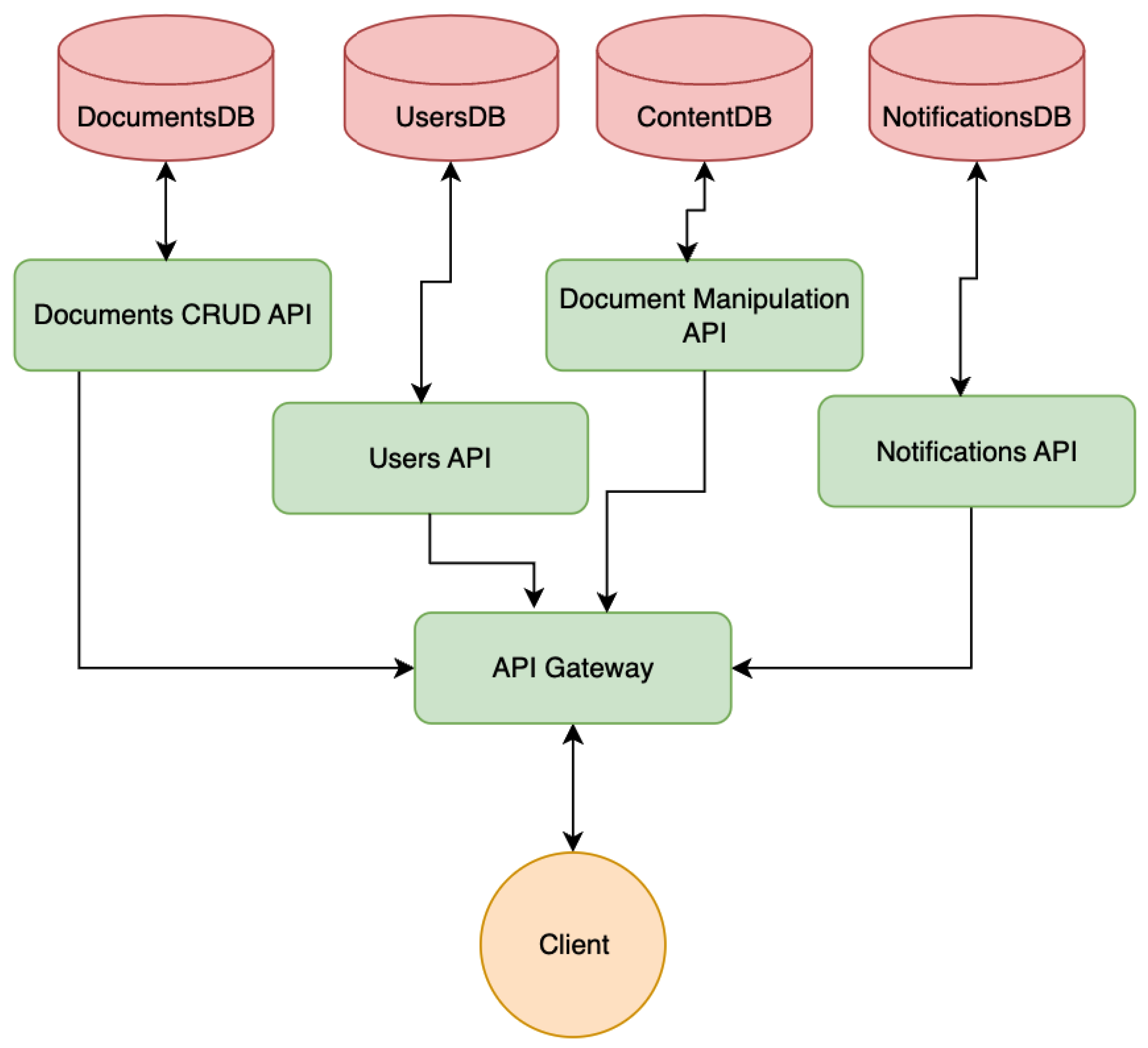
Figure 2.
Example of an Event-driven messaging system.
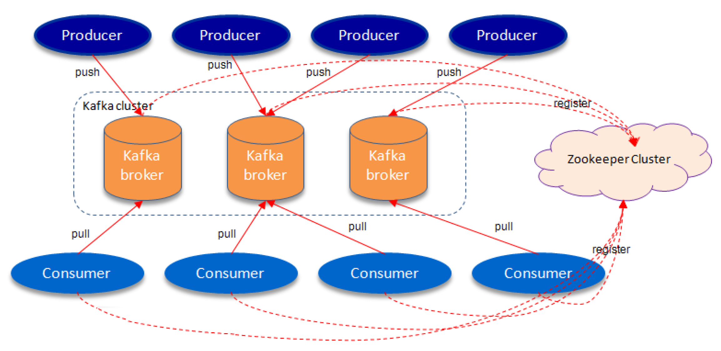
Figure 3.
SSE interaction between the client and server
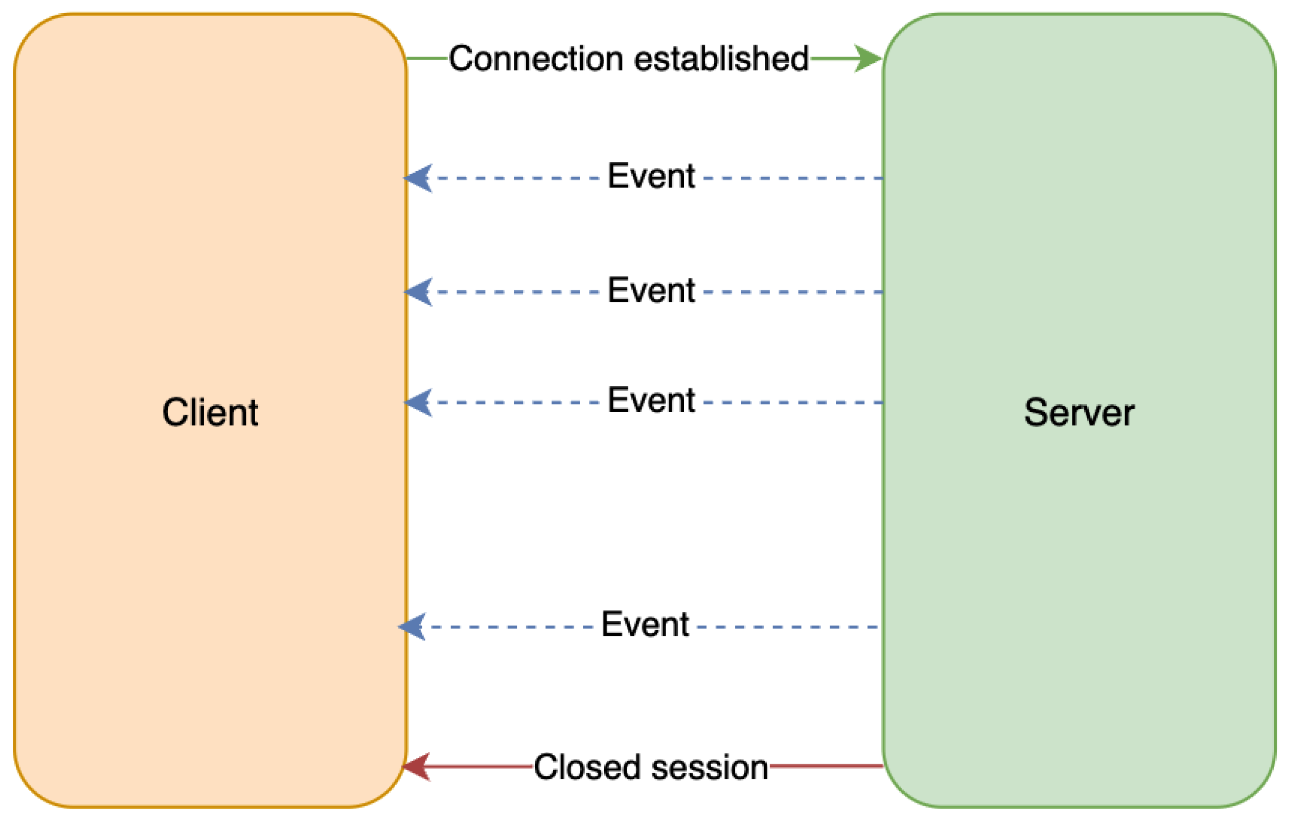
Figure 4.
Application diagram with a messaging layer.
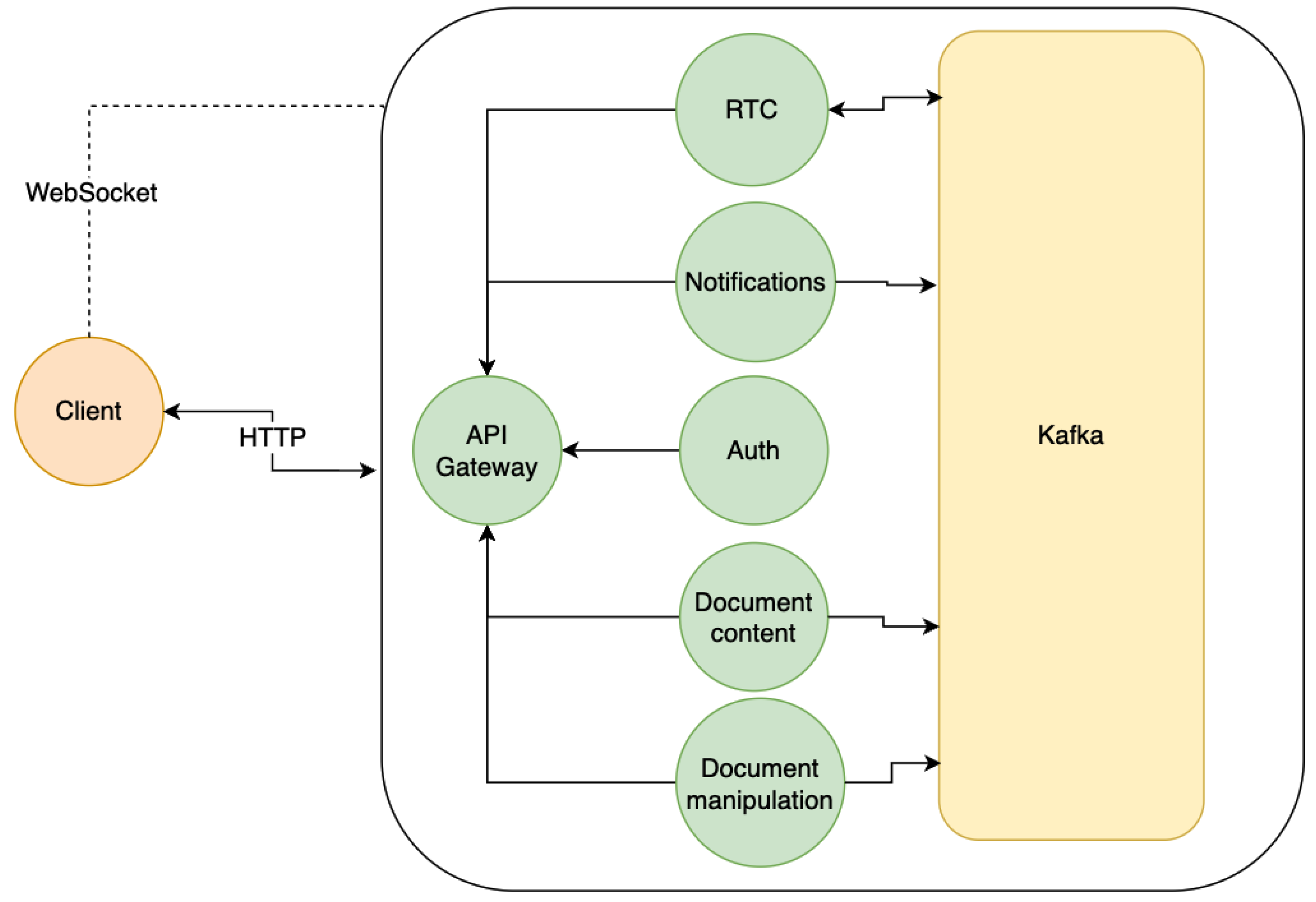
Figure 5.
Application diagram with storage layer.
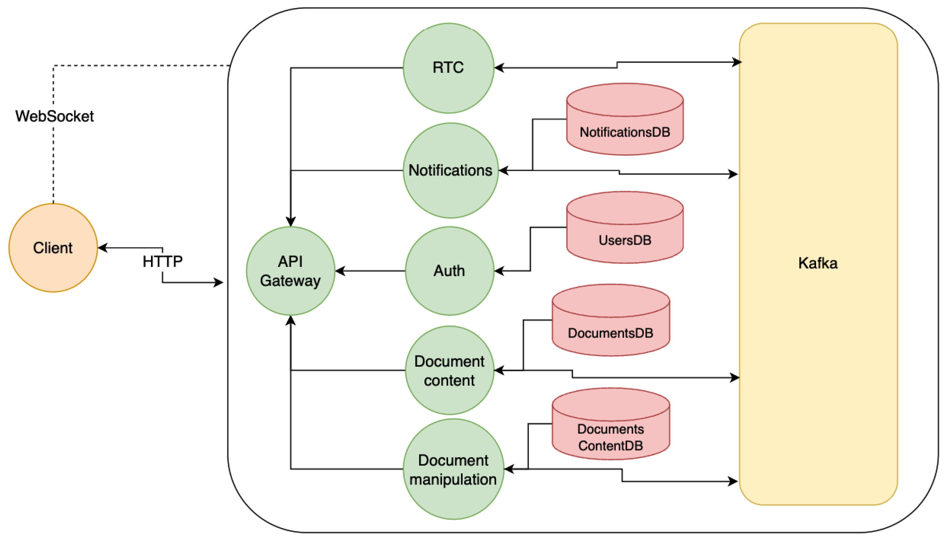
Figure 6.
Kubernetes cluster diagram
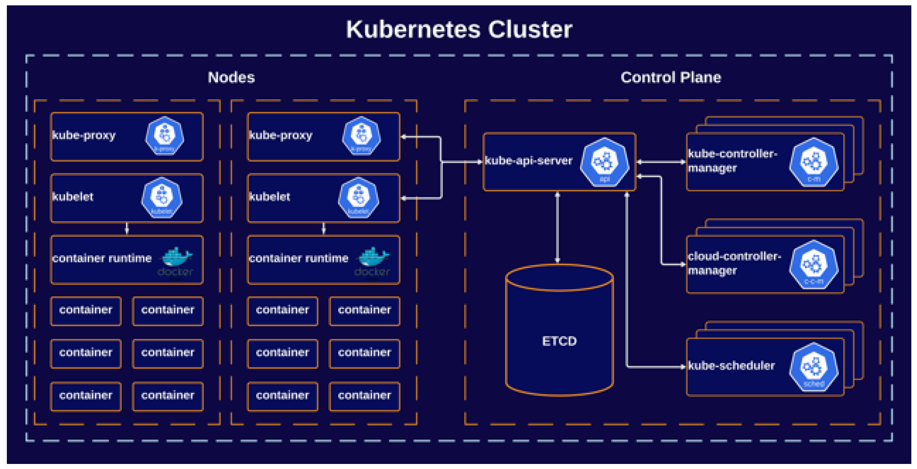
Figure 7.
Producer-consumer queue.
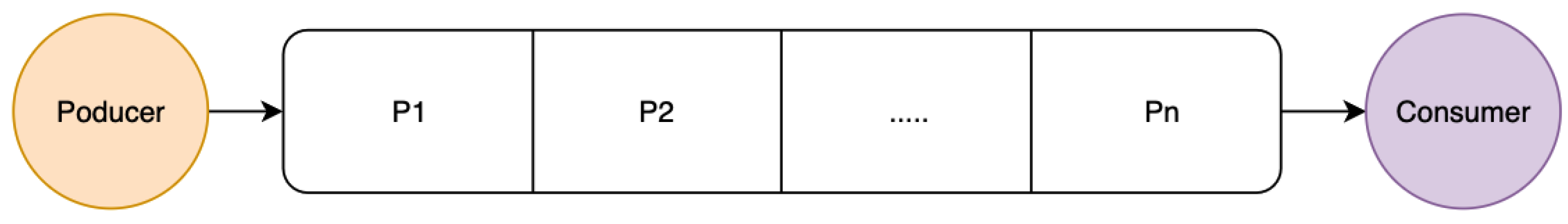
Figure 8.
Distributed queue system.
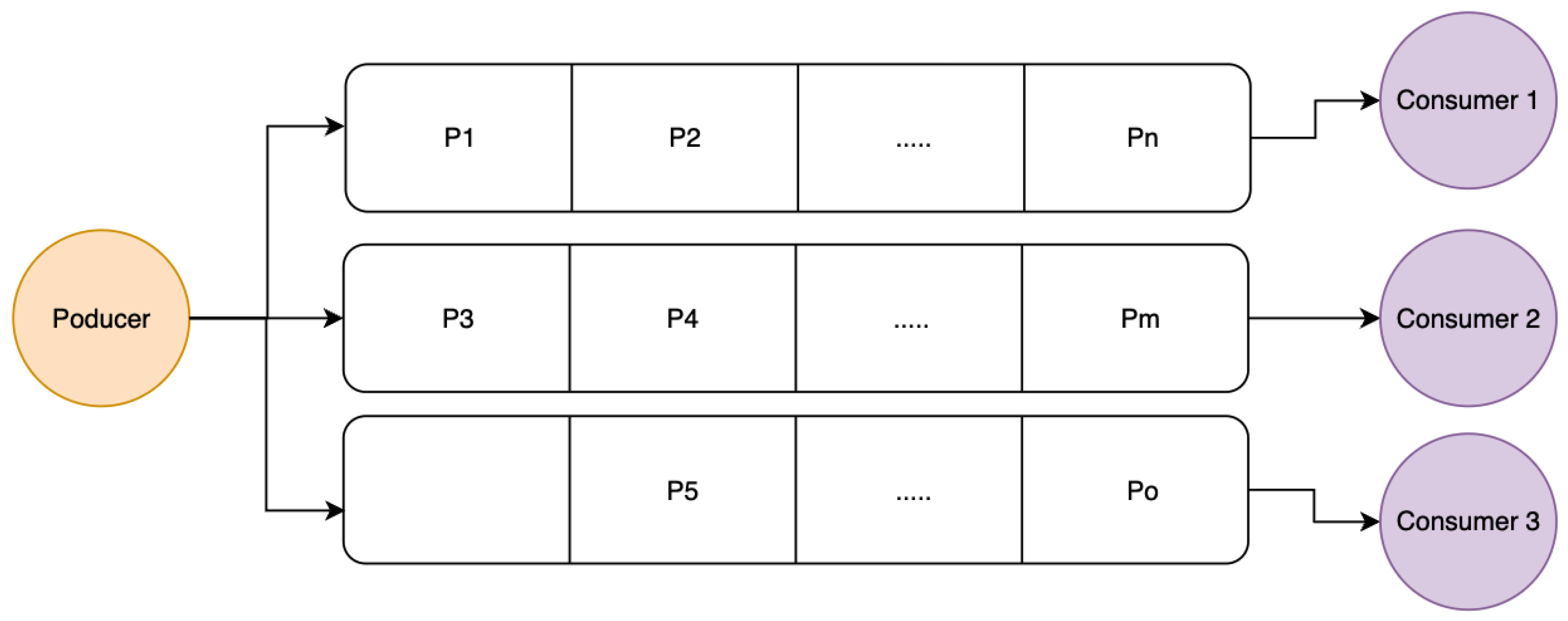
Figure 9.
Sample of Kafka topics for a collaborative system design
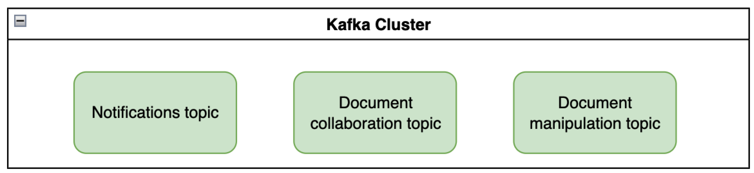
Figure 10.
Group consumer
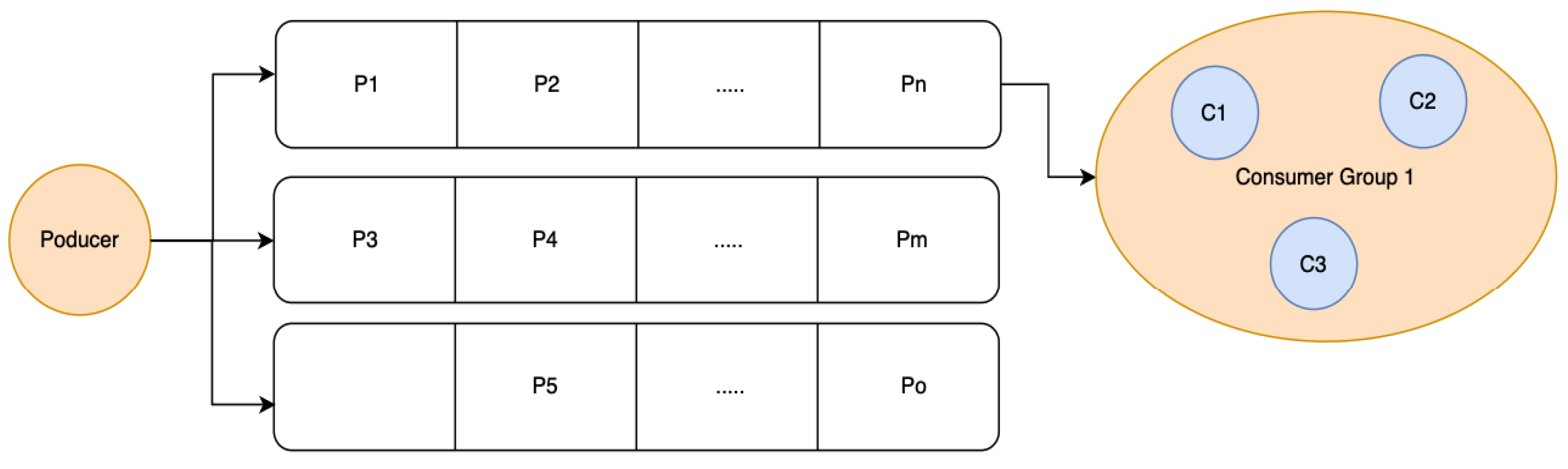
Figure 11.
Multiple group consumer
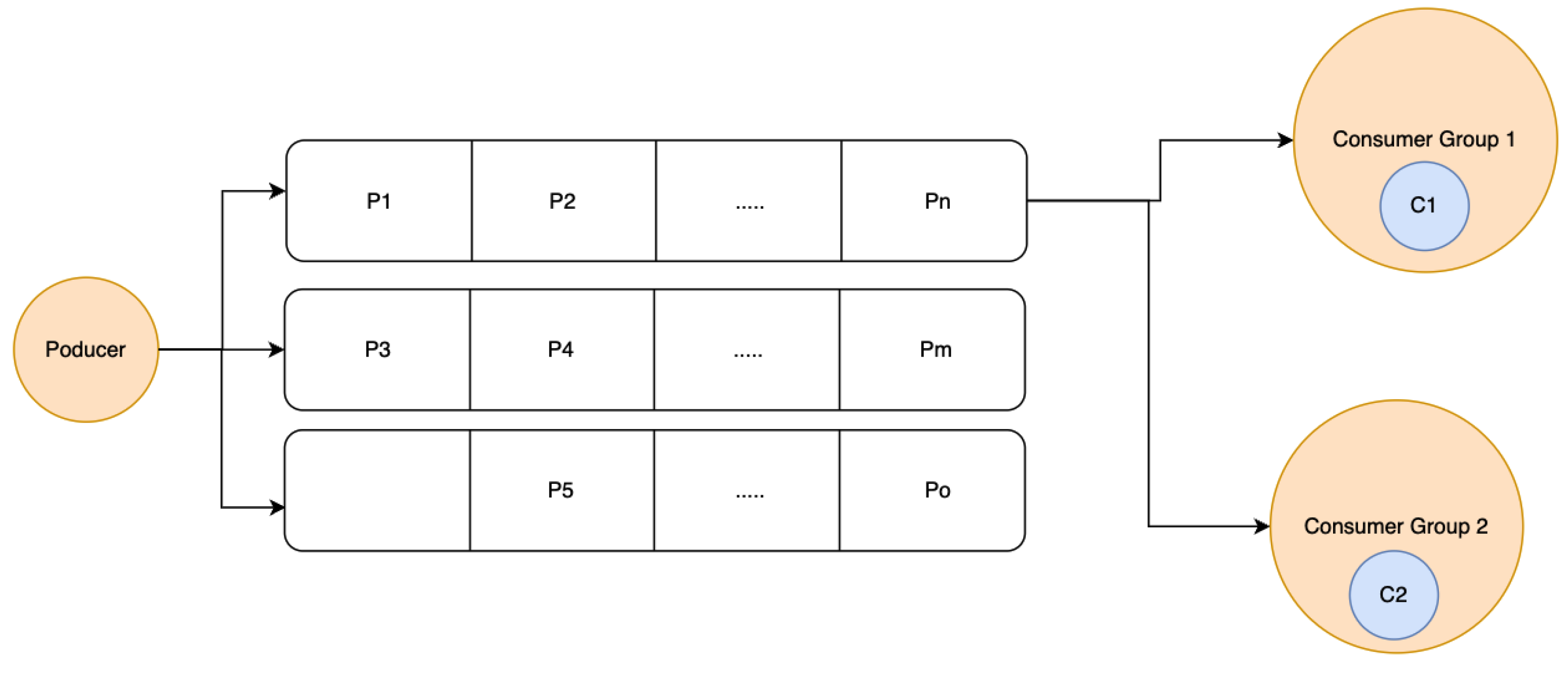
Figure 12.
The structure of a JWT token
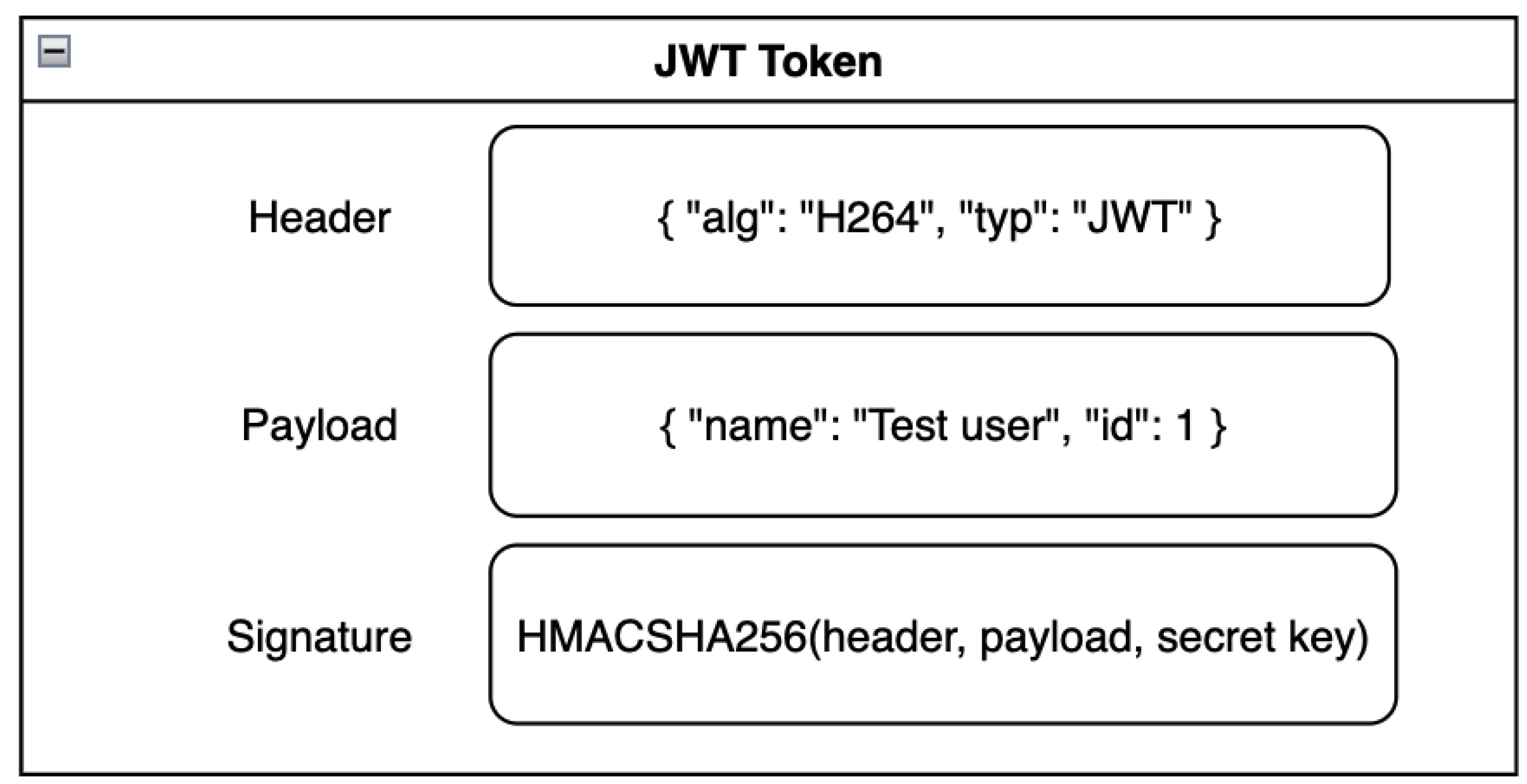
Figure 13.
Executing a transaction between clients
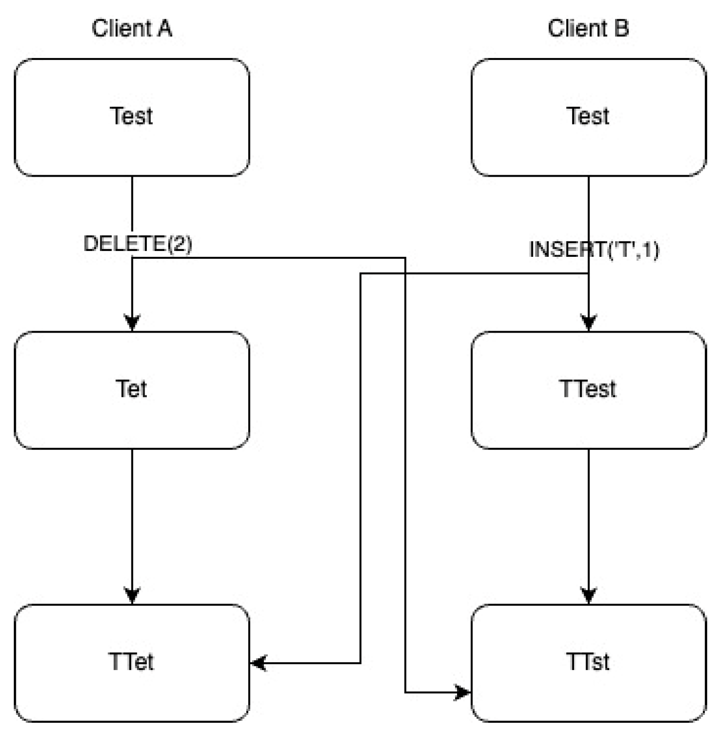
Figure 14.
Multi-client consumers on a single server.
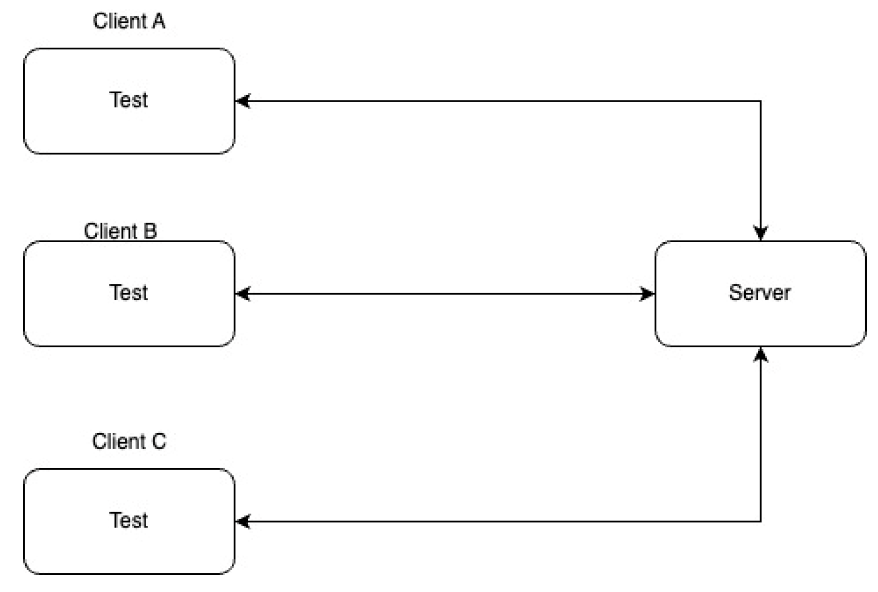
Figure 15.
Forwarding events between services.
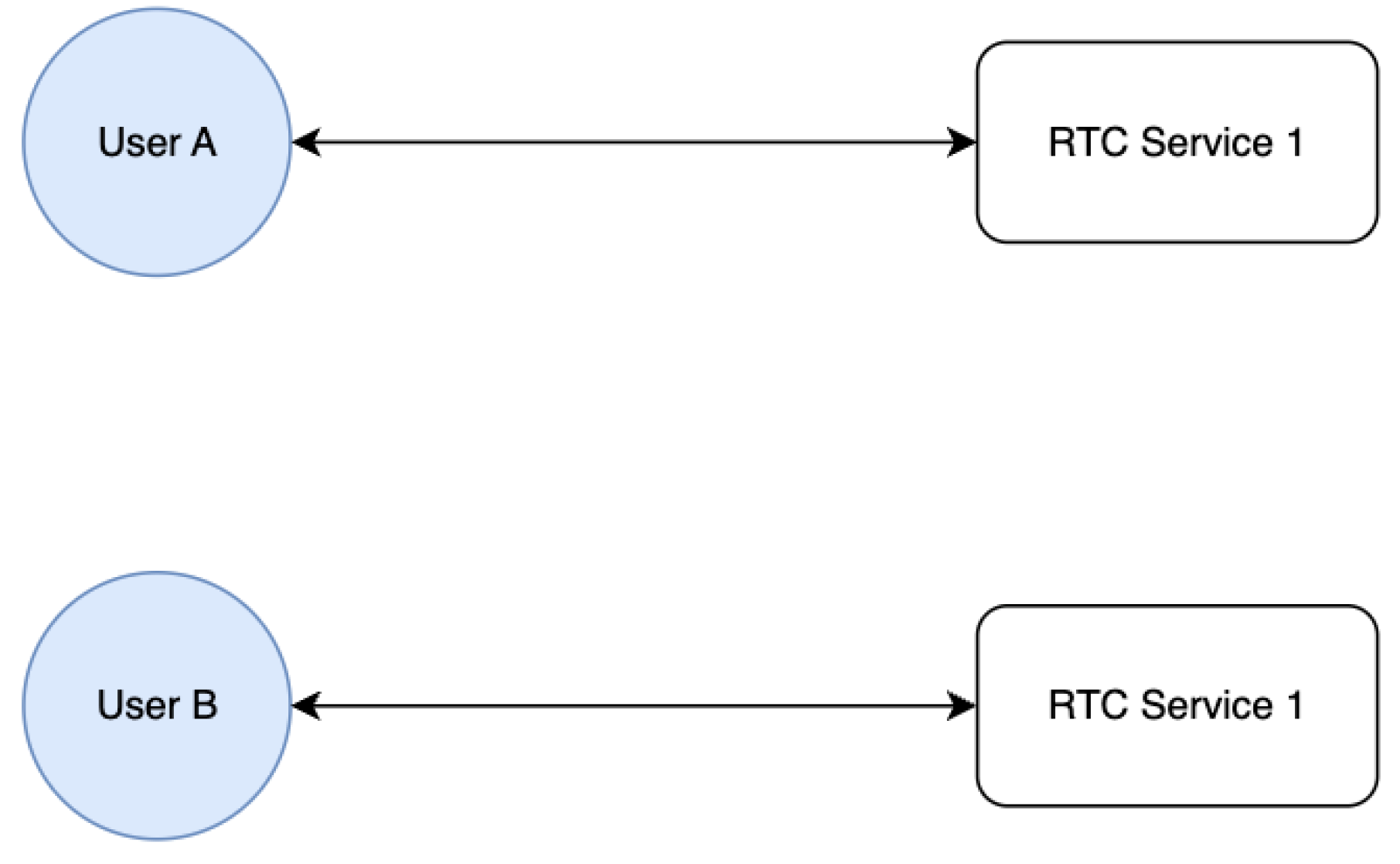
Figure 16.
Introducing a bridge for physically isolated services.
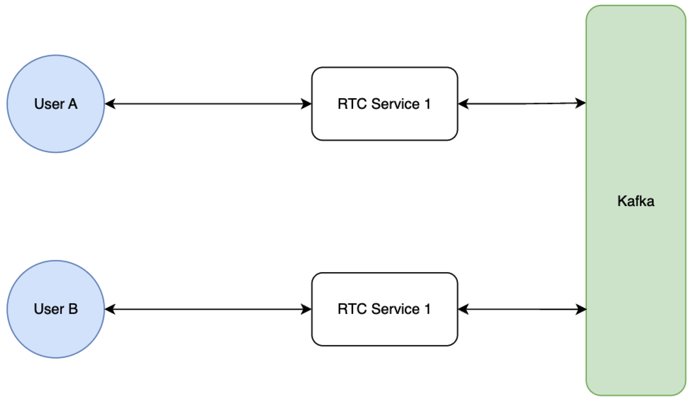
Figure 17.
JVM Test 1 - resource comparison.
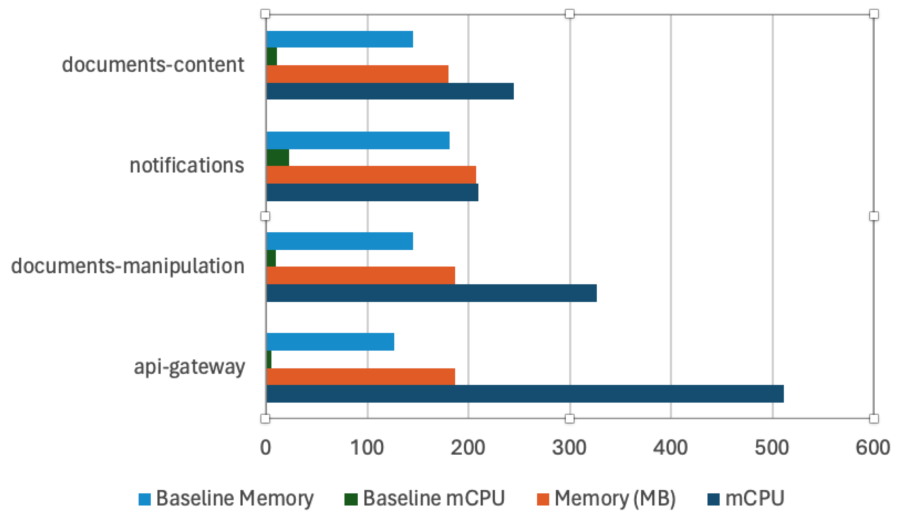
Figure 18.
JVM Test 1 - CPU consumption evolution.
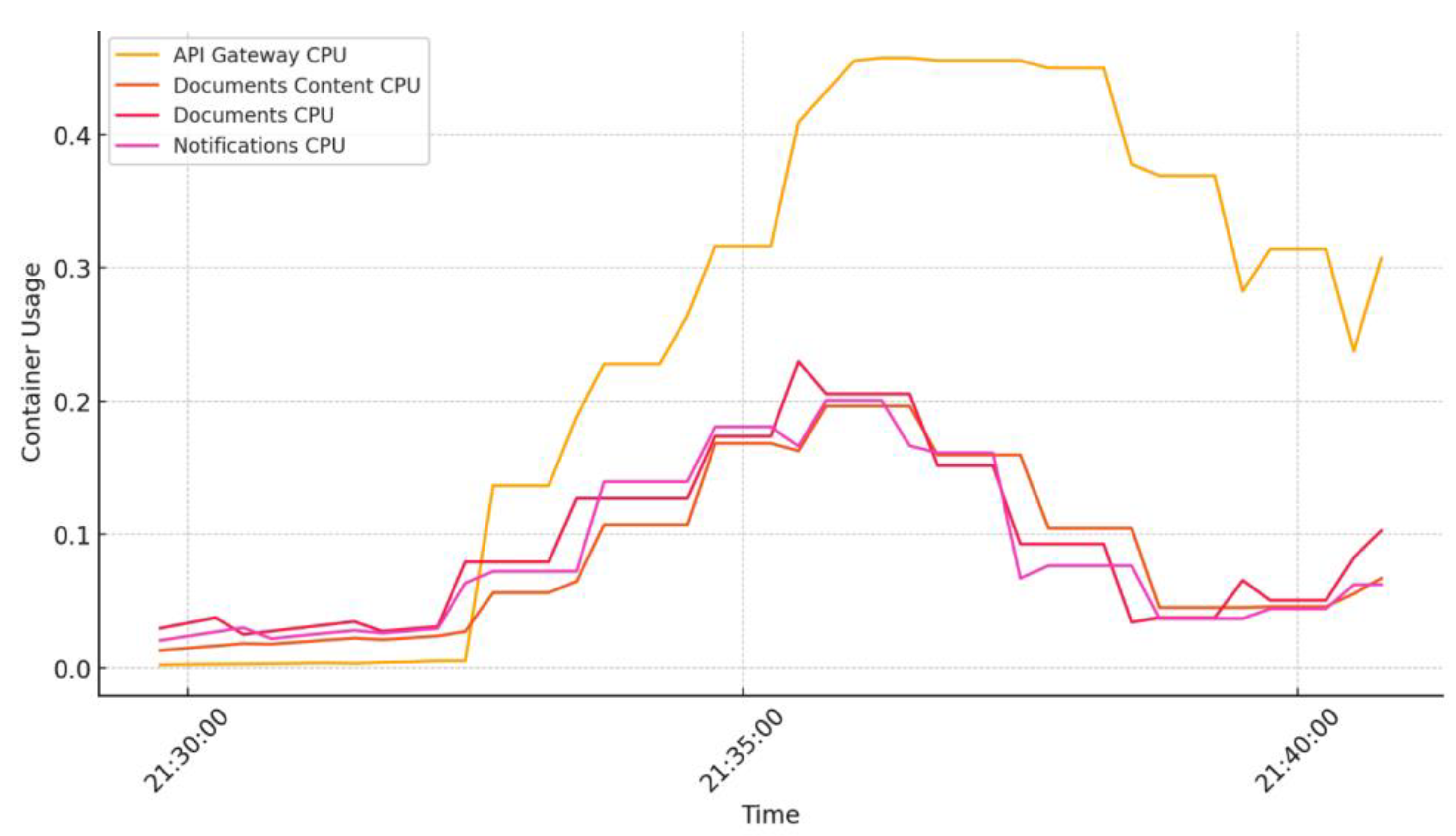
Figure 19.
JVM Test 1 - RAM consumption evolution.
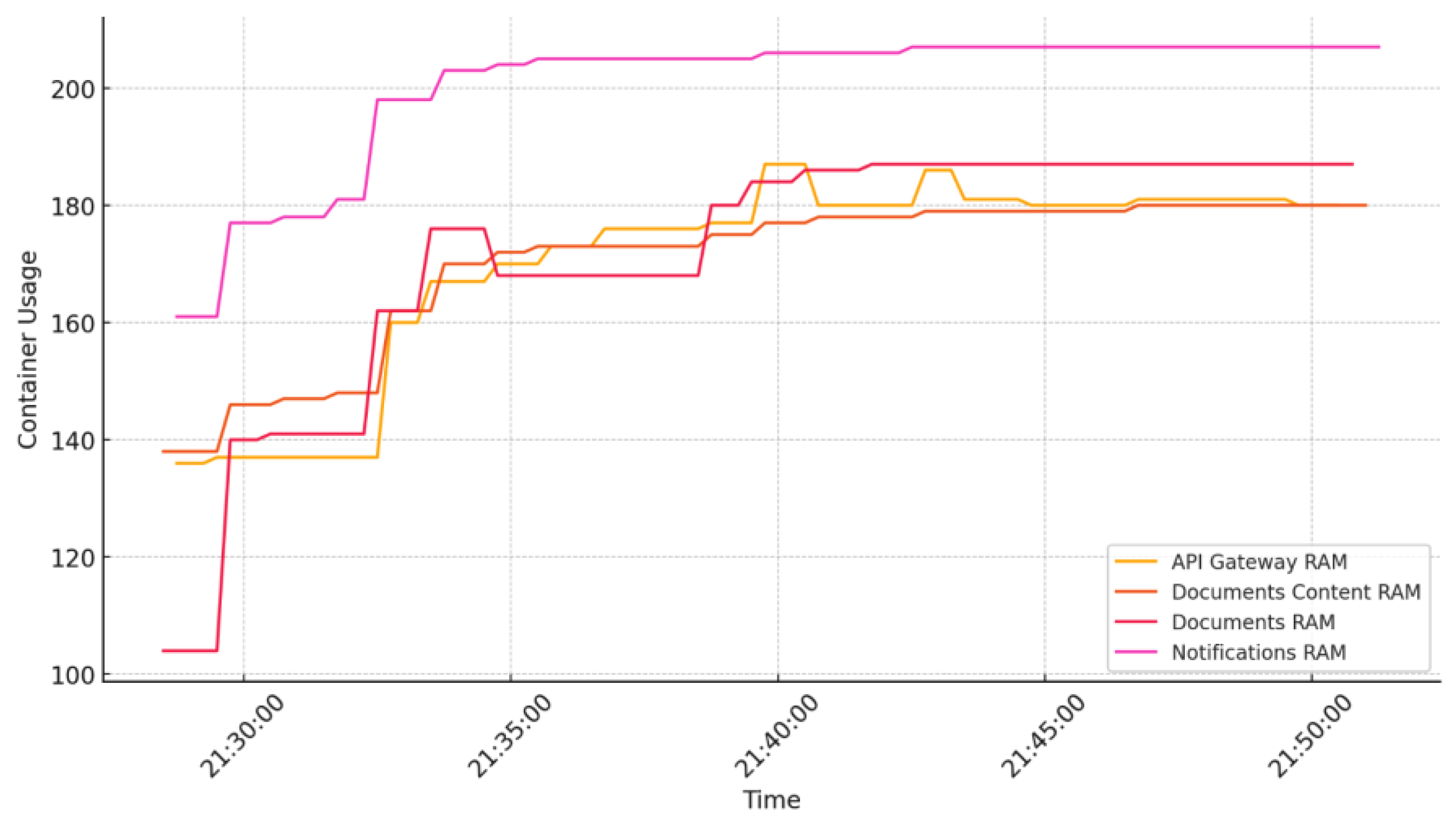
Figure 20.
JVM Test 2 - resource comparison.
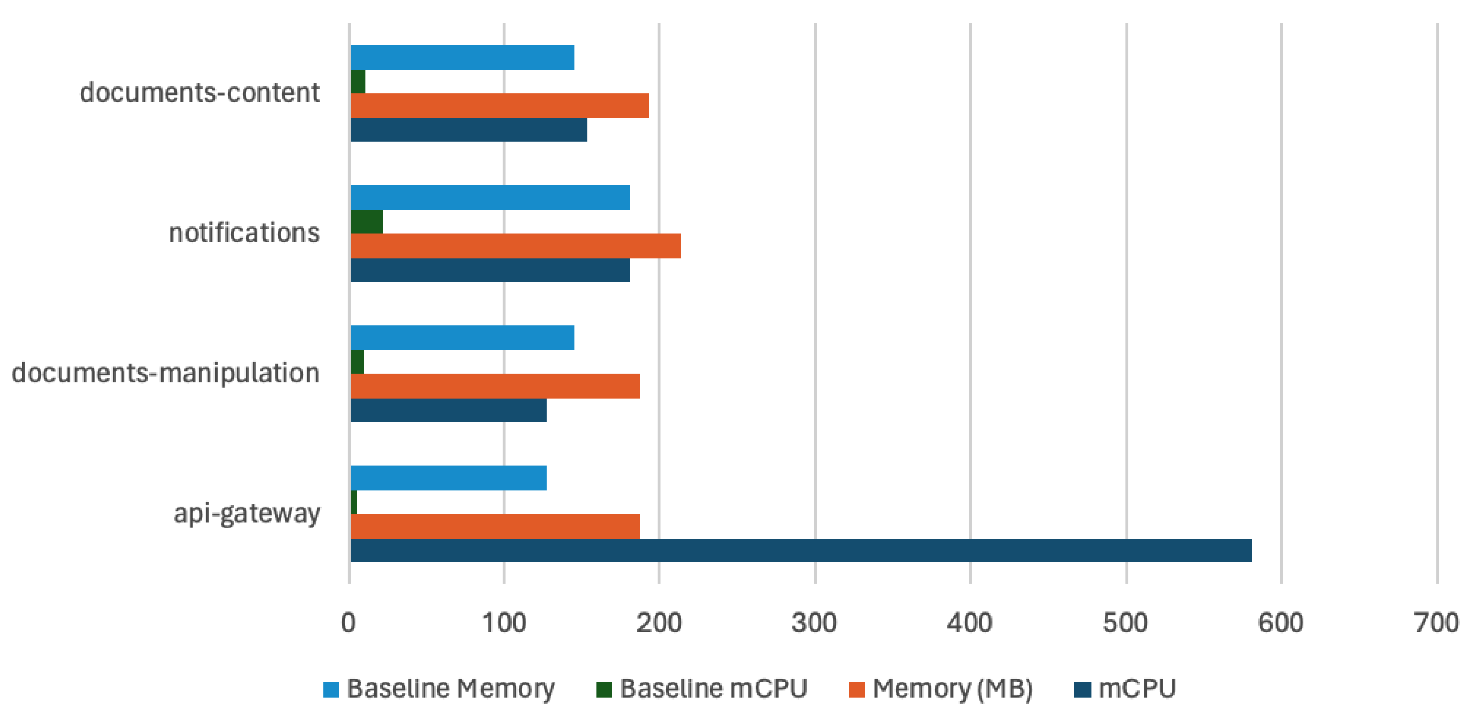
Figure 21.
JVM Test 2 - CPU consumption evolution.
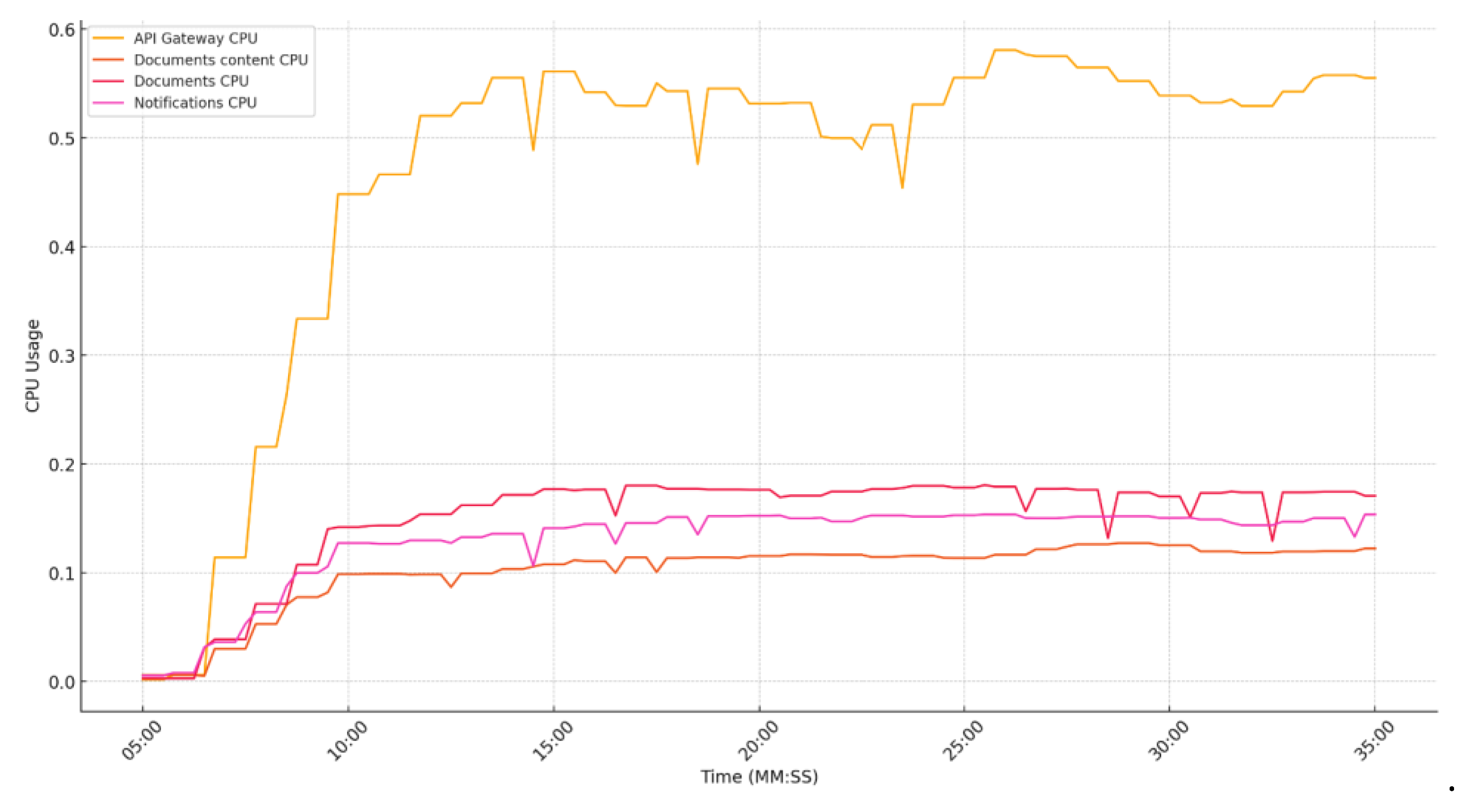
Figure 22.
JVM Test 2 - RAM consumption evolution.
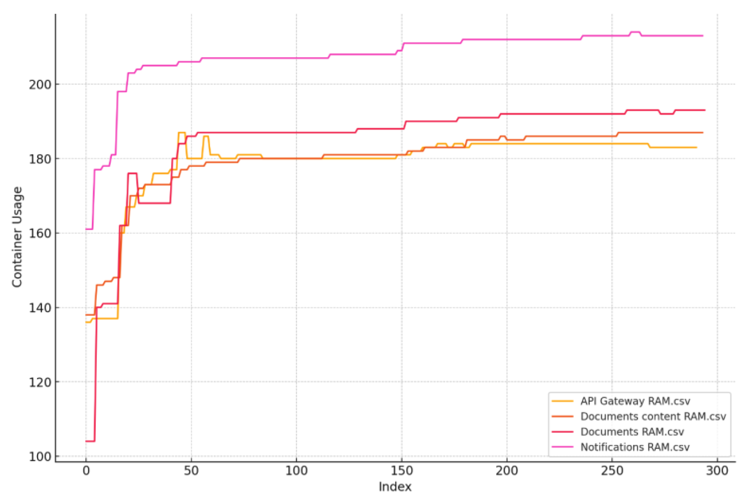
Figure 23.
JVM Test 3 - resource comparison.
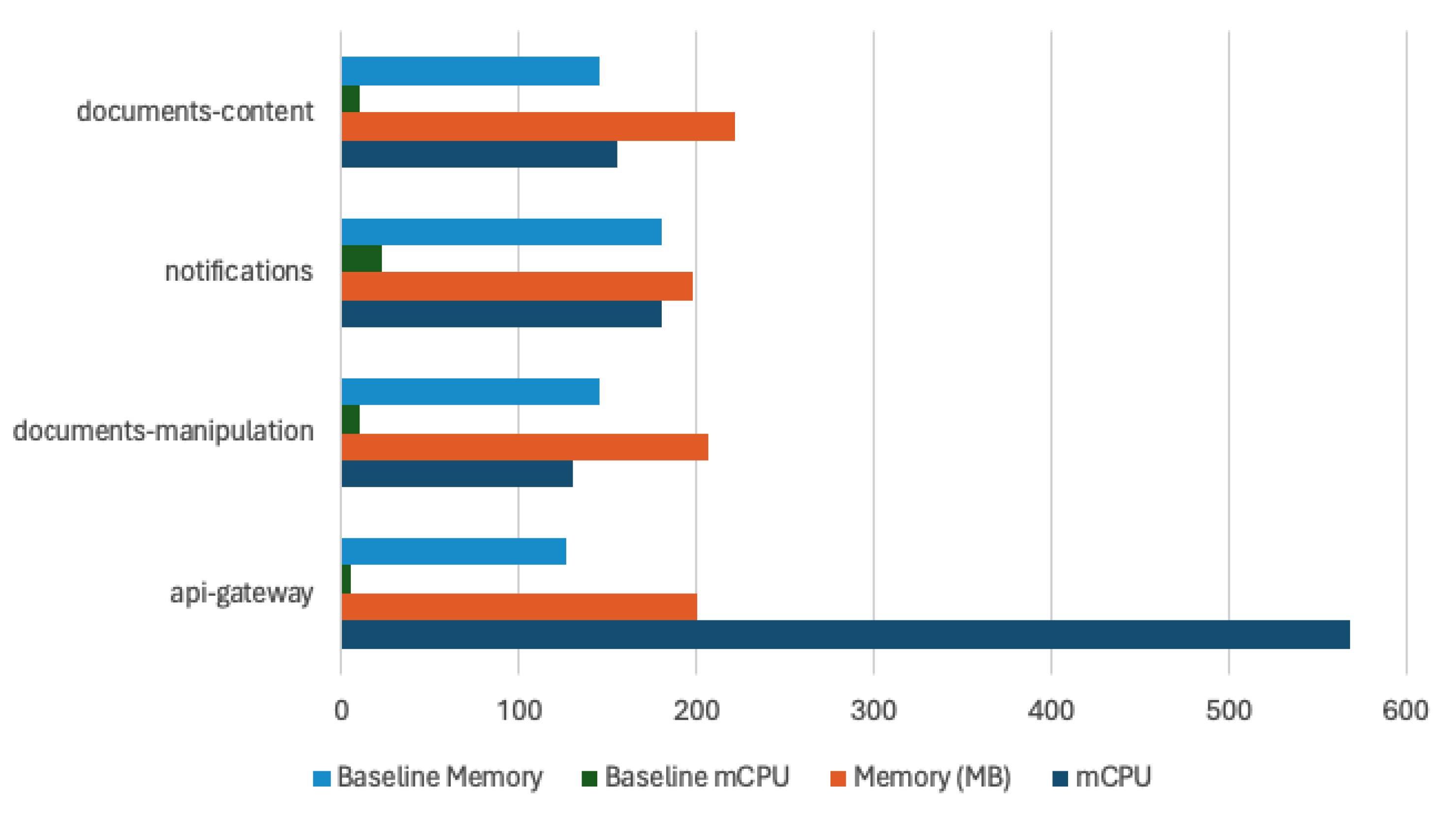
Figure 24.
JVM Test 3 - CPU consumption evolution.
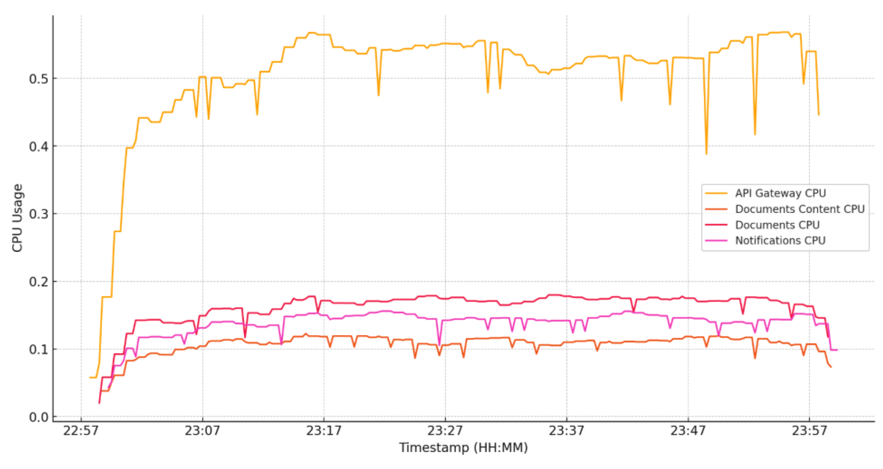
Figure 25.
JVM Test 3 - RAM consumption evolution.
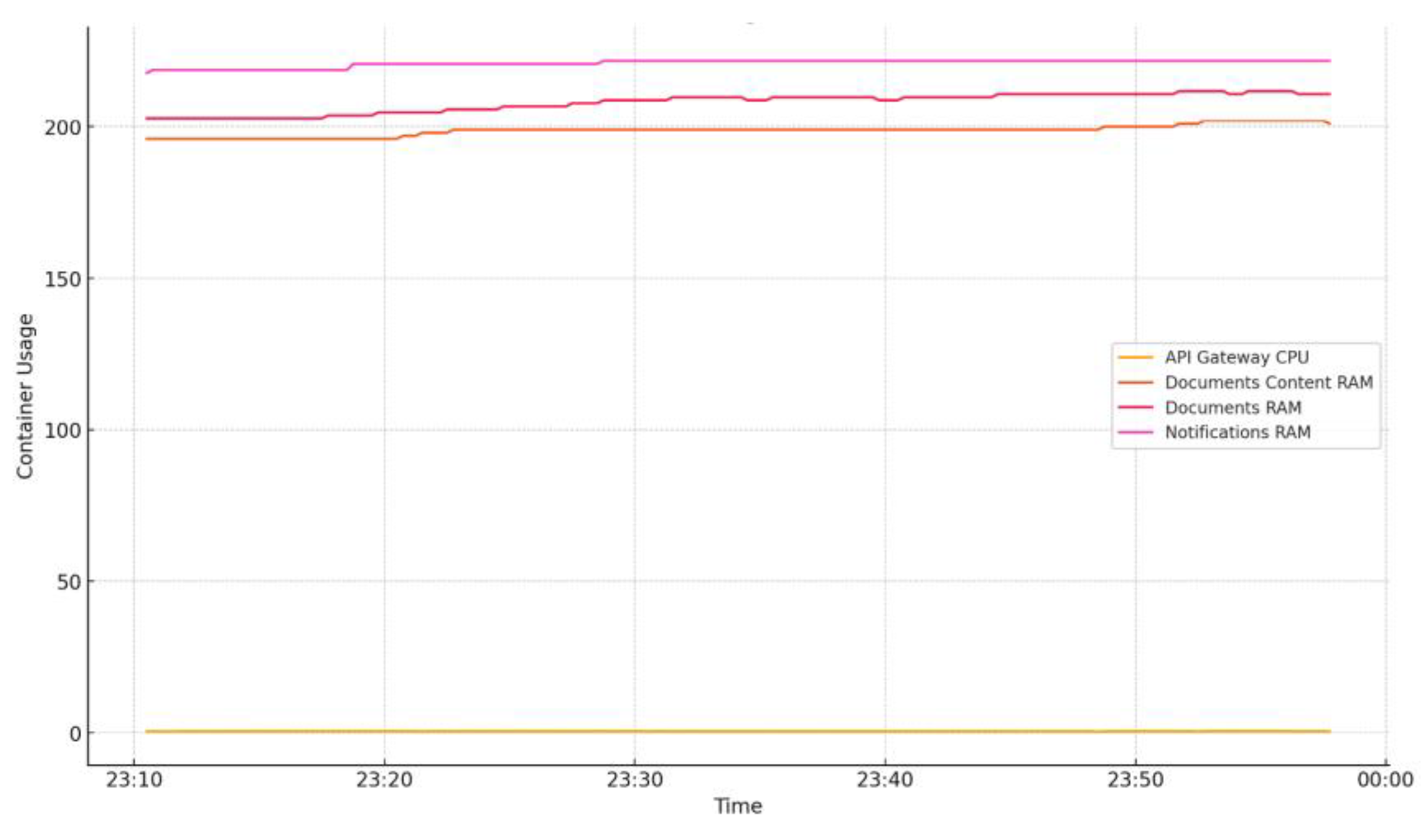
Figure 26.
GraalVM Test 1 - resource comparison.
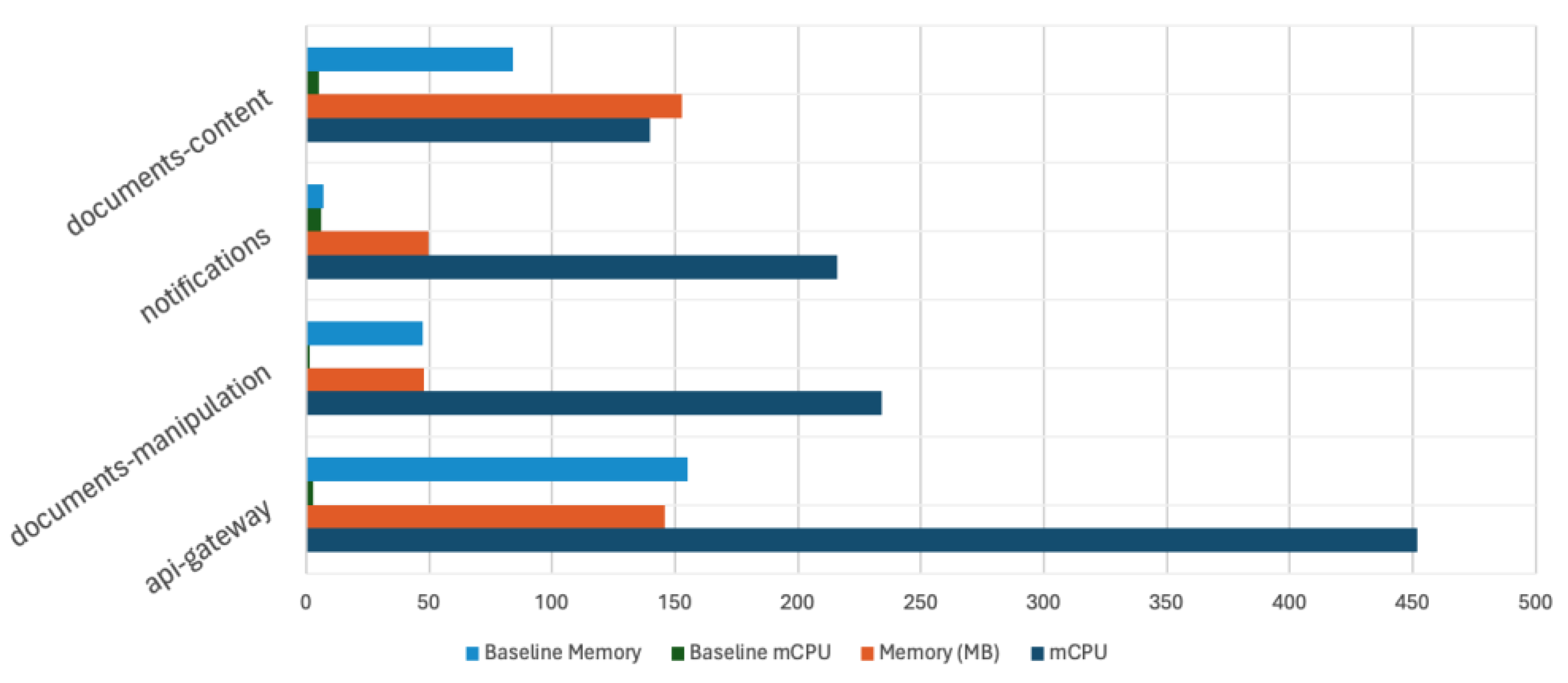
Figure 27.
GraalVM Test 1 - CPU consumption evolution.
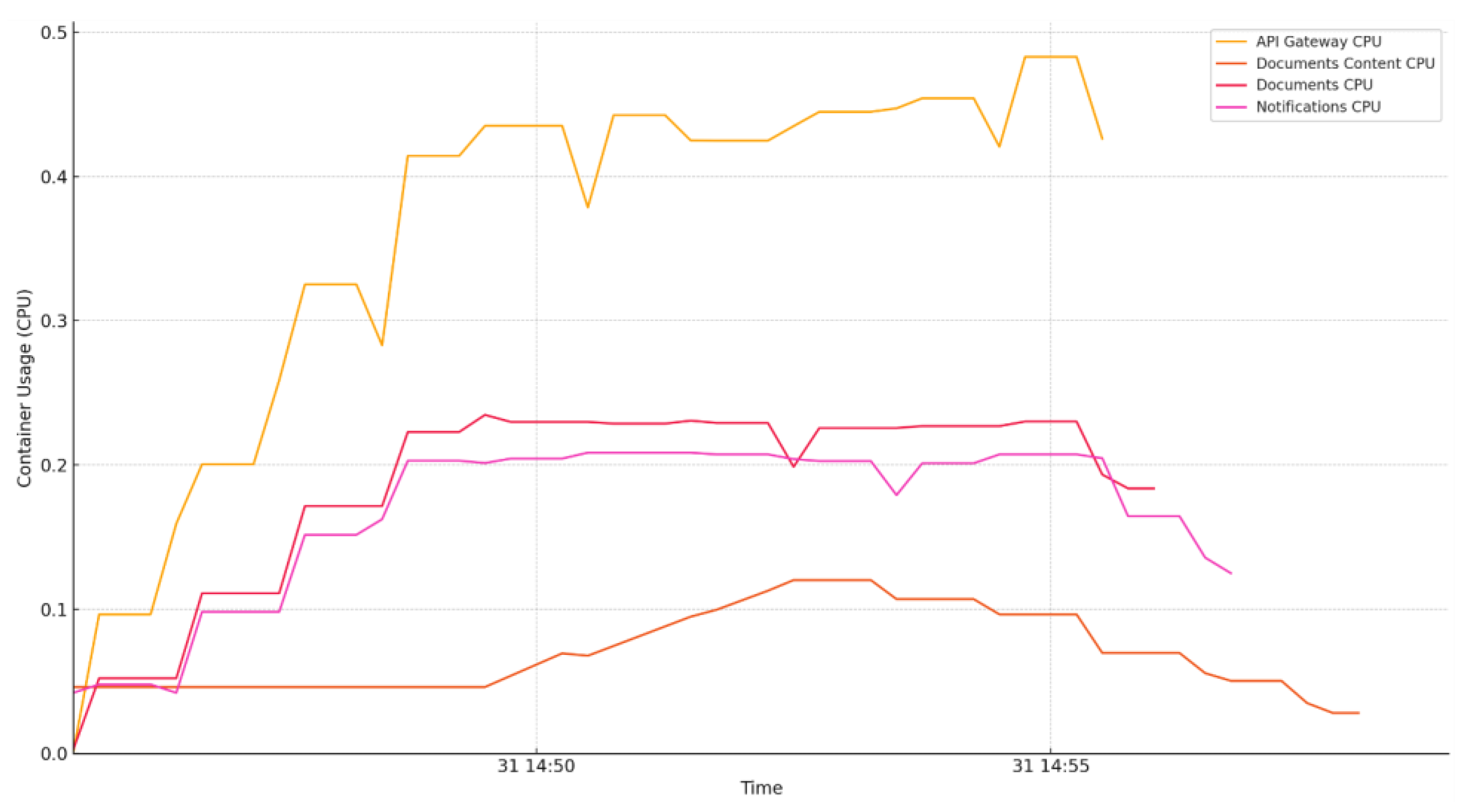
Figure 28.
GraalVM Test 1 - RAM consumption evolution.
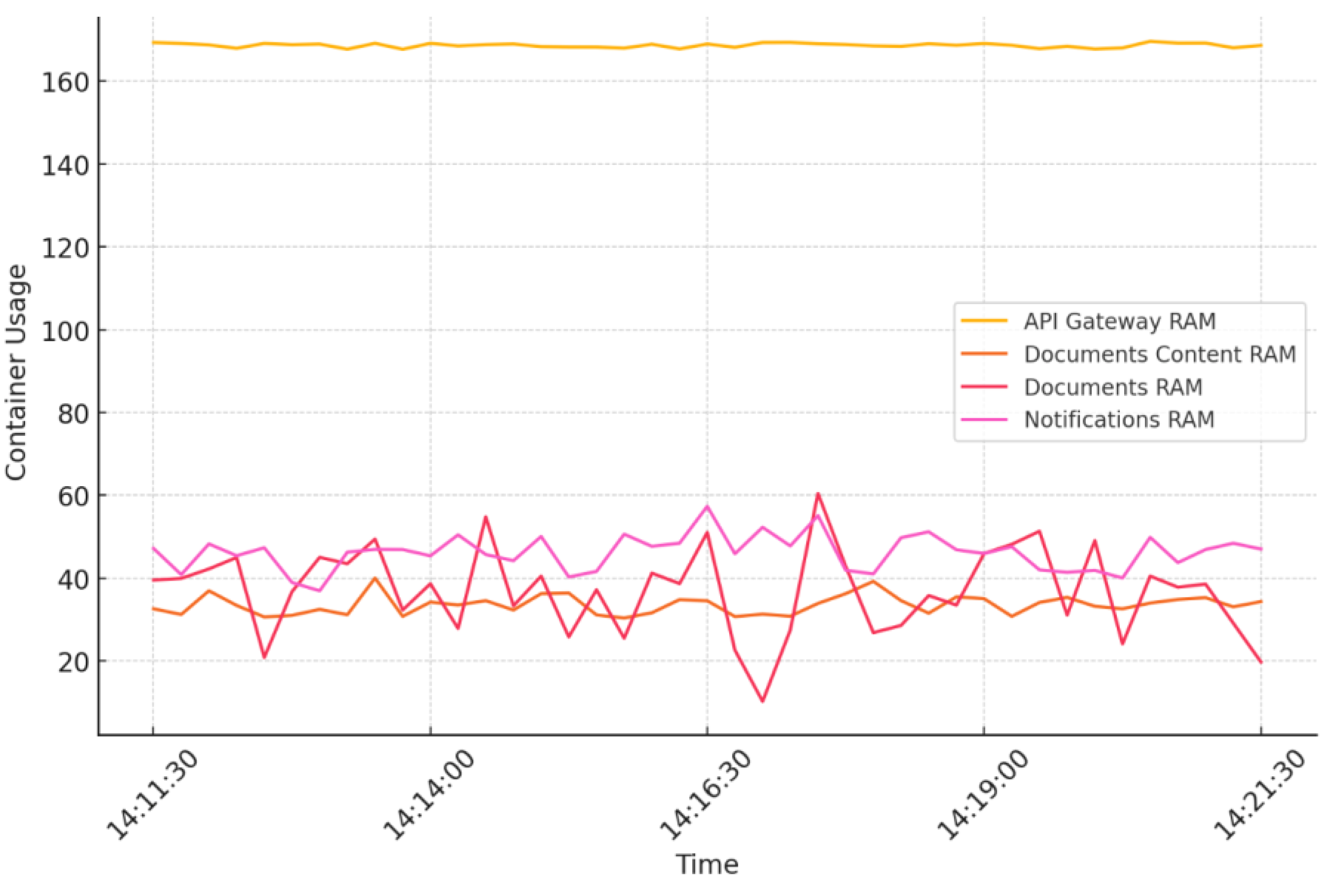
Figure 29.
GraalVM Test 2 - resource comparison.
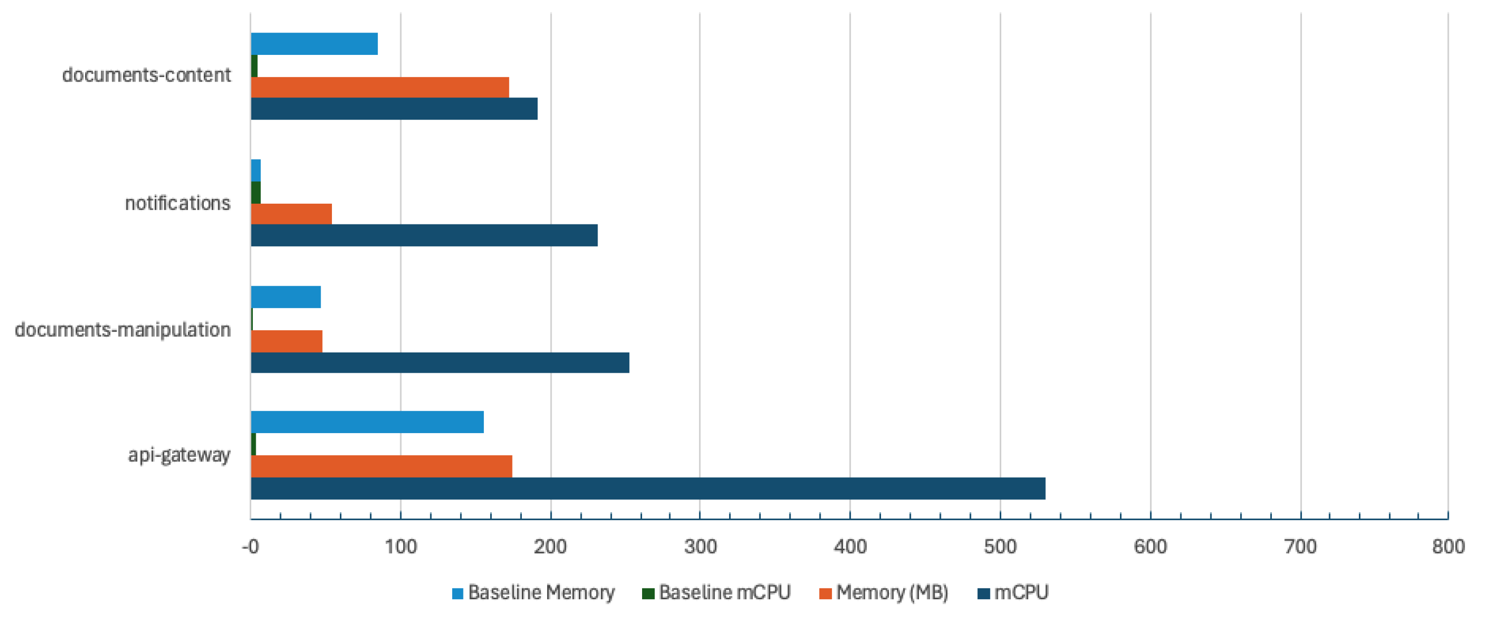
Figure 30.
GraalVM Test 2 - CPU consumption evolution.
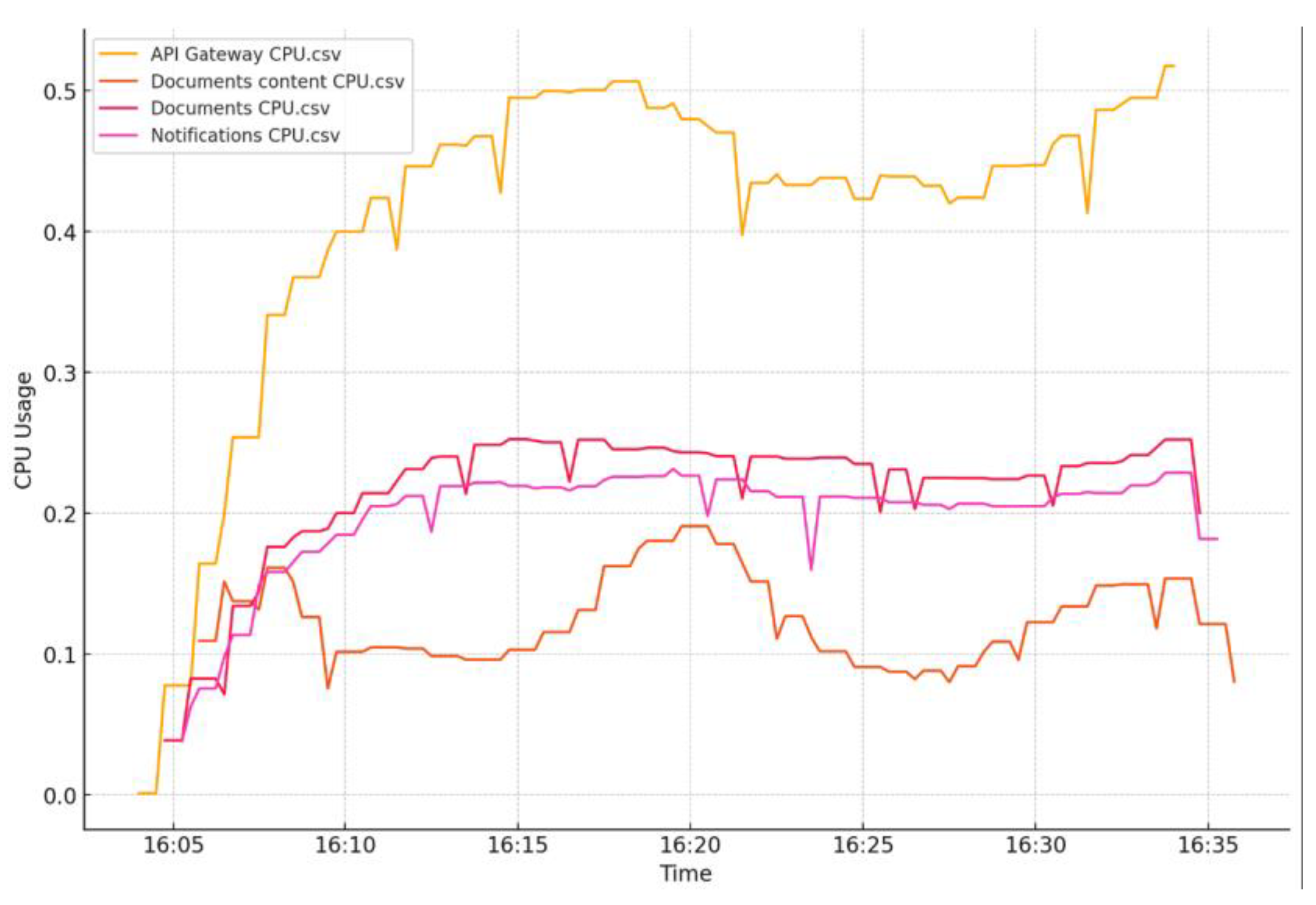
Figure 31.
GraalVM Test 2 - RAM consumption evolution.
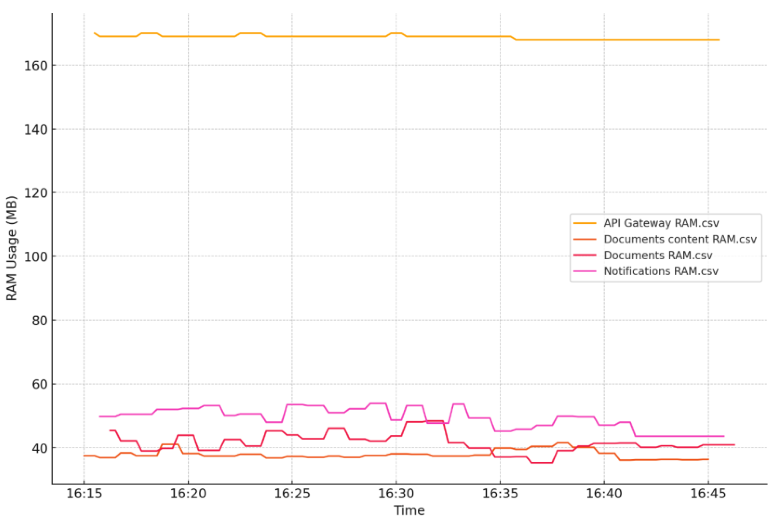
Figure 32.
GraalVM Test 3 - resource comparison.
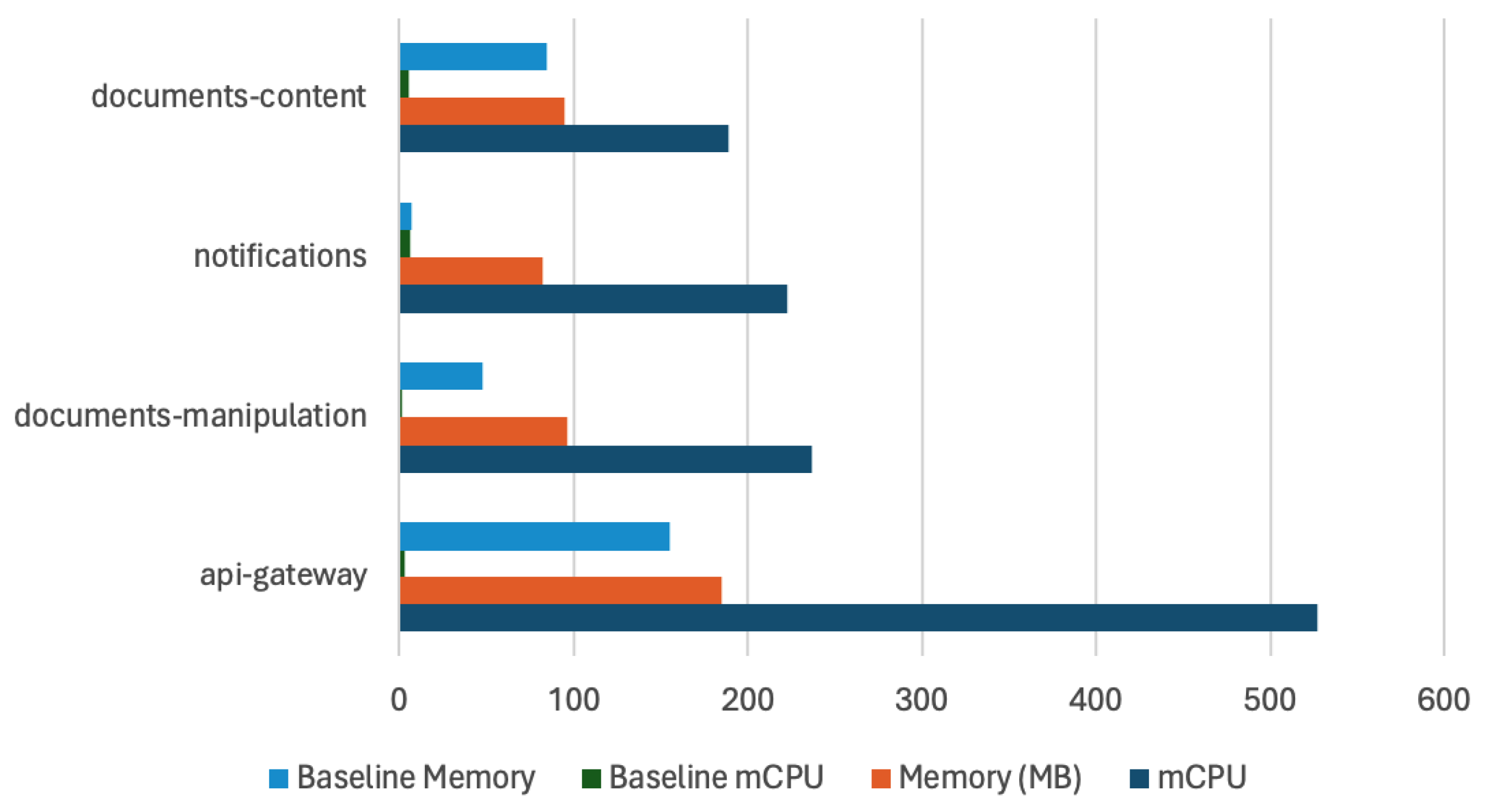
Figure 33.
GraalVM Test 3 - CPU consumption evolution.
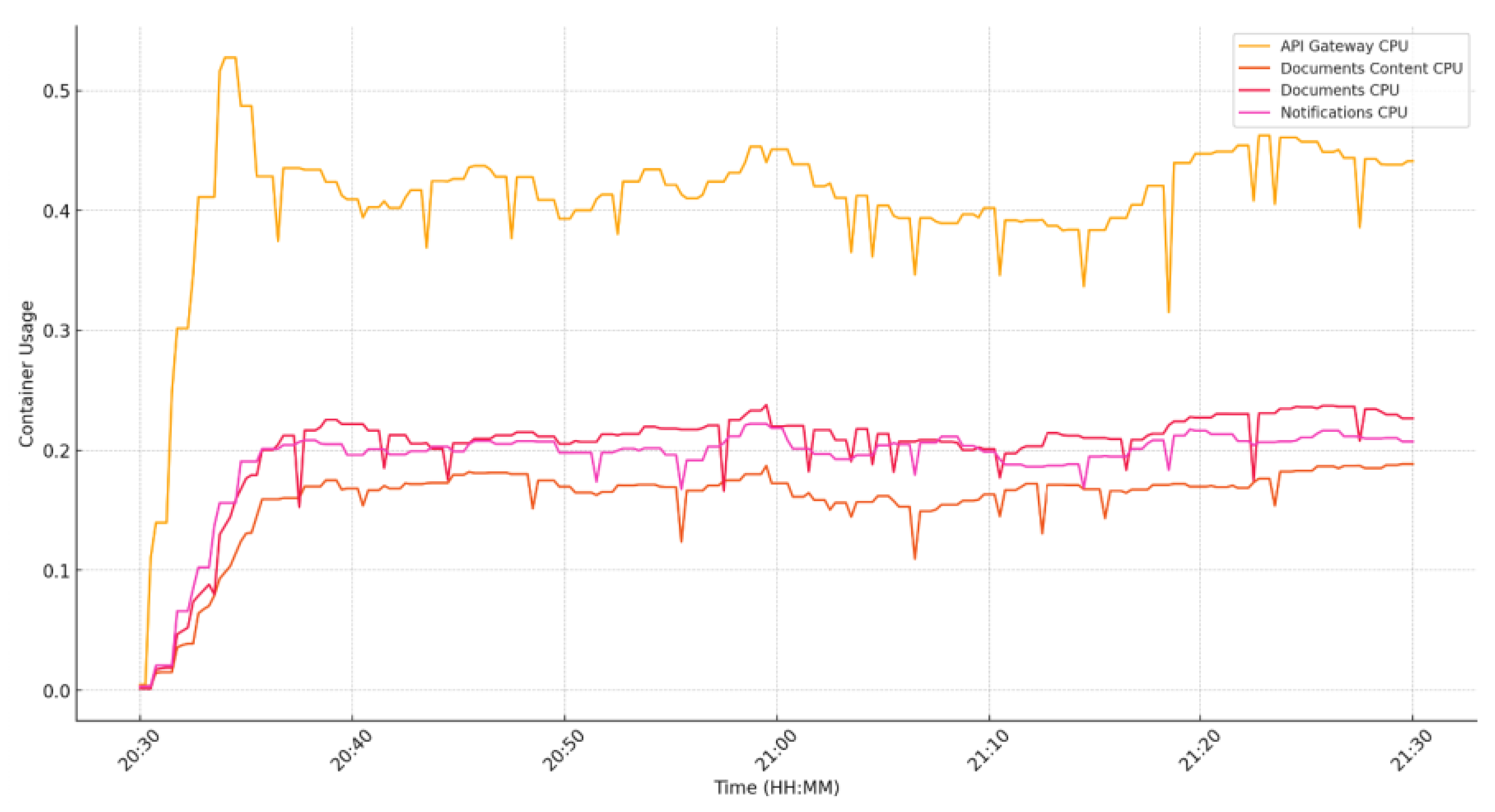
Figure 34.
GraalVM Test 3 - RAM consumption evolution.
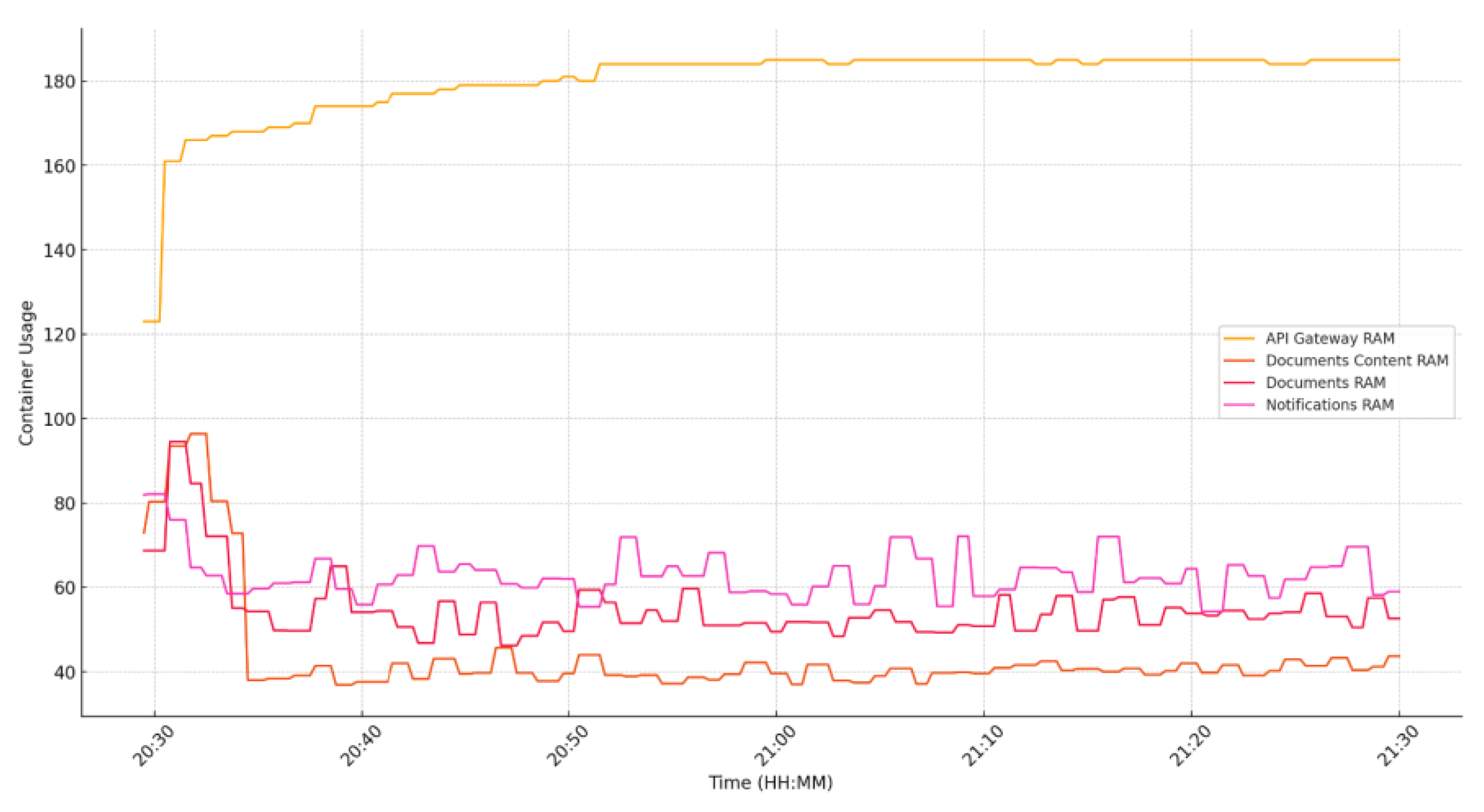
Figure 35.
Example of Percentile on response time histogram.
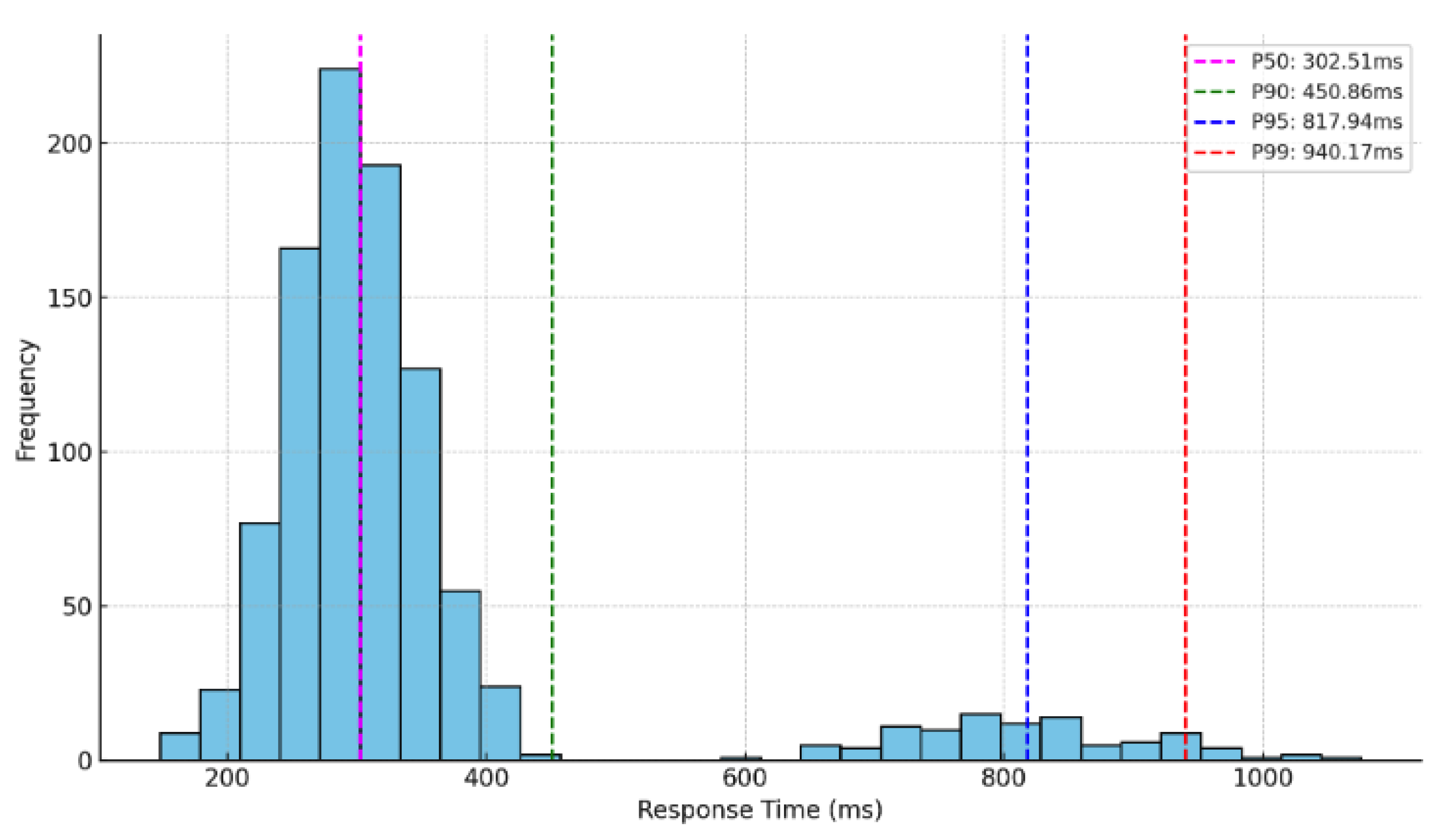
Figure 36.
JVM Response Time Histogram.
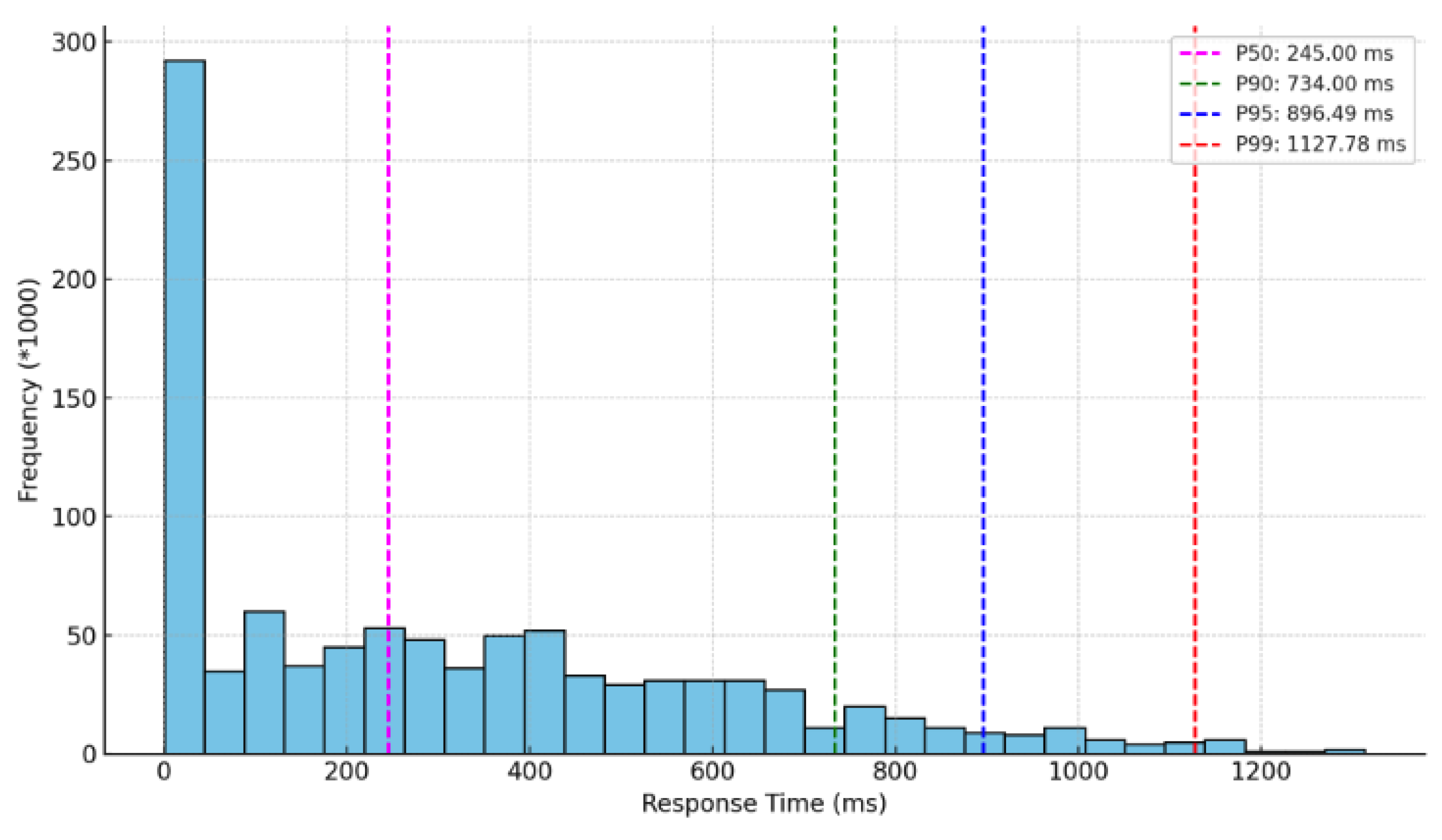
Figure 37.
GraalVM Response Time Histogram.


Table 1.
JVM idle CPU consumption
| Feature | mCPU |
| api-gateway | 5.1 |
| auth | 16.26 |
| document-manipulation | 10.13 |
| document-content-handler | 10.39 |
| RTC | 13.64 |
| notifications | 22.28 |
Table 2.
JVM RAM consumption
| Feature | RAM MB |
| api-gateway | 126.74 |
| auth | 162.84 |
| document-manipulation | 144.53 |
| document-content-handler | 145.5 |
| RTC | 152.48 |
| notifications | 180.2 |
Table 3.
GraalVM idle CPU consumption.
| Feature | mCPU |
| api-gateway | 3.08 |
| auth | 10.14 |
| document-manipulation | 1.62 |
| document-content-handler | 5.05 |
| RTC | 6.83 |
| notifications | 6.23 |
Table 4.
GraalVM RAM consumption.
| Feature | RAM MB |
|---|---|
| api-gateway | 155.02 |
| auth | 77.61 |
| document-manipulation | 47.30 |
| document-content-handler | 84.31 |
| RTC | 29.56 |
| notifications | 49.31 |
Table 5.
Opening connections stress-test JVM vs GraalVM
| System type | Opened connections |
|---|---|
| JVM | 9540 |
| GraalVM | 13648 |
Disclaimer/Publisher’s Note: The statements, opinions and data contained in all publications are solely those of the individual author(s) and contributor(s) and not of MDPI and/or the editor(s). MDPI and/or the editor(s) disclaim responsibility for any injury to people or property resulting from any ideas, methods, instructions or products referred to in the content. |
© 2024 by the authors. Licensee MDPI, Basel, Switzerland. This article is an open access article distributed under the terms and conditions of the Creative Commons Attribution (CC BY) license (http://creativecommons.org/licenses/by/4.0/).
Copyright: This open access article is published under a Creative Commons CC BY 4.0 license, which permit the free download, distribution, and reuse, provided that the author and preprint are cited in any reuse.


