
Submitted:
09 August 2024
Posted:
09 August 2024
You are already at the latest version
Abstract
The existing PDC(Polycrystalline Diamond Compacts) -cone hybrid bit bearing adopts a unilateral support structure, which is prone to stress concentration in the journal area, resulting in fracture and wear failure of the bearing, thus reducing the service life of the hybrid bit. In this paper, a new type of double supported bearing hybrid bit is proposed. The static strength analysis of unilateral and bilateral support bearing structures is carried out by finite element simulation, and the stress and strain distribution of the two structures under the load of 20KN-100KN is obtained. Experimental devices for unilateral and bilateral support bearing structures are designed and manufactured to complete 50KN-100KN static pressure loading experiments. The results showed that the stress and strain of unilateral and bilateral support bearing increased linearly with the increase of load. Compared with unilateral bearing, when the load was 100KN, the maximum Mises stress of bilateral bearing decreased from 358.80MPa to 211.10MPa, with a decrease of 41.16%. The maximum contact stress decreased from 415.20MPa to 378.10MPa, decreased by 8.94%, and the maximum principal strain decreased from 11.01e-4 to 9.71e-4, decreased by 11.81%. The axial strain in the danger zone was reduced by 14.68% and 17.35%, respectively. It is found that the contact stress of the simulation data is highly correlated with the bearing life, and the service life of the bilateral bearing bit is increased by 8.94%. The simulation data and experimental results provide data support for the production of hybrid bits with bilateral bearing support.
Keywords:
hybrid bit
; bearing
; strength analysis
; bilateral support
; stress and strain
1. Introduction
The cutting structure of the PDC- cone hybrid bit is composed of a fixed PDC cutting structure and a cone cutting structure (Figure 1). PDC- cone hybrid bit is mainly used in the following special situations: (1) Deep wells and ultra-deep wells. The largest well depth in Xinjiang and Sichuan region of China has exceeded 10,000 meters. Due to the difficulty of deep formation drilling, a single PDC bit can not effectively break rocks. (2) Directional wells and horizontal wells. The tool face of PDC bit is unstable, and the torque fluctuates greatly, resulting in poor control of the well trajectory. (3) Heterogeneous formation containing gravels etc. PDC bit is easy to break teeth, resulting in bit failure. (4) Hard formation, PDC bit teeth wear faster, and the mechanical penetration rate of cone bit is too low [1,2,3,4,5,6,7].
At present, the PDC- cone hybrid bit bearing still adopts the existing cone bit bearing technology, and the bearing life largely determines the life of the whole bit. In order to further improve the strength of bearings and reduce the fracture failure caused by stress concentration, Ye Zhonglang and his team proposed a kind of cemented carbide bearing insert, which increased the bearing's impact resistance by plating silver on its body and inner wall, and improved the bit’s life under impact load environment [8].
Huang Zhiqiang et al. conducted mechanical and microstructure analysis on the failed roller cone bit bearings and found that stress concentration、impact and vibration caused by uneven fit clearance were a major cause of bearing fracture [9].
Wu Zebing et al. studied roller bearing with cone bit by combining the response surface method with the finite element method, and established the response surface optimization model by studying the relationship between stress distribution on the contact line and bearing modification parameters to obtain the optimal bearing design parameters [10,11].
Ye Zhonglang proposed that the method of increasing the insert can increase the strength of the stress concentration site; however, the sealing requirements are increased at the same time as the process is increased. Huang Zhiqiang found that a major cause of bearing breakage is due to stress concentration, shock and vibration, but did not give more details on how to reduce bearing breakage. Wu Zebing obtained the optimal design parameters of bearings through finite element simulation, but the experimental verification was lacking. The above methods can increase the strength of bearings and improve the working condition of bearings to a certain extent, but because there is no innovative design in the structure, the bearing life increase is limited.
In order to further improve the service life of hybrid bit, this paper creatively proposes a design structure of bilateral support bearing based on the analysis of bearing failure mechanisms. The bearing structure is studied through simulation and experiments, and the stress distribution diagrams and strains of the bearing in three dangerous areas are obtained.
2. Failure Analysis of PDC-Cone Bit Bearings
At present, the main failure forms of bearings include the following aspects: 1. Fracture failure, due to the drilling pressure of bearing is very large, there is also a coordination gap between the bearing and the cone, and the vibration makes its force different during work, and some local loads are larger, mainly occurring at the smallest diameter (Figure 2-1a). 2. Wear failure, including adhesive wear and abrasive wear, mainly adhesive wear, seal failure accompanied by abrasive wear (Figure 2-1b) [12,13,14,15,16,17,18,19].
In the process of rock breaking, drilling pressure and torque are applied to the bit body through the drill pipe, and then transmitted to the cone through the bearing to break rocks. Bearing failure is one of the biggest reasons for the failure of the whole bit. At present, there are three dangerous areas in the bearing structure (Figure 2-2). The contact stress concentration in zone C is large, because this zone acts as prevent moving surface of the bearing, is directly affected by the contact stress, and is the position where the thrust surface is connected to the small journal, forming the stress concentration. Zone B is another support surface directly subjected to contact pressure. Zone A is located at the root of the bearing and is responsible for bearing the torque, because the bearing is a unidirectional support structure, in order to ensure bearing strength, it is necessary to increase the size of the journal, resulting in the reduction of the thickness of the cone housing, which may lead to the cracking of the cone housing and the insufficient strength of the fixed teeth.
3. Design of Bilateral Support Bearings for PDC-Cone Bit
In order to deal with the problem that the bearing capacity of unilateral support bearing of the cone is poor and the cone is easy to fall off, this paper proposes a kind of bilateral supporting bearing PDC-cone hybrid bit as shown in Figure 3.
The sliding bearing structure of the bit comprises an inner hole of the cone and a journal of the claw. One side of the journal is closely connected with the claw, the other side is connected with the fixed blade, and the side of the blade is provided with a journal hole. The bearing structure of the bottom bracket is on both sides of the support, which effectively improves the bearing force condition and significantly improves the bearing capacity. The axial locking device is abolished, and the axial locking and limit of the cone are carried out by the side of the blade and the tooth jaw. Even if the cone wobbles due to seal failure, it can avoid falling to the bottom of wells and reduce the risk of the cone falling to the bottom of wells.
4. Strength Simulation Analysis of Unilateral and Bilateral Support Cone Bearings
The roller sliding bearing of PDC- cone hybrid bit is in the working environment of heavy load, low speed and random impact force, the force load and working condition are quite complicated, and the formula cannot be used to calculate its force load and contact stress. Along with the development of computer technology, finite element simulation technology has been widely used in geological exploration, petroleum exploration, drill bit design and other fields [20,21,22,23]. In this paper, the finite element method is used to simulate the unilateral and bilateral support structure, and the stress distribution and strain are obtained.
4.1. The Establishment of Finite Element Model
The model is based on the eight and a half inches PDC - cone compound bit, the size of the cone part is six and a half inches. Considering the symmetry of the model and the actual computing power of the computer, the finite element model of a single plain bearing is built. Since this paper mainly studies the bearing structure under load, and the tooth is also acted on the bearing structure through the cone after the tooth is stressed, the cone model is simplified, and only the cone is considered in the modeling, not the tooth.
Table 4-1 and Figure 4-1 show the structural parameters of unilateral and bilateral supported bearings (a is unilateral supported, b is bilateral supported). The tooth claw material is 20CrNiMo, and the cone material is 15MnNiMo. The material properties are shown in Table 4-2.
Because of the irregularity of the cone palm model, tetrahedral elements were used for mesh division. Considering the existence of “hard” contact relation in the model, the ten-node universal tetrahedral element C3D10I was selected and the improved surface stress formula was used to obtain more accurate analysis results. The double supported jaw and the fixed wing are coupled into a whole, the vertical direction of the jaw is consistent with the loading direction, and the linear displacement and angular displacement of the other two directions of the jaw are restricted. Select the lower cone and set the contact constraint to fully fixed. The bearing structure and the cone contact type is surface contact, specifically for the big and small journal cylindrical surface and prevent moving surface, the drilling pressures, which are 20KN, 40KN, 100kN respectively, are applied to the shoulder of the claw. The established finite element model is shown in Figure 4-2, where a is a unilateral support and b is a bilateral support.
4.2. Analysis of Results
Figure 4-3 shows the maximum Mises stress at 20KN, 60KN and 100KN and the Mises stress distribution at 100KN for unilateral and bilateral bearing structures. Figure 4-4 shows the maximum contact stress of unilateral and bilateral bearing structure under drilling pressures of 20KN, 60KN and 100KN and the contact stress distribution diagram at 100KN. Figure 4-5 shows the maximum principal strain of unilateral and bilateral bearing structure under drilling pressures of 20KN, 60KN and 100KN and the strain distribution diagram at 100KN.
It can be seen from Figure 4-3 that the maximum Mises stress of unilateral supported bearings is in the B zone of the bearing, while that of bilateral supported bearings is in zone A, and the maximum Mises stress of bilateral supported bearings is far less than that of unilateral supported bearings. It can be seen from Figure 4-4 that the maximum contact stress of unilateral and bilateral supported bearings is in zone C of the bearing, and the maximum contact stress of bilateral supported bearings is smaller than that of unilateral supported bearings. It can be seen from Figure 4-5 that the maximum principal strain of unilateral and bilateral supported bearings is in zone B of the bearing, and the maximum principal strain of bilateral supported bearings is smaller than that of unilateral supported bearings. The maximum Mises stress, maximum contact stress, and maximum principal strain were all linearly positive correlated with the pressure. The Mises stress, contact stress, and principal strain in the A, B, and C zones at a maximum of 100KN were selected for analysis (see Table 4-3 and Figure 4-6).
From Table 4-3 and Figure 4-6, it can be found that compared with unilateral supported bearings: (1) The maximum Mises stress area of bilateral bearing changed from zone B to zone A, decreased from 358.80 MPa to 211.10MPa, a decrease of 41.16%, and the stress difference of AB zone decreased from 132.80 MPa to 11.6MPa. (2) The maximum contact stress in the C zone decreased from 415.20 MPa to 378.10MPa, a decrease of 8.94%; (3) The maximum principal strain in zone B decreases from 11.01e-4 to 9.71e-4, a decrease of 11.81%.
The above analysis shows that under the same load, the bilateral supported bearings are more homogeneous than those of unilateral supported bearings and the Mises stress, contact stress and principal stress are smaller.
5. Experimental Research on Cone Bearing Strength
5.1. Experimental Apparatus and Equipment
The experimental equipment includes unilateral and bilateral bearing support structure, loading system, strain sampling system (including computer) and sensor (Figure 5-1).
The supporting structure parameters of unilateral and bilateral bearing are designed according to the cone size of 8-inch and a half PDC and cone hybrid bit, and the cone parameters are consistent with the simulation model data. Figure 5-2 shows the assembled unilateral and bilateral bearing cone support structures.
The loading system adopts Duo Tong Dao-500 (DTD-500) structural mechanics experimental equipment (as shown in Figure 5-3), which mainly consists of two parts: loading system and control system, which can realize load and deformation displacement control.
The strain acquisition system adopts the Jing Ming5951 (JM5951) strain acquisition instrument (Figure 5-4a), which supports static and low-speed dynamic strain, voltage, and IEPE tests. The sensor adopts a 120-3AA strain gauge (Figure 5-4b), which is characterized by high sensitivity and stability. The loading system and strain collection instrument are connected to the computer terminal.
5.2. Experimental Principles and Methods
Bearing deforms under pressure loading, and the strain of bearing can be measured by the strain gauge on its surface. The strain gauge is mounted along the axial direction at the upper and lower parts of the two end faces of the large journal and numbered A and B (as shown in Figure 5-5). The contact between the cone and the pressure plate in zone C cannot make holes for attaching the strain gauge, which is not analyzed in this experiment, and the small circumferential strain can be ignored. The numbered strain gauge is connected to the corresponding interface of the strain acquisition instrument.
The mounted cone support structure is placed on the support platform, the position of the cone is adjusted so that the highest point on the cone is aligned with the center line of the loading system pressure plate, and the height is adjusted by the loading system so that the highest point of the cone is about 1mm from the pressure plate, and the channel of the signal acquisition system is cleared and sampling is started. Then load the system at a speed of 10KN/min (as shown in Figure 5-6) until the system is loaded to 100KN and unloaded. Record and display experimental data through the data acquisition system to complete the experiment, the experimental plan is shown in Table 5-1.
5.3. Experimental Results
The zone A、B strains of unilateral and bilateral support structure are shown in Table 5-2 and Figure 5-7, where a is zone A and b is zone B.
Table 5-2 and Figure 5-7 show that: (1) The strain in zone A is dominated by negative compressive stress, while that in zone B is dominated by positive tensile stress. (2) With the increase of pressure, the strain in the A and B zones of the unilateral and bilateral support presents a linear increase trend, but the strain increase value of the bilateral support is smaller. (3) During the whole loading process, the axial strain of the journal in zones A and B with bilateral support is smaller than that of unilateral support. When the load reaches 100KN, the axial strain in zones A and B with bilateral support is reduced by 14.68% and 17.35% respectively compared with unilateral support, and the load on bilateral support is more homogeneous than that on unilateral support.
6. The Life Analysis of PDC-Cone Bilateral Support Bit Bearing
Bearing life is related to wear conditions, and the reference for Archard’s formula is as follows.
In the above formula, T is the expected life of bearings; is the steady wear coefficient, the initial wear coefficient, K is the wear coefficient, is the sliding distance, is the run-in distance, is the scale coefficient, is the lubricant factor, is the plastic factor, is the wear particle movement factor, is the material factor, is the wear particle hardness, S is the sliding distance of a single tooth length, P is the pressure in the contact zone, is the sliding speed, is the dynamic viscosity, is the hardness of the body to be ground, h is the amount of wear, t is the sliding time.
It can be seen from the formula that, when other parameters are the same, the bearing life expectancy T is negatively correlated with the pressure P in the contact zone. Also, it can be seen from the simulation in Section 4 that at 100KN, the maximum contact stress of unilateral support bearing is 415.20MPa, and the maximum contact stress of bilateral support bearing is 378.10MPa. From the perspective of wear, the life of double supported bearing can be increased by 8.94% than that of unilateral supported bearing.
7. Conclusions
This paper designs and manufactures two kinds of structural bearings with unilateral and bilateral supports. The bearing stress is analyzed from simulation and test, and the conclusions are as follows.
(1) The simulation results showed that the maximum Mises stress zone of double-side supported bearings changed from zone B to zone A compared with unilateral supports. The maximum value decreased from 358.80 MPa to 211.10MPa, with a decrease of 41.16%. Meanwhile, the stress difference of AB zones decreased from 132.80 MPa to 11.6MPa. The maximum contact stress in zone C decreased from 415.20 MPa to 378.10MPa, with a decrease of 8.94%. The maximum principal strain in zone B decreased from 11.01e-4 to 9.71e-4, with a decrease of 11.81%.
(2) The experiment found that during the whole loading process, the strain in zones A and B with bilateral support is smaller than that of the unilateral support. When the load reaches 100KN, the axial strain in the A and B zones of the bilateral support bearing is 14.68% and 17.35% lower than that of the unilateral support bearing, respectively.
(3) The bearing life is analyzed from the angle of wear, and the life of bilateral support bearings is 8.94% higher than that of unilateral support bearings.
Author Contributions
Conceptualization, Baxian Liu and Liyuan Yang; methodology, Xiaoxuan Pian; software, Rui Xie; validation, Ting Chen, Kuilin Huang and Baxian Liu; formal analysis, Liyuan Yang; investigation,Xiaoxuan Pian; resources, Rui Xie; data curation, Ting Chen; writing—original draft preparation, Kuilin Huang; writing—review and editing, Baxian Liu; visualization, Liyuan Yang; supervision, Xiaoxuan Pian; project administration, Baxian Liu and Kuilin Huang; funding acquisition, Kuilin Huang. All authors have read and agreed to the published version of the manuscript.
Funding
This research was funded by the Industry Technology Research Institute of Intelligent Manufacturing, Sichuan University of Arts and Science (fund number: ZNZZ2215), the open fund project of the State Key Laboratory of Oil and Gas Reservoir Geology and Exploitation (Southwest Petroleum University) in 2022 (grant no.PLN2022-29), and Nanchong City-Southwest Petroleum University City School Science and Technology Strategic Cooperation Project [No.23XNSYX0018].
Data Availability Statement
Data available on request due to restrictions e.g., privacy or ethical. The data presented in this study are available on request from the corresponding author. The data are not publicly available due to [Signed a technical confidentiality agreement with the enterprise].
Conflicts of Interest
The authors declare that there are no conflicts of interest regarding the publication of this paper.
References
- Wu, Z.; Lu, L.; Zhang, S.; et al. Research on rock breaking characteristics of hybrid drill bit. China Petroleum Machinery 2020, 2, 35–41. [Google Scholar]
- Lu, L. Research and Computer Simulation on rock breaking Mechanism of Hybrid drill bit [D]. Southwest Petroleum University. 2020.
- Huang, K.; Zhou, C.; Yang, Y.; et al. Working load characteristics of the PDC-cone composite bit under impact and scraping. Shock and Vibration 2020, 6, 1–9. [Google Scholar] [CrossRef]
- Deng, S.; Dan, B.; Rong, Z.; et al. Simulation study on rock breaking characteristics of mixed drill bit in soft and hard cross formation. Journal of Wuhan University of Science and Technology 2022, 1, 46–52. [Google Scholar]
- Yang, Y.; Niu, S.; Chen, L.; et al. Development of PDC-cone complex bit with independent buffer structure. Natural Gas Industry 2024, 5, 96–104. [Google Scholar]
- Wu, Z.; Hu, S.; Jiang, W.; et al. Design and Analysis of tooth Surface Structure of Intelligent Hybrid Bit in One Run. Mechanical and Electrical Engineering Technology 2024, 2, 107–110. [Google Scholar]
- Hu, H.; Huang, H.; Wang, H.; et al. New progress and development trend of PDC bit at home and abroad. China Petroleum Machinery 2024, 2, 1–10. [Google Scholar]
- Ye, Z.; Xu, L.; Wang, J.; et al. A Roller Bit Bearing Insert sleeve and its Preparation Method [P]. Hubei Province: CN202111449539.1,2022,3.
- Huang, Z.; Li, G. Failure Analysis of Roller Cone Bit Bearing Based on Mechanics and Microstructure. Journal of Failure Analysis and Prevention 2018, 2, 342–349. [Google Scholar] [CrossRef]
- Wu, Z.; Zheng, W.; Huang, H.; et al. Optimization Design of Roller Bit Bearing Based on RSM. Journal of Machine Design 2021, 9, 80–86. [Google Scholar]
- Wu, Z.; Adnane, E.; Zheng, W. Contact Stress Analysis and Clearance Optimization of Plain Bearing with Steel Tooth Cone Bit. Machinery 2020, 3, 51–56. [Google Scholar]
- Huang, Z.; Wang, X.; Tu, X.; et al. Failure analysis of plain bearing of tricone bit. Journal of Southwest Petroleum University (Natural Science Edition) 2008, 3, 136–138. [Google Scholar]
- Zhou, J.; Huang, Z.; An, X.; et al. Failure Analysis and Improvement of Bimetal Seal of High Speed Cone Bit Bearing. Oil Field Machinery 2011, 8, 50–53. [Google Scholar]
- Zhou, Y.; Huang, Z.; Tan, L.; et al. Cone bit bearing seal failure analysis based on the finite element analysis. Engineering Failure Analysis 2014, 45, 292–299. [Google Scholar] [CrossRef]
- Li, Y. Research on Mechanical Behavior of Hollow Cylindrical Roller Bearing with cone Bit [D]. Southwest Petroleum University. 2015.
- Shen, H. Structural Strength Analysis and Parameter Research of Tricone bit bearing [D]. Southwest Petroleum University. 2015.
- Huang, Z.; Li, G. Optimization of cone bit bearing seal based on failure analysis. Advances in Mechanical Engineering 2018, 3, 168781401876748–168781401876748. [Google Scholar] [CrossRef]
- Ji, W.; Cao, Z.; Zhong, L.; et al. Failure Analysis of Roller Bearing of Type KX732-250 Mining Roller Bit. Mining Equipment 2024, 1, 150–155. [Google Scholar]
- Han, C.; Li, Y.; Zhang, J.; et al. Thermal Coupling Analysis of Hollow Cylindrical Roller Bearing with Cone Bit. Mechanical Strength 2016, 6, 1294–1299. [Google Scholar]
- Huang, J.; Zeng, B.; He, Y.; et al. Numeric al study of rock- breaking mechanism in hard rock with full PDC bit model in compound impact drilling. Energy Reports 2023, 9, 3896–3909. [Google Scholar] [CrossRef]
- Ming, J.; Lei, C.; Bin, T.; et al. Experimental and numerical study on the dynamic characteristics of full-size PDC bit. Mechanical Systems and Signal Processing 2023, 200. [Google Scholar]
- Liu, Y.; Dai, S.; Wei, J.; et al. study on factors influencing the self -propelling capacity of self-propelled water jet drill bits. Coal Geology&Exploration 2023, 5, 198–206. [Google Scholar]
- Cai, C.; Tan, Z.; Ling, C.; et al. Research on rock breaking Mechanism and Drilling rock breaking of separate impact scraping combined drill bit. Journal of Vibration and Shock 2022, 16, 232–241. [Google Scholar]
Figure 1.
PDC-cone hybrid bit.
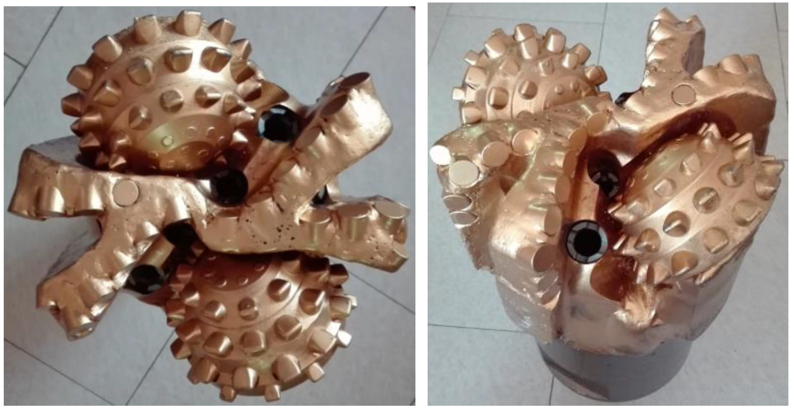
Figure 2-1.
Fracture and wear failure.
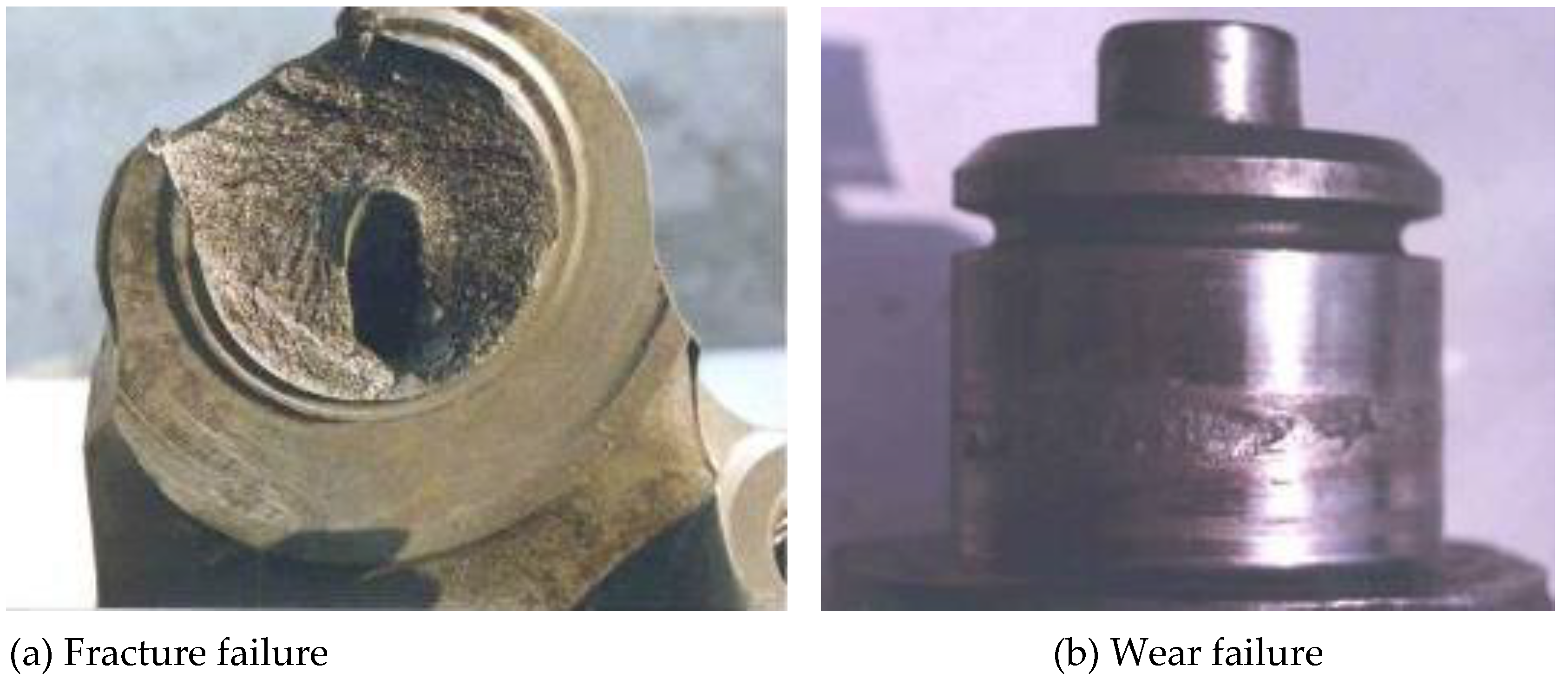
Figure 2-2.
Dangerous areas of bearing.
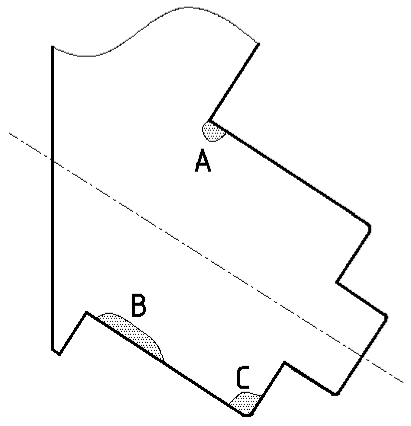
Figure 3.
Bilateral supporting bearing PDC-cone hybrid bit.
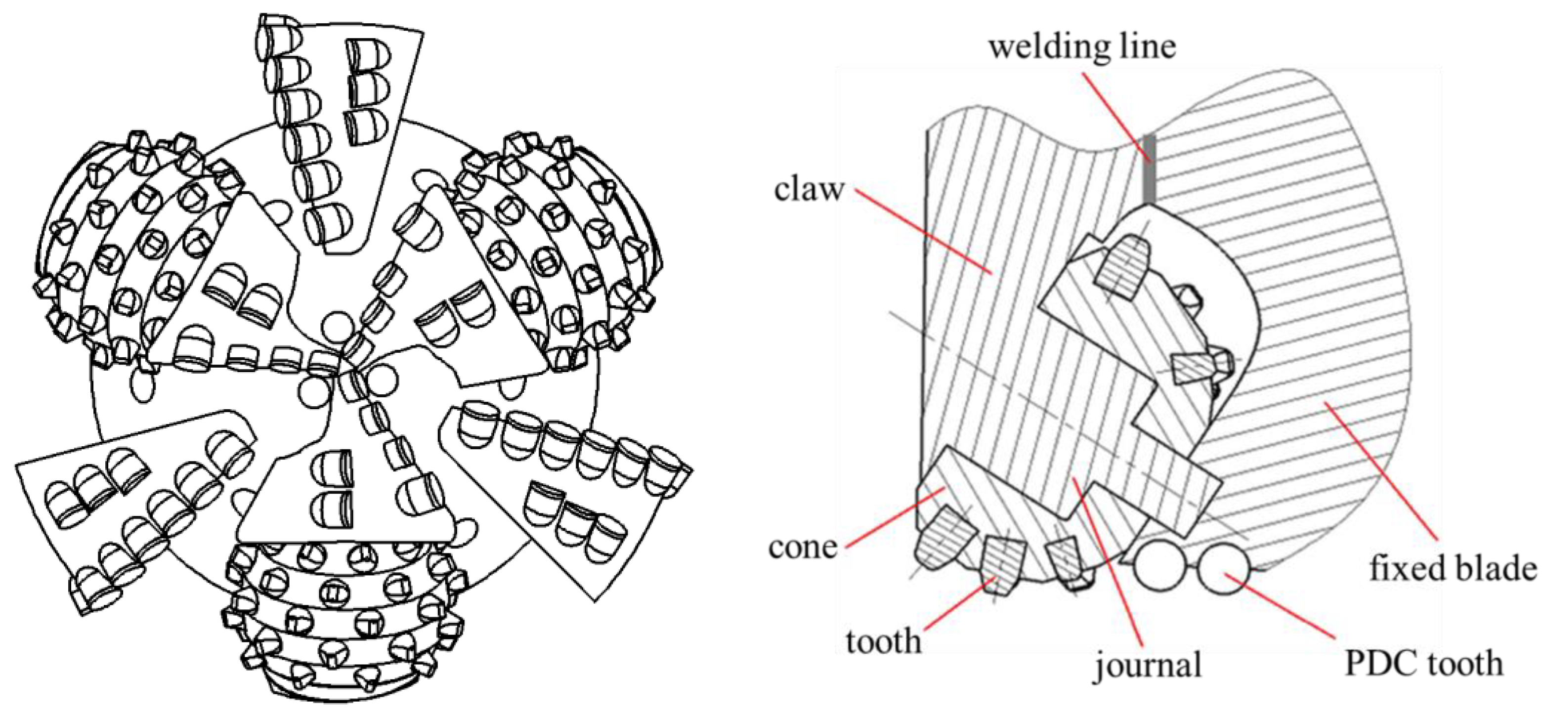
Figure 4-1.
Structural parameters of unilateral and bilateral support bearings.
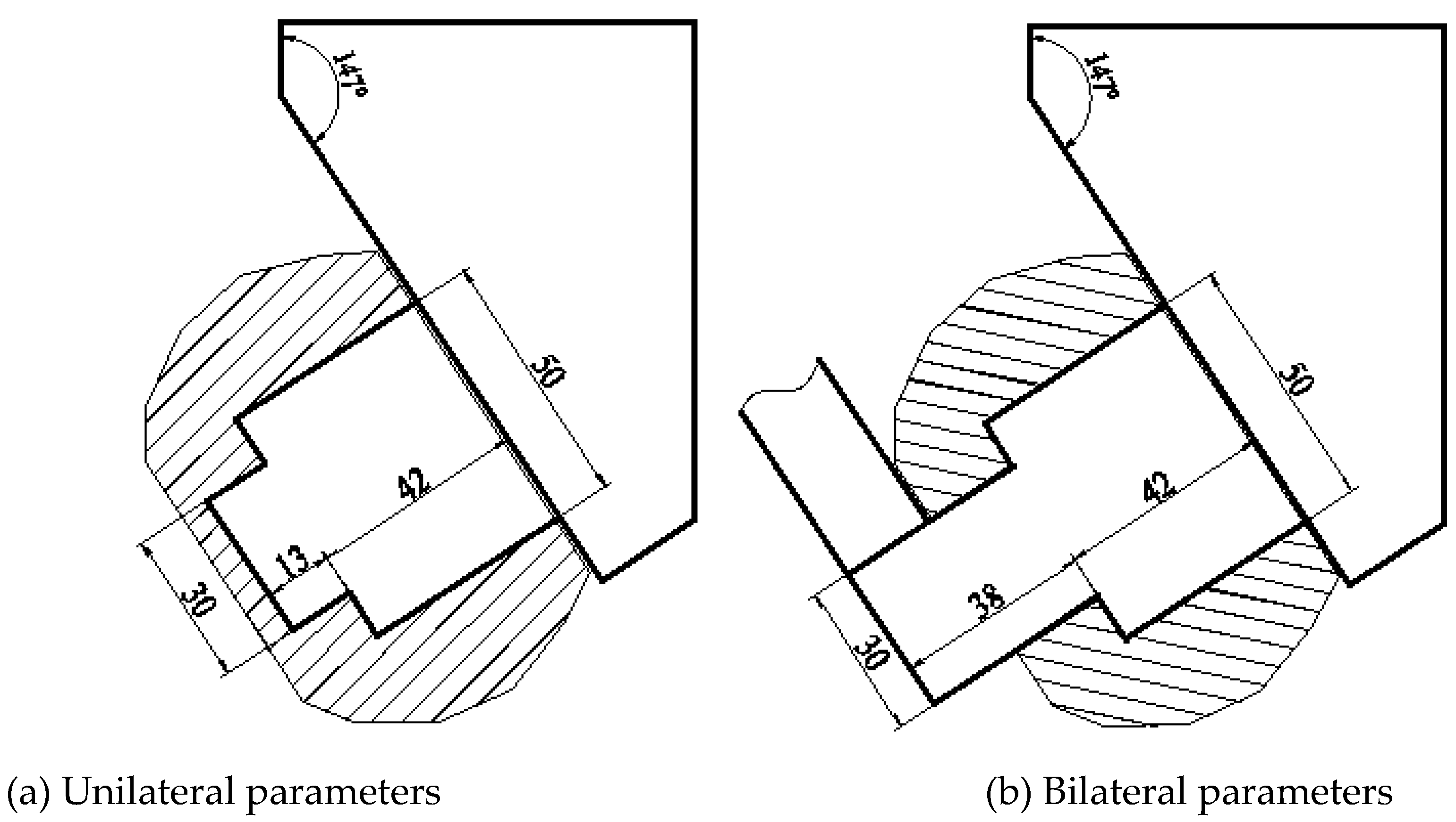
Figure 4-2.
Finite element model.
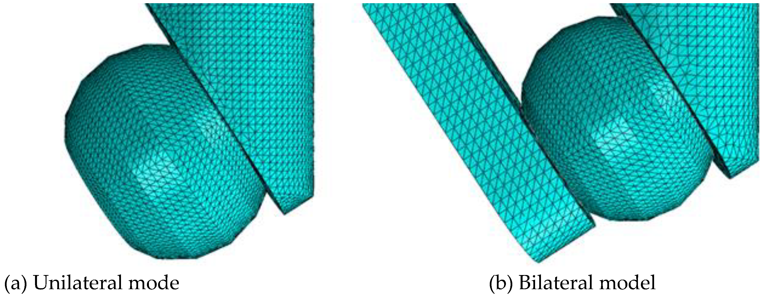
Figure 4-3.
Maximum Mises stress and stress distribution.
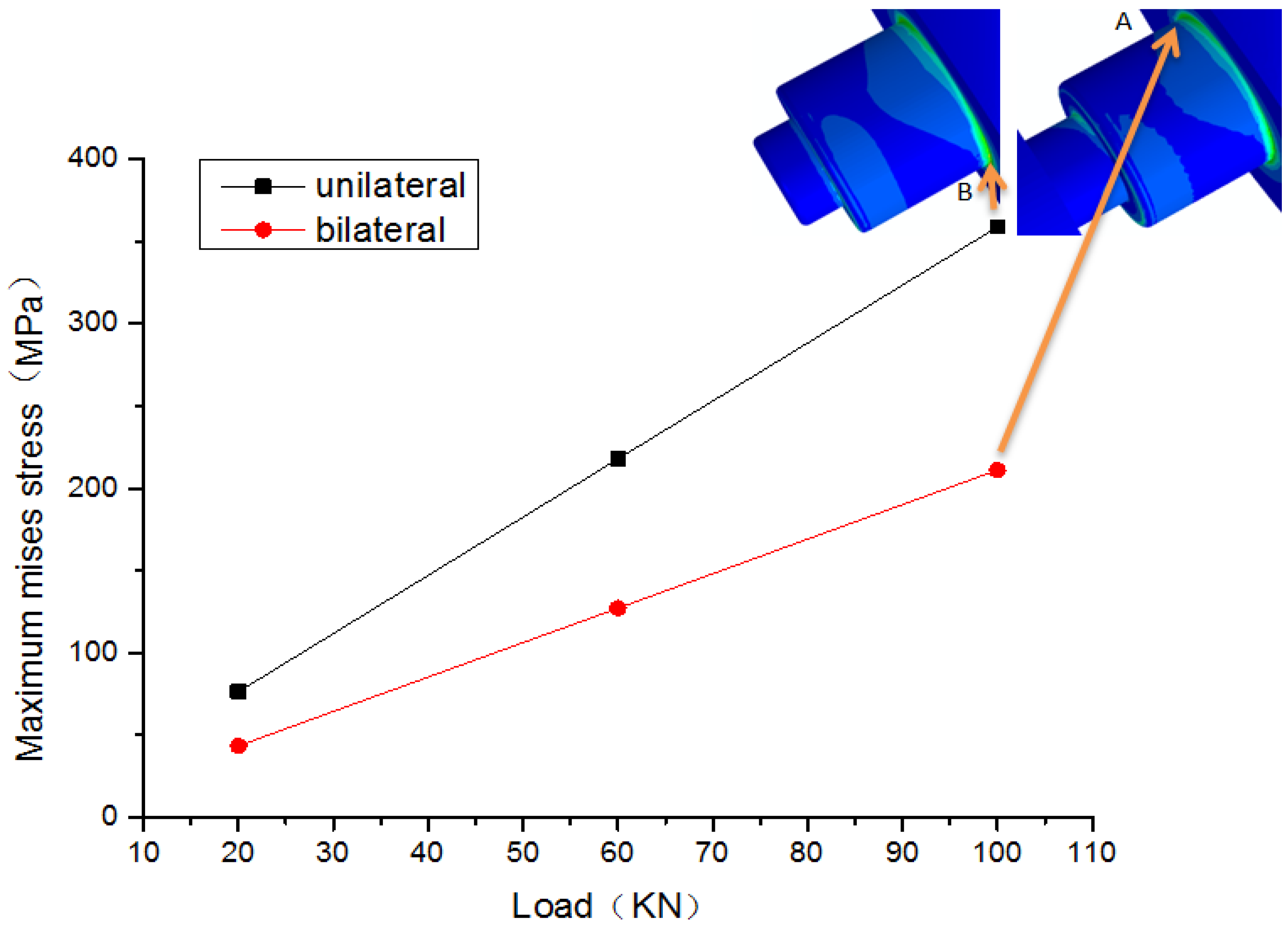
Figure 4-4.
Maximum contact stress and contact stress distribution.
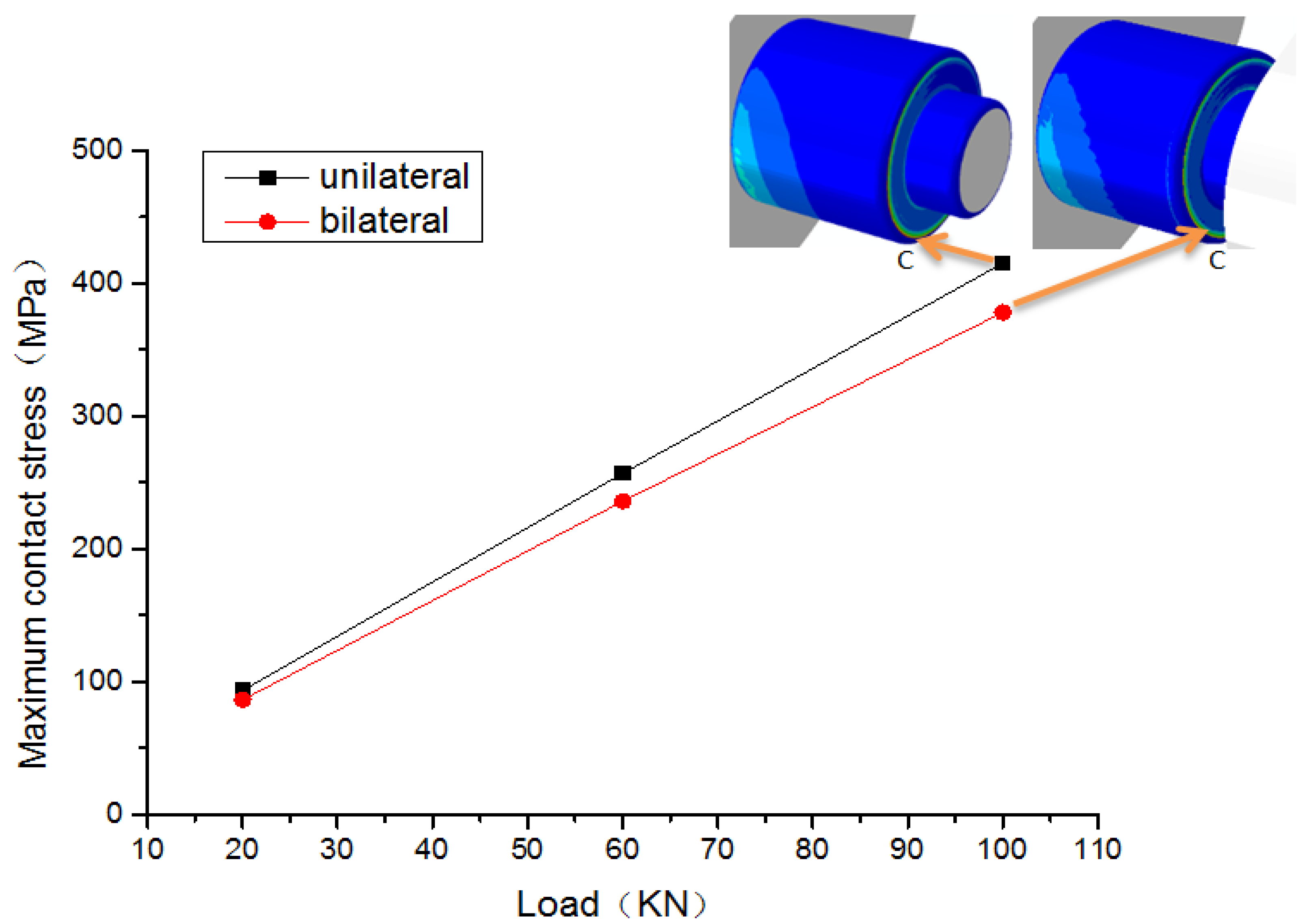
Figure 4-5.
Maximum principal strain and principal strain distribution.
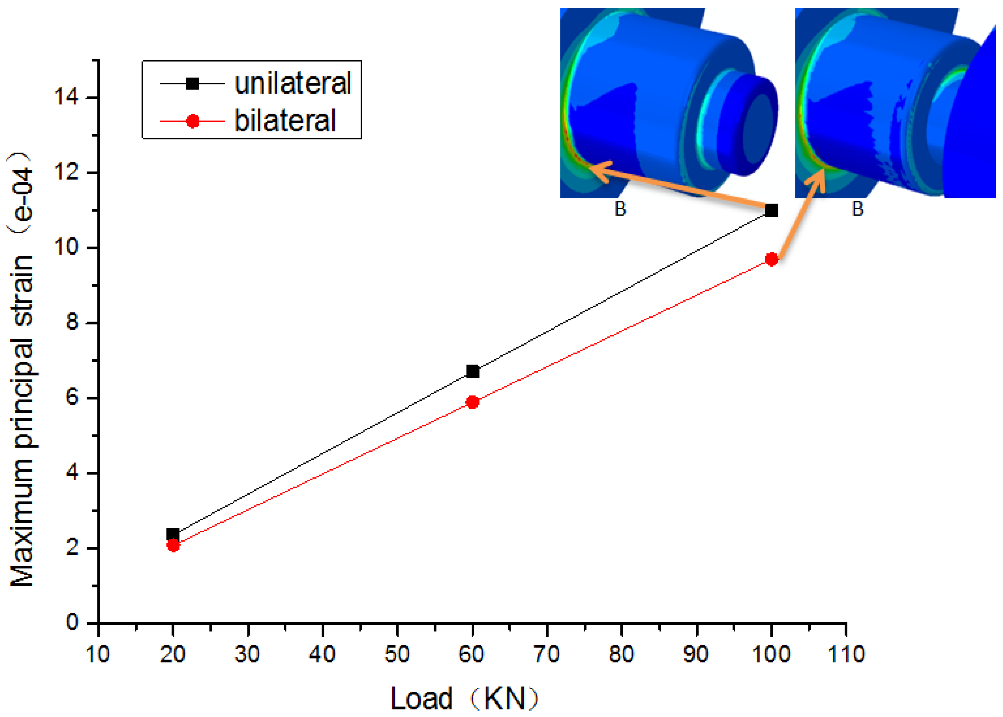
Figure 4-6.
Comparison of Mises stress, contact stress, and principal strain of A, B, and C zones at 100KN.
Figure 4-6.
Comparison of Mises stress, contact stress, and principal strain of A, B, and C zones at 100KN.
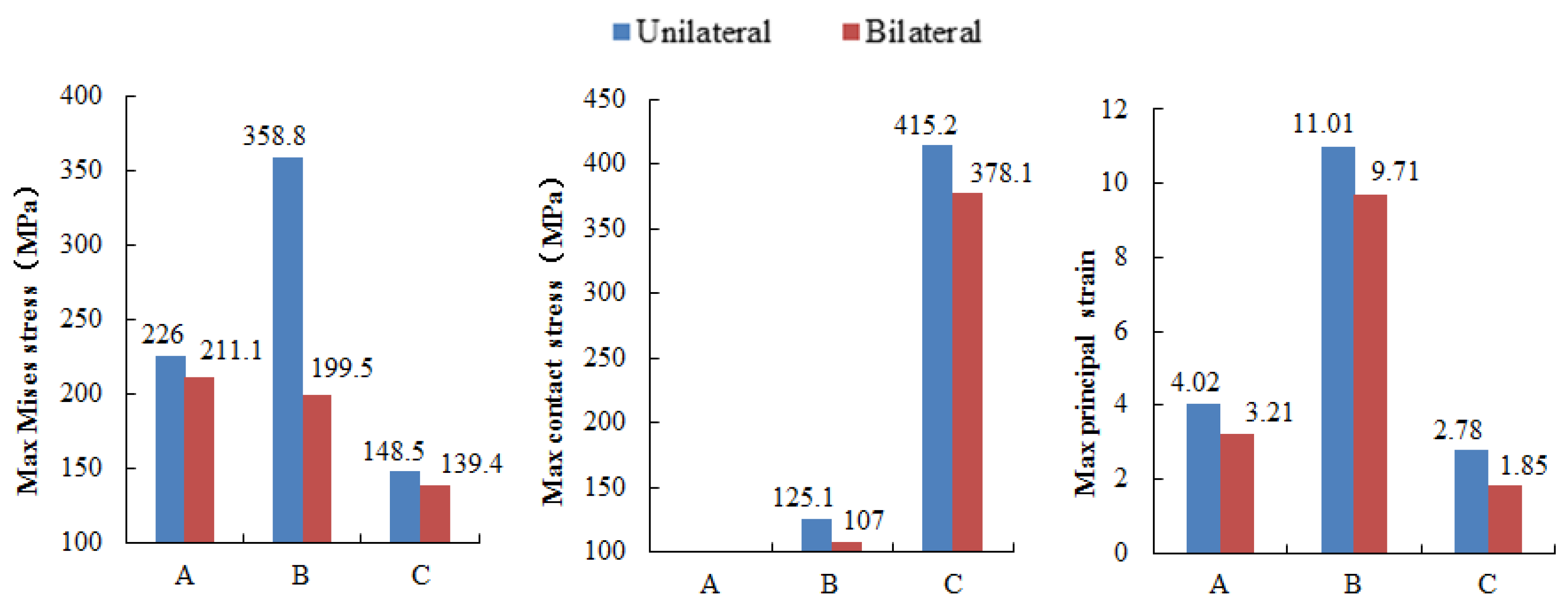
Figure 5-1.
Experimental principle of bearing strength.
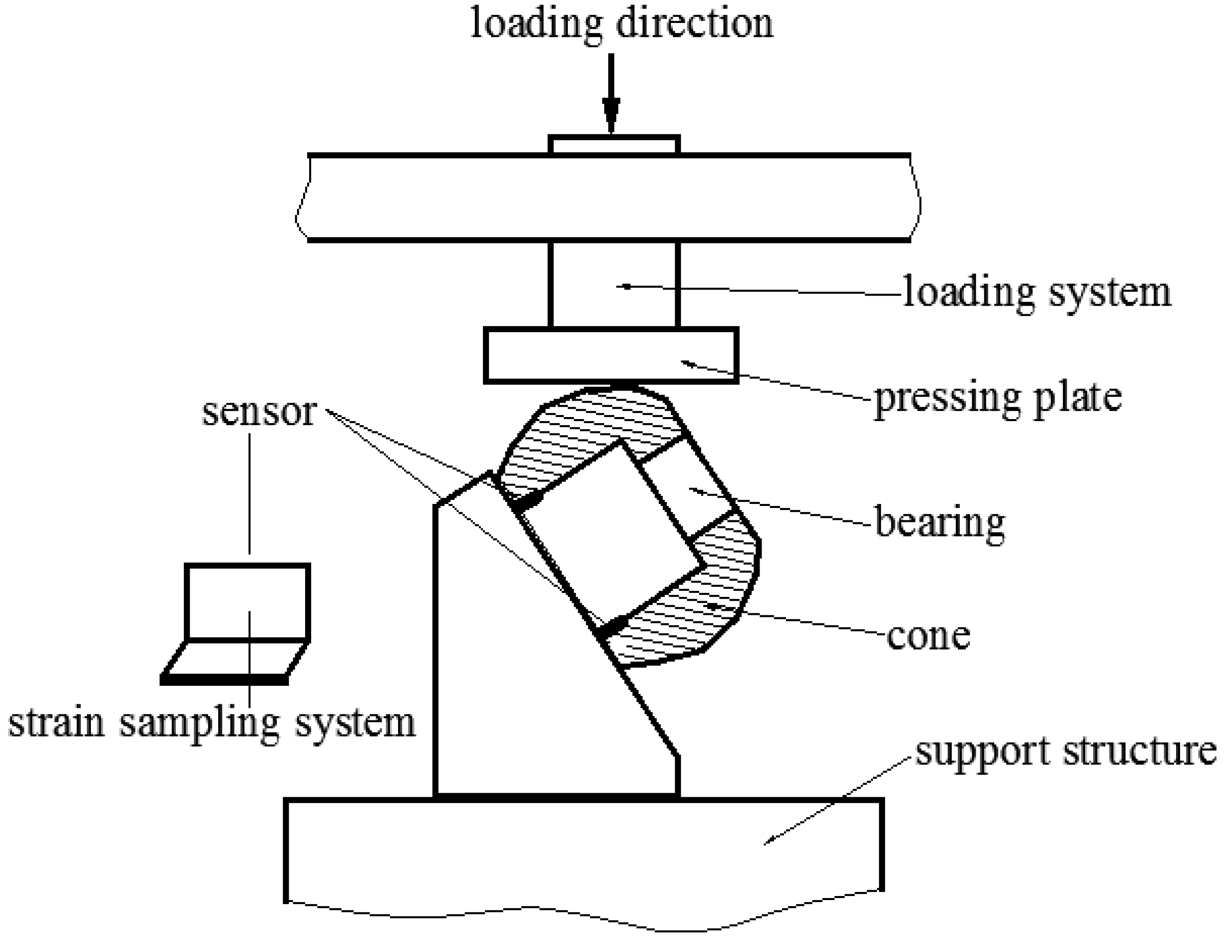
Figure 5-2.
Unilateral and bilateral bearing cone support structures.
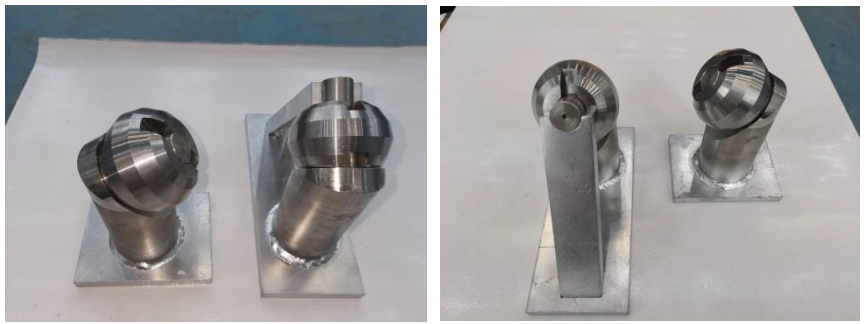
Figure 5-3.
DTD-500 structural mechanics experimental equipment.
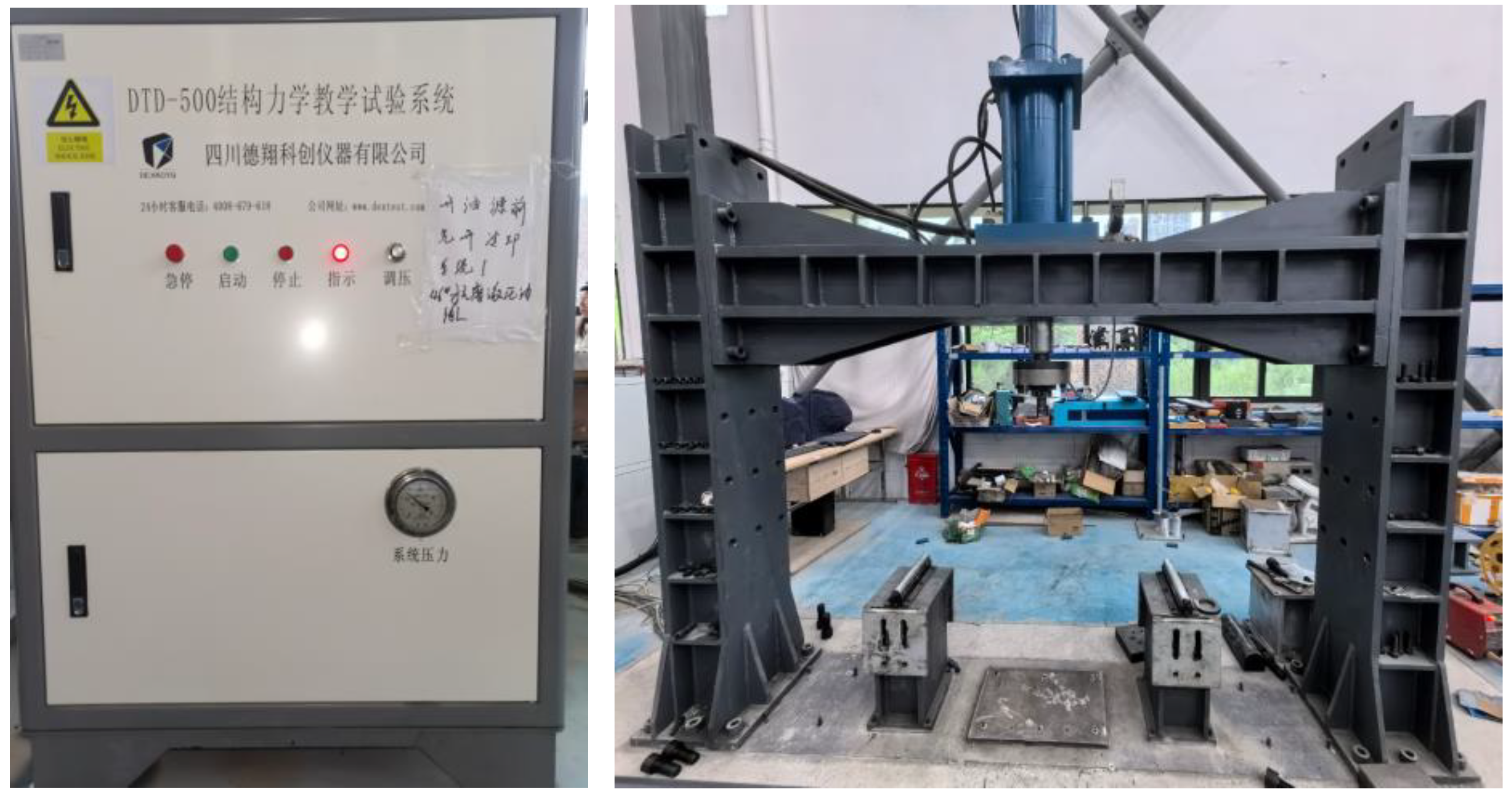
Figure 5-4.
Strain acquisition instrument and strain gauge.
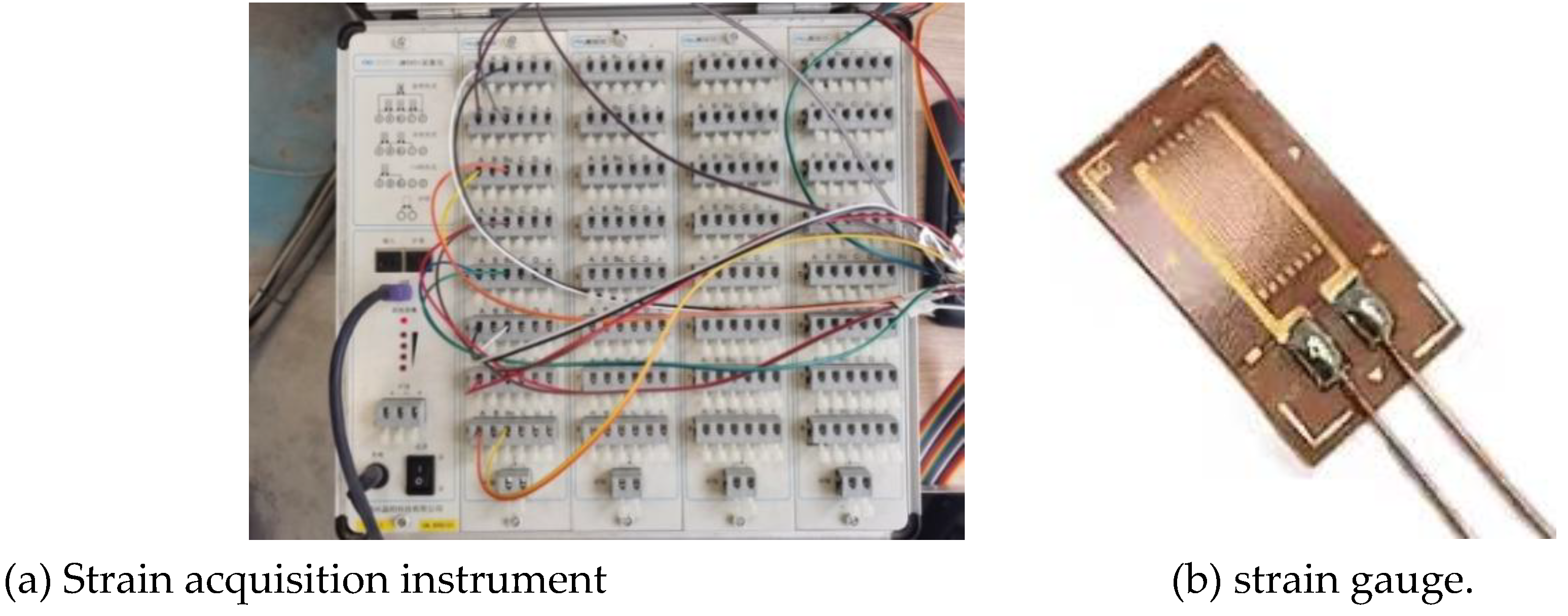
Figure 5-5.
Mounting strain gauge.
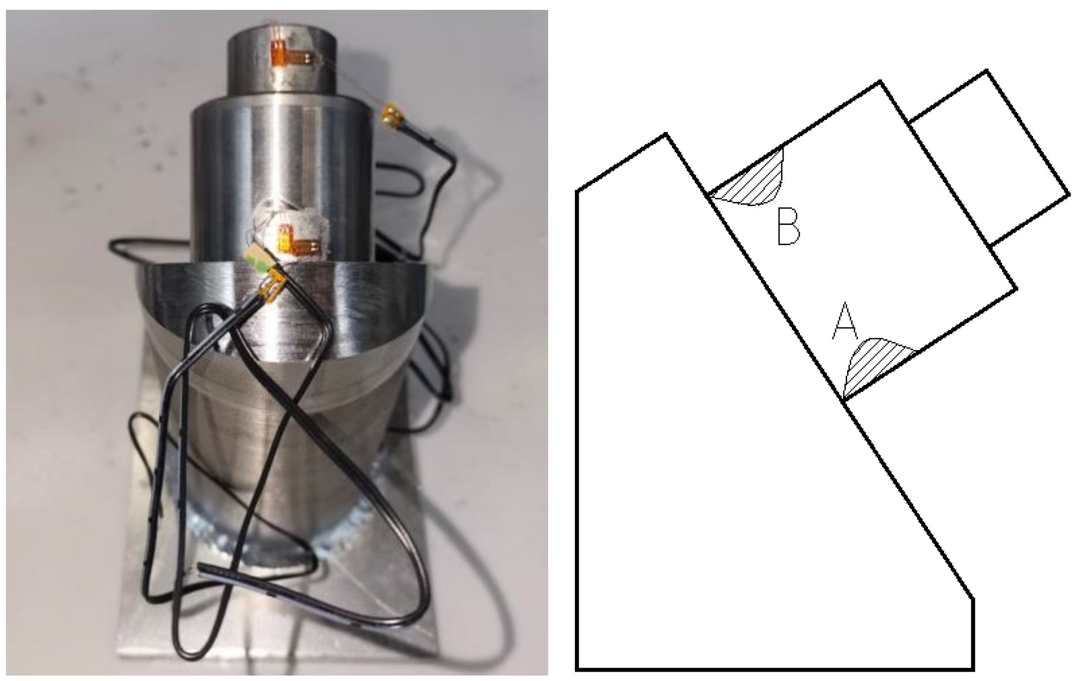
Figure 5-6.
Loading process.
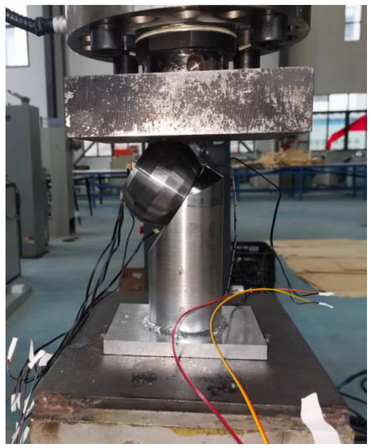
Figure 5-7.
Comparison of zone A、B strains of unilateral and bilateral support structure.
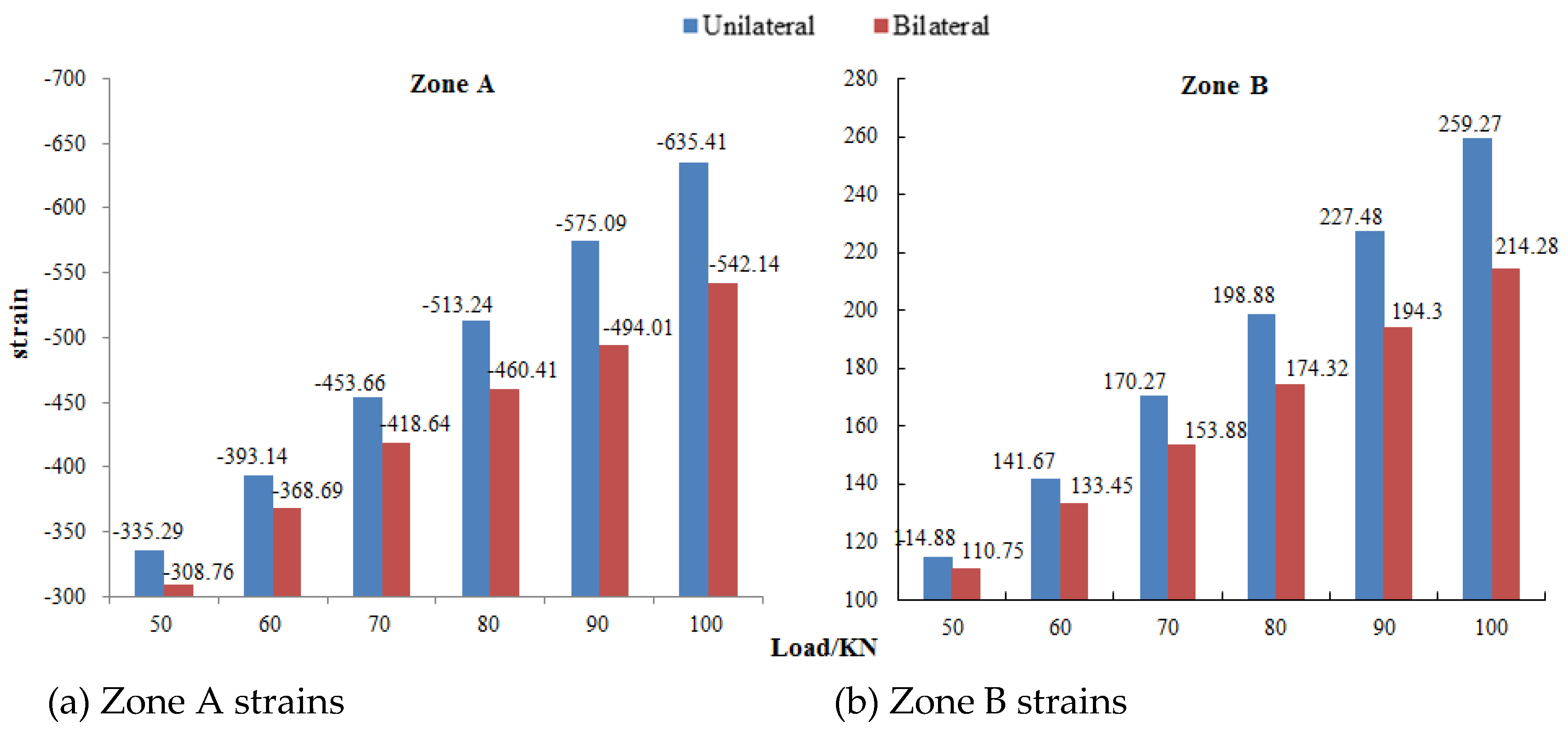

Table 4-1.
Structural parameters of unilateral and bilateral support bearings.
| Structure type | Large axis diameter (mm) | Large axis length (mm) | Small axis diameter (mm) | Small axis length (mm) |
| Unilateral | 50 | 42 | 30 | 13 |
| Bilateral | 50 | 42 | 30 | 38 |
Table 4-2.
Material properties of cone and claw.
| Name | Material | Modulus of elasticity (GPa) | Poisson ratio | Yield strength刘(MPa) | Density (kg/m3) | Tensile strength (MPa) |
| Claw | 20Cr刘NiMo | 208 | 0.3 | 785 | 7800 | 980 |
| Cone | 15Mn刘NiMo | 218 | 03 | 1035 | 8200 | 1423 |
Table 4-3.
Mises stress, contact stress, and principal strain of A, B, and C zones at 100KN.
| Stress | Unilateral | Bilateral | ||||
| Zone A | Zone B | Zone C | Zone A | Zone B | Zone C | |
| Max Mises stress (MPa) | 226.00 | 358.80 | 148.50 | 211.10 | 199.50 | 139.40 |
| Max contact stress (MPa) | 0.00 | 125.10 | 415.20 | 0.00 | 107.00 | 378.10 |
| Max principal strain | 4.02e-4 | 11.01e-4 | 2.78e-4 | 3.21e-4 | 9.71e-4 | 1.85e-4 |
Table 5-1.
Experimental plan.
| Structure type | Zones | Loading speed (KN/min) | Load (KN) | Number of test |
| Unilateral | A、B | 10 | 50, 60, 70, 80, 90, 100 | 3 |
Table 5-2.
Zone A、B strains of unilateral and bilateral support structure.
| Load/KN | Strain | |||
| Zone A | Zone B | |||
| Unilateral | Bilateral | Unilateral | Bilateral | |
| 50 | -335.29 | -308.76 | 114.88 | 110.75 |
| 60 | -393.14 | -368.69 | 141.67 | 133.45 |
| 70 | -453.66 | -418.64 | 170.27 | 153.88 |
| 80 | -513.24 | -460.41 | 198.88 | 174.32 |
| 90 | -575.09 | -494.01 | 227.48 | 194.30 |
| 100 | -635.41 | -542.14 | 259.27 | 214.28 |
Disclaimer/Publisher’s Note: The statements, opinions and data contained in all publications are solely those of the individual author(s) and contributor(s) and not of MDPI and/or the editor(s). MDPI and/or the editor(s) disclaim responsibility for any injury to people or property resulting from any ideas, methods, instructions or products referred to in the content. |
© 2024 by the authors. Licensee MDPI, Basel, Switzerland. This article is an open access article distributed under the terms and conditions of the Creative Commons Attribution (CC BY) license (https://creativecommons.org/licenses/by/4.0/).
Copyright: This open access article is published under a Creative Commons CC BY 4.0 license, which permit the free download, distribution, and reuse, provided that the author and preprint are cited in any reuse.


