Submitted:
02 August 2024
Posted:
06 August 2024
You are already at the latest version
Abstract
To date, the development of unmanned technologies using autonomous underwater vehicles (AUV) has become an urgent demand for solving the problem of inspection of industrial sub-sea structures. A key issue here is precise localization of AUVs relative to underwater objects. However, the well-known challenges of recognizing and coordinating underwater objects (impossibility to use GPS, undercurrents, etc.) do not allow high-precision navigation if based solely on a standard suite of AUV navigation tools (sonars, etc.). An alternative is a technology of processing of optical images that, at short distances, can provide higher accuracy of AUV navigation compared to a technology of acoustic measurement processing. In this study, in the context of the problem of subsea production system inspection, we propose a method to recognize underwater objects and provide coordinate reference of AUV to them, based on stereo-image processing. Its distinctive features are the use of a non-standard technique for generating a geometric model of an object from its views (foreshortening) taken from positions of a pre-made overview trajectory, the use of various characteristic geometric elements when recognizing objects, and the original algorithms for comparing visual data of the inspection trajectory with an a priori model of the object.
Keywords:
autonomous underwater vehicle (AUV)
; subsea production systems (SPS)
; computer vision
; stereo
; visual navigation
1. Introduction
The issue of inspection of underwater infrastructures (such as gas and oil pipelines, underwater mining systems, etc.) using autonomous underwater vehicles (AUV) [1,2,3,4,5], as an alternative to the previously deployed technology based on remotely operated underwater vehicles and divers’ operations, has become particularly relevant recently. Accurate positioning of AUV relative to such objects is a key problem of inspection.
However, the challenges in providing accurate AUV navigation in the underwater environment (the impossibility to use GPS, lack of terrain maps, insufficient accuracy of acoustic sensing, and limitations of optical sensing) prevent more extensive use of AUVs for solving inspection problems. Therefore, various tools and technologies are applied to improve navigation accuracy, depending on the tasks set for AUV mission, characteristics of scenes, and availability of primary data. The traditional equipment includes sonar navigation systems, Doppler lags, navigation and piloting sensors, and an Inertial Measurement Unit (IMU).
An integration of the standard suit of equipment with additional sensors is a frequent choice. For example, in the paper [6], the CView project is presented that addresses the problem of harbor inspection, and the methods for this are described. A scanning sonar is used for detecting obstacles and inspection targets. The sonar images are automatically processed by the edge detection and line extraction algorithms to get a simplified environment description, which is used by the guidance methods presented in that paper. A pan–tilt enabled sensor head with a camera, laser measurement, and a Multi Beam Echo Sounder are used to inspect the objects detected. Additionally, these sensors provide information about distance to the object being inspected which can be used by the inspection guidance.
The paper [7] reviews and analyzes the latest advances in integrated navigation technologies for AUVs and provides a comprehensive list of references for researchers who intend to apply AUVs to autonomous monitoring of aquaculture. Moreover, the paper [8] presents the current research trends in the field of AUVs. Applications of different sensor technologies like sonar, laser, acoustic modems, and stereo vision systems for localization, navigation and mapping are discussed.
An alternative to the above-mentioned navigation equipment is technologies based on processing of optical images taken with mono and stereo cameras. These methods can potentially provide higher accuracy of AUV navigation compared to processing of acoustic measurements in local scenes at short distances to objects. Several groups of applications can be considered here:
The study [9] presents an integration of two different stereo visual odometry algorithms into an AUV and the experiments carried out under laboratory and harbor conditions with comparing vision-based pose estimates with ground truth.
In [10], a method for localizing AUVs using visual measurements of underwater structures and artificial landmarks is described.
In a number of studies, e.g., in [11,12], methods to track the desired trajectory using visual measurements of points features and adaptive control, including neural networks, are considered.
In [13], a vision guidance method is applied to send an AUV home to the dock station.
In [14], a method for monocular visual odometry with optical flow tracking is proposed, which, according to the authors, is more suitable for underwater imaging than the classic approaches based on descriptors.
The issue of determination of vehicle’s position relative to the objects being inspected is based on solving the problem of object recognition. Since primarily industrial sub-sea structures are considered here, it is advisable to take into account the geometric specifics of artificial objects (the evident presence of standard geometric elements in its shape).
The paper [15] addresses the problem of object recognition from colorless 3D point clouds in the underwater environments. It compares the performances of the state-of-the-art methods for underwater object recognition (global descriptors). The studied methods are designed to assist AUVs in performing autonomous interventions in underwater Inspection, Maintenance and Repair (IMR) applications. In that paper, a number of methods based on analysis of surface characteristics of the object are considered [16,17,18,19].
In [20] the authors develop their previous study by proposing a 3D object recognition method for non-colored point clouds using point features. The method is designed for application of scenarios such as IMR of industrial sub-sea structures composed of pipes and connecting objects (such as valves, elbows, and R-Tee connectors). The recognition algorithm uses a database of partial views of the objects, stored as point clouds, which is available a priori.
When developing inspection technologies, preliminary information about the objects can be taken into account such as digital maps of the area [21] or availability of coordinate measurements of characteristic point features of the objects in the external coordinate system (CS) [22].
An interesting solution to inspection issues was proposed in [23]: an unmanned method where an AUV performs inspection tasks being coupled with an Unmanned Surface Vessel.
In this article, we propose a new approach to addressing the problem of underwater object recognition and coordinate referencing of AUV to them within the framework of inspection of subsea production system (SPS). The approach is based on the non-standard automated technique for forming a geometric model of the object based on images of an overview trajectory, the use of different types of characteristic geometric elements in object recognition, and the application of original algorithms for matching the obtained visual data with an a priori model of the object.
The article is structured as follows. Introduction provides a review of available information as regards the issues addressed in the article. Section 2 briefly considers the proposed approach to solving the problem of coordinate reference of the AUV to the SPS. Section 3.1 describes a technique to form a model of SPS object on the basis of views of the overview trajectory. Section 3.2 describes algorithms for recognizing the characteristic geometric elements in a stereo-pair of frames at the position of the AUV’s working trajectory that provide identification of the SPS object and calculation of AUV’s movement in the coordinate space of the object. Section 4 presents the results of experiments with synthetic and actual data. Section 5 is devoted to the discussion of the results of the work.
2. Problem Statement and General Approach
The problem of regular IMR of various underwater engineering facilities, including subsea production system (SPS), requires precise coordinate reference of the AUV to underwater artificial objects during inspection missions. Referencing the AUV to the object’s coordinate system (CS) is necessary for planning the AUV trajectory and performing operations (photography of critical structural components, possible landing and repair) directly in the coordinate space of the objects under inspection. It is assumed that the AUV, along with the standard suite of navigation sensors, is equipped with an optical stereo camera directed strictly down relative to the AUV longitudinal axis. In the context of this issue, the problem of calculating the exact coordinate reference of the AUV to the CS of a sub-sea artificial object is solved using video information. Structurally, SPS is defined as a set of functionally integrated objects distributed over a limited area of the seabed and coordinated in the CS of SPS. When the AUV is moving along the specified trajectory in the area of the SPS location, regular attempts are made to identify the SPS objects by processing the stereo video stream from a camera. Recognition of the object under inspection is performed by comparing the geometric information derived from stereo images to the a priori specified 3D model of the object. Hereinafter, the term “object model” means a visual model, i.e., a set of spatial elements of the object visible through the camera. The visual model may not match the functional model of a large object that describes this object at the level of its certain functional units. Nevertheless, the visual model elements may have attributes indicating that they belong to certain functional units of the object, if necessary for inspection purposes. The model is built with the involvement of the operator. Unlike the traditional technique, where the model is formed based on in situ measurements or documentary information describing the object, the proposed technique uses images of a few views of pre-made overview trajectory of the AUV and 3D information obtained on their basis. The overview trajectory is set in such a way that the camera could capture images of all objects (or parts of the object, if it does not completely fit into the camera’s field of view due to its large size) of the distributed SPS. Then, we define SPS model as a combination of models of all objects composing the SPS. Also, we define model of a certain object as a combination of models of all used object’s views from the overview trajectory. The model of a certain view is a set of 3D geometric elements of the object (visible from this aspect) that characterize the spatial structure of its visible part. Stereo-pairs of frames of the views that were used to build the object model are linked with it. The characteristic 3D point features of the object and rectilinear segments and macro-elements composed of segments characterizing the shape of the object are considered as geometric elements of the model. According to the technique, the operator, based on a visual analysis of the overview trajectory images used and the calculated 3D data, forms characteristic elements (CEs) for each view. CEs are coordinated both in the CS linked with a specific view and in the object’s intrinsic CS built by the operator. For each used view of the overview trajectory, a coordinate transformation matrix is calculated, linking the CS of this view with the object’s intrinsic CS. The matrix is formed by the well-known technique: by specifying the unit vectors of the object’s CS in the view’s CS. One of the objects’ CSs is fixed as a CS of SPS. Accordingly, a coordinate transformation matrix is formed for each object, linking the object’s CS with the CS of SPS.
The use of several views of the object and CEs of different types increases the reliability of identification of certain objects and the accuracy of AUV navigation relative to the underwater object.
The object identification and the coordinate referencing of AUV to the object’s intrinsic CS is generally performed by a sequential three-stage computational scheme. At the first stage, direct recognition of 3D point features of the object is made from a stereo-pair of frames taken by the AUV camera at the analyzed position of the working (inspection) trajectory. This is done using the algorithm for matching the set of point features in the stereo-pair of frames of the working trajectory with the set of point features in the stereo-pair of the model (for each used view of the overview trajectory) (see the description of the algorithm in section 3.2.1). The result of the matching algorithm is two matched sets of 3D points, of which one is determined in the model’s CS and the other in the camera’s CS at the position of the working trajectory (in the AUV’s CS). The matrix for coordinate transformation between the AUV’s CS and the CS of the object model is calculated using these two matched 3D sets. The resulting coordinate transformation matrix can be considered as an acceptable solution to the problem of AUV referencing to the object, or be used as an initial approximation when obtaining a more reliable and accurate solution at the second and third stages, taking into account all types of CEs.
At the second stage, rectilinear segments and macro-elements are recognized using the coordinate transformation matrix obtained at the first stage. Note that this approach does not involve the vectorized shapes of source images (which require significant computational costs); however, correlation estimates are used when comparing the segment line images in the model and in the working stereo-pair of frames. Recognition of elements additional to points increases the reliability of object identification and the accuracy of coordinate reference to them.
At the third stage, an updated matrix of coordinate transformation from the CS of the AUV’s working trajectory position to the object’s CS is calculated with the point data for all views and CE types taken into account.
3. Methods
It is advisable to plan and perform the AUV inspection trajectory in the coordinate space of an subsea production system (SPS) or a separate object inspected. Therefore, when the AUV is moving along the working trajectory, SPS objects are searched/detected using the methods and algorithms based on comparison of the geometric information derived from recorded stereo frames to the object models. Thus, the problems of detection of 2D characteristic elements in images, 3D reconstruction of CEs, and matching of spatial CEs with the object model are solved sequentially. Models of SPS objects are formed by an automated technique based on photographs of the overview trajectory using several views (aspects). Three types of CEs are considered as spatial elements of an object model: point features, rectilinear segments and, possibly, macro-elements built on a combination of segment lines. In this study, geometric elements of a “corner” type are considered as macro-elements. Eventually, the problem of calculating the AUV’s movement in the CS of a subsea object is solved.
Below, the following designations are used:
M_2D_POINT_VkVk_LR and M_2D_ POINT_VkVk_RL are matched sets of points in the left and right frames of the “model” stereo-pair of the kth view (recall that the model is considered as a set of several used views of the AUV’s overview trajectory). Here, the symbol “M” means that the set belongs to the model, and the symbol “S” will be used in the identifiers of sets belonging to the frames of the “working” stereo-pair. Vk indicates that the kth view of the overview trajectory is used. The LR mnemonics means that the set in the left frame of the stereo-pair is matched to the set in the right frame of the stereo-pair. The RL mnemonics are used in a similar way. The designation VkVk below means that the matching refers to the stereo-pair of frames of the kth view. Similarly, the mnemonics of the WW designation mean that the sets belonging to the frames of a “working” stereo-pair are matched. The designation VkW means that the set in the frames of the working stereo-pair is matched with the set of the model of the kth view (the kth view of the overview trajectory). Accordingly, the designation WVk means that the set of the model of the kth view is matched with the set in the frames of the working stereo-pair. The sets belonging to the object model are formed using an automated technique with the involvement of the operator.
CSview_k – the coordinate system of AUV’s camera for the kth view of the overview trajectory.
CSwork – the coordinate system of AUV’s camera at the considered position of the working (inspection) trajectory.
CSobject_n – the coordinate system of the nth object of SPS.
CSSPS – the coordinate system of SPS (CS of one of the objects can be selected as CS of SPS).
M_3D_POINT_VkVk_CSview_k – a set of 3D points in the coordinate system CSview_k (belongs to the 3D model of the kth view of the overview trajectory) obtained from the matched sets M_2D_POINT_VkVk_LR and M_2D_POINT_VkVk_RL.
M_3D_LINE_VkVk_CSview_k – a set of 3D “segment lines” in the coordinate system CSview_k (part of a 3D model for the kth view of the overview trajectory).
M_3D_CORNER_ VkVk _CSview_k – a set of 3D “corners” in the coordinate system CSview_k (part of a 3D model for the kth view of the overview trajectory).
M_2_POINT_WVk_LL and S_2D_POINT_VkW_LL – 2D sets of points matched (using the SURF detector). The first set is determined in the left frame of the “model” stereo-pair of the kth view; the second set, in the left frame of the “working” stereo-pair.
subM_2D_POINT_Vk Vk and subS_2D_ POINT_WW – 2D subsets of points matched.
The first subset is the intersection of the sets M_2D_POINT_VkVk_LR and M_2D_POINT_WVk_LL in the left frame of the “model” stereo-pair of the kth view; the second subset is the intersection of the sets S_2D_POINT_WW_LR and S_2D_POINT_VkW_LL in the left frame of the “working” stereo-pair.
M_3D_POINT_Vk_CSview_k – a subset of 3D points of the model of the kth view (in CSview_k) to which the subset of recognized points S_3D_POINT_Vk_CSwork (being part of the set S_3D_POINT_WW_CSwork) is matched.
M_3D_LINE_Vk_CSview_k – a subset of 3D segment lines of the model of the kth view (in CSview_k) to which the subset of recognized segment lines S_3D_LINE_Vk_CSwork (being part of the set S_3D_LINE_WW_CSwork) is matched.
M_3D_CORNER_Vk_CSview_k – a subset of 3D corners of the model of the kth view (in CSview_k), to which the subset of recognized corners S_3D_CORNER_Vk_CSwork (being part of the set S_3D_CORNER_WW_CSwork) is matched.
M_3D_POINT_Vk_ CSobject_n, M_3D_LINE_Vk_ CSobject_n, M_3D_CORNER_Vk_ CSobject_n – the same above-listed sets of recognized CEs of three types belonging to the kth view, but coordinated in the object’s CS (CSobject_n).
M_3D_POINT_CSobject_n – a combined set of objects’ 3D points, recognized for all views used, at the considered position of the working (inspection) trajectory.
M_3D_LINE_CSobject_n – a combined set of objects’ 3D segment lines, recognized for all views used, at the considered position of the working (inspection) trajectory.
M_3D_CORNER_CSobject_n – a combined set of objects’ 3D corners, recognized for all views used, at the considered position of the working (inspection) trajectory.
S_2D_ POINT_ WW_LR and S_2D_POINT_WW_RL – matched sets of points in the left and right frames of the “working” stereo-pair. These sets are generated and matched using the SURF detector.
S_3D_POINT_WW_CSwork – a set of 3D points in the coordinate system CSwork obtained from the matched sets S_2D_POINT_WW_LR and S_2D_POINT_WW_RL.
S_3D_POINT_VkW_CSwork – a subset of the 3D “points” recognized in the working stereo-pair of frames when compared to the kth view, coordinated in CSwork (np_k is the number of points in the subset for the kth view) (being part of the set S_3D_POINT_WW_CSwork). The subset is matched to the subset of the model M_3D_POINT_Vk_CSview_k.
S_3D_LINE_VkW_CSwork – a subset of the 3D “segment lines” recognized in the working stereo-pair of frames for the kth view, coordinated in CSwork (nl_k is the number of segment lines in the subset for the kth view).
S_3D_CORNER_VkW_CSwork – a subset of the 3D “corners” recognized in the working stereo-pair of frames for the kth view, coordinated in CSwork (nc_k is the number of corners in the subset for the kth view).
S_3D_ POINT_CSobject_n – a set of “points” in CSobject_n obtained by combining the recognized “points” across all views.
S_3D_LINE_CSobject_n – a set of “segment lines” in CSobject_n obtained by combining the recognized “segment lines” across all views.
S_CORNER_CSobject_n – a set of “corners” in CSobject_n obtained by combining the recognized “corners” across all views.
HCSwork, CSview_k – a matrix for coordinate transformation from the CS of the AUV’s inspection trajectory position into the CS of the kth view of the overview trajectory.
HCSview_k, CSobject_n – a matrix for coordinate transformation from the CS of the kth view of the overview trajectory into the CS of the nth object.
HCSwork, CSobject_n – a matrix for coordinate transformation from the CS of the AUV’s inspection trajectory position into the CS of nth object.
HCSobject_n, CS_SPS – a matrix for coordinate transformation from the CS of nth object into the CS of SPS.
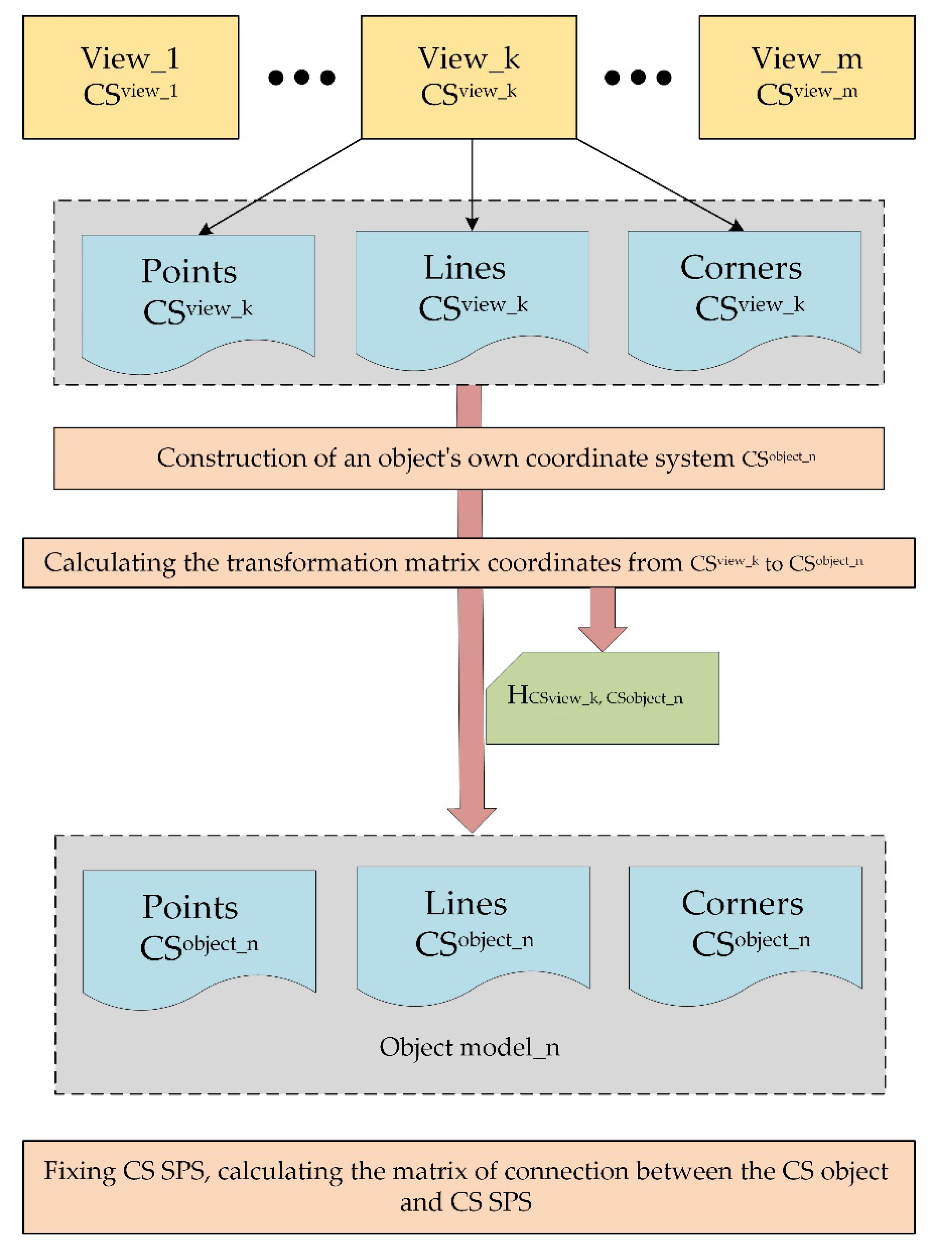
Figure 1.
Forming an object model based on overview trajectory images.
3.1. Forming the Model Object
Geometric models of SPS objects are formed at a preliminary stage, prior to launching inspection missions. These are used to visually recognize SPS objects and provide coordinate referencing of AUV to them during each of the subsequent inspection missions. The model is usually formed using direct measurements of characteristics of the object/SPS with the involvement of documentary information and/or using software tools. Point features are often used as characteristic features determining the spatial geometric structure: points generated and matched in stereo-pair of frames using the SURF detector or corner points [24] presumably recognized using the Harris Corner Detector on the basis of images taken by the AUV camera during inspection. The advantage of this technique for object identification is its versatility: it does not require the shape of the surface to be taken into account. However, using point features only (when matched with the model) may not be enough to reliably identify the object because (a) point features do not fully reflect the spatial geometric structure of the object, and (b) the possibly small number of matched points (since photography from the overview trajectory and from the working one is conducted under different conditions, i.e., at different altitudes, at different angles, and in different illuminations) may reduce the accuracy of referencing the AUV to the object. To increase the reliability of object identification and the accuracy of AUV’s coordinate reference to the object, it is suggested, first, to use CEs of the “point” type from all views used, and then to use segment lines and macro-elements based on them, along with points, as characteristic features of the object. For example, such elements as “corner” type (a vertex with the adjacent sides, segment lines) are more reliably recognized. In particular, corner is remains unchanged under varying illumination and external effects on the object (corrosion, algae fouling, etc.). Second, an automated method for forming an object model is proposed, aimed at improving the efficiency of object recognition when AUV performs a working mission. On the one hand, the method excludes preliminary direct in situ measurements, and, on the other hand, it contributes to a higher degree of object recognition at the stage of inspection. The essence of the automated technique is to involve the operator in constructing an object model based on processing the results of video records from the pre-made overview trajectory of the AUV. The operator can clearly indicate the CEs forming the object model, which, presumably, will be well recognized by the AUV moving along the inspection trajectory. When indicating CEs, the operator uses source images and auxiliary software and algorithmic tools in an interactive mode (the SURF detector, the ray triangulation method, the visual navigation method (VNM) [23], 3D visualization, and necessary interactive service). The overview trajectory is planned in such a way that the set of its used views provides a good overview of all the SPS objects to be inspected. The operator forms the object’s intrinsic CS in which the spatial model of the object should be described, which is necessary for accurately setting the trajectory of the inspection mission at the planning stage. For each used view of the object, a matrix is calculated linking the CS of this view with the object’s CS. By means of these matrices, the coordinates of all the CEs of all the views used are transformed into the object’s CS and stored in the respective sets representing the complete 3D model of the object (with all the used views taken into account). Also, for each SPS object, the matrix to link the CS of this object with the CS of SPS is calculated, for which the CS of one of the objects is used.
The main steps of the method for object model formation are shown in Figure 1:
- The operator selects one or more the most informative object’s views from the sequence of photographs of the overview trajectory (with respective stereo-pairs of frames), which together can potentially provide recognition of the object for any position of the working (inspection) trajectory when the AUV is positioned above the object.
- The operator fixes a rectangular area of the object’s location in the seabed plane (using the VNM, which provides calculation of points’ coordinates in the external CS with some accuracy). This allows for a rough object search at the recognition stage (while the AUV is moving along the working trajectory) before activation of the object recognition algorithm based on processing of images taken with the camera.
-
The operator creates a 3D model of the object that combines the 3D models of several used views of the overview trajectory. The spatial geometric elements making up the model are formed through processing the original stereo-pairs of frames of the views used. The processing includes the application of algorithmic procedures with the explicit involvement of the operator in the process of CEs formation. The types of elements used, as noted above, are as follows: points, rectilinear segments, and macro-elements based on segment lines (such as “corner” type or others). For each selected kth view of the AUV’s overview trajectory:
- The point features in the left and right frames of the stereo-pair are matched using the SURF detector. The points belonging to the object, specified by the operator, are filtered and selected. Manual generation of additional points is possible. It is also possible to include terrain points nearby the object, since the scene is static. By matching the sets of points M_2D_POINT_VkVk_LR and M_2D_POINT_ VkVk_RL, a set of 3D points M_3D_POINT_ VkVk_CSview_k, visible through the camera for this view, is constructed using the ray triangulation method. The points are coordinated in the CSview_k of this view of the overview trajectory.
- The operator generates a set of 3D edge lines visible through the camera in CSview_k of this view using the original frames of the stereo-pair. Each spatial segment line is described by two 3D endpoints belonging to it with pointers at 2D images of these points in the 2D sets indicated above. The problem of 3D reconstruction of the matched 2D images of segment lines in the model stereo-pair of frames is solved in a traditional way: by matching the endpoints in the stereo-pair of frames with calculation of correlation estimates when scanning epipolar lines and then calculating the 3D coordinates of the segment endpoints in CSview_k by the ray triangulation method. The endpoints can also be matched by the operator clearly indicating the matched images. The formed segments are coordinated in CSview_k and stored in the set M_3D_LINE_ VkVk_CSview_k.
- 3.3. Formation of “corner” type CEs based on the set of spatial segments obtained for this view. The formed CEs “corners” are coordinated in the CSview_k and stored in the set M_3D_CORNER_ VkVk_CSview_k.
- To obtain a model description independent of the AUV’s CS, the operator explicitly determines the object’s intrinsic CS. Such a CS is determined on the basis of the segment line indicated by the operator (let it be referred to as base segment line) in such a way that the Z'-axis is oriented in the direction of the Z-axis of the external CS (see Figure 2). This can be done using the data received by the standard navigation system of the AUV. For each used kth view of the object, a coordinate transformation matrix is calculated that links the object’s CS with the CS of the camera of this view of the overview trajectory (which is done in a standard way by setting the unit vectors of one CS in the other CS). If the camera does not see the selected base segment line in one of the views, then the VNM method is applied, which provides a matrix for coordinate transformation from the CS of one trajectory position into the CS of the other position (i.e., the coordinates of the base segment line are calculated in the CS of the considered view implicitly, without matching in the stereo-pair of frames). Afterwards, the object’s intrinsic CS is built, the same as for other views, on the base segment line, and the matrix of link between the CS of this view and the object’s CS is calculated. Thus, a single CS of the object is built by using the same spatial base segment line in all the views used. For each kth view, its own matrix HCSview_k, CSobject_n of transformation into this object’s CS is calculated (where n is the object’s sequential number).
- The coordinates of all three CE types of the used kth view are transformed using the calculated matrix into the object’ intrinsic CS built. The obtained coordinate representations are stored, respectively, in the sets M_3D_POINT_Vk_CSobject_n, M_3D_LINE_Vk_CSobject_n, and M_3D_CORNER_Vk_CSobject_n specified in CSobject_n. Simultaneously, these coordinate representations are recorded to the respective accumulated sets representing the object’s complete 3D model in CSobject_n with all processed views taken into account: M_3D_POINT_CSobject_n, M_3D_LINE_CSobject_n, and M_3D_CORNER_CSobject_n. Note that, if CE is present in several views, then in the complete model it is represented by averaged coordinates.
- The operator explicitly determines the CS of SPS. As such a CS, the CS of one of the objects is used. The intrinsic CSs of all objects are coordinated in the CS of SPS.
Thus, the object model is formed in two representations:
- as a set of models of several object’s views, where the model of a view is a combination of three CE sets (points, lines, and corners) specified in the CS of this view (CSview_k). The matrix HCSview_k, CSobject_n for coordinate transformation from this view’s CS into the objects’ intrinsic CS (CSobject_n) is calculated for each view;
- as a combination of sets of three CE types (points, lines, and corners) specified in the object’s intrinsic CS (CSobject_n) which represents a spatial structure of the object. Here, the set of each type is formed through summing the CEs from several views used. Note that a face plane is linked with each edge line, which belongs to it. The normal to this plane and its position relative to the segment line (the face on the right or left) are indicated. This information is necessary at the object recognition stage for correct calculation of the correlation estimate when matching the images of the segment line (two of its points) in the frames of the model’s stereo-pair and the stereo-pair of the working (inspection) trajectory (the rectangular area adjacent to the edge used to calculate the correlation coefficient is specified only on this plane).
Note an important positive feature of the approach proposed: the initial object model, formed by the method with the use of a single overview trajectory, can be extended with subsequent regular inspections of the AUV. In particular, the obtained views of each subsequent inspection trajectory can be used in processing the following new inspection trajectory in the same way as the views of the initial overview trajectory in the above-considered method. This provides, as regular missions are launched, a greater total number of recognized points by increasing the number of views and, eventually, a higher accuracy of the coordinate reference of the AUV to the object.
3.2. Recognition of SPS Objects
Recognition of SPS objects with referencing of the AUV to the object’s CS is required for planning and performing the AUV’s trajectory directly in the CS of the object under inspection. The problem of coordinate reference of the AUV to the object is solved by comparing the visual data obtained at the position of the AUV’s inspection trajectory with the object model. A three-stage computational scheme is implemented using several views (aspects) of the object that represent an object model (Figure 3). The choice of views for comparison is based on the criterion of proximity of AUV’s positions in the external CS of the analyzed position of the AUV’s working trajectory and the position of the overview trajectory of the selected view.
At the first stage, the desired object is recognized for each selected kth view by matching the point features in the working and model stereo-pairs (see the description of the algorithm in section 3.2.1). With successful recognition (a threshold criterion is used), the result is (a) a set of points S_3D_POINT_Vk_CSwork matched to the set M_3D_POINT_Vk_CSview_k (belonging to the model of kth view), and (b) the calculated matrix HCSwork, CSview_k for coordinate transformation from the CS of the inspection trajectory position into the CS of the model of the object’s kth view used.
Since for each view there is a matrix HCSview_k, CSobject_n for coordinate transformations from the CS of this view into the CS of the nth object (obtained through forming a model of the kth view), the transformation from CSwork into CSobject_n sought can be obtained by sequentially performing the two above-indicated transformations. Each resulting transformation (the number of which is equal to the number of views used) can be considered as an acceptable solution to the problem set. The resulting matrix can also be used as an initial approximation in the optimization method when calculating the refined matrix for coordinate transformation from CSwork to CSobject_n, with point data for all views and all CE types taken into account (at the third stage). The obtained set of recognized “points” S_3D_POINT_VkW_CSwork is entered into the set S_3D_ POINT_CSobject_n accumulated from all the views, which is coordinated in CSobject_n (the available matrix HCSview_k, CSobject_n is used). The number of matched points is input in the Table of Recognition Results.
At the second stage, “lines” and “corners” in the working stereo-pair, matched to the elements of the kth view model, are recognized (using the resulting transformation H CSwork, CSview_k) (see section 3.2.2). The result is the sets S_3D_LINE_VkW_CSwork and S_3D_CORNER_VkW_CSwork. These sets are entered into the respective sets S_3D_LINE_CSobject_n, S_CORNER_CSobject_n, coordinated in CSobject_n (the available matrix HCSview_k, CSobject_n is used). The matching results are input in the Table of Recognition Results. Thus, these sets, along with the set of points S_3D_ POINT_CSobject_n, are a full combination of recognized 3D CEs of all types of the object from all views in the object’s intrinsic CS. The visualization of them can provide a visual representation of how fully and reliably the analyzed object was recognized.
At the third stage, the refined matrix H CSwork, CSobject_n is calculated. The refinement (increase in the accuracy of AUV coordination in the object’s CS) is carried out by taking into account the recognized “points” in all the views used, and also by taking into account the points belonging to the recognized “lines” and “corners”. Three approaches to calculating the coordinate reference of the AUV to the SPS object are considered:
1. The reference is, as mentioned above, based on the matrix for coordinate transformation from CSwork to CSobject_n, which is calculated using a model of the kth view as a sequential execution of two available transformations:
In this case, we obtain k matrices (according to the number of object’s views used). For each variant, the error of calculation accuracy is estimated on the basis of a test set of matched points.
2. The matrix HCSwork, CSobject_n for coordinate transformation from CSwork to CSobject_n is calculated on the basis of a combined set of matched points (for all views of the object). A standard method to minimize the target function is used, based on the estimate of total discrepancy between the recognized points of the set S_3D_POINT_VkW_CSwok (in the working stereo-pair of frames) and the points of the set M_3D_POINT_Vk_CSview_k matched to them (a model of the kth view of the object). The total discrepancy is calculated in the coordinate space CSobject_n. Two variants of obtaining a combined point set are compared: (a) with only CE of the “point” type taken into account in all the views used; (b) with more points belonging to the recognized CEs of the “lines” and “corners” types added to the “point” type CE in each view.
To write the target function in a compact form, introduce intermediate designations. Designate the set M_3D_POINT_Vk_CSview_k as MPk (mpk1, … mpk np_k), and designate the set S_3D_POINT_VkW_CSwok matched to the former set as SPk (spk1, … spk np_k). Then the problem of minimizing the target function in variant (a) is formulated as follows:
, where where the matrix HCSview_k, CSobject_n is used that was compiled at the stage of formation of the kth view model.
Variant (b) additionally takes into account, as mentioned above, the points belonging to the “lines” and “corners” CEs (these points determine the coordinate position of the CE). Similarly, simplify the writing by introducing intermediate designations. Designate the set of points M_3D_LINE_Vk_CSview_k belonging to the “lines” type CEs of the kth view model as , and designate the set of recognized lines S_3D_LINE_VkW_CSwork matched to the former set as . Here the elements mlki and slki denote the start and end points of ith segment line.
Then the points of the ith “line” taken into account in the target function can be written as follows:
Similarly, introduce simplifying designations for points belonging to the CEs of the “corners” type. Designate the set of points M_3D_CORNER_Vk_CSview_k belonging to the “corners” CEs of the kth view model as , and designate the set of recognized corners S_3D_CORNER_VkW_CSwork matched to the former set as .
Accordingly, the points of the ith “corner” taken into account in the target function can be written as follows:
Then the problem of minimizing the target function in variant (b) is formulated as follows:
3. In this approach, unlike the previous ones, the AUV’s position in CSobject_n is calculated without calculating the single coordinate transformation matrix for all views. For each variant of H CSwork, CSobject_n (see approach 1), coordinates of the AUV are calculated (uniform coordinates of the AUV in CSwork – (0, 0, 0, 1)) in CSobject_n, i.e.
Thus, we have k variants of coordinate values for AUV in CSobject_n. As a solution being sought, we consider an averaged value of the coordinates. When averaging, the degree of confidence in each variant is taken into account in the form of weight coefficient αk, where αk is proportional to np_k (number of points matched).

Table 2.
Results of matching the CEs of the input stream (“points”, “lines”, and “corners”) to the object model for all views.
Table 2.
Results of matching the CEs of the input stream (“points”, “lines”, and “corners”) to the object model for all views.
| S_3D_POINT_CSwork (number of points matched to model / number of points in model) | S_3D_LINE_CSwork (number of lines matched to model / number of lines in model) | S_3D_CORNER_CSwork (number of corners matched to model / number of corners in model) | |
|---|---|---|---|
| View 1 in CS1 * | np_1 / mp | n1_1 / ml | nc1 / mc |
| … | … | … | … |
| View k in CSk | np_k / mp | nlk / ml | nck / mc |
| … | … | … | … |
| View last in CSlast | np_last / mp | nllast / ml | nclast / mc |
Upon processing all views and inputting the results in Table 1, a decision is made on reliability of the object identification according to the criteria set up previously.
The AUV’s movement in the coordinate space of the object is calculated using the obtained matrix of reference to the object’s CS.
3.2.1. Subsubsection
Consider the algorithm for matching the point features in stereo-pairs of frames of the AUV’s working trajectory position and a model of certain object’s view from the overview trajectory. As noted above, at the stage of object model formation:
(a) the object’s intrinsic CS was built, for which the direction of the Z-axis of the external CS was used as the Z'-axis direction;
(b) a set of 3D points M_3D_ VkVk_CSview_k was obtained in the coordinate system CSview_k from the matched 2D sets (see 3.1). The matrix HCSview_k, CSobject_n for coordinate transformation from CSview_k to CSobject_n was calculated. Here object_n is the identifier of nth object.
Then the action of the Algorithm for object recognition on the basis of points and coordinate reference of the AUV to the object’s CS is described through performing the following sequence of steps (Figure 4):
Selection of the kth view in the model object for which the object’s field of visibility best fits the potential object’s field of visibility for the AUV’s camera at the considered position of the inspection trajectory.
Generation and matching, using the SURF detector, of special points in the left frames of the model and working stereo-pairs. The result of successful matching is the set M_2D_POINT_WVk_LL in the image im_L_object_iewk and the set S_2D_VkW_LL in the image im_L_object_work.
If the matching in the previous step is successful, then the special points in the frames of the working stereo-pair are matched using the SURF detector. The result is the set S_2D_POINT_WW_LR in the image im_L_object_work and the set S_2D_POINT_WW_RL in the image im_R_object_work.
The set of 3D points S_3D_POINT_WW_CSwork is built in the coordinate system CSwork from the 2D sets matched at the previous step.
Selection of a subset of points, matched also in the left frames of the “model” and “working” stereo-pair, from the set of points matched in the frames of the “model” stereo-pair (a model of this view): subM_2D_POINT_Vk = M_2D_POINT_VkVk_LR M_2D_POINT_ WVk _LL (if there are fewer than three points, then we assume that the camera “does not see” the object). This operation is necessary to subsequently form a 3D representation of that subset of points, from the model of this object’s view, for which matching with the recognized points of the object was obtained in the CS of the working trajectory position.
Selection, from the set of points matched in the frames of working stereo-pair, of a subset of points that was also matched with the respective subset of the model of this object’s view (subM_2D_POINT_Vk):
subS_2D_POINT_W = S_2D_ POINT_WW_LR S_2D_ POINT_ VkW _LL.
Formation of the subset M_3D_POINT_Vk_CSview_k (belonging to the set M_3D_POINT_Vk Vk_CSview_k) corresponding to the subset subM_2D_POINT_Vk
Building of the subset S_3D_POINT_VkW_CSwork belonging to the set S_3D_POINT_WW_CSwork using the 2D subset subS_2D_POINT_W obtained in paragraph 6.
Since the subsets M_3D_POINT_Vk_CSview_k and S_3D_POINT_W_CSwork were matched through performing the above operations, the matrix for coordinate transformation between the above-indicated CSs (H CSwork, CSview_k) is calculated from the set of these points. A standard method is used: minimizing the sum of discrepancies by the least squares method.
The matrix for coordinate transformation from CSAUV_work into CSobject_n is calculated that provides direct calculation of AUV’s movement in the coordinate space of the object:
To calculate the AUV’s movement in the coordinate space of SPS, a matrix for coordinate transformation from CSobject_n to CSSPS is calculated using the matrix HCSobject_n , CS_SPS.
3.1.2. Recognition and Calculation of 3D Coordinates of “Segment Line” and “Corner” Type CEs (Stage 2)
The coordinate transformation matrix H CSwork, CSview_k obtained at the first stage, linking the coordinate system CSwork with the coordinate system of the kth view of the overview trajectory CSview_k (kth view model) substantially simplifies the solution of the problem of recognizing the “segment line” type CEs in the images of the inspection trajectory, since it does not require direct selection of segment lines in vectorized images.
When recognizing segment lines belonging to the object in the input video stream of the inspection trajectory, two related problems are solved sequentially:
(1) matching the segment images in the left (right) frame of the model stereo-pair (of the kth view) and the left (right) frame of the stereo-pair of the inspection trajectory’s position; (2) 3D reconstruction of the matched 2D segment images in the working stereo-pair of frames.
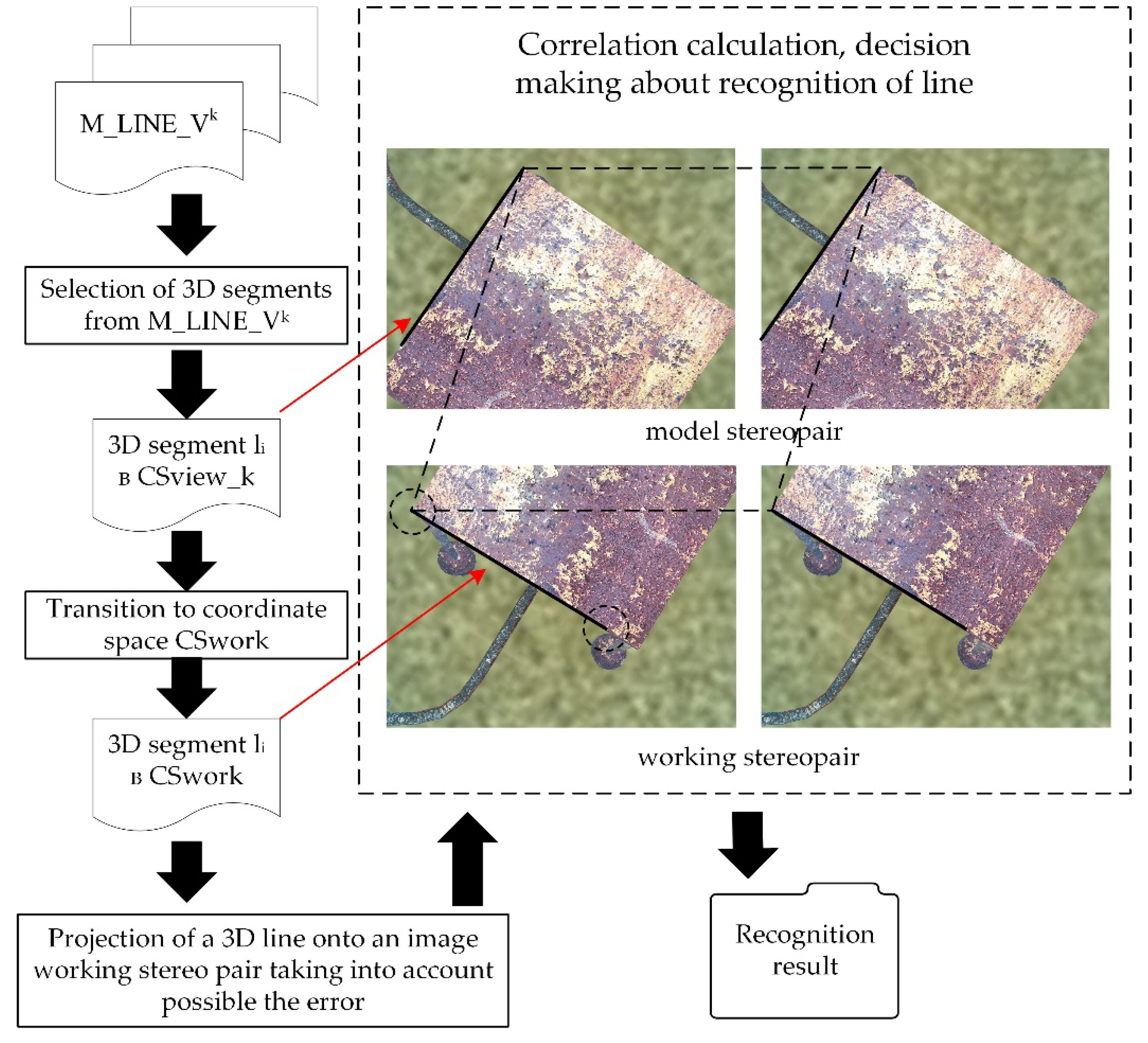
The first problem is solved by the below-described algorithm for matching segments, which uses: (a) the coordinate transformation matrix HCSwork, CSview_k, calculated from the points at the first stage, linking CSwork and CSview_k; (b) a set of 3D segments M_3D_LINE_VkVk_CSview_k (the kth view model). Each segment is defined by two spatial end points (in CSview_k), and for each end point there are pointers at its 2D images in the stereo-pair of frames. The advantage of this technique for defining a segment is that, as mentioned above, no image vectorization is required to match the segment line image in the model with the segment line image selected in the working stereo-pair of frames. In other words, the 3D problem of segment line matching is reduced to the 2D problem of matching the segment end points with calculation of correlation estimates (Figure 5). It should be taken into account that the segment line is an edge of the object’s face. Thus, when calculating the correlation of the images of the end points compared between the images, one use the rectangular arrays of pixels on the side from the segment line where the object is located (this information is saved while forming the model). Eventually, the proposed matching technique without using the vectorized form of images substantially reduces computational costs.
Algorithm for recognizing and calculating 3D coordinates of “line” type CEs. Segment lines are sequentially selected from the 3D set M_3D_LINE_VkVk_CSview_k; for each segment line, its 2D image is recognized in the stereo-pair of frames (im_L_object_work, im_R_object_work) of the analyzed position of the working (inspection) trajectory. Thus, for each segment line li (defined by the end points p1i and p2i) (Figure 5):
Pointers at 2D images of its two points in the stereo-pair of frames of the model are extracted.
The segment line is placed in the coordinate space CSwork using a matrix (calculated in step 1) and is projected onto the stereo-pair of frames of the working trajectory. The expression “segment line is projected” means the projection of the segment’s end points.
The coefficient of correlation between the compared images of the point in the model’s stereo-pair and the working stereo-pair of frames is calculated for each end point. When comparing the end points of the segment lines, the orientation of the vehicle by the compass of both the model and the working trajectory is used to provide the same orientation of the surrounding terrain compared.
In case of incomplete matching of the images, an attempt is made to find a match within a small radius, assuming that the projection (step 2) was performed with some error (step 3).
A decision is made about match or no-match of the images.
Figure 6.
Recognition of rectilinear segments.
The second problem, 3D reconstruction of the matched 2D images of segment lines in the working stereo-pair of frames, is solved in a traditional way: by matching the end points in the stereo-pair of frames using epipolar constraints, then by the ray triangulation method with calculating the 3D coordinates of the segment line’s end points in CSwork.
The result of recognition of all segment lines is the set S_3D_LINE_W_CSwork_match matched to M_3D_LINE_Vk_CSview_k_match. This result is input in the Table of Recognition Results, and the set is entered in S_3D_ LINE_CSobject_n.
Recognition and calculation of 3D coordinates of “corner” type CEs. CEs of the “corner” type are selected from the obtained set of “lines”. The selection algorithm is quite simple, since a “corner” CE is constructed from two segment lines lying in the same plane in space. By indicating whether the segment line belongs to a specific “corner”, ambiguity is eliminated in case of similar geometries of corners.
The result of recognition of all corners (the number of corners in the set S_3D_CORNER_W_CSwork_match matched to M_3D_CORNER_Vk_CSview_k_match, with pointers at these sets) is stored in the Table of Recognition Results, and the set is entered in S_3D_ CORNER_CSobject_n.
Object identification. Upon identifying the inspection trajectory of all three types of CEs at this position, corresponding to the object model, the data of the Table of Recognition Results is analyzed, and an algorithmic decision is made about identification of the object.
Calculation of the refined coordinate transformation matrix HCSwork, CSobject_n is carried out by the standard technique with minimization of the total coordinate deviation when matching of all points used. In this case, the matrix is calculated using all points belonging to CEs in the sets S_3D_ POINT_CSobject_n, S_3D_LINE_CSobject_n, S_CORNER_CSobject_n, since these points have a coordinate representation both in CSwork and in CSobject_n. As a result, the matrix HCSwork, CSobject_n (4 × 4) is calculated that links the CS of the AUV’s camera and the object’s CS. Then the AUV’s coordinates at each position of the trajectory are recalculated from the CS of the AUV or its camera to the object’s CS using this matrix , where are the uniform AUV’s coordinates in the CS of the AUV’s camera at this trajectory position. It should be noted that the CS of each position of the AUV’s trajectory is linked to the CS of the initial trajectory position using the author’s method for visual navigation [24].
The calculation of the AUV’s movement in the object’s coordinate space is performed using the matrix HCSwork, CSobject_n for transformation from CSwork into CSobject_n. As shown above, it is calculated as follows:
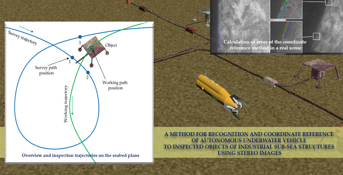
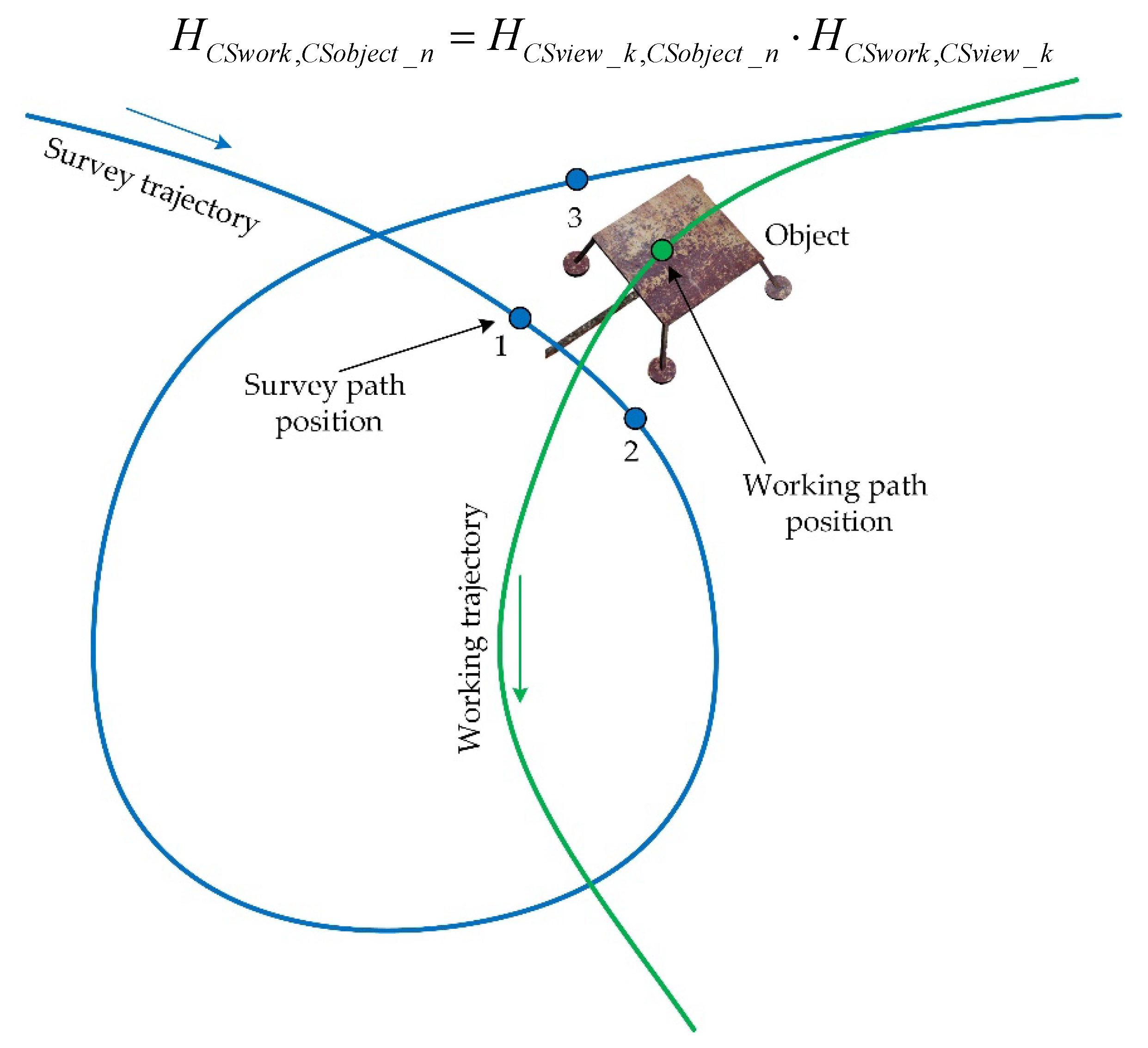
Figure 7.
Overview and inspection trajectories on the seabed plane. The views close to the object are indicated on the overview trajectory; for the position indicated on the inspection trajectory, the coordinate reference of the AUV to the object is calculated.
Figure 7.
Overview and inspection trajectories on the seabed plane. The views close to the object are indicated on the overview trajectory; for the position indicated on the inspection trajectory, the coordinate reference of the AUV to the object is calculated.
4. Experiments
We set up a series of experiments with a virtual scene and with actual data used in order to evaluate efficiency of the proposed method for coordinate referencing of AUV to SPS objects.
Model scene. To obtain a comparative estimate of accuracy of the coordinate referencing of the AUV to the object on the basis of one view and several views of the object, we conducted a series of experiments using a virtual scene generated by a modeling system [24]. The AUV’s altitude above the seabed varied from 6.4 to 7.1 m. The altitude above the well cover was 3.6 m; the frame rate, 10 fps; the resolution of images, 1200 × 900 pixels. The AUV’s coordinates were calculated at the trajectory positions every 10 frames of photography. The coordinate referencing was carried out by our method on the basis of the calculated matrix for coordinate transformation HCSwork,CSobject_n (see section 3). With the use of a single view of the overview trajectory (view 1, with 26 matched points), the accuracy of the AUV coordinate reference to the object was 32 mm. After points of views 2 and 3 were added and duplicates removed, the number of matched points grew to 76, and the accuracy, accordingly, increased to 2.8 mm. Additionally, we set up three more similar experiments, but with other three views in each (having smaller general fields of visibility of the object by the AUV’s camera at the considered position of the inspection trajectory). The resulting accuracies proved to be, as expected, slightly lower, 3.4, 4.2, and 12.3 mm, but still higher than those with the use of one view.
Thus, the use of several views of the overview trajectory to calculate the matrix HCSwork,CSobject_n in these experiments increased the accuracy of coordinate reference of the AUV to the object 3–11-fold. The reference accuracy was also confirmed by the high value of the calculated coefficient of correlation (up to 94%) of end points when segment lines were re-projected.
Actual data. The experiment was conducted in conditions close to an actual underwater mission: a submerged mockup of the object was installed on the seabed at a depth of 1.5 m; photographs were taken with a camera (Karmin2 (Nerian's 3D Stereo Camera, 25 cm)) housed in a sealed box and connected to a laptop aboard a boat. Photography (obtaining different views according to the above method) was carried out by an operator (diver).
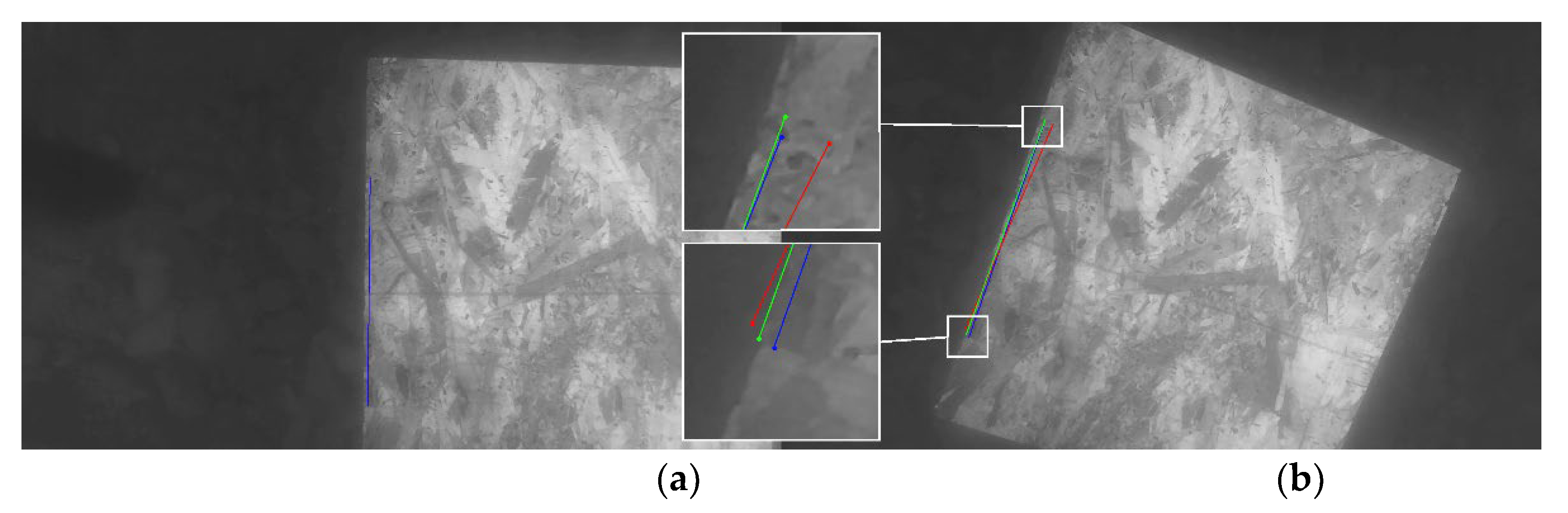
The technique for evaluating the accuracy of the proposed method in this experiment was based on indirect estimates (unlike the virtual scene, where, when calculating the error, the value set in the model was considered as a true value of the parameter being estimated). The accuracy error of the method was estimated in two ways: (a) the operator measured the distance between a pair of characteristic points on the object before submerging the object mockup to the seabed (the distance calculated by our method was then compared to this value, which provided the accuracy error of the method evaluated); (b) the operator explicitly indicated the images of the selected pair of object points in the views of the overview trajectory and in the view of the working trajectory, then the line calculated by our method between two 3D points of the object was projected onto the photograph of the working trajectory’s view, and then the error was calculated as the difference between the calculated projection of the line in the photograph and the line built by the operator (in pixels) (Figure 8). With the use of a single view (with 246 matched points), the accuracy error in 3D space (according to the first technique) averaged at 1.7% of the segment line’s length, and the average error of the re-projection of the end points of the segment lines in the photograph (according to the second technique) was 28px. With the use of three views (the number of matched points increased to 473), the error of the method (according to the first technique) decreased to 1.3%, and the re-projection error decreased to 13px. Thus, we confirmed the conclusion drawn in the case of the virtual scene about the increase in the accuracy of coordinate referencing of the AUV to an underwater object by using several views of overview trajectory.
5. Discussion
In this work, in the context of solving the problem of inspection of industrial sub-sea structures, a method for recognition and high-precision coordinate reference of AUVs to SPS objects is proposed and implemented. Accurate coordinate reference should provide the ability to plan the AUV inspection trajectory in the coordinate space of the SPS object to perform Maintenance and Repair operations in real time. The distinctive features of the method that realize its effectiveness are the following:
- a model of an underwater object is formed on the basis of views (foreshortening) of a previously completed survey trajectory using an automated technique with the participation of an operator. The technique does not require much labor, since it excludes preliminary direct in situ measurements and the use of documentation;
- the use of several views of survey trajectory contributes to a higher degree of object recognition at the inspection stage and, as experiments on synthetic and real data have shown, severalfold increases the accuracy of the coordinate reference of the APR to the object;
- the use of several types of geometric elements when comparing data obtained at the position of the inspection trajectory with the object model increases the reliability of object recognition, despite the noisiness of the images, and also increases the accuracy of the coordinate reference due to the use of an expanded set of points when calculating the coordinate transformation matrix;
- original and computationally low-cost algorithms for recognition and matching with the model of the characteristic geometric elements used (point features, segments and angles) have been developed.
Comparison with other methods. An example of an approach to solving the problem of inspection of underwater structures, based on the integrated use of sensors of various types, with an emphasis on processing sonar images, is the work described in [6]. For obstacle and inspection target detection, a scanning sonar is used. A pan–tilt enabled sensor head with camera, laser measurement and Multi Beam Echo Sounder is used to inspect the detected objects. Here, the problem of AUV movement relative to inspected objects is solved in a different way and without the use of optical images. Namely, the sonar images are automatically processed with edge detection and line extraction algorithms to get a simplified environment description, which is used by the guidance methods. The inspection sensors also provide the vehicle guidance system (VGS) with distance values to the inspection object. A laser gyroscope is used for navigation and positioning supported by a Doppler velocity log, a pressure sensor. Additionally, a scanning sonar provides data for collision avoidance. This sonar is mainly used for the reactive vehicle control by the VGS and for detection of the inspection objects.
In terms of comparison with our approach, the work [20], where the problem of recognizing underwater objects is solved, is also of interest. The method proposed by the authors is aimed at recognizing objects of a specific type (pipes and connecting elements), using an a priori accessible database of partial views of objects stored in the form of 3D point clouds. The methods are tested using an experimental dataset containing laser scans and AUV navigation data.
The difference between our approach and the above analogues is that: a) in our approach, the main emphasis is on solving the problem of coordinate reference of an AUV to an object using optical images, not limited only to the problem of object recognition; b) recognition is based on simple geometric elements characteristic of man-made objects (points, segments, angles), while providing some universality in relation to types of objects, and without requiring significant computational costs.
Future work. It is planned: a) extended experiments with the proposed method as part of the on-board AUV software to analyze the effectiveness of its use in different underwater conditions; b) comparison of the effectiveness of the algorithmic approach (using our method as an example) to solving the problem of identifying underwater objects, and the approach based on the use of neural networks.
6. Conclusions
This article presents a new approach to accurate coordinate referencing of AUV to SPS objects, based solely on stereo-image processing. It differs from other similar approaches by the use of a pre-made overview trajectory of the AUV to form models of SPS objects, by the use of different types of geometric elements that increase the degree of object recognition, and also by the use of original algorithms for matching the obtained visual data with an a priori model of the object.
Author Contributions
Conceptualization, V.B.; methodology, V.B., A.K.; software, A.K.; validation, V.B., A.K.; formal analysis, V.B.; investigation, V.B., A.K.; resources, V.B.; data curation, A.K.; writing—original draft preparation, V.B.; writing—review and editing, V.B., A.K.; visualization, A.K.; supervision, V.B.; project administration, V.B.; funding acquisition, V.B. All authors have read and agreed to the published version of the manuscript.
Funding
The study was funded by the Russian Science Foundation, grant No. 22-11-00032 (https://rscf.ru/project/22-11-00032/), and within the framework of the State budget topic No. 0202-2021-0004 of the Institute of Automation and Control Process, Far Eastern Branch, Russian Academy of Sciences (IACP FЕB RAS). The method for tracking a subsea pipeline (SP) using stereo-images taken by an autonomous underwater vehicle (AUV) was designed under the RSF grant No. 22-11-00032. The estimates of comparative efficiency of the methods for tracking a SP using stereo-images taken by an AUV were obtained under the State budget topic No. 0202-2021-0004 of the IACP FЕB RAS.
Conflicts of Interest
The authors declare no conflicts of interest.
References
- Mai, Ch.; Hansen, L.; Jepsen, K.; Yang, Zh. Subsea Infrastructure Inspection: A Review Study. In Proceedings of 6th International Conference on Underwater System Technology: Theory and Applications, 2016. [CrossRef]
- Zhang, Y.; Zheng, M.; An, Ch.; Seo, J. K. A review of the integrity management of subsea production systems: inspection and monitoring methods. Ships and Offshore Structures, 2019, vol. 14, Issue 8, pp. 1-15. [CrossRef]
- Manley, J.E.; Halpin, S.; Radford, N.; Ondler, M. Aquanaut: A New Tool for Subsea Inspection and Intervention. In Proceedings of OCEANS 2018 MTS/IEEE Conference, 22-25 Oct. 2018, Charleston, SC, USA. [CrossRef]
- Albiez, J.; Cesar, D.; Gaudig, C.; Arnold, S.; Cerqueira, R.; Trocoli, T.; Mimoso, G.; Saback, R.; Neves, G. Repeated close-distance visual inspections with an AUV. In Proceedings of the OCEANS 2016 MTS/IEEE Monterey, San Diego, CA, USA, 19 September 2016; pp. 1–8. [CrossRef]
- Terracciano, D.; Bazzarello, L.; Caiti, A.; Costanzi, R.; Manzari, V. Marine Robots for Underwater Surveillance. Curr. Robot. Rep.2020, 1, 159–167. [CrossRef]
- Jacobi, M. Autonomous inspection of underwater structures. Robot. Auton. Syst. 2015, 67, 80–86. [CrossRef]
- Bao, J., Li, D., Qiao, X., Rauschenbach, T. Integrated navigation for autonomous underwater vehicles in aquaculture: A review. Information Processing in Agriculture. Volume 7. Issue 1. 2020. P. 139-151. [CrossRef]
- Sahoo, A.; Dwivedy, S. K.; Robi, P.S. Advancements in the field of autonomous underwater vehicle. Ocean Engineering, Volume 181. 2019. pp. 145-160. https://. [CrossRef]
- Wirth, S.; Carrasco, P.L.N.; Oliver-Codina, G. Visual odometry for autonomous underwater vehicles. In Proceedings of the 2013 MTS/IEEE OCEANS. Bergen, Norway. 10–13 June 2013. pp. 1–6. https://. [CrossRef]
- Jung, J.; Li, J.-H.; Choi, H.-T.; Myung, H. Localization of AUVs using visual information of underwater structures and artificial landmarks. Intell. Serv. Robot. 2016. 10. pp. 67–76. [CrossRef]
- Gao, J.; Wu, P.; Yang, B.; Xia, F. Adaptive neural network control for visual servoing of underwater vehicles with pose estimation. J. Mar. Sci. Technol. 2016, 22, 470–478. [CrossRef]
- Xu, H.; Oliveira, P.; Soares, C.G. L1 adaptive backstepping control for path-following of underactuated marine surface ships. Eur. J. Control. 2020, 58, 357–372. [CrossRef]
- Fan, S.; Liu, C.; Li, B.; Xu, Y.; Xu, W. AUV docking based on USBL navigation and vision guidance. J. Mar. Sci. Technol. 2018, 24, 673–685. [CrossRef]
- Ferrera, M.; Moras, J.; Trouvé-Peloux, P.; Creuze, V. Real-Time Monocular Visual Odometry for Turbid and Dynamic Underwater Environments. Sensors. 2019, 19, 687. [CrossRef]
- Himri, K.; Ridao, P.; Gracias, N. 3D Object Recognition Based on Point Clouds in Underwater Environment with Global Descriptors: A Survey. Sensors. 2019, 19, 4451. [CrossRef]
- Kasaei, S.H.; Lopes, L.S.; Tomé, A.M.; Oliveira, M. An orthographic descriptor for 3D object learning and recognition. In Proceedings of the IEEE/RSJ International Conference on Intelligent Robots and Systems (IROS). Daejeon, Korea. 9–14 October 2016. pp. 4158–4163.
- Osada, R.; Funkhouser, T.; Chazelle, B.; Dobkin, D. Matching 3D models with shape distributions. In Proceedings of the SMI 2001 International Conference On Shape Modeling and Applications. Genova, Italy, 7–11 May 2001. pp. 154–166.
- Marton, Z.C.; Pangercic, D.; Rusu, R.B.; Holzbach, A.; Beetz, M. Hierarchical object geometric categorization and appearance classification for mobile manipulation. In Proceedings of the 10th IEEE-RAS International Conference on Humanoid Robots (Humanoids), Nashville, TN, USA, 6–8 December 2010; pp. 365–370.
- Rusu, R.B.; Blodow, N.; Beetz, M. Fast point feature histograms (FPFH) for 3D registration. In Proceedings of the IEEE International Conference on Robotics and Automation, ICRA’09, Kobe, Japan, 12–17 May 2009; pp. 3212–3217.
- Himri, K.; Ridao, P.; Gracias, N. Underwater Object Recognition Using Point-Features, Bayesian Estimation and Semantic Information. Sensors. 2021, 21, 1807. https://. [CrossRef]
- Chemisky, B.; Menna, F.; Nocerino, E.; Drap, P. Underwater Survey for Oil and Gas Industry: A Review of Close Range Optical Methods. Remote Sensing, 2021, 13 (14), pp.2789. https://. [CrossRef]
- Bobkov, V.; Kudryashov, A.; Inzartsev, A. Method for the Coordination of Referencing of Autonomous Underwater Vehicles to Man-Made Objects Using Stereo Images. J. Mar. Sci. Eng. 2021, 9, 1038. https://. [CrossRef]
- Rumson, A. G. The application of fully unmanned robotic systems for inspection of subsea pipelines. Ocean Engineering, 235. 2021: 109214. https://. [CrossRef]
- Bobkov, V. A.; Kudryashov, A. P.; Inzartsev, A. V. Technology of AUV High-Precision Referencing to Inspected Object. Gyroscopy and Navigation. 2019. Vol 10. №4. P. 322-329. https://. [CrossRef]
- Melman, S.; Bobkov, V.; Inzartsev, A.; Pavin, A. Distributed Simulation Framework for Investigation of Autonomous Underwater Vehicles' Real-Time Behavior. In Proceedings of the OCEANS'15 MTS/IEEE Washington DC. October 19-22. 2015.
Figure 2.
Building the coordinate system (CS) (X'Y'Z') linked with the object using the segment line: segment [P1, P2] is set in the camera’s CS; point P1 is the origin of the CS being built; the direction of the Z'-axis coincides with the direction of the Z-axis of the external CS; [P1, P2'] is the projection of the segment [P1, P2] onto the plane perpendicular to the Z'-axis; the X'-axis is determined by the direction [P1, P2']; the Y'-axis is completed by the right CS rule.

Figure 3.
Recognition of an SPS object on the basis of stereo frames using several object’s views of the overview trajectory (three views are shown).
Figure 3.
Recognition of an SPS object on the basis of stereo frames using several object’s views of the overview trajectory (three views are shown).
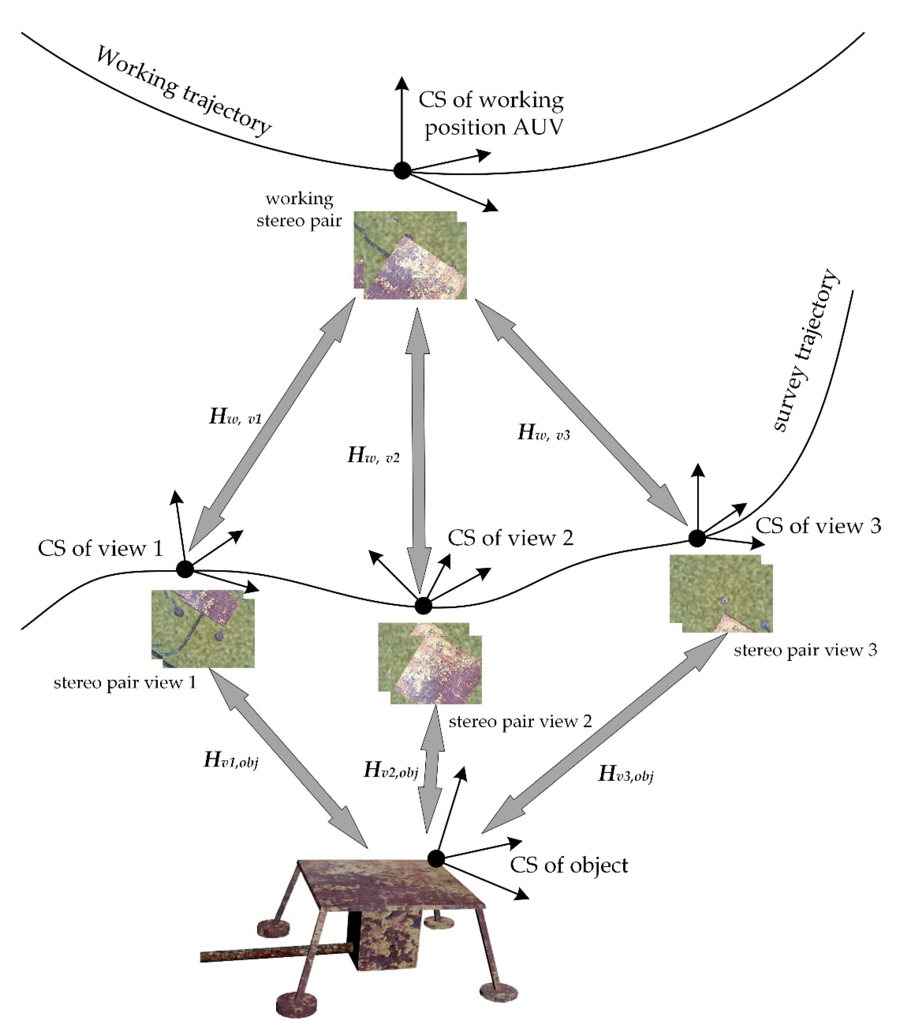
Figure 4.
Object recognition on the basis of point features by comparing the left frames of the model and working stereo-pairs.
Figure 4.
Object recognition on the basis of point features by comparing the left frames of the model and working stereo-pairs.
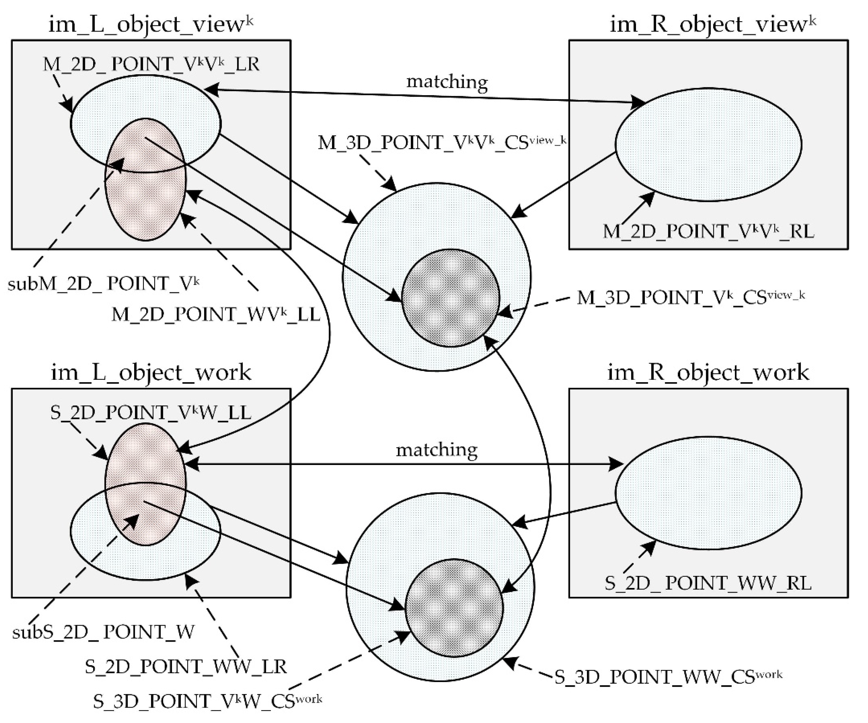
Figure 5.
Matching a segment line of the object model with its image in the photograph of the working trajectory.
Figure 5.
Matching a segment line of the object model with its image in the photograph of the working trajectory.
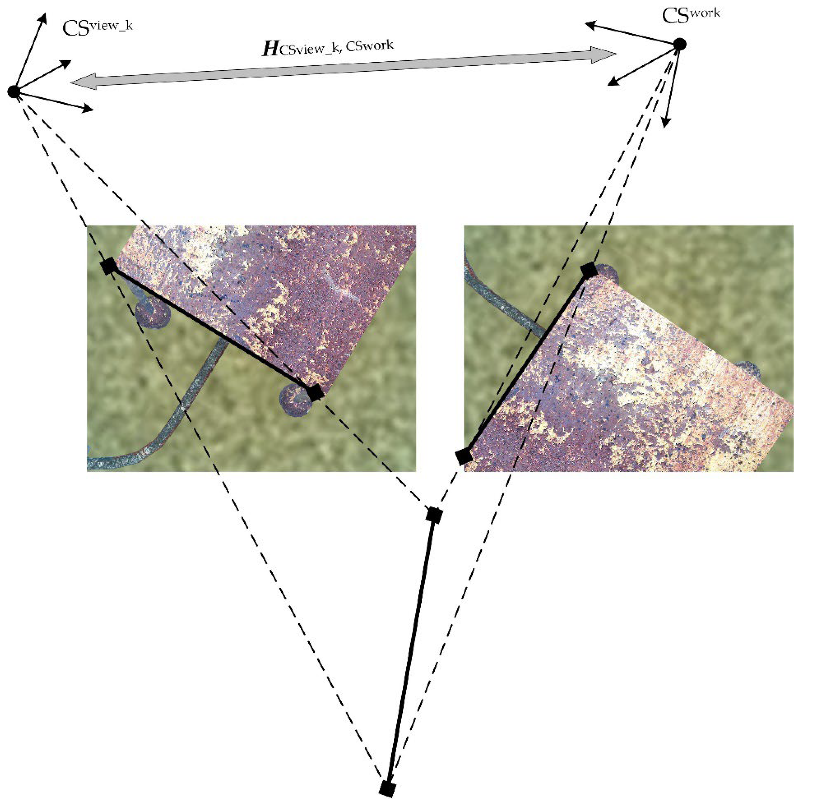
Figure 8.
Calculation of error of the coordinate reference method in a scene with a mockup of a subsea production system (SPS) object: (a) the left figure is a photograph of the object for a view on the overview trajectory, where the blue line was built by the operator; (b) the right figure is a photograph of the object for a view on the working trajectory. The blue line built by the operator is considered as a true value to which the result of the method is compared (a projection onto the photograph of the spatial line calculated by the method). The red line is a projection of the line calculated on the basis of a single view; the green line is a projection of the line calculated on the basis of three views.
Disclaimer/Publisher’s Note: The statements, opinions and data contained in all publications are solely those of the individual author(s) and contributor(s) and not of MDPI and/or the editor(s). MDPI and/or the editor(s) disclaim responsibility for any injury to people or property resulting from any ideas, methods, instructions or products referred to in the content. |
© 2024 by the authors. Licensee MDPI, Basel, Switzerland. This article is an open access article distributed under the terms and conditions of the Creative Commons Attribution (CC BY) license (http://creativecommons.org/licenses/by/4.0/).
Copyright: This open access article is published under a Creative Commons CC BY 4.0 license, which permit the free download, distribution, and reuse, provided that the author and preprint are cited in any reuse.


