
Submitted:
25 July 2024
Posted:
29 July 2024
You are already at the latest version
Abstract
Tungsten balls with sub-100-μm diameter can function as probe tips for micro-coordinate measuring machines (CMMs) to measure ultraprecise workpieces such as ceramic bearings with a high aspect ratio. A high-precision measuring system was proposed to evaluate the roundness error of the self-made tungsten ball tips. The principles and mathematical models of the measuring system are illustrated, and the fabrication principle of tungsten balls is introduced. An analysis was conducted on the maximum allowable contact force and bending strength of the tungsten ball tips, and the elastic mechanism was designed based on the analysis. A ruby probe with a sphericity error of 130 nm (A-5003-0577, Renishaw Corporation) used as a reference sphere was measured to verify the system's effectiveness. Repeated measurement experiments were performed for two tungsten ball tips. The results show the roundness error of the tungsten ball-A is between 568.3 and 586.2 nm with a standard deviation of 6.6 nm while the tungsten ball-B’s roundness error is between 898.5 and 958.0 nm with a standard deviation of 19.7 nm. The uncertainty is calculated as 125.8 nm. The developed system can stably measure the roundness of the tungsten ball tips.
Keywords:
tungsten ball tips
; roundness measurement and evaluation
; uncertainty evaluation
1. Introduction
CMMs are a common method in the field of precision measurement, and the quality of the probe tips significantly impacts the performance of the CMM [1]. The probe tips currently used are mostly ruby balls produced by Renishaw, made from 99% alumina crystals cut and progressively machined to be high-precision spheres with extremely smooth surfaces, high compressive strength, and high mechanical wear resistance. However, they are unsuitable for measuring workpieces made of certain materials due to their material properties, such as adhesive wear with aluminum and frictional wear with cast iron [2]. There are also probe tips made of other materials, such as glass fiber spheres and silicon nitride spheres. However, none are widely feasible due to their size and hardness [3,4]. Because of high hardness and wear resistance, the tungsten wire was used to fabricate probe tips with a diameter of less than 100 μm to measure the ultraprecision workpiece [5,6,7]. The roundness error of the tungsten ball tips must be evaluated accurately to reduce the influence on the measurement accuracy of the micro-CMMs.
Many instruments have been developed for roundness measurements, such as Mitutoyo Roundtest RA-2200, ZEISS Rondcom NEX, and Mahr Federal MMQ 200 Formtester, which are highly accurate and stable but too expensive. Many researchers also presented different strategies for measuring roundness. Zhao et al. developed a roundness measuring system composed of a reconstructed atomic force microscope (AFM), precision rotating air-bearing, and assistant transform shaft [8]. The system was used to measure a hollow plastic ball with a diameter of 460 μm. Results showed that the maximum roundness error is 389.5 nm. However, the performance was not further researched using smaller-sized balls. Manske et al. used AFM to scan the ruby sphere with a diameter of 300 μm to obtain surface information and used the stitching algorithm to integrate multiple AFM scan datasets, obtaining the diameter and roundness error of the ruby ball with a standard deviation of 3.7 nm. They also analyzed how the shape of the reference surface and the AFM tips affect the measurement of radius and roundness, improving the reliability of the approach proposed [9,10,11].
Fang et al. presented a high-resolution scanning probe comprising a large aspect ratio tungsten probe and a quartz tuning fork [12,13]. They placed the two probes symmetrically to measure the maximum cross-sectional circular profile of microspheres and separated the main errors during measurement using the inversion method. This approach demonstrates excellent sensitivity and repeatability but is constrained by a limited number of measurement points, significantly impacting result reliability. Moreover, spherical probes cannot guarantee that the measured data is always the diameter due to misalignment. Cai et al. used plane mirrors as probes to contact the microsphere to solve this problem [14]. The system with a precision rotating stage and two high-precision displacement sensors can separate the rotating spindle’s run-out error and the tested sphere’s eccentricity error. However, it fails to measure microspheres with a diameter of tens of microns due to the limited resolution and accuracy of the sensors.
Ito et al. proposed a method for measuring the form error of probe tips of CMMs by using a reference sphere and the CMM itself [15]. Federal Institute of Metrology (METAS) proposed a three-sphere mutual measurement method based on ultraprecision CMM [16]. This method has high accuracy but requires ultra-precise CMM, which is considerably expensive.
Non-contact methods are also widely studied because of their advantages. Song et al. and Chen et al. reconstructed microspheres for 3D reconstruction using multiple 2D images of microspheres obtained by optical means [17,18]. This method can achieve a three-dimensional evaluation of microsphere morphology, but its accuracy is compromised due to optical imaging errors.
Interferometers are also used to measure microsphere roundness. National Institute of Standards and Technology (NIST) used a spherical Fizeau interferometer to measure a precision silicon sphere with a nominal radius of 46.8 mm [19]. Physikalisch-Technische Bundesanstalt (PTB) reconstructed the absolute shape of spheres using the sphere interferometer of PTB in combination with a stitching approach [20,21]. The tested sphere is fixed on the rotating spindle, and two interferometers are placed on both sides of the microsphere, scanning the microsphere’s surface, which is used to reconstruct the sphere’s shape using the stitching algorithm. The method could reconstruct absolute radii accurately in the nanometer range, but it is only suitable for spheres with high reflectivity. Mitutoyo developed a measuring system consisting of a Fizeau interferometer and a five-axis platform to measure microsphere roundness. This system is particularly suitable for those spheres with rods, such as CMM probe tips [22]. The system has a high accuracy but is limited by reference mirrors and calibrators and fails to measure spheres with a diameter of tens of microns.
The authors’ group has also researched roundness measurement methods, developing a system specifically for microspheres based on the two-point method [23]. This system used two homemade Michelson interferometers (MIs) placed symmetrically to measure the variation of the microsphere’s diameter. Considering the strategy for evaluating roundness according to diameters is factually inaccurate. The authors’ group presented a novel roundness measurement method based on radii for microspheres and an optimized measurement system [24]. Meanwhile, an analog electronic method was developed to eliminate nonlinear errors of sinusoidal waves in interferometry [25], improving interferometer performance. However, the measuring system fails to measure tungsten balls because the contact force tungsten balls can withstand is considerably limited due to the size and material.
In this study, principles and calculation models are introduced, and the measuring system’s elastic mechanism was designed according to the force analysis of the tungsten ball tips. Moreover, comparative experiments verified the system’s correctness and effectiveness.
2. Measuring System and Principles
As Figure 1 shows, the roundness measuring system mainly consists of a high-precision rotating stage, two MIs, and two elastic mechanisms and adjustment mechanisms. Both ends of the elastic mechanism are plane mirrors; one is used as a probe to contact the tested sphere, and the other is a measuring mirror of MI that functions as a displacement sensor. During the measurement, the tested sphere is fixed on the center of the rotating stage, rotating with the stage, and the probes are firmly attached to the tested microsphere to ensure that the elastic mechanism can convert the variation of the radius into displacement and transmit it to the measuring mirrors, which will be measured by the MIs. The tested microsphere is extremely small, with a diameter of just a few tens of microns and fluctuations in radius ranging from a few nanometers to several micrometers. So, the high-resolution Michelson interferometers are selected as displacement sensors to capture subtle changes accurately. The XYZ stages are used to adjust the position of the elastic mechanism, ensuring that the center of the contact mirror aligns with the sphere’s center.
The specific measurement process is illustrated in Figure 2. Before the measurement, the two probes are aligned without the tested sphere, and the readings of the MIs are set to zero. When the measurement begins, the tested sphere is placed between the probes, and the initial readings of the MIs are recorded respectively as Ra(0) and Rb(0). As the tested sphere rotates to an angle θ, the sensor outputs are denoted as Ra(θ) and Rb(θ). It should be noted that the center of the tested sphere moves to point O’ from point O during rotation, introducing an eccentric error denoted as E(θ).
Then, r(θ) that the true radius of the tested microsphere at any angular can be calculated using the mathematical model depicted in Figure 3 [24]. Here, Δr(θ) is the variation of microsphere radius as it rotates to an angle θ; N is the number of sampling points in a cycle. Eccentric error E(θ) is π-symmetrical, which can be determined by optimization techniques.
After obtaining all the true radius r(θ), the roundness of the test sphere’s equatorial circle can be evaluated using the minimum zone circle method (MZC).
The coordinates corresponding to each r(θ) are determined by Equation (1), fitted to a circle in the right-angle coordinate system.
The circle’s centers to be verified are selected by Equations (2) and (3).
where n is the iteration number; xi(n) and yj(n) are the horizontal and vertical coordinates of the circle’s center to be verified within the search area; xo(n) and yo(n) are the center coordinates of the search area during the n-th iteration, initially, xo(0) and yo(0) are both set to zero.
The distance from each (xi(n), yj(n)) to every point on the circumference is calculated by Equation (4), and the roundness error corresponding to each (xi(n), yj(n)) can be determined by Equation (5).
The (xi(n), yj(n)) corresponding to the minimum value of er(n) is used as the center of the search area for the next iteration. The center of the circle to be verified for the next iteration is determined through Equations (2) and (3) and subsequently input into Equations (4) and (5) to compute the new er(n).
The iteration stops when the new value of er(n) agrees with the previous iteration’s value. Then the (xi(n), yj(n)) corresponding to er(n) is regarded as the true center of the circle while the er(n) is the true roundness error. The er(n) value comparison is set to start after 10 iterations to avoid accidental errors. The specific process is shown in Figure 4.
3. Analysis and Design of Elastic Mechanism
3.1. Force Analysis of Tungsten Ball Tips
The authors’ group proposed a method for fabricating micro tungsten ball tips via arc discharge to measure complex micro components [6]. This method was implemented in an argon environment. Tungsten wire and spark plug were used as the cathode and the anode respectively, and an electric arc was generated by applying high enough voltage to electrodes, causing the atoms at the discharge point to evaporate and emit charged particles in a plasma state. The collision between accelerated electrons and neutral molecules led to a sharp increase in argon temperature, melting the tungsten wire. The molten tungsten condensed into tungsten balls due to the liquid surface tension. Figure 5 is a tungsten ball under a scanning electron microscope (SEM). The form of the tungsten balls will be influenced by electrode spacing, pulse voltage, pulse frequency, discharge duration, etc.
The raw material used to fabricate tungsten balls is a tungsten wire with a diameter of 100 μm, and the diameter of the tungsten balls usually ranges from tens to over 100 μm. Typically, the diameter of the tungsten rod near the ball is less than 100 μm due to melting. Therefore, the force that the tungsten ball can withstand during the contact measurement is relatively small, it is essential to analyze the force on it and design a suitable elastic mechanism accordingly.
The analysis considers two primary forces: the maximum permissible contact force denoted as Fm which the tungsten ball can withstand without damage, and the maximum bending stress denoted as Fb which the rod can withstand without bending. Figure 6 shows the force on a tungsten ball. The tungsten ball is secured on the fixing stage during measurement, with the distance from the ball’s center to the top of the fixture being L. The rod has a diameter of 100 μm, while the diameter of the tungsten ball is D, typically less than 100 μm. F1 and F2 represent preloaded forces exerted by elastic mechanisms on the tungsten ball tip. If (|F1|+| F2|)>Fm, it will lead to the deformation or even damage of the tungsten ball, while if | F1- F2|>Fb, the rod will bend or break, so the value of F1 and F2 must be constrained by Fm and Fb.
The maximum permissible contact force can be calculated by the Hertzian formula.
where E1 and υ1 are Young’s modulus and Poisson coefficients of the tungsten ball, which are respectively 345GPa and 0.28; E2 and υ2 are Young’s modulus and Poisson coefficients of the contact mirror made of silicon oxide, which is 73.1 GPa and 0.16. σy is the yield limit of the contact mirror, and D is the diameter of the tested tungsten ball, calculated as 100 μm, and Fm should be less than 6.88 mN considering the sharpening of the rod near the tungsten ball.
The maximum bending stress of the rod can be calculated by the following equation:
Where Mmax is the maximum bending moment, L is the distance from the center of the ball to the top of the fixing stage, Wz is the flexural section coefficient, [σ] is the allowable stress limit, and d is the diameter of the rod. The value of Fb is calculated to be 39.3 mN.
Taking the above into consideration, F1 should ideally be equal to F2 and should not exceed 3 mN.
3.2. Design of Elastic Mechanism
The elastic mechanism functions to convert the radius variation of the tungsten ball into displacement and transmit it to the measuring mirror which will be sensed by the interferometer. This requires that the elastic mechanism is sufficiently sensitive to ensure that the probe responds promptly to the fluctuation of the radius. While the preload force has already been restricted, minimizing friction in the elastic mechanism is crucial, for which the elastic mechanism shown in Figure 7 was designed.
A precision ball slide with a frictional coefficient of 0.004 and a basic dynamic load rating of 1400N (BWU 30-30, IKO Corporation) is used as the core component of the elastic mechanism to provide movement. A plane mirror with a surface roughness of 2 nm functions as a probe to contact the microspheres to ensure that the measured value between the two probes is consistently the diameter of the microsphere as it rotates. The plane mirror probe and measuring mirror of MI are linked to the slide via rods and connection mechanisms to maintain perfect synchronized movement. The centers of the two plane mirrors are designed to be coaxial to avoid the effect of Abbe error.
The entire mechanism is mounted onto the XYZ stage by a fixing stage to adjust the position, aligning with the microsphere. The XYZ stage drives the elastic mechanism toward the microsphere, applying preload force provided by the compressing spring. Considering the small contact force the tungsten ball can handle, a spring with low stiffness is chosen to improve the sensitivity of the elastic mechanism. The stiffness can be determined by Equation (8).
According to the above equation, a SUS 304 spring with a shear modulus (G) of 70 GPa, a wire diameter (d) of 0.2 mm, a center diameter (D) of 7 mm, and an effective number of turns (n) of 30 is selected, which the stiffness is calculated as 1.32 mN/mm. The springs are compressed by 2 mm on both sides to ensure force equilibrium for the tungsten ball, generating a preload force of 2.64 mN. Figure 8 shows the elastic mechanism in a state where preload force has been applied.
4. Experiments and Results
A series of experiments were conducted to validate the performance of the proposed measuring system.
4.1. Experiment Setup
The physical measuring system is shown in Figure 9. The tested microsphere was positioned above the rotating stage and adjusted to align with the center of the spindle through the XY stage and angle stage below. The displacement sensors on both sides are self-developed MIs with a resolution of 5 nm, which can sensitively detect tiny fluctuations in the radius of the microsphere. A high-precision air floating rotating stage with an angular rotation error of 0.1’’ and a radial rotation error of 70 nm was used to provide rotation. In experiments, the MIs sampled data at a frequency of 100 Hz, while the rotating stage maintained continuous movement at a speed of 5 r/min, which means that 1200 sets of data were recorded per circle. Experiments were performed in the laboratory with a constant temperature of 20 ℃± 0.5℃.
4.2. Measuring Experiment of Standard Microsphere
As Figure 10 shows, a standard ruby probe with a diameter of 700 μm and a sphericity error of 130 nm (A-5003-0577, Renishaw Corporation) was measured to assess the feasibility of the developed system. The measurement experiment was conducted six times. Table 1 presents the maximum and minimum radii of the ruby probe obtained for each measurement and the corresponding roundness error.
The results show that the roundness errors of the tested sphere are between 115.5 and 130.1 nm with a standard deviation of 4.8 nm, and the maximum radius fluctuates within 10 nm, as does the minimum radius. Figure 11 shows the profiles of the equatorial circular section of the ruby sphere in the polar coordinate system consisting of 1200 sets of data. The polar angle represents the angle the tested microsphere rotated, and the polar radius is the sphere’s radius. The starting point of the polar radius is chosen accordingly instead of starting from zero to display the variation of the microsphere’s radius clearly.
Although the measured roundness errors slightly deviate from the standard value, the experimental results show good repeatability and stability, affirming the measuring system’s feasibility.
4.3. Measuring Experiment of Tungsten Ball Tips
The feasibility of the measuring system has been verified by measuring ruby microsphere. The measurement experiments for two different tungsten ball tips were performed. Figure 12 shows one of the tungsten ball tips mounted on the pedestal. The procedures and parameters are consistent with the above, and the measurement results of two tungsten ball tips are given in Table 2 and Figure 13.
The results show the maximum and minimum radii of the tungsten ball-A measured are respectively 49.2614 and 48.6682 μm, and the roundness errors are between 568.3 and 586.2 nm with a standard deviation of 6.6 nm. The tungsten ball-B’s maximum and minimum radii are 41.5672 and 40.6064 μm with roundness between 898.5 and 958.0 nm and a standard deviation of 19.7 nm. The circular profiles of two tungsten ball tips are shown in Figure 13.
From the above results, it is evident that the repeatability of measuring tungsten balls is slightly worse compared to the ruby microsphere. It is mainly because the ruby ball rod material is typically made up of stainless steel or tungsten carbide, which are both size and hardness far better than tungsten wire, offering better bending resistance to cope with the imbalance of the contact force on both sides due to the slider friction and the motion unevenness, etc.
For tungsten spheres, the repeatability of measurements worsens as the sphere’s diameter decreases. This is mainly due to the sharpening of the rod near the balls, reducing the bending resistance of the tungsten ball, which is more pronounced as the diameter of the tungsten ball decreases. Moreover, the rod is prone to deformation and even breaks during long-time measurements. Therefore, the duration of each measurement should be limited to less than two minutes to avoid these effects.
4.4. Uncertainty Evaluations
The sources of measurement uncertainty for the designed measuring system mainly include the two MIs, the rotating stage, and the plane mirror probe of elastic mechanisms. Research on the resolution, drift, and repeatability of the two MIs was detailed in [24]. The resolutions of MIs are both 3 nm, and the drifts are respectively 48 and 40 nm. The repeatability of the MIs over a 100-micron stroke are 9.7 and 5.4 nm. Assuming that the resolution and drift are uniform distributions, the combined standard uncertainties of the MIs can be calculated as follows.
The radial runout of the rotating stage is 70 nm, while the angular rotation error is 0.1′′. The radius of the rotary stage is 107.5 mm, and the radial runout due to the angular error is then calculated as 52 nm. These errors are uniform distribution. The uncertainty caused by the rotating stage can be calculated.
The surface roughness of the plane mirrors functioned as a probe is 2 nm. Assuming that it uniformly distributes, the uncertainty components caused by the mirror can be obtained as follows.
Finally, the combined standard uncertainty of the measuring measurement system can be calculated as follows.
Assuming a confidence probability of approximately 95% (k=2), the expanded uncertainty of the measuring system is approximately 125.8 nm.
5. Conclusions
A high-precision measuring system was designed to evaluate the roundness error of the self-developed tungsten ball tips and the effectiveness has been verified by measuring a standard ruby probe. Experiment results show the roundness of the tungsten ball tip-A range between 568.3 and 586.2 nm with a standard deviation of 6.6 nm while the tungsten ball-B is between 898.5 and 958.0 nm with a standard deviation of 19.7 nm which repeatability of measurements is influenced by the diameter of tungsten balls. The expanded uncertainty was also analyzed and calculated as 125.8 nm. The developed measuring system has the advantages of high precision, sensitivity, and repeatability, which can also be used to measure other microworkpieces with circular features by designing different fixing devices. Furthermore, it is promising to achieve the measurement and evaluation of sphericity by optimizing the design of contact probes and related mechanisms.
Author Contributions
Methodology, K.F.; software, C.Z. and W.Z.; validation, C.Z. and Y.L.; formal analysis, R.L. and W.Z.; resources, R.L. and Z.C.; data curation, C.Z.; writing—original draft preparation, C.Z..; writing—review and editing, R.L., Z.C. and K.F. All authors have read and agreed to the published version of the manuscript.
Funding
This research was funded by the Anhui Province Special Project on Standardization of Quality Infrastructure, grant number JZ2023AHST0692 and the National Natural Science Foundation of China, grant number 52075143.
Institutional Review Board Statement
Not applicable.
Informed Consent Statement
Not applicable.
Data Availability Statement
The original contributions presented in the study are included in the article, further inquiries can be directed to the corresponding author.
Conflicts of Interest
The authors declare no conflicts of interest.
References
- Fan, K.C.; Cheng, F.; Pan, W.T.; Li, R. Analysis of the contact probe mechanism for micro-coordinate measuring machines. Opt. Instrum. Data Process. 2010, 46, 340–346. [Google Scholar] [CrossRef]
- Yang, P.; Takamura, T.; Takahashi, S.; Takamasu, K.; Sato, O.; Osawa, S.; Takatsuji, T. Development of high-precision microcoordinate measuring machine: Multi-probe measurement system for measuring yaw and straightness motion error of XY linear stage. Precis. Eng. 2011, 35, 424–430. [Google Scholar] [CrossRef]
- Ito, S.; Shima, Y.; Kato, D.; Matsumoto, K.; Kamiya, K. Development of a microprobing system for side wall detection based on local surface interaction force detection. Int. J. Autom. Technol. 2020, 14, 91–98. [Google Scholar] [CrossRef]
- Claverley, J.D.; Leach, R.K. A vibrating micro-scale CMM probe for measuring high aspect ratio structures. Microsyst. Technol. 2010, 16, 1507–1512. [Google Scholar] [CrossRef]
- Li, R.; Chen, C.; Fan, K.; Wang, Z.; Liu, F.; Huang, Q. Fabrication and study of micro monolithic tungsten ball tips for micronano-CMM probes. Micromachines 2018, 9, 133. [Google Scholar] [CrossRef]
- Cheng, Z.Y.; Yao, P.; Wang, Y.J.; Chen, C.; Chen, L.J.; Li, R.J.; Huang, Q.X. High-precision fabrication of micro monolithic tungsten ball tips via arc discharge and the Taguchi method. Micromachines. 2021, 12, 1042. [Google Scholar] [CrossRef] [PubMed]
- He, Y.X.; Lin, R.W.; Li, J.; Li, R.J.; Yao, P.; Cheng, Z.Y.; Huang, Q.X.; Fan, K.C. Nanoprecision Measurement of High-Aspect-Ratio Microholes Using Sub-100 μm Tungsten Ball Tip. IEEE Sens. J. 2023, 23, 30893–30902. [Google Scholar] [CrossRef]
- Zhao, X.S.; Sun, T.; Yan, Y.D.; Li, Z.Q.; Dong, S. Measurement of roundness and sphericity of the microsphere based on atomic force microscope. Key Eng. Mater. 2006, 315, 796–799. [Google Scholar] [CrossRef]
- Oertel, E.; Manske, E. Radius and roundness measurement of microspheres based on a set of AFM surface scans. Meas. Sci. Technol. 2021, 32, 044005. [Google Scholar] [CrossRef]
- Dai, G.; Degenhardt, J.; Hu, X.; Wolff, H.; Tutsch, R.; Manske, E. A feasibility study towards traceable calibration of size and form of microspheres by stitching AFM images using ICP point-to-plane algorithm. Meas. Sci. Technol. 2023, 34, 055009. [Google Scholar] [CrossRef]
- Oertel, E.; Manske, E. Influence of the reference surface and AFM tip on the radius and roundness measurement of micro spheres. Meas. Sci. Technol. 2023, 35, 025010. [Google Scholar] [CrossRef]
- Fang, C.Z.; Huang, Q.X.; Xu, J.; Cheng, R.J.; Chen, L.J.; Li, R.J.; Wang, C.Q.; Zhang, L.S. A measurement method of microsphere with dual scanning probes. Appl. Sci. 2019, 9, 1598. [Google Scholar] [CrossRef]
- Fang, C.Z.; Huang, Q.X.; Ding, X.M.; Cheng, R.J.; Zhang, L.S.; Wang, C.Q.; Mei, J.; Li, H.L. Measurement and uncertainty evaluation of the microsphere used for micro-CMM probe. Meas. Sci. Technol. 2019, 31, 025004. [Google Scholar]
- Cai, Y.; Xie, B.; Ling, S.; Fan, K.C. On-line measurement method for diameter and roundness error of balls. Nanomanuf. Metrology. 2020, 3, 218–227. [Google Scholar] [CrossRef]
- Ito, S.; Tsutsumi, D.; Kamiya, K.; Matsumoto, K.; Kawasegi, N. Measurement of form error of a probe tip ball for coordinate measuring machine (CMM) using a rotating reference sphere. Precis. Eng. 2020, 61, 41–47. [Google Scholar] [CrossRef]
- Küng, A.; Meli, F.; Thalmann, R. Ultraprecision micro-CMM using a low force 3D touch probe. Meas. Sci. Technol. 2007, 18, 319. [Google Scholar] [CrossRef]
- Song, L.M.; Zhou, X.L.; Qu, X.H.; Xu, K.X.; Lv, L.N. Novel 3D sphericity evaluation based on SFS-NDT. NDT&E Int. 2005, 38, 442–447. [Google Scholar] [CrossRef]
- Chen, L.C. Automatic 3D surface reconstruction and sphericity measurement of micro spherical balls of miniaturized coordinate measuring probes. Meas. Sci. Technol. 2007, 18, 1748. [Google Scholar] [CrossRef]
- Griesmann, U.; Soons, J.; Wang, Q.; DeBra, D. Measuring form and radius of spheres with interferometry. CIRP Ann. 2004, 53, 451–454. [Google Scholar] [CrossRef]
- Bartl, G.; Krystek, M.; Nicolaus, A.; Giardini, W. Interferometric determination of the topographies of absolute sphere radii using the sphere interferometer of PTB. Meas. Sci. Technol. 2010, 21, 115101. [Google Scholar] [CrossRef]
- Bartl, G.; Krystek, M.; Nicolaus, A. PTB’s enhanced stitching approach for the high-accuracy interferometric form error characterization of spheres. Meas. Sci. Technol. 2014, 25, 064002. [Google Scholar] [CrossRef]
- Hagino, T.; Yokoyama, Y.; Kuriyama, Y.; Haitjema, H. Sphericity measurement using stitching interferometry. Key Eng Mater. 2012, 523, 883–888. [Google Scholar] [CrossRef]
- Fan, K.C.; Wang, N.; Wang, Z.W.; Zhang, H. Development of a roundness measuring system for microspheres. Meas. Sci. Technol. 2014, 25, 064009. [Google Scholar] [CrossRef]
- Zhao, W.K.; Li, R.J.; Duan, L.H.; Cheng, Z.Y.; Cheng, R.J.; Huang, Q.X.; Fan, K.C. New radius and roundness measurement for microspheres using a high-precision run-out error separation method. IEEE Trans. Instrum. Meas. 2022, 71, 1–10. [Google Scholar] [CrossRef]
- Zhao, W.K.; Li, R.J.; Li, X.; He, Y.X.; Cheng, Z.Y.; Zhang, L.S.; Pan, Q.S.; Huang, Q.X.; Fan, K.C. Analog electronic method for solving nonlinear errors of sinusoidal waves in interferometry. IEEE Trans. Instrum. Meas. 2021, 70, 1–10. [Google Scholar] [CrossRef]
Figure 1.
Schematic of the measurement equipment.
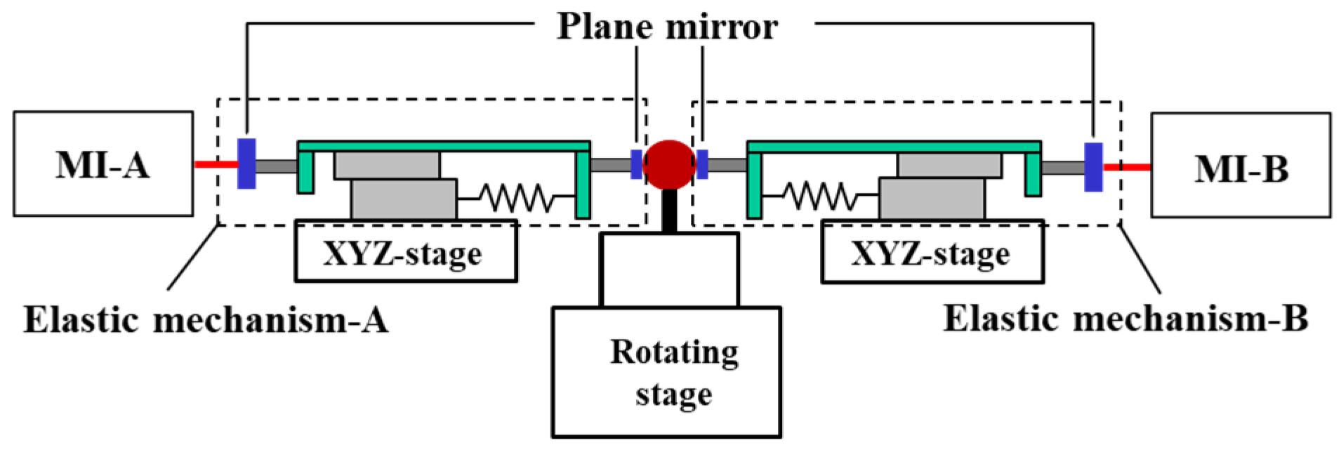
Figure 2.
Schematic of the measurement process (a)before the measurement, (b) at the beginning of the measurement, (c) during the measurement.
Figure 2.
Schematic of the measurement process (a)before the measurement, (b) at the beginning of the measurement, (c) during the measurement.
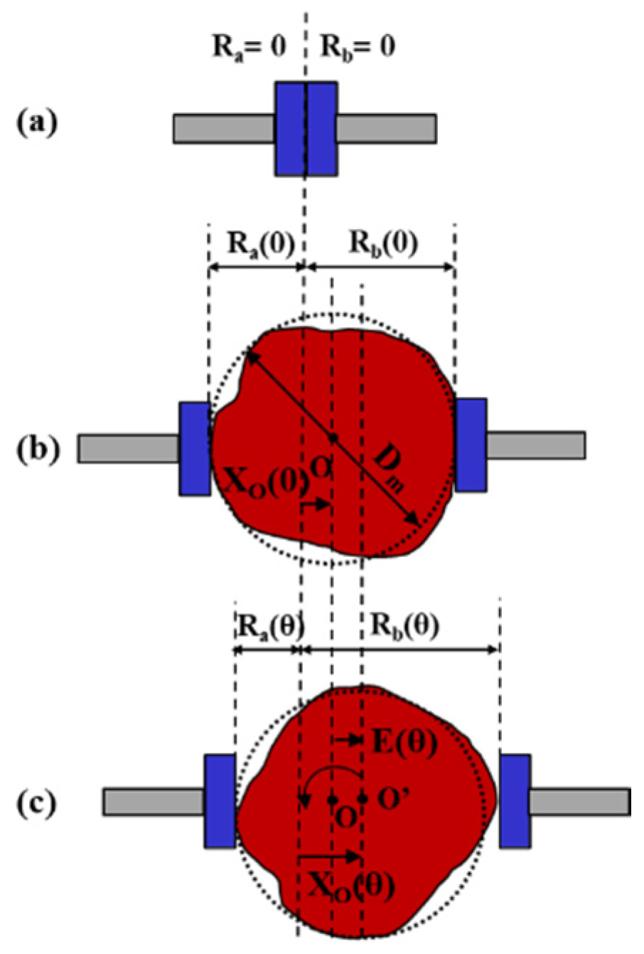
Figure 3.
Radius calculation model.
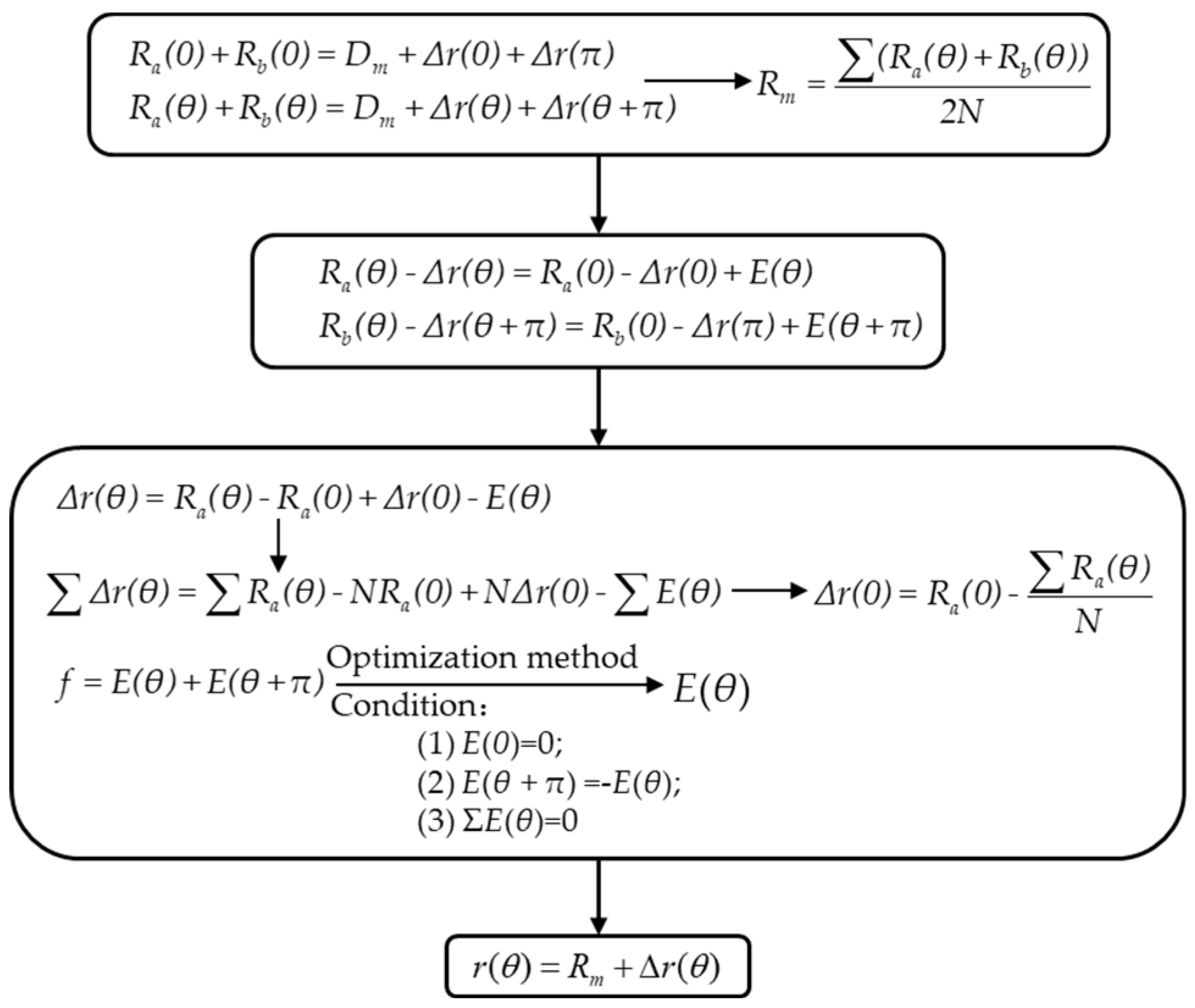
Figure 4.
MZC Processing Flowchart.
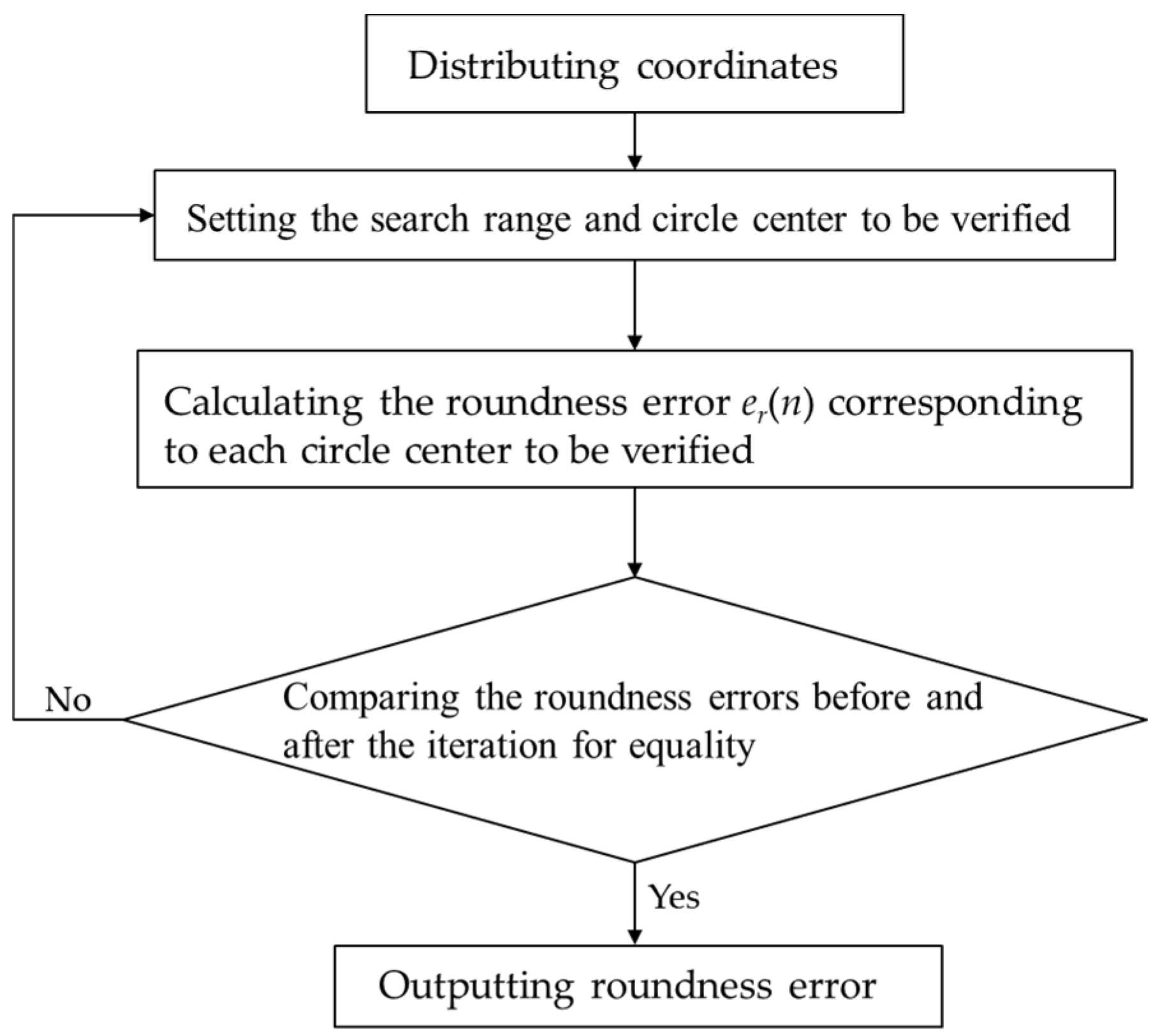
Figure 5.
Tungsten ball under SEM.
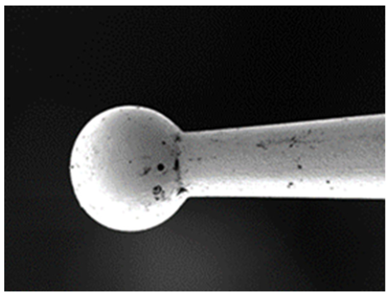
Figure 6.
Force analysis of tungsten ball.
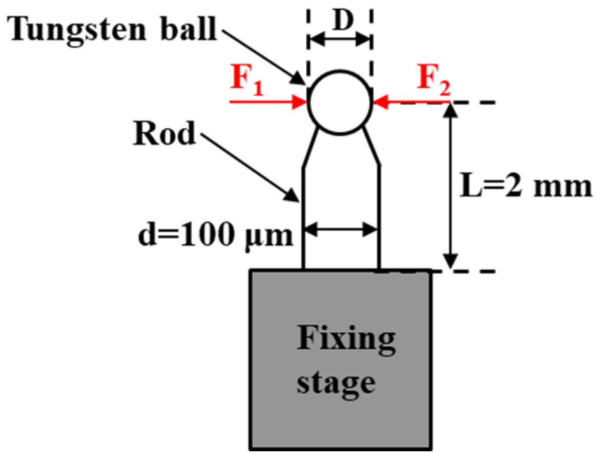
Figure 7.
Structural diagram of elastic mechanism.
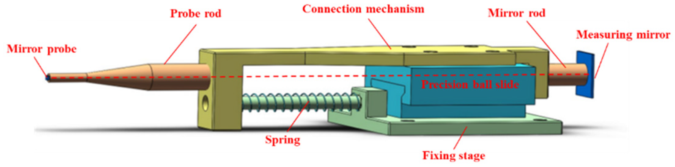
Figure 8.
Elastic mechanism under a preloaded condition.
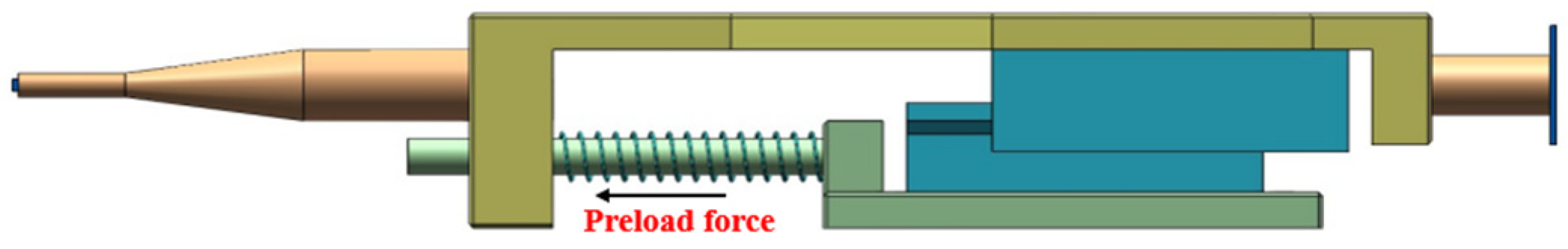
Figure 9.
Physical image of the measurement system.
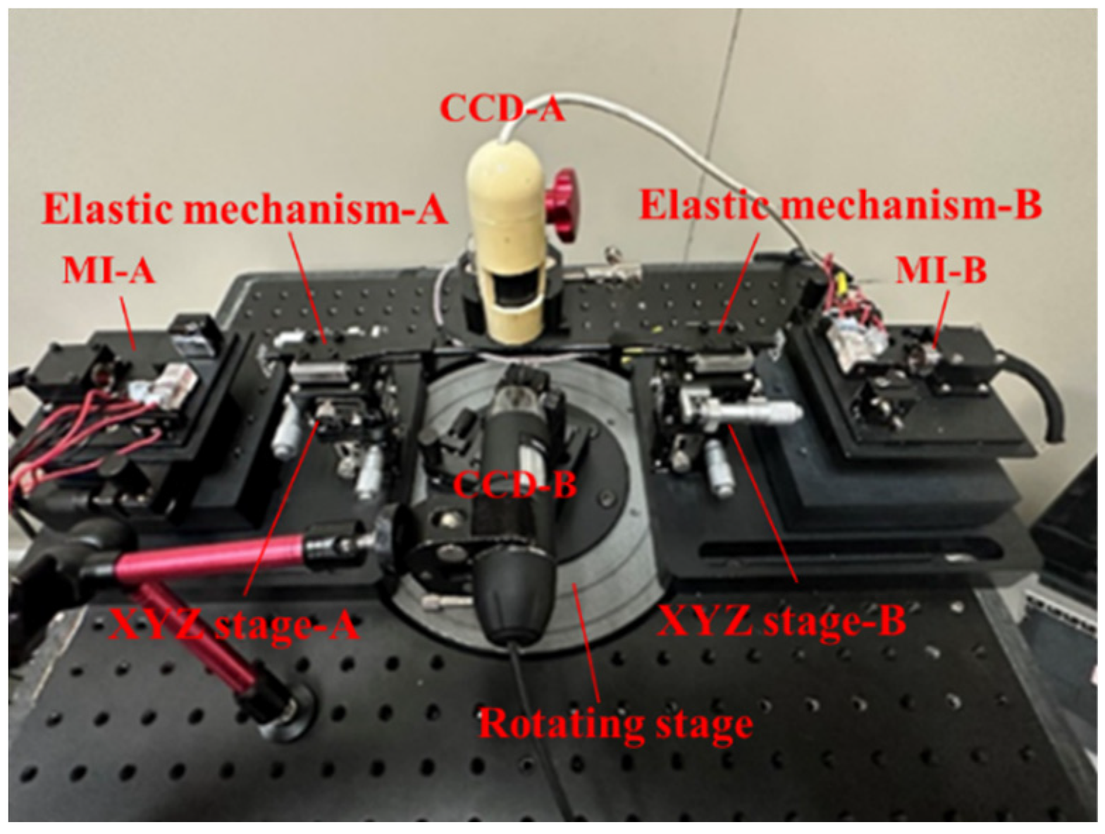
Figure 10.
Tested ruby microsphere.
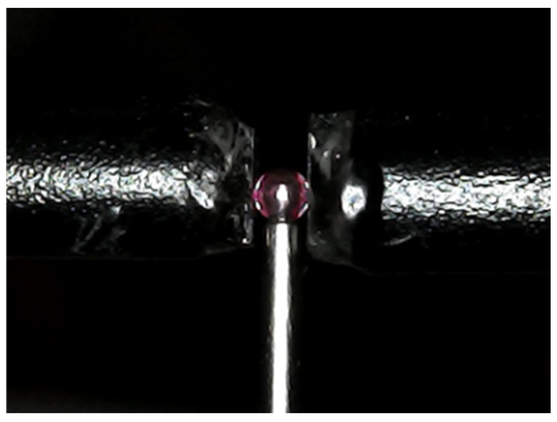
Figure 11.
Circular profile of the microsphere.
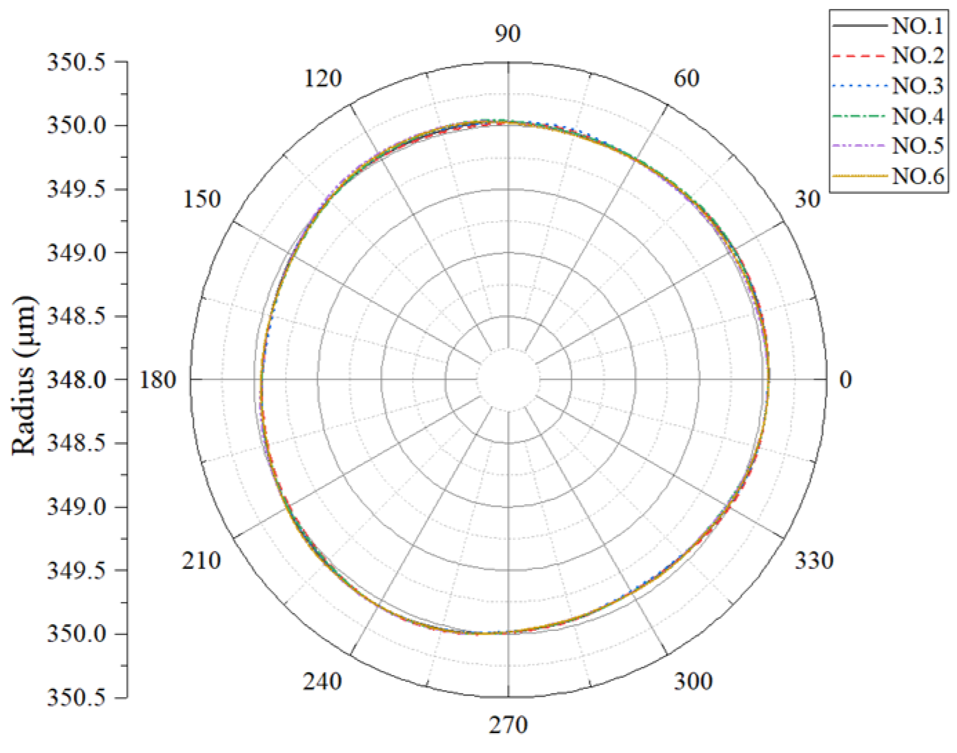
Figure 12.
The tested tungsten ball is mounted on the pedestal.
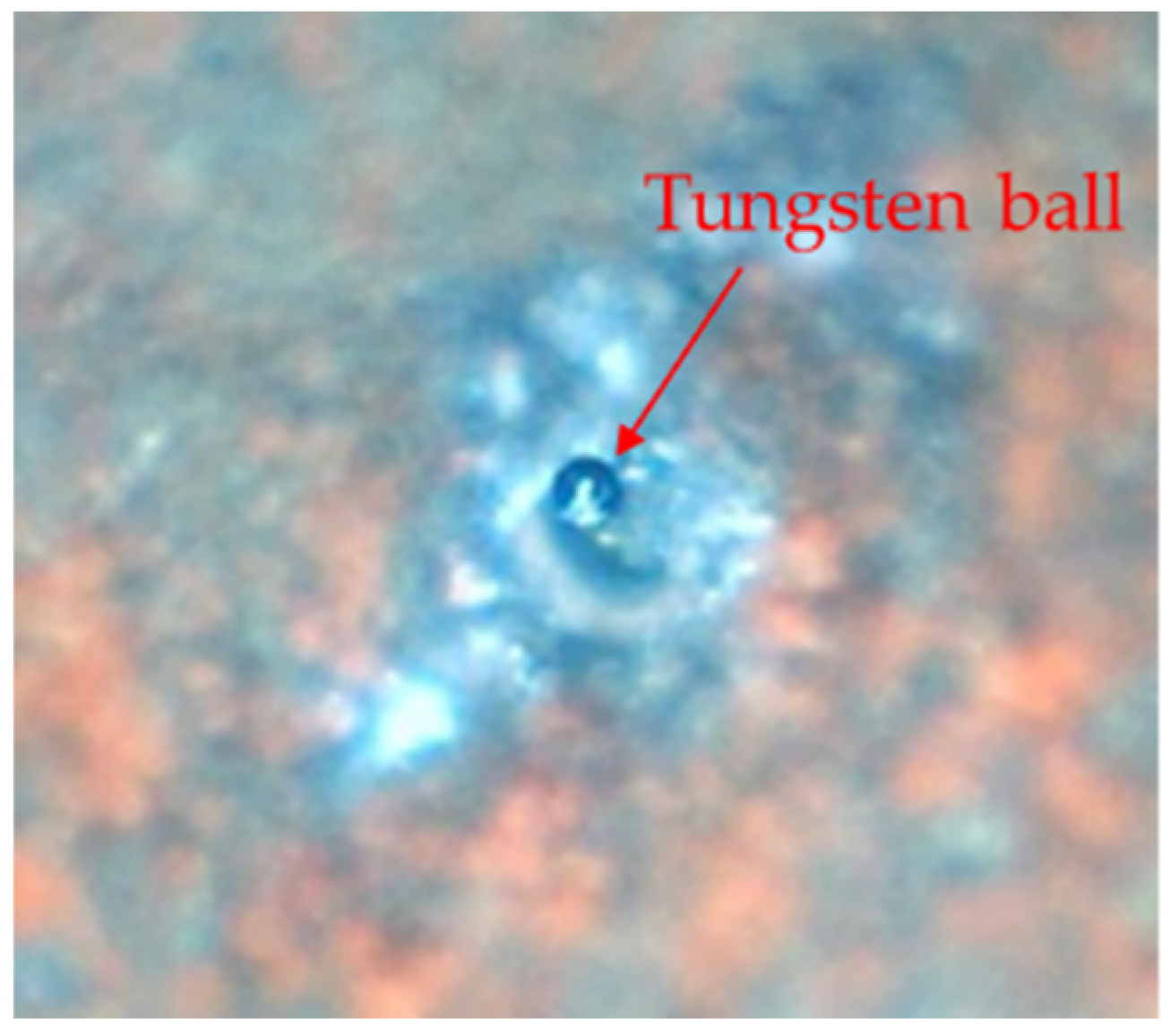
Figure 13.
Circular profile of (a) Tungsten ball-A, (b) Tungsten ball-B.
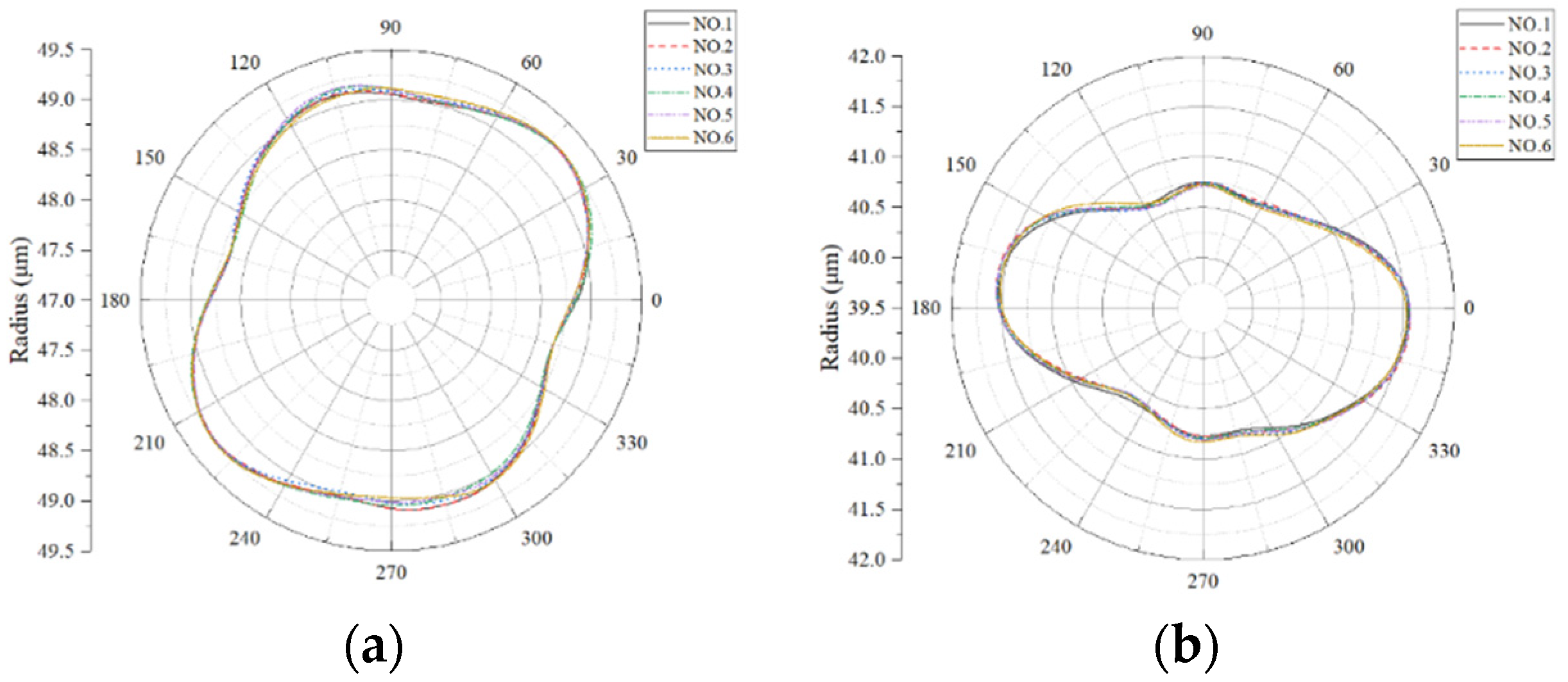

Table 1.
Measurement results of ruby microsphere.
| NO. | rmax (μm) | rmin (μm) | er (nm) | σer(nm) |
|---|---|---|---|---|
| 1 | 350.0506 | 349.9312 | 119.4 | 4.8 |
| 2 | 350.0566 | 349.9302 | 126.4 | |
| 3 | 350.0505 | 349.9204 | 130.1 | |
| 4 | 350.0537 | 349.9336 | 120.1 | |
| 5 | 350.0558 | 349.9319 | 123.9 | |
| 6 | 350.05 | 349.9345 | 115.5 |
Table 2.
Measurement results of two tungsten ball tips.
| Tungsten ball -A | Tungsten ball-B | |||||||
|---|---|---|---|---|---|---|---|---|
| NO. | rmax (μm) | rmin (μm) | er (nm) | σer(nm) | rmax (μm) | rmin (μm) | er (nm) | σer(nm) |
| 1 | 49.2424 | 48.6689 | 573.5 | 6.6 | 41.5442 | 40.6198 | 924.4 | 19.7 |
| 2 | 49.2415 | 48.6732 | 568.3 | 41.5672 | 40.6174 | 949.8 | ||
| 3 | 49.2532 | 48.6763 | 576.9 | 41.5576 | 40.6123 | 945.3 | ||
| 4 | 49.2544 | 48.6682 | 586.2 | 41.5606 | 40.619 | 941.6 | ||
| 5 | 49.2468 | 48.6775 | 569.3 | 41.5644 | 40.6064 | 958.0 | ||
| 6 | 49.2614 | 48.6789 | 582.5 | 41.5300 | 40.6315 | 898.5 | ||
Disclaimer/Publisher’s Note: The statements, opinions and data contained in all publications are solely those of the individual author(s) and contributor(s) and not of MDPI and/or the editor(s). MDPI and/or the editor(s) disclaim responsibility for any injury to people or property resulting from any ideas, methods, instructions or products referred to in the content. |
© 2024 by the authors. Licensee MDPI, Basel, Switzerland. This article is an open access article distributed under the terms and conditions of the Creative Commons Attribution (CC BY) license (https://creativecommons.org/licenses/by/4.0/).
Copyright: This open access article is published under a Creative Commons CC BY 4.0 license, which permit the free download, distribution, and reuse, provided that the author and preprint are cited in any reuse.


