
Submitted:
23 July 2024
Posted:
24 July 2024
You are already at the latest version
Abstract
The research presented in the article is devoted to the study of the influence of phase compounds on the friability of the Fe-Si-Mn-Al complex alloy. The urgency of the problem lies in the development of technology for producing a non-scatterable alloy from manganese-containing ores and high-ash coals. The main goal of the work is to determine the range of alloy compositions and the resulting phases that affect the dispersibility of the alloy, which is critically important for its industrial implementation. Research methods include thermodynamic diagram analysis (TDA) using data on the standard enthalpy of formation of intermetallic compounds, as well as experimental tests in an ore-thermal electric furnace with a capacity of 200 kV*A. The results show that Fe-Si-Mn-Al complex alloys form a variety of silicide and aluminide phases, including intermetallic compounds and ternary systems, which is critical for understanding and controlling their physicochemical properties. When smelting a complex alloy, the content of leboite (Fe3Si7) in the Fe-Si-Mn-Al system plays a significant role. The development of smelting technology will be aimed at avoiding the FeSi2-Fe3Si7-F2(FeAl3Si2)-Mn11Si19 tetrahedron area. This approach to controlling the composition of a complex alloy is critical to ensuring its consistent friability properties in industrial applications. Thus, this work represents an important step in understanding the physical properties and stability of Fe-Si-Mn-Al complex alloys, which have potential for widespread use in metallurgical and other industrial applications.
Keywords:
manganese-containing ore
; high ash coal
; complex alloy
; disintegration
; thermodynamic diagram analysis
; phase composition
; cares
1. Introduction
Complex alloys used for steel processing have a high application potential from the standpoint of reducing costs and improving the quality characteristics of steel products. Treatment of steel deoxidation with alumosilicomanganese (AMS) complex alloy makes it possible to obtain steel with a low content of non-metallic inclusions compared to deoxidation with traditional deoxidizers [1].
Today, scientists from Kazakhstan are actively developing and improving the technology for producing a complex alloy of aluminum-silicon-manganese (AMS) involving substandard manganese-containing ores and high-ash coals. Despite the positive results of many years of research, the industrial development of the smelting of AMS alloy is hampered due to self-destruction and dispersion of the alloy of various chemical compositions.
The AMC alloy first cracks and then crumbles to a powdery state. The main reason for disintegration is considered to be volumetric changes during crystallization of the alloy [2,3]. Researchers [4,5,6,7] indicate that the tendency for the alloy to disintegrate appears with the simultaneous presence of phosphorus (max. 0.048%) and aluminum.
As suggested in [8,9,10,11], there are various reasons for the disintegration of ferroalloys, for example, in ferromanganese - instability of manganese carbide or the presence of aluminum, and in a ferrosilicon alloy - volumetric phase changes during crystallization and formation of the alloy.
Analysis of scientific research works on the study of the physical properties of the alloy (propensity to disintegrate, melting point, density), the authors [2,9,10,11] provide the following data: AMS alloy containing 60-70% manganese, 5-15% silicon, 8- 20% aluminum and carbon from 0.4 to 2%, with a total aluminum and silicon content not higher than ΣSi+Al = 22-23%, are quite strong and at the same time easily crushed, i.e., convenient to use. Alloys with a high total content of aluminum and silicon (>30%) are very fragile. As the carbon content increases, they crumble more easily. The tendency of AMS alloys to crumble decreases when they contain 40-50% manganese, 10-20% silicon, 8-10% aluminum and 0.75-1.0% carbon. The total content of silicon and aluminum was ΣSi+Al = 19-30%. In alloys with a high content of silicon 30-50% and manganese 30-40%, aluminum 10%, carbon 0.6-0.75%, the tendency to disintegration increases with increasing content of silicon and manganese. The phosphorus content in all groups of alloys was 0.1-0.2%. In all the studied alloys, a tendency to disintegration was observed. The disintegration of the AMS alloy was also studied more deeply in the works of Medvedeva G., Takenova T., Radugina V. and Tolstoguzova N. [2,4]. It is indicated that the AMS alloy with a silicon content of more than 30%, aluminum above 3% and phosphorus above 0.05% crumbles into powder when stored in air due to the interaction of phosphides and carbides with air moisture.
An analysis of numerous scientific works by researchers in relation to the AMS alloy shows a negative feature of this alloy - a tendency to self-destruction and further disintegration during cooling and storage.
To identify the causes of self-destruction of individual compositions of the AMS alloy, a complete picture of the relationship between the phase compositions of the alloy depending on the chemical composition is necessary. In this regard, the work carried out a study of the Fe-Si-Mn-Al system using the thermodynamic diagram analysis (TDA) method to determine the set of different phases and compounds depending on the chemical composition. The purpose of carrying out a thermodynamic diagram analysis is to determine the crystallization region of possible crystallizing phases for various alloy compositions. This is important, since the above-mentioned dispersion of the AMS alloy of some compositions and the relatively short shelf life of them negatively affect the implementation of the complex alloy production technology.
2. Materials and Methods
In literary reference books and electronic databases there is a lot of reference data on the Gibbs energies of formation of iron and manganese silicides, iron and manganese aluminides, as well as information on ternary compounds. These data are often contradictory, and for some compounds they are completely absent. The value of ΔG°298 for complex ternary compounds of the metal system Fe-Si-Mn-Al is not available in the literature [12,13,14,15,16,17,18,19,20,21,22,23,24,25,26,27,28].
To reduce the calculation error in this work, in the thermodynamic diagram analysis, instead of ΔG°298, only the values of the enthalpies of formation of intermetallic compounds were used, since in the calculations the influence of the entropies ΔS°298 at standard temperature is insignificant - ranging from 0.53% to 3, 41% (Table 1). Based on this, we believe that using the values of the standard enthalpy of formation will be sufficiently reliable to carry out a thermodynamic diagram analysis of the Fe-Si-Mn-Al system in relation to a temperature of 298 K.
The following systems were considered at a temperature of 298 K: Fe-Si, Fe-Mn, Fe-Al, Mn-Si, Al-Si and Al-Mn [12,13,14,15,16,17,18,19,20,21,22,23,24,25,26,27]. Some phases of double compounds, such as Mn9Si2, Mn11Si19, Mn4Al11, MnAl, as well as ternary compounds of the Fe-Al-Si and Si-Mn-Al system, which are given in the literature, were calculated by us using the method of thermodynamic additivity of enthalpies of similar compounds (marked with «*»).
For example, the value of ΔH°298 (Mn11Si19) is calculated as follows:
ΔH°298 (Mn11Si19) = 8×ΔH°298 (Mn2Si3) - 5×ΔH°298 (MnSi) = 8 × (-164.90) – 5 × (-77.82) =
= -930.1 kJ/mol.
ΔH°298(Fe5Al8Si7) = ΔH°298 (Fe2Al5) + ΔH°298 (FeAl3) + 5×ΔH°298 (FeSi2) - 3×ΔH°298 (FeSi)=
= ((-200.0) + (-111.63) + 5×(-81.17)) – 5 3×(-78.85) = -480.93 kJ/mol
We believe that this method is reliable due to the fact that the calculations used data from the reference database of double compounds [28], which together significantly reduces the level of relative errors.
The breakdown of the Fe-Si-Mn-Al system into a set of stable coexisting triangles of compounds was carried out according to the method described in [29,30], where the method of exchange reactions of 4 closest compounds was used. In this case, the reaction between the components is composed as the sum of two compounds located opposite each other along diagonals from selected four points.
The method for compiling exchange reactions is based on the well-known Hess equation: ∆H°298 reaction = Σ∆H°298 (product) - Σ∆H°298 (starting substance), i.e., the value of the standard enthalpy is equal to the difference between the sum of the enthalpies of the reaction products and the sum of the enthalpies of the starting substances. As a result of calculating the reaction, if the standard enthalpy of the reaction has a positive value, then a line is drawn between the initial components (reaction products are not formed), if the calculation results in a negative value ΔH°298, then the line is drawn between the product - mi reactions. As a result of calculations of possible reactions with the determination of stable paired compounds, the system is divided into many stable triangles of coexisting phases.
An example of calculation of equations is given in relation to the triangulation option for the Fe-Al-Mn system:
2MnAl3 + 4FeAl3 = 2MnAl4 + 2Fe2Al5
ΔHr = (2×(-101.6) + 4×(-111.63)) – (2×(-104.4) + 2×(-200.0)) = 40.92 kJ (draw a stable secant 2MnAl3 + 4FeAl3).
3. Results
The study of the Fe-Si-Mn-Al system is one of the important tasks for obtaining an alloy with specified properties and characteristics, as well as for a correct understanding of the phase composition of the alloy at various ratios of iron, silicon, manganese and aluminum. In the Fe-Si-Mn-Al system under consideration, it is necessary to analyze 6 binary systems: Fe-Si, Fe-Mn, Fe-Al, Mn-Si, Al-Si, Al-Mn and 4 ternary systems: Fe-Si- Al, Si-Mn-Al, Fe-Mn-Si, Al-Mn-Si. All binary systems have been studied by numerous scientists [14,15,16,17,18,19,20,21,22,23,24,25,26,27], and the phase diagrams are detailed.
In the system under consideration, one of the most common systems in the ferroalloy industry is the Fe-Si system. Melts of the Fe-Si system have been widely studied both experimentally and using various model representations. This allows them to be used as basic objects when testing new models and developing new methods for determining the thermodynamic properties of alloys.
More than 70 works of scientists around the world are devoted to the study of the state diagram of the Fe-Si system. In the alloys of the system, the existence of iron-based silicon solid solutions (γ-Fe and α-Fe), as well as intermetallic phases Fe2Si(β), Fe5Si3 (η), FeSi (ε), FeSi2 (NT) and FeSi2 (VT), was discovered. which are presented in review papers [14,15,16,17,18,19,20,21,22,23,24,25,26,27].
In the practical use of ferrosilicon, it was found that alloys containing at least 33.3% silicon are subject to dispersion. All alloys of this composition contain a ξ-phase - leboite, a phase of variable composition with a silicon content in the range of 52-58%, named «Leboit», at the suggestion of Kurnakov, in honor of the French scientist Lebo. This phase has two modifications: a high-temperature modification ξα and a low-temperature modification ξβ, which is similar in composition to the FeSi2 compound, as follows from works [31,32].
It has been established that alloys containing the ξ-phase in the presence of aluminum, phosphorus and calcium additives are subject to disintegration [33]. According to the authors, an important circumstance is that the alloys tend to fracture only in the simultaneous presence of aluminum and phosphorus, which is explained by the ability of aluminum and phosphorus, when dissolved in leboite, to form a quaternary solution of Fe-Si-P-Al. The solution, when exposed to air moisture, disintegrates with the release of hydrogen phosphide.
The decomposition of leboite is accompanied by a significant increase in its volume and is the cause of internal stresses that contribute to the disintegration of ferrosilicon. As the composition of the alloy moves away from the leboite phase (both in the direction of decreasing silicon content and in the direction of increasing it), the resistance of ferrosilicon increases, which is explained by a decrease in the amount of leboite in the alloy.
From the analysis of the phase diagram of the state of the Fe-Si system [14,15,16,17,18,19,20,21,22,23,24,25,26,27], it follows that at a temperature of 298 K there are 5 intermetallic phases in the system: Fe3Si, Fe5Si3, FeSi, FeSi2, Fe3Si. The initial data for the standard enthalpies of the Fe-Si system for thermodynamic diagram analysis are presented in Table 2 (positions 1-5).
The phase diagram of the Fe-Al system is a component of ferrosilicoaluminum and ferroaluminum alloys. A large number of studies have been devoted to the Fe-Al phase diagram [14,15,16,17,18,19,20,21,22,23,24,25,26,27,34,35]. The system includes five stable phases, namely: Fe3Al, FeAl2, FeAl, Fe2Al5, FeAl3 and limited solid solutions on both the Fe and Al sides, each of which has its own homogeneity region (Table 2 (positions 6-10).
A large number of works have been devoted to the Mn-Si phase diagram, as well as the above-mentioned phase diagrams; the most complete data are given in [14,15,16,17,18,19,20,21,22,23,24,25,26,27,36,37,38,39].
There are seven intermetallic phases in the system: of these, Mn5Si3 and MnSi melt congruently at temperatures of 151,2 and 1542 K, respectively, ν(Mn9Si2), Mn3Si, Mn11Si19 are formed by peritectic reactions, R(Mn6Si) and Mn5Si - by peritectoid reactions. In addition, Mn3Si undergoes a polymorphic transformation at a temperature of 950 K.
The initial values of enthalpies of formation for manganese silicides, Mn6Si, Mn9Si2, Mn3Si, Mn5Si3, MnSi, Mn2Si3 and Mn11Si19 were taken from [35] as the most reliable (Table 2, positions 11-17).
The Al-Mn phase diagram is based on the results of the work of scientists given in [14,15,16,17,18,19,20,21,22,23,24,25,26,27,34,40,41,42,43,44,45]. The initial values of the standard enthalpies of formation of manganese aluminides - MnAl6, MnAl4, MnAl3, Mn4Al11, MnAl were taken from [34], as the most reliable ones were selected (Table 2, positions 18-22).
A large number of studies have been devoted to the Al-Si phase diagram, a review of which was made in [14,15,16,17,18,19,20,21,22,23,24,25,26,27,45]. There are no intermetallic compounds in the Al-Si system, and a solid solution is formed throughout the composition. This system belongs to the simple eutectic type with low solubility of the components in each other in the solid state. Numerous results from various studies are in good agreement with each other. At a content of 12.3-12.7% there is a eutectic with a melting point of 850.2 K.
Information on the Fe-Mn phase diagram is given in [14,15,16,17,18,19,20,21,22,23,24,25,26,27] and reviewed in [16]. It has been established that two peritectic invariant transformations occur in the alloys of the system. Calculation of the Fe-Mn phase diagram based on the thermodynamic properties of individual alloys of this system showed its good agreement with the diagram constructed from experimental data [46,47]. There are no chemical intermetallic compounds in the Fe-Mn system.
Ternary compounds in the Fe-Si-Mn-Al system have practically not been studied in relation to complex alloys. Scientific publications regarding this system are mainly devoted to aluminum coal with an aluminum content of more than 75-80%. As noted above, the Fe-Si-Mn-Al metal system consists of 4 ternary systems: Fe-Si-Al, Si-Mn-Al, Fe-Si-Mn, Fe-Mn-Al.
The latest reliable information about Fe-Si-Al is given in the author’s work [48], where a fairly complete review of the compounds of this system was carried out based on data from works [49,50,51]. The author of [48] gives three types of triangulations of the Fe-Si-Al system with the presence of the FeAl3Si2 compound, which the author confirms by performing X-ray phase analysis. In fact, the author of [48] confirmed the presence of the FeAl3Si2 compound in the TCAL database Fe3Al11Si6, which in stoichiometry almost coincides with FeAl3Si2.
Thus, an analysis of the literature data shows that the Fe-Al-Si system contains stable ternary compounds, identified by microstructure and X-ray diffraction methods.
The value of ΔG°298 for ternary compounds of the Fe-Al-Si system is not available in the literature, therefore, instead of the value of the standard Gibbs energy, the values of the standard enthalpy of formation of ternary compounds presented in Table 3 [48] were used in the calculation.
When carrying out triangulation of the Fe-Al-Si subsystem from double state diagrams of Fe-Si, Al-Si, Fe-Al and 7 ternary compounds FexAlySiz twenty-five areas were formed: 1) Si-Fe3Si7-F2; 2) Fe3Si7-FeSi2-F2; 3) FeSi2-FeSi-F2; 4) FeSi-F1-F2; 5) FeSi-F4-F1; 6) F1-F4-F2; 7) FeSi-F3-F4; 8) FeSi-FeAl-F3; 9) FeSi-Fe5Si3-FeAl; 10) Fe5Si3-Fe3Si-FeAl; 11) Fe3Si-Fe3Al-FeAl; 12) Fe3Si-Fe-Fe3Al; 13) FeAl-F6-F3; 14) F3-F4-F6; 15) F4-F5-F2; 16) F5-F6-F2; 17) F6-F7-F2; 18) F4-F6-F5; 19) FeAl-FeAl2-F6; 20) FeAl2-Fe2Al5-F6; 21) Fe2Al5-FeAl3-F6; 22) FeAl3-Al-F6; 23) Al-F7-F6; 24) Al-Si-F7; 25) Si-F2-F7 (Figure 1).
Information about the conditions for the formation and stability of Si-Mn-Al ternary compounds is quite contradictory, and information about the structure obtained by various authors differs both in the number of phases and in the nature of phase equilibria between them [35]. In total, the work considers nine ternary compounds Mn4Al3Si2; Mn3Al3Si2; Mn3Al3Si4; Mn3Al8Si9; Mn4Al9Si3; Mn3Al9Si; Mn3Al12Si; Mn2Al9Si2; Mn3Al15Si2. Of these, in [35] it is indicated that the Mn4Al3Si2 compound can undergo polymorphic transformations leading to cracking of the metal after crystallization, but they do not indicate the recrystallization temperature and the possible mechanism of formation of new compounds.
The value of ΔG°298 for ternary compounds of the Si-Mn-Al system is not available in literature sources, therefore, the values of the enthalpies of formation were used for the calculation. The enthalpy of formation of ternary compounds of the Si-Mn-Al system was determined using the thermodynamic additivity method. The calculated values of the standard enthalpies of formation are given in Table 4.
When triangulating the Si-Mn-Al subsystem from double state diagrams Al-Si, Al-Mn, Mn-Si and 9 ternary compounds MnxAlxSix thirty-one areas were formed: 1) Mn-Mn6Si-MnAl; 2) Mn6Si-Mn9Si2-MnAl; 3) Mn9Si2-Mn3Si-MnAl; 4) Mn3Si-Mn5Si3-MnAl; 5) Mn5Si3-MnSi-MnAl; 6) MnSi-M1-MnAl; 7) MnSi-M3-M1; 8) M3-M2-M1; 9) MnSi-Mn2Si3-M3; 10) Mn2Si3-Mn11Si19-M3; 11) Mn11Si19-Si-M3; 12) Si-M5-M3; 13) Si-M4-M5; 14) Si-MnAl4-M7; 15) Si-M8-M7; 16) Si-M9-M8; 17) Si-Al-M9; 18) M8-M9-M7; 19) Al-M9-M7; 20) Al-M7-MnAl6; 21) MnAl6-M7-MnAl4; 22) M4-М7-MnAl4; 23) MnAl4-M4-M5; 24) MnAl4-M5-M6; 25) MnAl4-M6-MnAl3; 26) MnAl3-M6-M5; 27) MnAl3-M5-M3; 28) MnAl3-M3-M2; 29) MnAl3-M1-M2; 30) MnAl3-M1-MnAl11; 31) Mn4Al11-M1-MnAl (Figure 2).
There is no information about the presence of Fe-Mn-Si ternary compounds. When triangulating the Fe-Mn-Si subsystem, thirteen areas were formed from the double phase diagrams of Fe-Mn, Fe-Si and Mn-Si: 1) Fe-Mn-Mn6Si; 2) Fe-Mn6Si-Mn9Si2; 3) Fe-Mn9Si2-Fe3Si; 4) Fe3Si-Mn9Si2-Mn3Si; 5) Fe3Si-Mn3Si-Mn5Si3; 6) Fe3Si-Mn5Si3-MnSi; 7) Fe3Si-MnSi-Fe5Si3; 8) Fe5Si3-MnSi-FeSi; 9) FeSi-MnSi-Mn2Si3; 10) FeSi-Mn2Si3-Mn11Si19; 11) FeSi- Mn11Si19-FeSi2; 12) FeSi2-Mn11Si19-Fe3Si7; 13) Fe3Si7-Mn11Si19-Si (Figure 3).
There is also no information about the presence of ternary compounds in the Al-Mn-Fe system. When triangulating the Al-Mn-Fe subsystem, eleven areas were formed from the double phase diagrams of Al-Mn, Fe-Mn and Fe-Al: 1) Al-MnAl6-FeAl3; 2) MnAl6-MnAl4-FeAl3; 3) MnAl4-MnAl3-FeAl3; 4) MnAl3-Fe2Al5-FeAl3; 5) MnAl3-FeAl2-Fe2Al5; 6) MnAl3-FeAl-FeAl2; 7) MnAl3-Fe3Al-FeAl; 8) MnAl3-Mn4Al11-Fe3Al; 9) Mn4Al11-MnAl-Fe3Al; 10) MnAl-Fe-Fe3Al; 11) MnAl-Mn-Fe (Figure 4).
Thus, the values of the enthalpy of formation in the Si-Mn-Al ternary system were calculated using the additive method. Binary systems (Fe-Si, Fe-Mn, Fe-Al, Mn-Si, Al-Si, Al-Mn) and ternary (Fe-Si-Al, Si-Mn-Al, Fe-Mn-Si and Al) systems are considered -Mn-Fe) systems.
Based on the tetrahedra of four particular three-component systems Fe-Si-Al, Si-Mn-Al, Fe-Mn-Si and Al-Mn-Fe, a diagram of the phase composition of the four-component system Fe-Si-Mn-Al was constructed (Figure 5). Table 5 presents a list of all elementary triangles of the studied systems.
As a result of calculations, elementary tetrahedra that make up this system were obtained. There are two methods for constructing a phase composition diagram. The first method is geometric, very complex for a given tetrahedron due to the large number of phases formed. As can be seen from Table 5, it consists of 80 stable phase triangles. It is extremely difficult to draw all the connections correctly and not miss or not see the intersection of the boundaries of the triangles. Therefore, one of the methods of closing a triangle onto a tetrahedron was used.
This method consists of searching for triangles that have two identical phases “if two triangles from the nearest triple partial system have two identical phases, then they form a tetrahedron, etc.” According to Table 5, we first consider the first two columns and find triangles that have two identical phases, and write them down. Next, we consider the phase compositions of the second and third columns. We also repeat finding two identical phases, etc. Following this method, fifty-six tetrahedra were obtained.
The breakdown of the general system was carried out for the most part taking into account congruent connections. The sum of the relative volumes of elementary tetrahedra is equal to unity (1.0). Table 6 presents a list of elementary tetrahedra in the Fe-Si-Al-Mn system and their volumes relative to the volume of the original quaternary system, equal to 1 in arbitrary units.
The results of the calculations (Table 6) confirm the reliability of the breakdown of the phase structure diagram of the Fe-Si-Mn-Al system. Figure 6 shows the tetrahedron of the Fe-Si-Al-Mn quaternary system.
Based on the results of TDA and the constructed diagram of the real phase relationships in the Fe-Si-Mn-Al system, two regions of crystallization of leboite (Fe3Si7) were determined - the secondary and primary regions.
The secondary crystallization area of leboite belongs to the tetrahedron – Si-Fe3Si7-Mn11Si19-FeAl3Si2 (Figure 6). Alloys having compositions in this area must be stable. Silicon atoms are primarily crystallized (tmp = 1410°С). Crystallization of leboite (tmp= 1205°С) occurs inside an already formed matrix of silicon crystals. Next, Mn11Si19 crystals begin to fall out (tmp = 1155°С). Recrystallization of leboite according to the scheme Fe3Si7 → 3FeSi2 + Si and an increase in volume by 17% occurs at 940°C. At this temperature, the FeAl3Si2 compound (tmp ˂ 850°С) is in a liquid state. The presence of a framework of silicon crystals and still liquid FeAl3Si2 reduces the effect of internal stress and the increase in volume does not have a significant effect Therefore, with sufficiently rapid cooling, as is common in metallurgical practice, compositional alloys belonging to the Si-Fe3Si7-Mn11Si19-FeAl3Si2, area are not subject to destruction and further disintegration.
The primary crystallization region is characteristic of the region bounded by the FeSi2-Fe3Si7-Mn11Si19- FeAl3Si2 tetrahedron (marked in blue), having a volume of 0.036933 ~ 3.7% (Figure 6). Compositional alloys belonging to this area are unstable and tend to fracture. This range of compositions is characterized by primary crystallization of leboite (tmp = 1205°С). Next, Mn11Si19 (tmp = 1155°С) crystals begin to fall out. Meaning that, the frame of the alloy ingot is formed from Fe3Si7-Mn11Si19 crystals. Recrystallization of leboite at 940°C leads to an increase in internal stress due to an increase in volume, which leads to direct destruction of the ingot framework and the formation of numerous cracks. The formation of cracks in the ingot is the initial effect of destruction. Subsequently, atmospheric moisture interacts with excess phosphorus and calcium-containing phases with the release of gaseous products, which leads to complete disintegration of the alloy ingots.
Consequently, when planning and developing technology for smelting complex alloys based on Fe-Si-Mn-Al, it is necessary to regulate the initial compositions of the charge and the resulting alloy so as not to fall into the region of primary crystallization of leboite (Fe3Si7). The report [27] indicates that the ternary compound Mn4Al3Si2 (M1) has a tendency to polymorphic transformations during crystallization. However, this compound is not in the range of compositions of industrial alloys and was not considered by us.
Experiment
We verified the substantiation of the theoretical data obtained under experimental conditions using a large laboratory ore-thermal electric furnace with a transformer power of 200 kVA. The diameter of the graphite electrode is 150 mm. The electric furnace is two-electrode with a conductive hearth, and one electrode is coked in the hearth with the hearth mass. That is, the electric furnace has a structure similar to the Mige type electric furnace [52,53,54]. The diameter of the furnace bath is 550 mm, the depth of the bath is 400-450 mm. The hearth of the furnace was made of carefully compacted and electrically conductive hearth mass. The transformer is powered by a voltage of 380 V. The electric furnace is equipped with four stages of secondary voltage regulation - from 18.4 to 49 V. The charge cone around the electrode was 0.3-0.45 m at an angle of 35-40°. The electric melting mode was chosen in such a way as to create the necessary temperature conditions in the shaft with deep seating of the electrodes, the current strength on the low side is from 2400 to 2800 A.
Manganese ore, high-ash coal and quartzite were used as raw materials for smelting the AMS alloy. Coke was not used due to the sufficient carbon content of coal.
The technical and chemical composition of the charge materials are presented in Table 7 and Table 8.
Smelting was carried out in a continuous manner, with periodic release of the alloy every 2 hours into cast iron molds. The process is a slag-free process. The charge was uniformly heated by the exhaust reaction gases, which created favorable conditions for the development of reduction processes. The reaction zone was characterized by high temperature, and the metal came out actively. Upon completion of the release of the melt, gases were rapidly released from the tap hole, which indicated the complete release of the metal from the reaction zone, after which fresh charge was loaded into the furnace to form a cone around the electrode [55,56,57,58,59,60].
The process of smelting a complex alloy: the release of the alloy and the formation of a cone from the charge around the electrode of the ore-thermal furnace are presented in Figure 7.
Based on thermodynamic diagram analysis (TDA), we set the expected composition of the charge to obtain a complex AMS alloy with a content of 10-15% Fe; 40-50% Si; 30-40% Mn; 5-12% Al. The preliminary calculation was carried out by the iteration method, which is based on a numerical approximate method for solving technological problems using Microsoft Excel spreadsheets, and the charge was weighed: high-ash coal from the «Saryadyr» deposit - 20 kg; manganese ore from the «Bogach» deposit - 8 kg, quartzite - 2.53 kg. Quartzite was used in the charge mixture to adjust the chemical composition and neutralize residual carbon [61,62].
The resulting alloy of each release was weighed, after which samples were taken for chemical analysis. Chemical analysis of samples (Table 9) was carried out in accordance with GOST-22772.4-77, GOST 22772.6-77, GOST 22772.7-96.
The maximum manganese content in this charge mixture is 40.96% in issue No. 9. The minimum manganese content is 30.2% in samples No. 13 and 14. The unweighted average manganese content in the alloy is 33.65%. Silicon in the alloy varies from 40.14 to 47.8%, the weighted average content is 45.01%. The weighted average content of aluminium in the alloy is 5.23%.
The practical application of the results of thermodynamic analysis to the smelting of the AMS complex alloy comes down to finding elementary tetrahedra within which their compositions are limited. To determine the manufacturability of the resulting alloys during the melting process, their chemical compositions were recalculated to the main elements of the Fe-Si-Mn-Al complex alloy, which are given in Table 10.
The resulting prototypes of melts No. 4-7 and No. 10-18 of the AMS alloy after cooling and storage were stable and did not collapse. Experimental samples of the alloy melts No. 8 and No. 9 were destroyed and subsequently crumbled into fine powder.
4. Discussion
The thermodynamic-diagram analysis of Fe-Si-Mn-Al made it possible to identify the compositional region of the primary crystallization of leboite (Fe3Si7), which is presumably the main cause of destruction of the AMS alloy.
In relation to the Fe-Si-Mn-Al system under consideration, 6 binary systems were analyzed: Fe-Si, Fe-Mn, Fe-Al, Mn-Si, Al-Si, Al-Mn and 4 ternary systems: Fe-Si-Al, Si-Mn-Al, Fe-Mn-Si, Al-Mn-Si. Based on the results of thermodynamic diagram analysis, 80 possible ternary phases were identified.
For the first time, a breakdown of the Fe-Si-Mn-Al system diagram for the solid state involving complex chemical compounds has been carried out: Fe5Al8Si7; FeAl3Si2; Fe3Al3Si2; Fe4Al8Si3; Fe6Al15Si5; Fe4Al12Si3; FeAl4Si; Mn4Al3Si2; Mn3Al3Si2; Mn3Al3Si4; Mn3Al8Si9; Mn4Al9Si3; Mn3Al9Si; Mn3Al12Si; Mn2Al9Si2; Mn3Al15Si2. It was determined that the Fe-Si-Mn-Al system consists of 15 stable tetrahedra.
It has been established that compositional alloys belonging to the region of primary crystallization of leboite (Fe3Si7), namely the tetrahedron FeSi2-Fe3Si7-Mn11Si19-FeAl3Si2, are prone to initial destruction and subsequent disintegration. A possible mechanism for the destruction of alloy ingots during crystallization, which occurs due to an increase in volume and internal stresses of the framework of leboite crystals, is shown.
The results of theoretical studies are confirmed by practical smelting of the AMS alloy in an electric furnace with a transformer power of 200 kVA. The bulk of the melted AMS alloy in composition belongs to the region of the Si-Fe3Si7-F2-Mn11Si9 tetrahedron (V = 0.116 m3), which is the most voluminous in the Fe-Si-Mn-Al system. The resulting alloy samples were stable and did not collapse.
Experimental samples of the alloy (releases № 8-9) collapsed after crystallization and cooling. In composition, they belong to the region of the FeSi2-Fe3Si7-F2-Mn11Si9 tetrahedron, which confirms the possible mechanism of destruction of the AMS alloy that we accepted.
Thus, the theoretical studies carried out using the TDA method for the quaternary system Fe-Si-Mn-Al and experimental tests on the smelting of the AMS alloy made it possible to determine the critical region of the compositions of the AMS alloy, which have a tendency to self-destruct with their further disintegration. The results of the research will allow manufacturers to show interest in introducing and mastering the technology of smelting AMS alloy using manganese ores and high-ash coals and guarantee the production of alloy compositions that are resistant to destruction.
Supplementary Materials
Te datasets generated and/or analysed during the current study are available in the Google Drive repository: https://share.kz/gd3N
Author Contributions
Conceptualization, T.Zh. and A.Ch.; methodology, A.Ch.; software, T.Zh., and A.A.; validation, T.Zh., A.N. and A.Ch.; formal analysis, T.Zh., A.Ch. and Ye.M.; investigation, T.Zh.; resources, T.Zh., B.K., Ye.M. and Ye.K; data curation, T.Zh., and A.A.; writing—original draft preparation, T.Zh.; writing—review and editing, T.Zh., A.N. and A.Ch.; visualization, T.Zh. and A.M.; supervision, T.Zh.; project administration, Z.Zh.; funding acquisition, T.Zh.
Funding
This research was funded by «Qarmet» JSC as part of the co-financing of the funded project: «This research was funded by the Science Committee of the Ministry of Education and Science of the Republic of Kazakhstan (Grant No. AP13268863)».
Data Availability Statement
The data used to support the findings of this study are included within this article.
Conflicts of Interest
The funders had no role in the design of the study; in the collection, analyses, or interpretation of data; in the writing of the manuscript; or in the decision to publish the results.
References
- Gasik M. (ed.). Handbook of ferroalloys: theory and technology. – Butterworth-Heinemann, 2013. [CrossRef]
- Medvedev G.V., Takenov T.D. AMS Alloy. – Alma-Ata: “Nauka” KazSSR, 1979. – 140 p.
- Druinsky M.I., Zhuchkov V.I. Production of complex ferroalloys from Kazakhstan’s mineral raw materials. – Alma-Ata: “Nauka” KazSSR, 1988. – 208 p.
- Radugin V.A., Tolstoguzov N.V., Filatov V.V. On the disintegration of AMS alloy // Improving the production of ferrosilicon at the Kuznetsk Ferroalloy Plant. – Kemerovo: Regional Book Publishing, 1969. – No.2. – pp. 318-327.
- Yakushev A.M., Mikhailov E.N., Kudrin V.A. Investigation of steel deoxidation with complex deoxidizers. In: Steel production and steel casting. - Transactions of the Moscow Evening Metallurgical Institute. Moscow: Metallurgy, 1969, issue 9, pp. 153-170.
- Mikhailov E.N., Yakushev A.M., Kudrin V.A. Efficiency of steel deoxidation with complex deoxidizers // Steel production and steel casting. - 1971. - No.10. - pp. 130-136.
- Purceladze H.G. // Manganese Metallurgy: Abstracts of reports of the All-Union Meeting. - Moscow, 1975. - pp. 41-44.
- Ignatiev V.S., Vikhlevshchuk V.A., Chernogretsky V.M. et al. Study of the properties of ferroalloys and ligatures for microalloying and steel deoxidation // University News. Ferrous Metallurgy. - 198. - No. 6. - pp. 37-42.
- Povolotsky V.D., Komissarova T.A., Minaev V.M. Study of the causes of ferrosilicon disintegration. – 1987. University News. Ferrous Metallurgy. pp. 31-35.
- Tylkina M.A., Savitsky E.M. Phase diagram – the basis for the development of alloys and technological processes. – 1983. Proceedings of the Baikov Institute of Metallurgy. pp. 53-60.
- Zhuchkov V.I., Gasik M.I., Sheshukov O.Yu. Development of rational compositions of ferroalloys for the treatment of steel and cast iron // Collection of reports of the Foundry Conclave No.2 “Theory and practice of metallurgical processes in the production of castings from ferrous alloys” - Chelyabinsk: Chelyabinsk House of Printing, 2007. – 88 p.
- Hansen M., Anderko K. Structure of Binary Alloys. - Moscow: Metallurgizdat, 1962. - Vol. 1,2. - 1988 p.
- Elliott R.P. Structure of Binary Alloys. - Moscow: Metallurgy, 1970. - Vol. 1 – 456 p.; Vol. 2 – 472 p.
- Shank F.A. Structure of Binary Alloys. - Moscow: Metallurgy, 1973. - 760 p.
- Kubaschewski O. Phase Diagrams of Binary Iron Systems. Translated from English / Edited by L.A. Petrova. - Moscow: Metallurgy, 1985. - 184 p.
- Phase Diagrams of Binary and Multicomponent Iron-Based Systems. Handbook / O.A. Bannykh, P.B. Budberg, S.P. Alisova et al. - Moscow: Metallurgy, 1986. - 440 p.
- Kushar L., Repiska L., Lomorova L. et al. // Sb. Vedekych Praci Vysoke Skoly Banske. Ostrava. - 1980.- Vol. 26.- P. 119-136.
- Kuster M. // Trans. Iron Steel Inst. Jap. 1974.- Vol. 14.- No.6. - P. 387-394.
- Gladyshevsky E.M. Crystal Chemistry of Silicides and Germanides. - Moscow: Metallurgy, 1971. - 296 p.
- Phase Diagrams of Binary Metallic Systems / General Editor Lyakishev. - Moscow: Machine Building, 1996. - Vol.1. - 996 p.
- Massalski T.B. Binary Alloy Phase Diagrams. American Society for Metals // Metals Park. Ohio 1986. - 1987. - Vol. 1,2.- 2224 p.
- Massalski, T.B. Binary Alloy Phase Diagrams. American Society for Metals. Metals Park. Ohio 1986. - 1987. - Vol. 1,2. - 2224 p.
- Pearson, W.B. Handbook of Lattice Spacings and Structures of Metals and Alloys. Oxford-London-Edinburgh-New York-Toronto-Sydney-Paris-Braunschweig. // Pergamon Press. - 1967.- 1448 p.
- Villars P., Calvert L.D. Pearson’s Handbook of Crystallographic Data for Intermetallic Phases. Ohio: Metals Park, 1985. - Vol. 1,2,3. - 3258 p.
- Calvert P., L.D. Pearson’s Handbook of Crystallographic Data for Intermetallic Phases. Ohio: Metals Park, 1985. - Vol. 1,2,3. - 3258 p.
- Nash, P. Bull. Alloy Phase Diagrams. 1986. - Vol. 7. - No.6. - P. 601-602.
- Nash, P. Bull. Alloy Phase Diagrams. 1989. - Vol. 10. - No.1. - P. 11-12.
- HSC Chemistry 5.1 Software Package. Outokumpu (Finland). Version 5.1.
- Protsuk A.P., Karapetyants M.Kh. On the thermodynamic study of processes in multicomponent systems // Journal of Applied Chemistry. - 1977. - Vol. 50, No. 1. - pp. 169-175.
- Takenov T.D., Balakirev V.F. Phase trajectory of the process during the reduction of metals from complex oxide systems // Bulletin of the Academy of Sciences of the Kazakh SSR. - 1987. - No. 10. - pp. 58-61.
- Abrikosov, N.Kh. Study of the Fe-Si system in the region of the FeSi2 compound // Proceedings of the Sector of Physico-Chemical Analysis IONKh of the USSR Academy of Sciences. - Moscow. 1956. - Vol. 27. - pp. 157-163.
- Geld P.V., Sidorenko F.A., Shumilov M.A. Study of a-leboite transformations // Physics of Metals and Metallography. - 1960. - Vol. 9. - No. 6. - pp. 861-867.
- Kurnakov N.S., Urazov G.G. Toxic properties of commercial grades of ferrosilicon. - Petrograd: P. P. Soikin’s Printing House, 1914. - 40 p.
- Ryabukhin A.G., Gruba O.N. Enthalpy of formation of silicides of 3d-elements of the periodic system of D.I. Mendeleev. http://dspace.susu.ru/bitstream/handle/0001.74/240/12.pdf.
- Gasik M.I., Lyakishev N.P., Yemlin B.I. Theory and Technology of Ferroalloy Production. Textbook for universities. - Moscow: Metallurgy, 1988. - 784 p.
- Gokhale A.B., Abbaschian R. // Bull. Alloy Phase Diagrams. - 1990. - Vol. 11. - No. 5. - pp. 468-480.
- Okamoto H. // J. Phase Equilibria. - 1991. - Vol. 12. - No. 4. - pp. 505-507.
- Zaitsev A.N., Zemchenko M.A., Mogutnov V.M. // Proceedings of the USSR Academy of Sciences. Metals. - 1990. - Vol. 1. - pp. 207-212.
- Okamoto H. // J. Phase Equilibria. - 1991. - Vol. 12. - No. 4. - pp. 505-507.
- Kono H. // J. Phys. Soc. Japan. - 1958. Vol. 13. - No. 12. - pp. 1444-1451.
- Koster W., Wachtel E. // Z. Metallkunde. 1960. Vol. 51. pp. 271-280.
- Taylor, M.A. // Acta Metall. - 1960. - Vol. 8. - pp. 256-262.
- Koch A.J., Hokkeling P., Steeg M.G., Devos K.J. // J. Appl. Phys. - 1960. - Vol. 31. - No. 5. - pp. 75S-77S.
- Godeske T., Koster W. // Z. Metallkunde. 1971. Vol. 62. No. 10. pp. 727-732.
- Murray J.L., McAlister A.J., Schaefer R.J. et al. // Metall. Trans. A. - 1987. - Vol. 18. - pp. 385-392.
- Dew-Hughes // Calphad. 1979. - Vol. 3. - pp. 175-203.
- Kaufman, L. // Calphad. 1978. - Vol. 2. - No. 2. - pp. 117-146.
- Makaev, T.S. Investigation and development of technology for smelting ferrosilicoaluminum from Ku-Chekin coal deposit raw materials: PhD diss. 6D070900 “Metallurgy” Karaganda, 2020.
- Issagulov A.Z., Chekimbayev A.F., Makaev T.S., Babenko A.A. Studying the Fe-Al-Si system in relation to ferrosilicon-aluminum alloy crystallization. Metalurgija. - ISSN 0543-5846, METABK 59(1) (2020).
- Chekimbayev A.F., Makaev T.S., Babenko A.A. Study of ferrosilicoaluminum alloy disintegration. Materials of the International Scientific and Practical Conference “Innovations in the Field of Natural Sciences as the Basis for Export-Oriented Industrialization of Kazakhstan”. - Almaty. 2019. - pp. 324-327.
- Zi-Kui Liu and Y. Austin Chang // Thermodynamic Assessment of the Al-Fe-Si System: Metall. Trans. – A., 1999, Vol. 30A. - pp. 1081-95. [CrossRef]
- , Yemlin B.I., Druinsky M.I. et al. Reduction processes in ferroalloy production. - 1977. - pp. 219-222.
- Manko V.A., Yemlin B.I., Druinsky M.I. et al. // Technical progress in the electrometallurgy of manganese and silicon ferroalloys. - Dnepropetrovsk, 1975. - pp. 85-88.
- Manko V.A., Yemlin B.I., Druinsky M.I. et al. Ways to improve the technology of ferroalloy smelting in powerful closed electric furnaces: abstracts of reports and communications at the All-Union Conference. - Moscow, 1974. - pp. 100-102.
- Tleugabulov S.M., Nurumgaliev A.Kh. Process of producing the complex alloy // Stal’. – 2005. - No. 7. - pp. 57-59.
- Nurumgaliyev, A., Zayakin, O., Zhuniskaliyev, T., Kelamanov, B., & Mukhambetgaliyev, Y. (2023). Smelting of Fe–Si–Mn–Al Complex Alloy Using High-Ash Coal. Metallurgist, 67(7), 1178-1186. [CrossRef]
- Nurumgaliyev, A., Zhuniskaliyev, T., Shevko, V., Mukhambetgaliyev, Y., Kelamanov, B., Kuatbay, Y., ... & Volokitina, I. (2024). Modeling and development of technology for smelting a complex alloy (ligature) Fe-Si-Mn-Al from manganese-containing briquettes and high-ash coals. Scientific Reports, 14(1), 7456. [CrossRef]
- Mukhambetgaliyev, Y., Zhuniskaliyev, T., & Baisanov, S. (2021). Research of electrical resistance and beginning softening temperature of high-ash coals for melting of complex Alloy. Metalurgija, 60(3-4), 332-334.
- Mukhambetgaliev, E. K., Baisanov, S. O., & Baisanov, A. S. (2013). Improving the process of making alumosilicomanganese. Russian Metallurgy (Metally), 2013(11), 816-819. [CrossRef]
- Mukhambetgaliyev, Y., Baysanov, S., Baysanov, A., Yugay, N., Zhiembaeva, D., & Tolokonnikova, V. (2020). Evaluation of physical and chemical properties of charge materials from the point of possibility of receiving the alloy of alumosilicomanganese. In Proceedings of INFACON XIII-13th International Ferroalloys Congress: Efficient Technologies in Ferroalloy Industry (pp. 317-323).
- Edneral F.P., Filippov A.F. Calculations for the Electrometallurgy of Steel and Ferroalloys. - Moscow: Metallurgizdat, 1956. - 189 p.
- Abdullabekov E.E., Kaskin K.K., Nurumgaliev A.Kh. Technological Calculations for Ferroalloy Production. - Moscow, “Metallurgy”, 2014. - 224 p.
Figure 1.
Phase composition diagram of the Fe-Al-Si subsystem.
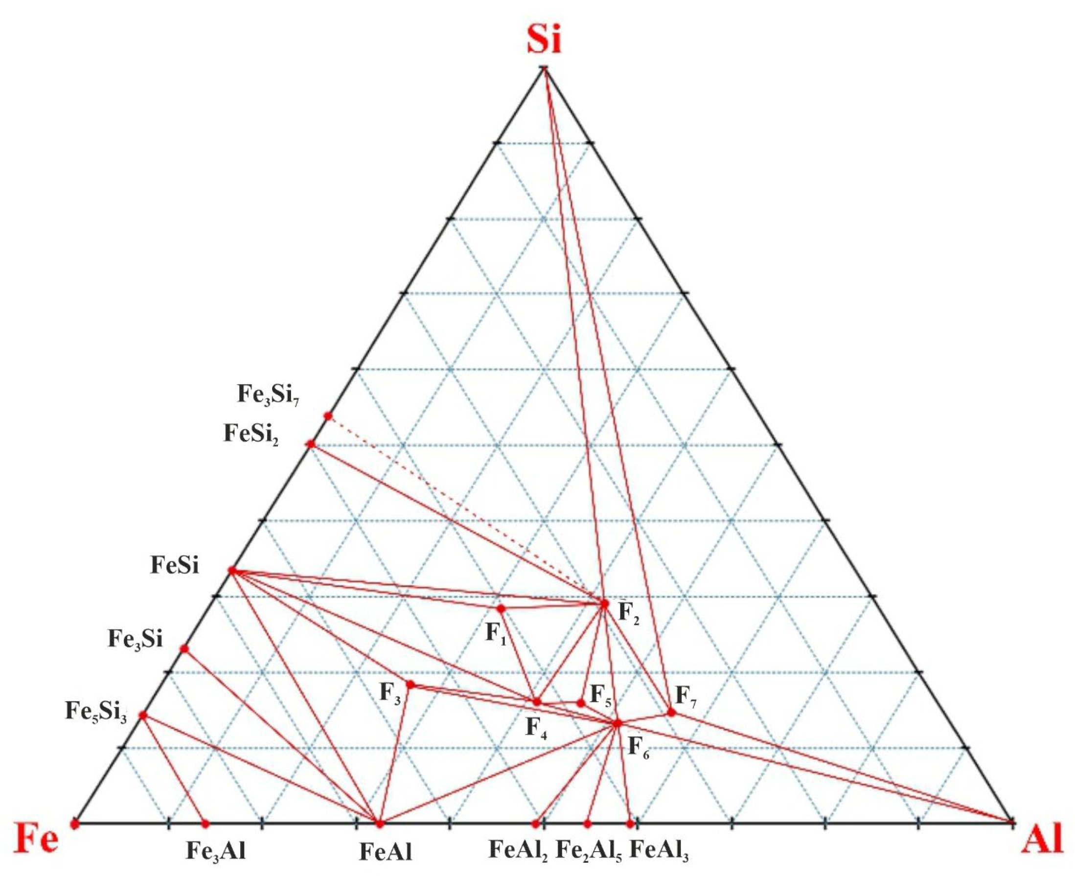
Figure 2.
Diagram of the phase composition of the Si-Mn-Al subsystem.

Figure 3.
Phase composition diagram of the Fe-Mn-Si subsystem.
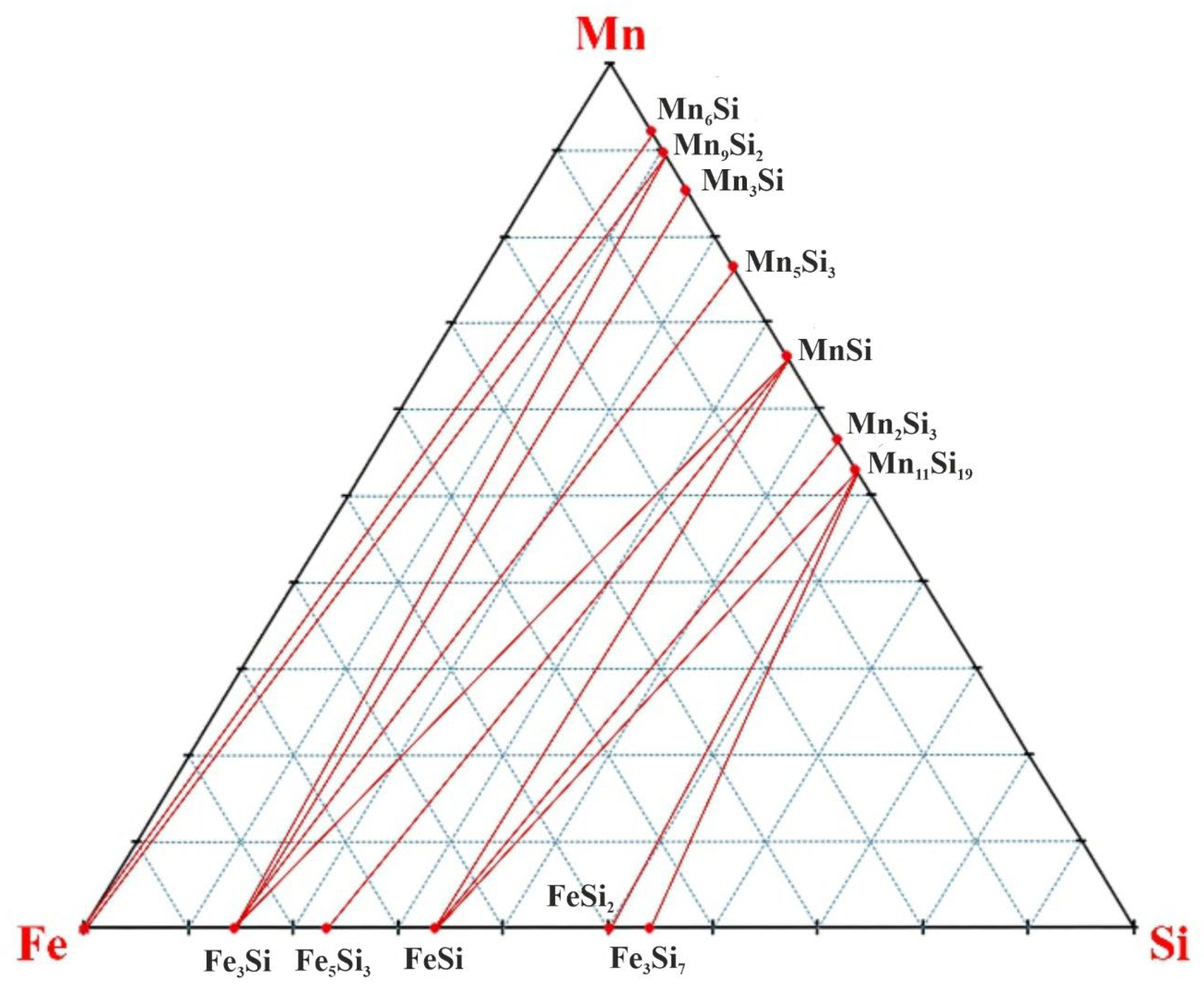
Figure 4.
Phase composition diagram of the Al-Mn-Fe subsystem.

Figure 5.
Diagram of the phase composition of the four-component system Fe-Si-Mn-Al.
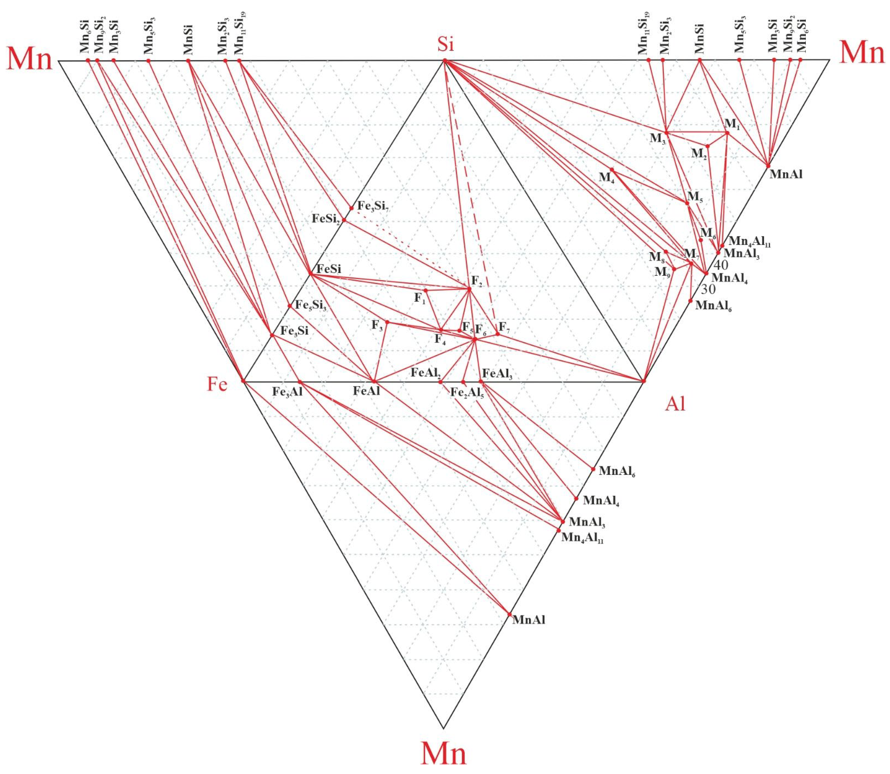
Figure 6.
Phase composition diagram of the Fe-Si-Mn-Al system.
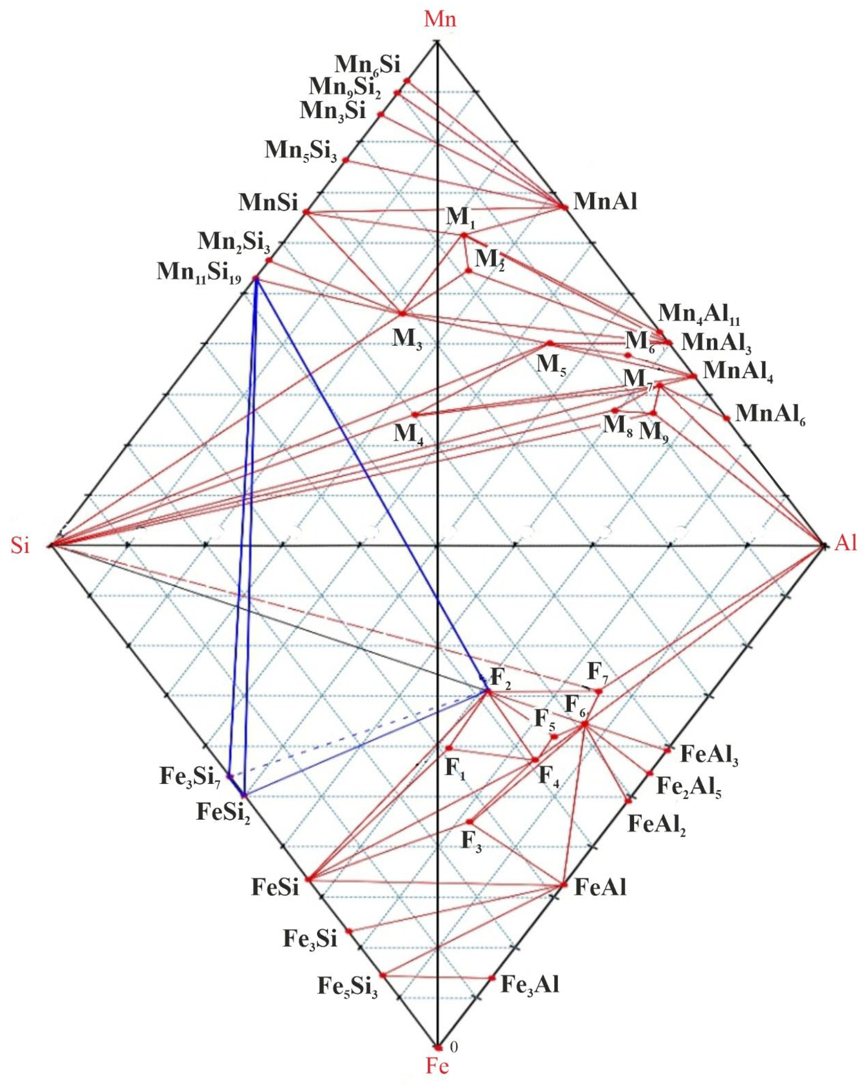
Figure 7.
The process of smelting a complex alloy in an ore-thermal furnace with a transformer power of 200 kVA. a - general view of the ore-thermal furnace; b, c - appearance of the flue.
Figure 7.
The process of smelting a complex alloy in an ore-thermal furnace with a transformer power of 200 kVA. a - general view of the ore-thermal furnace; b, c - appearance of the flue.
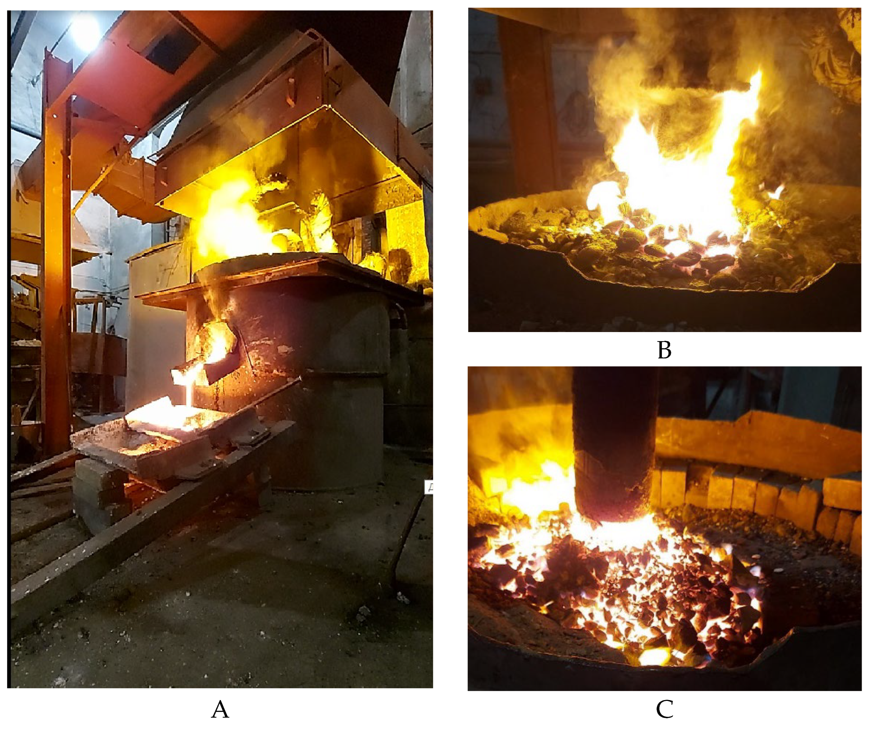

Table 1.
An example of the difference between ΔH°298 and ΔG°298, % [28].
Table 1.
An example of the difference between ΔH°298 and ΔG°298, % [28].
| № | Formula | ΔH°298, kJ/mol | ΔS°298, J/mol |
ΔG°298, kJ/mol |
Difference between ΔH°298 and ΔG°298, % | Melting point |
| 1 | FeSi (66,6/33,3) | -78,85 | 44,685 | -78,430 | 0,53 | 1683 К |
| 2 | FeSi2 (50/50) | -81,17 | 55,647 | -78,405 | 3,41 | 1493 К |
| 3 | Fe3Si (85,7/14,3) | -93,72 | 103,596 | -94,597 | 0,92 | 1813 К |
| 4 | Fe5Si3 (76,9/23,1) | -244,35 | 209,618 | -249,343 | 2,0 | 1373 К |
| № | Formula | Ratio, mass% | ΔН°298, kJ/mole | |||
| Fe | Si | Mn | Al | |||
| 1 | Fe3Si | 85,64 | 14,36 | -93,72 | ||
| 2 | Fe5Si3 | 76,82 | 23,18 | -244,35 | ||
| 3 | FeSi | 66,54 | 33,46 | -78,85 | ||
| 4 | FeSi2 | 50,15 | 49,85 | -81,17 | ||
| 5 | FeSi3 | 53,99 | 46,01 | -154,45 | ||
| 6 | Fe3Al | 86,13 | 13,87 | -62,00 | ||
| 7 | FeAl | 67,42 | 32,58 | -50,21 | ||
| 8 | FeAl2 | 50,86 | 49,14 | -78,45 | ||
| 9 | Fe2Al5 | 45,29 | 54,71 | -200,00 | ||
| 10 | FeAl3 | 40,83 | 59,17 | -111,63 | ||
| 11 | Mn6Si | 7,85 | 92,15 | -101,90 | ||
| 12 | *Mn9Si2 | 10,20 | 89,80 | -322,46 | ||
| 13 | Mn3Si | 14,56 | 85,44 | -123,85 | ||
| 14 | Mn5Si3 | 23,47 | 76,53 | - 200,83 | ||
| 15 | MnSi | 33,83 | 66,17 | -77,82 | ||
| 16 | Mn2Si3 | 43,40 | 56,60 | -164,90 | ||
| 17 | *Mn11Si19 | 46,89 | 53,11 | -981,35 | ||
| 18 | MnAl6 | 25,34 | 74,66 | -110,00 | ||
| 19 | MnAl4 | 33,73 | 66,27 | -104,40 | ||
| 20 | MnAl3 | 40,43 | 59,57 | -101,60 | ||
| 21 | *Mn4Al11 | 42,54 | 57,46 | -358,70 | ||
| 22 | *MnAl | 67,06 | 32,94 | -96,00 | ||
* ΔH°298 – determined by additivity method.
Table 3.
Calculated values of the enthalpy of formation of ternary compounds of the Fe-Al-Si system [48].
Table 3.
Calculated values of the enthalpy of formation of ternary compounds of the Fe-Al-Si system [48].
| № | Formula | Designation | Ratio, mass% | ΔН°298, kJ/mole | ||
| Fe | Al | Si | ||||
| 1 | Fe5Al8Si7 | F1 | 40,37 | 31,21 | 28,42 | -480,93 |
| 2 | FeAl3Si2 | F2 | 28,94 | 41,95 | 29,11 | -190,01 |
| 3 | Fe3Al3Si2 | F3 | 54,99 | 26,57 | 18,44 | 265,28 |
| 4 | Fe4Al8Si3 | F4 | 42,67 | 41,23 | 16,10 | -459,46 |
| 5 | Fe6Al15Si5 | F5 | 38,07 | 45,98 | 15,95 | -670,67 |
| 6 | Fe4Al12Si3 | F6 | 35,38 | 51,28 | 13,34 | -580,78 |
| 7 | FeAl4Si | F7 | 29,11 | 56,25 | 14,64 | -141,40 |
Table 4.
Calculated values of the enthalpy of formation of ternary compounds of the Si-Mn-Al system [35].
Table 4.
Calculated values of the enthalpy of formation of ternary compounds of the Si-Mn-Al system [35].
| № | Formula | Designation | Ratio, mass% | ΔН°298, kJ/mole | ||
| Mn | Al | Si | ||||
| 1 | Mn4Al3Si2 | М1 | 61,58 | 22,68 | 15,74 | -274,52 |
| 2 | Mn3Al3Si2 | М2 | 54,59 | 26,81 | 18,60 | -181,32 |
| 3 | Mn3Al3Si4 | М3 | 46,02 | 22,60 | 31,37 | -351,68 |
| 4 | Mn3Al8Si9 | М4 | 26,02 | 34,08 | 39,90 | -237,5 |
| 5 | Mn4Al9Si3 | М5 | 40,19 | 44,41 | 15,41 | -376,5 |
| 6 | Mn3Al9Si | М6 | 37,82 | 55,73 | 6,45 | -289,42 |
| 7 | Mn3Al12Si | М7 | 31,90 | 62,67 | 5,44 | -297,82 |
| 8 | Mn2Al9Si2 | М8 | 26,87 | 59,39 | 13,74 | -104,92 |
| 9 | Mn3Al15Si2 | М9 | 26,34 | 64,68 | 8,98 | -214,92 |
Table 5.
Quadruple system Fe-Si-Mn-Al.
| Fe-Si-Al | Si-Mn-Al | Fe-Mn-Si | Al-Mn-Fe |
| Si-Fe3Si7-F2 | Mn-Mn6Si-MnAl | Fe-Mn-Mn6Si | Al-MnAl6-FeAl3 |
| Fe3Si7-FeSi2-F2 | Mn6Si-Mn9Si2-MnAl | Fe-Mn6Si-Mn9Si2 | MnAl6-MnAl4-FeAl3 |
| FeSi2-FeSi-F2 | Mn9Si2-Mn3Si-MnAl | Fe-Mn9Si2-Fe3Si | MnAl4-MnAl3-FeAl3 |
| FeSi-F1-F2 | Mn3Si-Mn5Si3-MnAl | Fe3Si-Mn9Si2-Mn3Si | MnAl3-Fe2Al5-FeAl3 |
| FeSi-F4-F1 | Mn5Si3-MnSi-MnAl | Fe3Si-Mn3Si-Mn5Si3 | MnAl3-FeAl2-Fe2Al5 |
| F1-F4-F2 | MnSi-M1-MnAl | Fe3Si-Mn5Si3-MnSi | MnAl3-FeAl-FeAl2 |
| FeSi-F3-F4 | MnSi-M3-M1 | Fe3Si-MnSi-Fe5Si3 | MnAl3-Fe3Al-FeAl |
| FeSi-FeAl-F3 | M3-M2-M1 | Fe5Si3-MnSi-FeSi | MnAl3-Mn4Al11-Fe3Al |
| FeSi-Fe5Si3-FeAl | MnSi-Mn2Si3-M3 | FeSi-MnSi-Mn2Si3 | Mn4Al11-MnAl-Fe3Al |
| Fe5Si3-Fe3Si-FeAl | Mn2Si3-Mn11Si19-M3 | FeSi-Mn2Si3-Mn11Si19 | MnAl-Fe-Fe3Al |
| Fe3Si-Fe3Al-FeAl | Mn11Si19-Si-M3 | FeSi- Mn11Si19-FeSi2 | MnAl-Mn-Fe |
| Fe3Si-Fe-Fe3Al | Si-M5-M3 | FeSi2-Mn11Si19-Fe3Si7 | |
| FeAl-F6-F3 | Si-M4-M5 | Fe3Si7-Mn11Si19-Si | |
| F3-F4-F6 | Si-MnAl4-M7 | ||
| F4-F5-F2 | Si-M8-M7 | ||
| F5-F6-F2 | Si-M9-M8 | ||
| F6-F7-F2 | Si-Al-M9 | ||
| F4-F6-F5 | M8-M9-M7 | ||
| FeAl-FeAl2-F6 | Al-M9-M7 | ||
| FeAl2-Fe2Al5-F6 | Al-M7-MnAl6 | ||
| Fe2Al5-FeAl3-F6 | MnAl6-M7-MnAl4 | ||
| FeAl3-Al-F6 | M4-М7-MnAl4 | ||
| Al-F7-F6 | MnAl4-M4-M5 | ||
| Al-Si-F7 | MnAl4-M5-M6; | ||
| Si-F2-F7 | MnAl4-M6-MnAl3 | ||
| MnAl3-M6-M5 | |||
| MnAl3-M5-M3 | |||
| MnAl3-M3-M2 | |||
| MnAl3-M1-M2 | |||
| MnAl3-M1-MnAl11 | |||
| Mn4Al11-M1-MnAl |
Table 6.
List of elementary tetrahedra in the Fe-Si-Mn-Al system and their volumes relative to the volume of the original quaternary system, equal to 1 in arbitrary units.
Table 6.
List of elementary tetrahedra in the Fe-Si-Mn-Al system and their volumes relative to the volume of the original quaternary system, equal to 1 in arbitrary units.
| № | Tetrahedrons | Volume | № | Tetrahedrons | Volume |
| 1 | Si-Fe3Si7-F2-Mn11Si19 | 0,116356 | 29 | Fe3Si-Mn3Si-MnAl-Mn5Si | 0,025065 |
| 2 | FeSi2-Fe3Si7-F2-Mn11Si19 | 0,008677 | 30 | Fe3Si-Mn3Si-MnAl-MnSi | 0,059887 |
| 3 | FeSi2-FeSi-F2-Mn11Si19 | 0,036933 | 31 | Fe3Si-M1-MnAl-MnSi | 0,014704 |
| 4 | F1-FeSi-F2-M3 | 0,003658 | 32 | Fe3Si-M1-M3-MnSi | 0,030352 |
| 5 | F1-FeSi-F4-M3 | 0,015307 | 33 | M3-M2-M1-Fe3Si | 0,005535 |
| 6 | F1-F2-F4-M3 | 0,006422 | 34 | MnSi-Mn2Si3-M3-FeSi | 0,014428 |
| 7 | FeSi-F3-F4-MnAl3 | 0,006435 | 35 | Mn11Si19-Mn2Si3-M3-FeSi | 0,00526 |
| 8 | FeSi-F3-FeAl-MnAl3 | 0,016113 | 36 | Mn11Si19-Si-M3-F7 | 0,034922 |
| 9 | FeSi-Fe5Si3-FeAl-MnSi | 0,049261 | 37 | M5-Si-M3-F7 | 0,032996 |
| 10 | Fe3Si-Fe5Si3-FeAl-MnSi | 0,095044 | 38 | M5-Si-M4-F7 | 0,006298 |
| 11 | Fe3Si-Fe3Al-FeAl-MnAl4 | 0,009075 | 39 | Si-M4-M7-F7 | 0,015784 |
| 12 | Fe3Si-Fe3Al-Fe-MnAl | 0,013431 | 40 | Si-M8-M7-F7 | 0,006059 |
| 13 | FeAl-F6-F3-MnAl3 | 0,017125 | 41 | Si-M8-M9-F7 | 0,005186 |
| 14 | F4-F6-F3-MnAl3 | 0,000713 | 42 | M7-M8-M9-F7 | 0,000829 |
| 15 | F4-F5-F2-M3 | 0,002896 | 43 | Al-M8-M9-F7 | 0,00344 |
| 16 | F6-F5-F2-M3 | 0,002709 | 44 | Al-M-MnAl6-F7 | 0,003976 |
| 17 | F6-F7-F2-M3 | 0,004219 | 45 | MnAl6-M7-MnAl4-FeAl3 | 0,001851 |
| 18 | F4-F6-F5-M3 | 0,000572 | 46 | M4-M7-MnAl4-F7 | 0,00088 |
| 19 | FeAl-F6-FeAl2-MnAl3 | 0,008866 | 47 | M4-M5-MnAl4-F7 | 0,010998 |
| 20 | Fe2Al5-F6-FeAl2-MnAl3 | 0,003009 | 48 | M6-M5-MnAl4-F7 | 0,000627 |
| 21 | Fe2Al5-F6-FeAl3-MnAl3 | 0,002418 | 49 | M6-MnAl3-MnAl4-FeAl3 | 0,00175 |
| 22 | Al-F6-FeAl3-MnAl6 | 0,013729 | 50 | M6-MnAl3-M5-F7 | 0,001128 |
| 23 | F7-F6-MnAl6-Al | 0,003284 | 51 | M3-MnAl3-M5-F3 | 0,005089 |
| 24 | F7-Si-M9-Al | 0,084923 | 52 | M3-MnAl3-M2-Fe3Si | 0,029251 |
| 25 | F7-Si-M3-F2 | 0,018758 | 53 | M1-MnAl3-M2-Fe3Si | 0,01467 |
| 26 | Fe-Mn6Si-MnAl-Mn | 0,025991 | 54 | M1-MnAl3-Mn4Al11-Fe3Al | 0,002839 |
| 27 | Fe-Mn6Si-MnAl-Mn9Si | 0,007567 | 55 | M1-MnAl-Mn4Al11-Fe3Al | 0,033254 |
| 28 | Fe3Si-Mn3Si-MnAl-Mn9Si | 0,012391 | 56 | Fe-MnAl-Fe3Si-Mn9Si2 | 0,04706 |
| Итoгo | 1,0000 | ||||
Table 7.
Technical composition of high-ash coal from the «Saryadyr» deposit.
| Aс | Vг | Wт | Cтв |
| 50,04 | 19,28 | 1,98 | 31,86 |
Table 8.
Chemical composition of charge materials.
| Material | Fe2O3 | SiO2 | Al2O3 | MnO2 | CaO | MgO | TiO2 | P2O5 | S | p.l. |
| Mn ore | 5,72 | 6,27 | 0,72 | 49,94 | 15,05 | 0,83 | 0,02 | 0,01 | 21,44 | |
| Coal ash | 5,79 | 66,36 | 20,7 | 2,64 | 3,46 | 1,01 | 0,035 | 0,005 | ||
| Quartzite | 0,52 | 95,57 | 0,24 | 0,12 | 0,01 | 3,54 |
Table 9.
Chemical composition of complex AMS alloys of experimental melts.
| № of heating | Fe | Si | Al | Mn | Ca | C | S | P |
| 4 | 12,3 | 44,1 | 2,5 | 31,3 | 5,7 | 0,5 | 0,01 | 0,06 |
| 5 | 10,8 | 45,4 | 3,4 | 32,2 | 5,3 | - | - | - |
| 6 | 11,3 | 46,1 | 2,9 | 33,8 | 4,26 | - | - | - |
| 7 | 11,7 | 45 | 3,8 | 32,1 | 6,2 | 0,5 | 0,013 | 0,09 |
| 8 | 11,1 | 44,9 | 2,2 | 36,4 | 4,7 | - | - | - |
| 9 | 10,82 | 41,75 | 2,5 | 40,96 | 3,2 | - | - | - |
| 10 | 9,8 | 46,7 | 3,3 | 32,8 | 3,6 | 0,5 | 0,015 | 0,08 |
| 11 | 8,1 | 46,8 | 5,8 | 32,6 | 4,8 | - | - | - |
| 12 | 10,2 | 47,8 | 8 | 31,1 | 2,8 | - | - | - |
| 13 | 10,1 | 47,5 | 7,9 | 30,2 | 3,2 | 0,3 | 0,02 | 0,07 |
| 14 | 9,2 | 47,3 | 9,7 | 30,2 | 2,26 | - | - | - |
| 15 | 10,2 | 44,3 | 8,3 | 32,6 | 3,8 | - | - | - |
| 16 | 10,3 | 43,9 | 9,2 | 35,1 | 0,9 | 0,5 | 0,013 | 0,08 |
| 17 | 14,13 | 40,14 | 3,2 | 38,62 | 3,2 | - | - | - |
| 18 | 10,2 | 43,5 | 5,7 | 34,7 | 5,5 | - | - | - |
| Σav. | 10,68 | 45,01 | 5,23 | 33,65 | 4,26 | 0,45 | 0,013 | 0,073 |
Table 10.
Chemical composition of the complex master alloy of experimental melts.
| № of heating | Fe | Si | Al | Mn | Tetrahedron | Volume |
| 4 | 13,64 | 48,89 | 2,77 | 34,70 | Si-Fe3Si7-F2-Mn11Si9 | 0,116356 |
| 5 | 11,76 | 49,46 | 3,70 | 35,08 | ||
| 6 | 12,01 | 48,99 | 3,08 | 35,92 | ||
| 7 | 12,63 | 48,60 | 4,10 | 34,67 | ||
| 8 | 11,73 | 47,46 | 2,33 | 38,48 | FeSi2-Fe3Si7-F2-Mn11Si9 | 0,008677 |
| 9 | 11,27 | 43,48 | 2,60 | 42,65 | ||
| 10 | 10,58 | 50,43 | 3,56 | 35,42 | Si-Fe3Si7-F2-Mn11Si9 | 0,116356 |
| 11 | 8,68 | 50,16 | 6,22 | 34,94 | ||
| 12 | 10,50 | 49,23 | 8,24 | 32,03 | ||
| 13 | 10,55 | 49,63 | 8,25 | 31,56 | ||
| 14 | 9,54 | 49,07 | 10,06 | 31,33 | ||
| 15 | 10,69 | 46,44 | 8,70 | 34,17 | ||
| 16 | 10,46 | 44,57 | 9,34 | 35,63 | ||
| 17 | 14,70 | 41,77 | 3,33 | 40,19 | Mn11Si9-Mn2Si3-M3-FeSi | 0,00526 |
| 18 | 10,84 | 46,23 | 6,06 | 36,88 | Si-Fe3Si7-F2-Mn11Si9 | 0,116356 |
Disclaimer/Publisher’s Note: The statements, opinions and data contained in all publications are solely those of the individual author(s) and contributor(s) and not of MDPI and/or the editor(s). MDPI and/or the editor(s) disclaim responsibility for any injury to people or property resulting from any ideas, methods, instructions or products referred to in the content. |
© 2024 by the authors. Licensee MDPI, Basel, Switzerland. This article is an open access article distributed under the terms and conditions of the Creative Commons Attribution (CC BY) license (http://creativecommons.org/licenses/by/4.0/).
Copyright: This open access article is published under a Creative Commons CC BY 4.0 license, which permit the free download, distribution, and reuse, provided that the author and preprint are cited in any reuse.


