
Submitted:
20 July 2024
Posted:
22 July 2024
You are already at the latest version
Abstract
Hydrogen sulfide is present in active or extinct volcanic areas (mofettas). The habitable premises in these areas are affected by the presence of hydrogen sulfide, which, even in low concentrations, gives off a bad to unbearable smell. If the living spaces considered are closed enclosures, then a system can be designed to reduce the concentration of hydrogen sulfide. This paper presents a membrane way to reduce the hydrogen sulfide concentration to acceptable limits using a cellulosic derivative-propylene hollow fiber based composite membrane module. The cellulosic derivatives considered were carboxymethyl–cellulose (NaCMC), cellulose acetate (CA), methyl 2–hydroxyethyl–cellulose (MHEC), and 2–hydroxyethyl–cellulose (HEC). In the permeation module, hydrogen sulfide is captured with a solution of cadmium that forms cadmium sulfide, usable as a luminescent substance. The composite membranes were characterized by SEM, EDAX, FTIR, FTIR 2D maps, thermal analysis (TG and DSC) and from the perspective of hydrogen sulfide air removal performance. To determine the process performances, the variables were: the nature of the cellulosic derivative–polypropylene hollow fiber composite membrane, the concentration of hydrogen sulfide in the polluted air, the flow rate of polluted air, and the pH of the cadmium nitrate solution. Pertraction efficiency was maximum for the sodium carboxymethyl–cellulose (NaCMC)-polypropylene hollow fiber membrane, a hydrogen sulfide concentration in the polluted air of 20 ppm, polluted air flow rate of 50 L/min, and a pH of 2 and 4.
Keywords:
hydrogen sulfide separation
; polluted air
; composite membranes
; sodium carboxymethyl–cellulose
; cellulose acetate
; methyl 2–hydroxyethyl–cellulose
; 2–hydroxyethyl–cellulose
1. Introduction
Among the nonmetal hydrides (NMHn) only water is liquid and, of course, non-toxic. The other hydrides of non-metals are gases with variable toxicity [1,2,3]. Of these, hydrogen sulfide is particularly important, which can appear in the environment both naturally (active or extinct volcanoes) [4,5,6,7] and as a result of human activity [8,9,10,11,12,13,14,15]. Among the sources originating from human activities, most notable are: anaerobic decomposition [8], fertilizers nitrogenous [9], treatment plants [10], effluents treatment plants [11], dye and dye intermediates, [12], sugar and distillery [13], pesticides [14] and pulp and paper limekiln [15].
Hydrogen sulfide is undesirable both in industrial processes (corrosion being the main cause) [16,17] and in contact with humans (toxicity being predominant) [18,19,20].
One of the ways of interpreting the effect of hydrogen sulfide in contact with humans is shown in Figure 1 [21,22].
Considering the undesirable action both on industrial installations and on humans, researchers have focused on the elimination of hydrogen sulfide or its derivatives (mercaptans, thiophene etc.) from various gaseous or liquid environments [23,24,25].
There are various ways of removing hydrogen sulfide: absorption [26], adsorption [27], electrochemical degradation [28], photochemical degradation [29], catalytic degradation [30] or biodegradation [31,32,33]. All the presented elimination processes are non-regenerative, and the resulting products are: sulfur, in reductive processes, and sulfur oxides in oxidative processes [34,35].
One of the ways to remove hydrogen sulfide is represented by membrane processes, which can be reducing or oxidizing, but also recuperative, hydrogen sulfide being fixed in compounds with practical utility [36,37,38,39,40,41,42]. Membrane techniques use polymeric [43], inorganic [44], composite [45] or liquid [46,47,48] membranes.
The applications of membrane and membrane techniques are in continuous development, being applied both in the separation processes of dispersed systems and gas mixtures [49,50,51,52,53,54]. In the last decade biopolymers such as chitosan or cellulosic derivatives present in various composite membranes are tested in sulfur gas separation processes [55,56,57,58].
In this paper, we start from the results obtained previously and study composite polypropylene hollow fiber–cellulosic derivatives (sodium carboxymethyl–cellulose, cellulose acetate, 2–methyl–hydroxyethyl–cellulose and hydroxy–ethyl–cellulose), hydrogen sulfide is recuperatively separated from the gas mixture, being fixed as cadmium sulfide in the composite membrane module.
2. Materials and Methods
2.1. Materials
The materials used in the present work were of analytical purity. They were purchased from Merck (Merck KGaA, Darmstadt, Germany): Cd (NO3)2 tetrahydrate (308.48 g/mol), dimethyl formamide (DMF), sodium sulfide (Na2S) [78.0452 g/mol (anhydrous)], hydrogen sulfide, sodium hydroxide, and nitric acid [58].
The cellulosic derivatives–sodium carboxymethyl–cellulose (NaCMC), cellulose acetate (CA), methyl 2–hydroxyethyl–cellulose (MHEC), and 2–hydroxyethyl–cellulose (HEC) (Table 1) [59] were purchased from Sigma-Aldrich (Merck KGaA, Darmstadt, Germany).
The tubular dialysis membranes were provided by Visking (Medicell Membranes Ltd., London, UK) [57].
An MQuant® sulfide test (Merck Millipore from Merck KGaA, Darmstadt, Germany), and a Sulfide Test photometric Spectroquant® (Merck KGaA, Darmstadt, Germany) were used [58].
The hollow fibers polypropylene support membranes (PPSM) were provided by GOST Ltd., Perugia, Italy [60].
2.2. Preparation of Cellulosic Derivatives–Polypropylene Hollow Fiber Membrane
The cellulosic derivatives (NaCMC, CA, MHEC, and HEC) with the characteristics indicated in Table 1, were solubilized in a mass concentration of 4%, in dimethylformamide without traces of water. For this, the glass vessel, in which the dimethylformamide and the corresponding amount of polymer were introduced, is closed tightly (the possibility of absorbing water vapor from the working atmosphere is eliminated) is placed in an ultrasonic bath (Elmasonic S, Elma Schmidbauer GmbH, Singen, Germany) for 24 hours, thus observing the complete solubilization and obtaining the polymeric dispersion [63]. The obtained solutions are subjected to centrifugation, then they are kept in closed glass vessels for 24 hours to remove bubbles.
Obtaining cellulosic derivatives–polypropylene hollow fibers composite membranes is carried out in the module shown in Figure 2 [64], as follows:
- The solution of cellulosic derivative in dimethylformamide (DMF) is introduced through the outside of the polypropylene hollow fibers in the membrane module (MM);
- Water is introduced through the inside of the polypropylene hollow fibers;
- The two phases are contacted in the membrane module resulting in the composite membrane by phase inversion [61], cellulosic derivative dispersion in DMF and aqueous DMF solution;
- After carrying out the obtaining procedure, the membranes are washed with pure water, by introducing water between the cellulosic derivative-polypropylene hollow fibers composite membranes;
- Four types of composite membranes were obtained, symbolized as in Table 1 (P1, P2, P3 and P4).
2.3. Permeation Procedures
The composite membranes thus obtained were characterized by scanning electron microscopy (SEM), Energy Dispersive X–ray Spectroscopy (EDAX), thermal analysis (TG and DSC), Fourier Transform Infra-Red spectroscopy (FTIR) and FTIR 2D maps, being prepared for the permeation tests of the air – hydrogen sulfide gas system (Figure 3) [58].
The separation installation of hydrogen sulfide from air (Figure 3) works like this:
- The gaseous mixture is made by dispersing hydrogen sulfide coming from a source that allows a precision dosing of ±0.1% in volumetric percentages, by mixing with air dosed in the specific bottle;
- After mixing, the air containing hydrogen sulfide is homogenized by passing through a 5.0 m serpentine (6) and slows down in chamber 7;
- The air polluted with hydrogen sulfide is introduced into the permeation module (1) through the composite membranes (2);
- The cadmium nitrate solution (receiving phase) is introduced through the outside of the composite membranes using pump 3;
- Separators 4 and 5 collect any gaseous mixture that will be captured in hatch 8 with sodium hydroxide.
The pertraction efficiency (PE%) for the species of interest (hydrogen sulfide) using the concentration of the solutions [65] was calculated as follows, equation (1):
𝑃𝐸(%) = (𝑐0−𝑐𝑓)/𝑐0×100,
cf being the final concentration of the solute (hydrogen sulfide) and c0 the initial concentration of solute (hydrogen sulfide).
The measurements were made using MQuant® sulfide test (Merck Millipore from Merck KGaA, Darmstadt, Germany), and Sulfide Test photometric Spectroquant® (Merck KGaA, Darmstadt, Germany) [57].
The measurements were independently validated using an Oldham MX 21 gas detector (MX 21 Plus Multigas, Arras, France) equipped with electrochemical sensors, and a H2S Model 3000RS Analyzer (MultiLab LLC, Bucharest, Romania) [58].
After retaining the hydrogen sulfide in the cadmium solution following the permeation of the polluted air with hydrogen sulfide on the P1 membrane, the cadmium sulfide membrane (P5) is obtained. Wet cadmium sulfide is recovered from the composite membranes resulting in sample P6.
2.4. Equipment
The microscopy studies, scanning electron microscope (SEM) and high-resolution SEM (HR SEM), were performed using a Hitachi S4500 system (Hitachi High-Technolo- gies Europe GmbH, Mannheim, Germany) [66].
Thermal characterizations were carried out using a Netzsch STA 449C Jupiter apparatus (NETZSCH-Gerätebau GmbH, Selb, Germany) [62].
Spectroscopy Bruker Tensor 27 FTIR with a Diamond Attenuated Total Reflection- ATR (Bruker) was used for spectrometric study in the range of 500 to 4000 cm−1 [59].
FTIR 2D maps were recorded with a Nicolet iS50R FTIR microscope and Nicolet iZ10 Module Part (Thermo Fisher Scientific Inc., Waltham, MA, USA), with DTGS detector, in the wavenumber range 4000–600 cm−1 [67].
UV-VIS analysis was performed on a Spectrometer CamSpec M550 (Spectronic CamSpec Ltd., Leeds, UK) [66].
Another device used was ultrasonic bath (Elmasonic S, Elma Schmidbauer GmbH, Singen, Germany) [61].
3. Results and Discussions
Closed habitable spaces in areas with natural hydrogen sulfide emanation (mofettas, volcanic areas) were not considered for artificial improvement of breathable air. The only method used is to disperse the polluted air and refresh it with a new one.
However, the natural background is close to the limit of respiratory tract irritation, and therefore a more effective measure would be to close the respective spaces and treat the air using known methods, of which adsorption or absorption would be the most convenient.
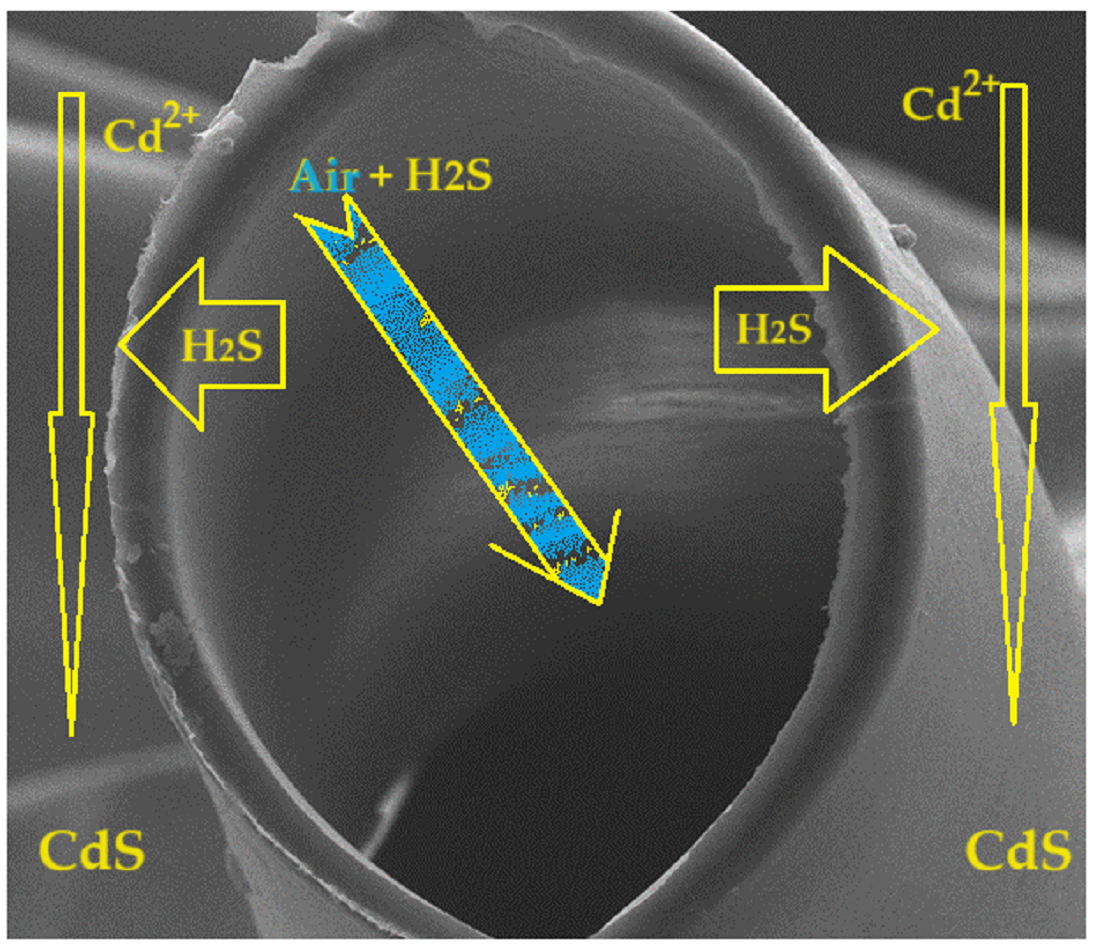
In the present paper, we propose a new way of retaining hydrogen sulfide from closed habitable premises by using membrane-based permeators and the hydrogen sulfide fixation reaction with cadmium ions in acidic aqueous solution (2):
Cd2+ + 2H2O+ H2S → CdS + H3O+
The acidic aqueous solution does not affect the formation of cadmium sulfide, which is stable in acid medium up to pH 2 [58].
The composite membranes proposed to be used in the permeation module (Figure 3) are obtained by impregnating polypropylene hollow fiber membrane support with cellulosic derivatives by the method illustrated in Figure 2.
The obtained composite membranes required morphological, structural characterization and the determination of process performances in the retention of hydrogen sulfide in the aqueous solution of cadmium ions.
Morphological characterization was carried out by scanning electron microscopy (SEM) and two-dimensional Fourier Transform InfraRed maps (2D FTIR maps).
The compositional characterization was carried out by analyzing the surface of the composite membranes, before and after the hydrogen sulfide retention process, by Energy Dispersive X-ray Spectroscopy (EDAX) and in the whole membrane by FTIR.
A special place of the study is thermal gravimetric analysis (TG) and differential calorimetric scanning (DSC), as it is proposed to use the membranes used in the process of making reflective road markings.
3.1. Morphologic and Structural Characterization
3.1.1. Morphologic Characterization
In order to determine the in-section and on the surface morphology of the composite membranes, one centimeter of the cellulosic derivative–polypropylene hollow fibers composite membrane is prepared, which is fractured and covered with a thin film (approx. 50 nm) of gold.
The diameter of sodium carboxymethyl–cellulose-polypropylene hollow fiber membrane (P1) (Figure 4a) is about 350 µm, with walls of approx. 20–30 µm, confirming the data obtained previously [57,58]. The surface of the composite membrane (Figures 4b, 4c and 4d) shows relatively evenly distributed pores with a diameter of about 1–2 µm. Figures 4d and 4e show the coverage of the polypropylene hollow fiber support with the cellulosic derivative, both on the surface of the fiber and inside the pores. The obtained data can also be observed for samples P2, P3 and P4 (see Figures S1, S2 and S3 in the Supplementary Material).
After use in the hydrogen sulfide separation process and capture as cadmium sulfide on the sodium carboxymethyl–cellulose–polypropylene hollow fiber membrane (P5), SEM is performed for the membrane section (Figure 5a) in which the layer of cadmium sulfide can be observed.
On the surface of the 'sodium carboxymethyl–cellulose–polypropylene hollow fiber' membrane (P5) the sizes of cadmium sulfide nanoparticles were presented (Figures 5b, 5c, 5d and 5e). At 160,000× resolution cadmium sulfide nanoparticles are measurable (Figure 5e).
3.1.2. Structural Characterization
For sodium carboxymethyl–cellulose-polypropylene hollow fiber membrane, the FTIR spectrum was obtained (Figure 6a), which allowed the choice of wave numbers for the creation of 2D maps. As can be seen in Figure 6b the spectra of the four composite membranes (P1, P2, P3 and P4) are relatively closed and the differences were illustrated in Figures S4, S5 and S6 (see the Supplementary Material).
Analyzing the spectra obtained for the four cellulosic derivatives–polypropylene hollow fiber composite membranes (Figure 6), the following wave numbers were chosen to create the 2D maps:
- 3386 cm−1 (–O–H stretching vibration from cellulose)
- 2950 cm−1 (C–H stretching vibration from PP and cellulose)
- 1639 cm−1 (C–O stretching vibration from cellulose)
- 1170 cm−1 (C–C stretching vibration from PP and cellulose)
Figure 7 shows the 2D maps for the composite membrane P1, and the supplementary material provides the information for the membranes P2, P3 and P4 (see Figures S7, S8 and S9 in the Supplementary Material).
The 2D maps show a varied distribution of the cellulosic derivative on the membrane surface: from 50% (in blue) in the center of the image center, to 90% (orange to red) in the sides (Figures> 7b, c, d and e). The way the colors are distributed suggest that the cellulosic derivative enters the membrane pores in the area where they are more abundant. It is worth noting that in all 2D maps the coloring of the areas is close. Similar information is provided by the 2D maps of the composite membranes P2, P3 and P4.
The structural characterization of the composite membranes (P1, P3 and P5) was completed with analysis through Energy Dispersive X-ray Spectroscopy EDAX (Figure 8).
The EDAX spectrum for the composite membrane sodium carboxymethyl–cellulose-polypropylene hollow fiber membrane (P1) (Figure 8a) highlights the composition in carbon, sodium and oxygen.
The EDAX spectrum for the methyl 2–hydroxyethyl–cellulose (MHEC)–polypropylene hollow fiber membrane (P5) composite membrane (Figure 8c) shows that carbon and oxygen elements are present.
The EDAX spectrum for the composite membrane sodium carboxymethyl–cellulose-polypropylene hollow fiber membrane, after retention of hydrogen sulfide as cadmium sulfide (P5), indicates the presence of sodium carbon, sulfur, and cadmium. The strong presence of cadmium and sulfur shows that the cadmium sulfide almost completely covers the composite membrane, which is also confirmed in Figure 5.
3.2. Thermal Characterization
The thermal analysis TG-DSC for the precursors was performed with a Netzsch STA 449C Jupiter apparatus. The cut samples (~4 mg) were placed in an open crucible made of alumina and heated with 10 from room temperature up to 650 °C, under the flow of 50 dried air. An empty alumina crucible was used as reference.
Samples P1–P4 (Figures 9a and 9b) have a similar thermal behavior due to presence of polypropylene fibers in their composition. The details necessary for the interpretation of the thermal diagrams are provided by the additional Figures S10, S11, S12 and S13 (see Supplementary Material), being presented next. The samples are losing around ~2.1–2.9% up to 200 °C due to solvent elimination and degradation of less stable terminal moieties. The endothermic effect recorded on the DSC curve in this temperature interval is caused by the melting of the polypropylene in the range 154–156 °C.
After 200 °C the degradation by fragmentation of polymer backbone and oxidation of the fragments is recorded. The overall DSC effect is exothermic, indicating the dominance of oxidation reactions over the fragmentation of polymer chain.
Up to 415 °C the samples are completely degraded, the exothermic effect from 380–390 °C being assigned to the burning of the residual carbonaceous mass.
The details of the interpretation of Figure 11 are depicted in the thermal diagrams in the supplementary material (Figures S14a and b) and presented below. After the process, the sodium carboxymethyl–cellulose–polypropylene hollow fiber membrane (P5) (Figure 11) being wet with the test solution, is losing the present solvent up to 200 °C. In this interval, the melting of the fibers is observable at 154.7 °C [68,69], with a melting enthalpy of 25.01 J/g.
The degradation of the polymer backbone starts after 200 °C by fragmentation and oxidation as previously reported in [57,70]. The oxidation process of the organic fragments is associated with the exothermic effect from 381.7 °C, while the burning of the residual carbonaceous mass is assigned to the exothermic peak from 482.0 °C.
A small exothermic effect at 683.2 °C is associated with a mass increase of 0.32% and can be attributed to the oxidation of CdS to CdSO4 and related species, as proven by CdS thermal analysis [71,72].
The P6 sample (CdS obtained in the hydrogen sulfide retention process on the membrane P1) (see Figure 12) exhibits a mass loss of 9.10% up to 175 °C, which can be assigned to residual humidity/crystallization water. The process is accompanied by a weak endothermic process on the DSC curve, with the minimum at 92.2 °C. The sample is losing 3.42% of its initial mass between 175–350 °C in an oxidative event, as indicated by the double exothermic peaks on the DSC curve, at 231.1 °C and 249.3 °C. This can imply simultaneous elimination of water and oxidation of CdS or obtaining of CdO by equation (3):
as reported before [71].
2CdS + 3O2 = 2CdO + 2SO2
The mass increase of 8.60% in the interval 350–740 °C indicates a further oxidation to CdSO4 or other species (Cd5S3O6; Cd(S2O7)) [71]. The oxidation process is accompanied by a strong and broad exothermic effect on the DSC curve, with maximum at 616.5 °C.
After 740 °C the compound starts to decompose, losing 12.07% of its mass up to 900 °C, literature proposing some reactions like (4) and (5) [71,72].
2CdS + 3O2 = 2CdO + 2SO2
CdS + CdSO4 = 2CdO + 2SO2
Thermal data show that sodium carboxymethyl–cellulose–polypropylene hollow fiber membrane (P5) after process can be used by heating it up to 200 °C, when both the polymer material and the cadmium sulfide retain their properties, but the polymer material dehydrates and melts, and nanometric cadmium sulfide is dehydrated.
The polymeric material containing nanometric cadmium sulfide could be used in the manufacturing process of reflective materials, including road ones.
3.3. Performance Processes for Hydrogen Sulfide Recuperative Separation
In this part of the work, the results of hydrogen sulfide retention from closed rooms, rooms in residential houses or hotels are presented.
The study parameters were chosen as follows:
- Volume of polluted air 5.0 m3;
- Surface of the composite membrane 0.1 m2;
-
Composite membranes cellulosic derivative–polypropylene hollow fiber:
- ∘
- sodium carboxymethyl–cellulose–polypropylene hollow fiber (P1)
- ∘
- cellulose acetate–polypropylene hollow fiber (P2)
- ∘
- methyl 2–hydroxyethyl–cellulose–polypropylene hollow fiber (P3)
- ∘
- 2–hydroxyethyl–cellulose–polypropylene hollow fiber (P4)
- Hydrogen sulfide concentrations of: 20 ppm, 40 ppm and 60 ppm;
- Hydrogen sulfide flow rates: 50 L/min, 100 L/min and 150 L/min;
- pH of cadmium nitrate receiving phase solution: 0, 2, 4 and 6.
3.3.1. Influence of the Nature of the Composite Membrane Nature on the Hydrogen Sulfide Pertraction Efficiency
Probably operating in the most unfavorable working conditions – concentration of hydrogen sulfide (60 ppm), flow-rate (150 L/min), maximum operating time of 85 minutes and pH = 6 – the sodium carboxymethyl–cellulose–polypropylene hollow fiber (P1), cellulose acetate–polypropylene hollow fiber (P2), methyl 2–hydroxyethyl–cellulose–polypropylene hollow fiber (P3) and 2–hydroxyethyl–cellulose–polypropylene hollow fiber (P4) membranes have the behavior indicated in Figure 13.
The pertraction efficiency over the entire time interval decreases in the order: sodium carboxymethyl–cellulose–polypropylene hollow fiber membrane (P1) >> cellulose acetate–polypropylene hollow fiber membrane (P2) > methyl 2–hydroxyethyl–cellulose–polypropylene hollow fiber membrane (P3) > 2–hydroxyethyl-cellulose–polypropylene hollow fiber membrane (P4).
Because the membrane sodium carboxymethyl–cellulose–polypropylene hollow fiber (P1) has the best pertraction efficiency, it will be chosen for the continuation of the study by varying the other parameters.
3.3.2. Influence of Hydrogen Sulfide Concentration on Hydrogen Sulfide Pertraction Efficiency
The concentration of hydrogen sulfide in the polluted air is the determining parameter for bringing the polluted air to bearable values and affecting health as little as possible.
In the conditions of some areas with mofettas or extinct volcanoes (e.g., Covasna-Harghita area, Romania) the concentration of hydrogen sulfide in homes near the generating sources is between 1.0 ppm and 50.0 ppm.
For the study of the pertraction variation (PE%), depending on the operating time using the composite membrane (P1) (Figure 14), three concentrations of hydrogen sulfide were chosen, which are at the limit of respiratory tract irritation (20 ppm, 40 ppm and 60 ppm). The membrane used was sodium carboxymethyl–cellulose-polypropylene hollow fiber (P1), the working flow was 150 L/min, the pH of the cadmium nitrate solution equal to 2 and the cadmium nitrate concentration 10−1 mol/L.
The obtained results show that the efficiency of the separation increases with the decrease in the concentration of hydrogen sulfide in the polluted air. Also, the results suggest operating in two or three permeation modules in series, or recirculating air through the module until cadmium is depleted from the cadmium nitrate receptor phase.
3.3.3. The Influence of the Flow Rate of the Air Polluted with Hydrogen Sulfide, on the Efficiency of Hydrogen Sulfide Pertraction
The flow rate of the hydrogen sulfide polluted air is conditioned by the volume of the premises subjected to the experiment and the time in which we want to bring the concentration of hydrogen sulfide to bearable olfactory limits.
In Figure 15, for a concentration of 60 ppm, pH = 2 in the receiving phase, the volume of air in the considered enclosure (premise) of 5.0 m3 and the composite membrane P1, it is observed that a small flow favors the efficiency of hydrogen sulfide pertraction the operating time reaches two hours for the flow rate of 50 L/min and over two hours at the flow rates of 100 L/min and 150 L/min.
The work flow is also conditioned by the need to pass through the pertraction module, at least once, the entire air volume of the considered room.
3.3.4. The Influence of the pH of the Cadmium Nitrate Solution on the Hydrogen Sulfide Pertraction Efficiency
The pH of the receiving phase of cadmium nitrate with a concentration of 0.1 mol/L influences the efficiency of hydrogen sulfide pertraction (Table 3). The conditions in which data were obtained are: composite membrane (P1) surface 0.1 m2, hydrogen sulfide concentration 20 ppm, work flow 50 L/min, operating time 2 hours, and the volume of treated polluted air 5 m3.
The results show that the optimal operating pH range is between 2 to 4. At low pH, cadmium sulfide does not reach the precipitation pH, and at high pH it precipitates simultaneously with cadmium sulfide and cadmium carbonate resulted from cadmium ions and the carbon dioxide from polluted air. A further increase in pH is undesirable because the hydroxyl ions that precipitate the cadmium hydroxide will enter the competition.
Following the pertraction experiments of hydrogen sulfide from the polluted air, through sodium carboxymethyl–cellulose–polypropylene hollow fiber membrane (P1), with a cadmium nitrate receptor phase at pH 2, working flow rate of 50 L/min, at a working time of 2 hours, the membrane covered with cadmium sulfide (P5) (Figure 16) is obtained, suitable for thermal treatment (melting) and obtaining reflective material.
4. Conclusions
Treating polluted air with hydrogen sulfide is an important problem for the residential premises in areas with mofettas or extinct volcanoes.
This paper presents the results of hydrogen sulfide removal from an enclosure with a defined volume using cellulosic derivative-polypropylene hollow fiber composite membranes. All membranes obtained were characterized by SEM, EDAX, FTIR, 2D FTIR maps and thermal analysis (TG, DSC). Among the four prepared membranes: sodium carboxymethyl–cellulose–polypropylene hollow fiber (P1), cellulose acetate–polypropylene hollow fiber (P2), methyl 2–hydroxyethyl–cellulose–polypropylene hollow fiber (P3), and 2–hydroxyethyl–cellulose–polypropylene hollow fiber (P4) the best results of hydrogen sulfide pertraction and capture in a receiving phase of cadmium nitrate solution were obtained with the composite membrane P1.
The optimal operating conditions are: flow rate of 50 L/min of air polluted with 20 ppm hydrogen sulfide, pH between 2 and 4 for the receiving phase of cadmium nitrate of concentration 0.1 mol/L.
The membrane covered with cadmium sulfide is recommended for heat treatment (melting) and obtaining reflective material for road markings.
Supplementary Materials
The following supporting information can be downloaded at: Preprints.org, Figure S1: Scanning electron microscopy for cellulose acetate–polypropylene hollow fiber membrane (P2); Figure S2: Scanning electron microscopy for methyl 2–hydroxyethyl–cellulose (MHEC)–polypropylene hollow fiber membrane (P2); Figure S3: Scanning electron microscopy for 2–hydroxyethyl–cellulose (HEC)–polypropylene hollow fiber membrane (P2); Figure S4: Fourier Transform Infra-Red (FTIR) spectra for P2 composite membrane; Figure S5: Fourier Transform Infra-Red (FTIR) spectra for P3 composite membrane; Figure S6: Fourier Transform Infra-Red (FTIR) spectra for P4 composite membrane; Figure S7: FTIR 2D maps for cellulose acetate–polypropylene hollow fiber membrane; Figure S8: FTIR 2D maps for methyl 2–hydroxyethyl–cellulose –polypropylene hollow fiber membrane; Figure S9: FTIR 2D maps for 2–hydroxyethyl–cellulose –polypropylene hollow fiber membrane; Figure S10: Detail of thermal diagrams for P1; Figure S11: Detail of thermal diagrams for P2; Figure S12: Detail of thermal diagrams for P3; Figure S13: Detail of thermal diagrams for P4; Figure S14: Zoom-in detail for Figure 11, in case of P5; Figure S15: Detail of thermal diagrams for P5.
Author Contributions
Conceptualization, P.C.A., A.P., G.N., and V.-A.G.; methodology, A.C.N., A.R.G. and L.M.; validation, L.M., S.-K.T., and A.R.G.; formal analysis, A.C.N., A.R.G., and L.M.; investigation, L.M., P.C.A., G.T.M., G.N., V.-A.G.; A.C.N., A.R.G. and A.P.; resources, G.N., S.-K.T., and, P.C.A.; data curation, L.M., A.C.N., A.R.G., V.-A.G. writing—original draft preparation, P.C.A., A.P., G.N., A.C.N., and V.-A.G.; writing—review and editing, P.C.A., A.P., G.N., and V.-A.G. All authors have read and agreed to the published version of the manuscript.
Funding
This research received no external funding.
Institutional Review Board Statement
Not applicable.
Informed Consent Statement
Not applicable.
Data Availability Statement
The original contributions presented in the study are included in the article/supplementary material, further inquiries can be directed to the corresponding authors.
Acknowledgments
The authors are grateful to the Romanian Government for providing access to the research infrastructure of the National Center for Micro and Nanomaterials through the National Program titled “Installations and Strategic Objectives of National Interest”. The authors gratefully acknowledge the valuable help and friendly assistance of Eng. Roxana Truşcă for performing the microscopy analysis.
Conflicts of Interest
The authors declare no conflicts of interest.
References
- Zaorska, E.; Tomasova, L.; Koszelewski, D.; Ostaszewski, R.; Ufnal, M. Hydrogen Sulfide in Pharmacotherapy, Beyond the Hydrogen Sulfide-Donors. Biomolecules 2020, 10, 323. [Google Scholar] [CrossRef] [PubMed]
- Andrés, C.M.C.; Pérez de la Lastra, J.M.; Andrés Juan, C.; Plou, F.J.; Pérez-Lebeña, E. Chemistry of Hydrogen Sulfide—Pathological and Physiological Functions in Mammalian Cells. Cells 2023, 12, 2684. [Google Scholar] [CrossRef] [PubMed]
- Casertano, M.; Esposito, E.; Bello, I.; Indolfi, C.; Putra, M.Y.; Di Cesare Mannelli, L.; Ghelardini, C.; Menna, M.; Sorrentino, R.; Cirino, G.; et al. Searching for Novel Sources of Hydrogen Sulfide Donors: Chemical Profiling of Polycarpa aurata Extract and Evaluation of the Anti-Inflammatory Effects. Mar. Drugs 2023, 21, 641. [Google Scholar] [CrossRef] [PubMed]
- Jánosi, C.; Karátson, D.; Wanek, F., History of Research: Geoscientific Exploration of the Ciomadul Hills. In Ciomadul (Csomád), The Youngest Volcano in the Carpathians: Volcanism, Palaeoenvironment, Human Impact 2022, pp. 3-28. Cham: Springer International Publishing. [CrossRef]
- Gorini, F.; Bustaffa, E.; Chatzianagnostou, K.; Bianchi, F; Vassalle, C. Hydrogen sulfide and cardiovascular disease: Doubts, clues, and interpretation difficulties from studies in geothermal areas. Science of The Total Environment 2020, 743, p.140818. [CrossRef]
- Diliberto, I.S.; Cangemi, M.; Gagliano, A.L.; Inguaggiato, S.; Jacome Paz, M.P.; Madonia, P.; Mazot, A.; Pedone, M.; Pisciotta, A. Volcanic Gas Hazard Assessment in the Baia di Levante Area (Vulcano Island, Italy) Inferred by Geochemical Investigation of Passive Fluid Degassing. Geosciences. 2021, 11(11), 478. [Google Scholar] [CrossRef]
- Aventaggiato, L.; Colucci, A. P.; Strisciullo, G.; Favalli, F.; Gagliano-Candela, R. Lethal Hydrogen Sulfide poisoning in open space: An atypical case of asphyxiation of two workers. Forensic Science International, 2020, 308, 110122. [Google Scholar] [CrossRef]
- Fernandes, D.J.; Ferreira, A.F.; Fernandes, E.C. Biogas and Biomethane Production Potential via Anaerobic Digestion of Manure: A Case Study of Portugal. Renew. Sustain. Energy Rev. 2023, 188, 113846. [Google Scholar] [CrossRef]
- Park, J.-R.; Jang, Y.-H.; Kim, E.-G.; Lee, G.-S.; Kim, K.-M. Nitrogen Fertilization Causes Changes in Agricultural Characteristics and Gas Emissions in Rice Field. Sustainability 2023, 15, 3336. [Google Scholar] [CrossRef]
- Kailasa, S.K.; Koduru, J.R.; Vikrant, K.; Tsang, Y.F.; Singhal, R.K.; Hussain, C.M.; Kim, K.H. Recent progress on solution and materials chemistry for the removal of hydrogen sulfide from various gas plants. Journal of Molecular Liquids, 2020, 297, p.111886. [Google Scholar] [CrossRef]
- Shi, L.; Yang, Q.; Xu, Z.; Yang, C. Technologies for in-situ H2S control in wastewater treatment plants: A review. Journal of Water Process Engineering, 2024, 65, p.105716. [Google Scholar] [CrossRef]
- Waheed, A.; Aljundi, I.H.; Baig, U. Recovery of Dissolved Hydrogen Sulfide from Various Wastewater Streams Using Membranes and Other Relevant Techniques: A Review. Membranes 2023, 13, 646. [Google Scholar] [CrossRef]
- Ziganshina, E.E.; Belostotskiy, D.E.; Bulynina, S.S.; Ziganshin, A.M. Influence of Granular Activated Carbon on Anaerobic Co-Digestion of Sugar Beet Pulp and Distillers Grains with Solubles. Processes 2020, 8, 1226. [Google Scholar] [CrossRef]
- Yildiz, Y. A. New Approach to Hydrogen Sulfide Removal. J. Chem. Soc. Pak. 2022, 44, 17. [Google Scholar]
- Hruška, M.; Variny, M.; Haydary, J.; Janošovský, J. Sulfur Recovery from Syngas in Pulp Mills with Integrated Black Liquor Gasification. Forests 2020, 11, 1173. [Google Scholar] [CrossRef]
- Liu, Z.; Wang, Y.; Zhai, Y.; Qiao, Y.; Zheng, C.; Wang, D.; Shi, X.; Lu, H.; Liu, C. Corrosion behavior of low alloy steel used for new pipeline exposed to H2S-saturated solution. International Journal of Hydrogen Energy, 2022, 47(77), pp.33000–33013. [Google Scholar] [CrossRef]
- Vakili, M.; Koutník, P.; Kohout, J. Addressing Hydrogen Sulfide Corrosion in Oil and Gas Industries: A Sustainable Perspective. Sustainability 2024, 16, 1661. [Google Scholar] [CrossRef]
- Aroca, A.; Gotor, C.; Bassham, D.C.; Romero, L.C. Hydrogen Sulfide: From a Toxic Molecule to a Key Molecule of Cell Life. Antioxidants 2020, 9, 621. [Google Scholar] [CrossRef] [PubMed]
- Khattak, S.; Rauf, M.A.; Khan, N.H.; Zhang, Q.-Q.; Chen, H.-J.; Muhammad, P.; Ansari, M.A.; Alomary, M.N.; Jahangir, M.; Zhang, C.-Y.; et al. Hydrogen Sulfide Biology and Its Role in Cancer. Molecules 2022, 27, 3389. [Google Scholar] [CrossRef]
- Nagahara, N.; Wróbel, M. H2S, Polysulfides, and Enzymes: Physiological and Pathological Aspects. Biomolecules 2020, 10, 640. [Google Scholar] [CrossRef] [PubMed]
- Robinson, E.; Robbins, R. C. Gaseous sulfur pollutants from urban and natural sources. J. Air Pollut. Control Assoc. 1970, 20, 233–235. [Google Scholar] [CrossRef]
- Beck, J. F.; Cormier, F.; Donini, J. C. The combined toxicity of ethanol and hydrogen sulfide. Toxicol. Lett., 1979, 3, 311–313. [Google Scholar] [CrossRef]
- Pudi, A; Rezaei, M.; Signorini, V.; Andersson, M.P.; Baschetti, M.G.; Mansouri, S.S. Hydrogen sulfide capture and removal technologies: A comprehensive review of recent developments and emerging trends. Separation and Purification Technology, 2022, 298, p.121448. [CrossRef]
- Georgiadis, A.G.; Charisiou, N.D.; Goula, M.A. Removal of Hydrogen Sulfide From Various Industrial Gases: A Review of The Most Promising Adsorbing Materials. Catalysts 2020, 10, 521. [Google Scholar] [CrossRef]
- Chan, Y.H.; Lock, S.S.M.; Wong, M.K.; Yiin, C.L.; Loy, A.C.M.; Cheah, K.W.; Chai, S.Y.W.; Li, C.; How, B.S.; Chin, B.L.F.; Chan, Z.P. A state-of-the-art review on capture and separation of hazardous hydrogen sulfide (H2S): Recent advances, challenges and outlook. Environmental Pollution, 2022, 314, p.120219. [Google Scholar] [CrossRef] [PubMed]
- Ahmad, W.; Sethupathi, S.; Kanadasan, G.; Lau, L.C.; Kanthasamy, R. A review on the removal of hydrogen sulfide from biogas by adsorption using sorbents derived from waste. Reviews in Chemical Engineering, 2021, 37(3), pp.407–431. [Google Scholar] [CrossRef]
- Tilahun, E.; Sahinkaya, E.; Çalli, B. A hybrid membrane gas absorption and bio-oxidation process for the removal of hydrogen sulfide from biogas. Int. Biodeterior. Biodegrad. 2018, 127, 69–76. [Google Scholar] [CrossRef]
- Kang, J.; Song, J.; Ji, H.; Yun, S.; Kim, W.; Yoo, S. Effects of H2S Loading Rate on the Performance of Reactive Absorption with Electrochemical Oxidation. Appl. Sci. 2021, 11, 4867. [Google Scholar] [CrossRef]
- Wang, Y.; Wang, Z.; Pan, J.; Liu, Y. Removal of gaseous hydrogen sulfide using Fenton reagent in a spraying reactor. Fuel 2019, 239, 70–75. [Google Scholar] [CrossRef]
- Yang, C.; Wang, Y.; Fan, H.; de Falco, G.; Yang, S.; Shangguan, J.; Bandosz, T.J. Bifunctional ZnO-MgO/activated carbon adsorbents boost H2S room temperature adsorption and catalytic oxidation. Appl. Catal. B Environ. 2020, 266, 118674. [Google Scholar] [CrossRef]
- Barbusiński, K.; Parzentna-Gabor, A.; Kasperczyk, D. Removal of Odors (Mainly H2S and NH3) Using Biological Treatment Methods. Clean Technol. 2021, 3, pp.138–155. [Google Scholar] [CrossRef]
- Xie, L.; Zhu, J.; Hu, J.; Jiang, C. Study of the mass transfer–biodegradation kinetics in a pilot-scale biotrickling filter for the removal of H2S. Industrial & Engineering Chemistry Research, 2020, 59(17), pp.8383–8392. [Google Scholar] [CrossRef]
- Manyi-Loh, C.E.; Lues, R. Anaerobic Digestion of Lignocellulosic Biomass: Substrate Characteristics (Challenge) and Innovation. Fermentation 2023, 9, 755. [Google Scholar] [CrossRef]
- Secco, C.; Fuziki, M.E.K.; Tusset, A.M.; Lenzi, G.G. Reactive Processes for H2S Removal. Energies 2023, 16, 1759. [Google Scholar] [CrossRef]
- Alguacil, F.J. Recent Advances in H2S Removal from Gas Streams. Appl. Sci. 2023, 13, 3217. [Google Scholar] [CrossRef]
- Imtiaz, A.; Othman, M.H.D.; Jilani, A.; Khan, I.U.; Kamaludin, R.; Iqbal, J.; Al-Sehemi, A.G. Challenges, Opportunities and Future Directions of Membrane Technology for Natural Gas Purification: A Critical Review. Membranes 2022, 12, 646. [Google Scholar] [CrossRef] [PubMed]
- Rao, S.; Prasad, B.; Han, Y.; Ho, W.S.W. Polymeric Membranes for H2S and CO2 Removal from Natural Gas for Hydrogen Production: A Review. Energies 2023, 16, 5713. [Google Scholar] [CrossRef]
- Ma, Y.; Guo, H.; Selyanchyn, R.; Wang, B.; Deng, L.; Dai, Z.; Jiang, X. Hydrogen sulfide removal from natural gas using membrane technology: A review. Journal of materials Chemistry A, 2021, 9(36), pp.20211–20240. [Google Scholar] [CrossRef]
- Peng, L.; Shi, M.; Zhang, X.; Xiong, W.; Hu, X.; Tu, Z.; Wu, Y. Facilitated transport separation of CO2 and H2S by supported liquid membrane based on task-specific protic ionic liquids. Green Chemical Engineering, 2022, 3(3), pp.259–266. [Google Scholar] [CrossRef]
- Yahaya, G.O.; Hayek, A.; Alsamah, A.; Shalabi, Y.A.; Sultan, M.M.B.; Alhajry, R.H. Copolyimide membranes with improved H2S/CH4 selectivity for high-pressure sour mixed-gas separation. Separation and Purification Technology, 2021, 272, p.118897. [Google Scholar] [CrossRef]
- Tomczak, W.; Gryta, M.; Daniluk, M.; Żak, S. Biogas Upgrading Using a Single-Membrane System: A Review. Membranes 2024, 14, 80. [Google Scholar] [CrossRef]
- Nemestóthy, N.; Bakonyi, P.; Lajtai-Szabó, P.; Bélafi-Bakó, K. The Impact of Various Natural Gas Contaminant Exposures on CO2/CH4 Separation by a Polyimide Membrane. Membranes 2020, 10, 324. [Google Scholar] [CrossRef]
- Morisato, A.; Mahley, E. Hydrogen sulfide permeation and hydrocarbon separation properties in cellulose triacetate hollow fiber membrane for high hydrogen sulfide contained natural gas sweetening applications. J. Membr. Sci. 2023, 681, p.121734. [Google Scholar] [CrossRef]
- Samimi, A.; Zarinabadi, S.; Bozorgian, A.; Amosoltani, A.; Esfahani, M.S.T.; Kavousi, M.K. Advances of Membrane Technology in Acid Gas Removal in Industries. Prog. Chem. Biochem. Res. 2020, 3, 46–54. [Google Scholar] [CrossRef]
- Agboola, O.; Fayomi, O.S.I.; Ayodeji, A.; Ayeni, A.O.; Alagbe, E.E.; Sanni, S.E.; Okoro, E.E.; Moropeng, L.; Sadiku, R.; Kupolati, K.W.; et al. A Review on Polymer Nanocomposites and Their Effective Applications in Membranes and Adsorbents for Water Treatment and Gas Separation. Membranes 2021, 11, 139. [Google Scholar] [CrossRef] [PubMed]
- Matson, S.L. , Herrick, C.S. and Ward, W.J., Progress on the selective removal of H2S from gasified coal using an immobilized liquid membrane. Industrial & Engineering Chemistry Process Design and Development 1977, 16(3), pp.370–374. [Google Scholar] [CrossRef]
- Akhmetshina, A.I.; Yanbikov, N.R.; Atlaskin, A.A.; Trubyanov, M.M.; Mechergui, A.; Otvagina, K.V.; Razov, E.N.; Mochalova, A.E.; Vorotyntsev, I.V. Acidic Gases Separation from Gas Mixtures on the Supported Ionic Liquid Membranes Providing the Facilitated and Solution-Diffusion Transport Mechanisms. Membranes 2019, 9, 9. [Google Scholar] [CrossRef] [PubMed]
- Ramos, V.C.; Han, W.; Zhang, X.; Zhang, S.; Yeung, K.L. Supported ionic liquids for air purification. Curr. Opin. Green Sustain. Chem. 2020, 25, 100391. [Google Scholar] [CrossRef]
- Othman, N.H.; Alias, N.H.; Fuzil, N.S.; Marpani, F.; Shahruddin, M.Z.; Chew, C.M.; David Ng, K.M.; Lau, W.J.; Ismail, A.F. A Review on the Use of Membrane Technology Systems in Developing Countries. Membranes 2022, 12, 30. [Google Scholar] [CrossRef] [PubMed]
- Helmi, A.; Gallucci, F. Latest Developments in Membrane (Bio)Reactors. Processes 2020, 8, 1239. [Google Scholar] [CrossRef]
- Iulianelli, A.; Drioli, E. Membrane engineering: Latest advancements in gas separation and pre-treatment processes, petrochemical industry and refinery, and future perspectives in emerging applications. Fuel Process. Technol. 2020, 206, 106464. [Google Scholar] [CrossRef]
- Bazhenov, S.D.; Bildyukevich, A.V.; Volkov, A.V. Gas-Liquid Hollow Fiber Membrane Contactors for Different Applications. Fibers 2018, 6, 76. [Google Scholar] [CrossRef]
- Escorihuela, J.; Olvera-Mancilla, J.; Alexandrova, L.; del Castillo, L.F.; Compañ, V. Recent Progress in the Development of Composite Membranes Based on Polybenzimidazole for High Temperature Proton Exchange Membrane (PEM) Fuel Cell Applications. Polymers 2020, 12, 1861. [Google Scholar] [CrossRef] [PubMed]
- Khraisheh, M.; Elhenawy, S.; AlMomani, F.; Al-Ghouti, M.; Hassan, M.K.; Hameed, B.H. Recent Progress on Nanomaterial-Based Membranes for Water Treatment. Membranes 2021, 11, 995. [Google Scholar] [CrossRef] [PubMed]
- Batista, M.; Pinto, M.L.; Antunes, F.; Pires, J.; Carvalho, S. Chitosan Biocomposites for the Adsorption and Release of H2S. Materials 2021, 14, 6701. [Google Scholar] [CrossRef]
- Ahmed, S.; Arshad, T.; Zada, A.; Afzal, A.; Khan, M.; Hussain, A.; Hassan, M.; Ali, M.; Xu, S. Preparation and Characterization of a Novel Sulfonated Titanium Oxide Incorporated Chitosan Nanocomposite Membranes for Fuel Cell Application. Membranes 2021, 11, 450. [Google Scholar] [CrossRef]
- Nechifor AC, Cotorcea S, Bungău C, Albu PC, Pașcu D, Oprea O, Grosu AR, Pîrțac A, Nechifor G. Removing of the Sulfur Compounds by Impregnated Polypropylene Fibers with Silver Nanoparticles-Cellulose Derivatives for Air Odor Correction. Membranes. 2021; 11(4):256. [CrossRef]
- Pașcu, D.; Nechifor, A.C.; Grosu, V.-A.; Oprea, O.C.; Tanczos, S.-K.; Man, G.T.; Dumitru, F.; Grosu, A.R.; Nechifor, G. Hydrogen Sulphide Sequestration with Metallic Ions in Acidic Media Based on Chitosan/sEPDM/Polypropylene Composites Hollow Fiber Membranes System. Membranes 2023, 13, 350. [Google Scholar] [CrossRef] [PubMed]
- Nechifor, A.C.; Pîrțac, A.; Albu, P.C.; Grosu, A.R.; Dumitru, F.; Dimulescu, I.A.; Oprea, O.; Pașcu, D.; Nechifor, G.; Bungău, S.G. Recuperative Amino Acids Separation through Cellulose Derivative Membranes with Microporous Polypropylene Fiber Matrix. Membranes 2021, 11, 429. [Google Scholar] [CrossRef]
- Ghimpusan, M.; Nechifor, G.; Din, I.S.; Nechifor, A.C.; Passeri, P. Application of hollow fibre membrane bioreactor instead of granular activated carbon filtration for treatment of wastewater from car dismantler activity. Mat. Plast. 2016, 53, pp.578–584. [Google Scholar]
- Urducea, C.B.; Nechifor, A.C.; Dimulescu, I.A.; Oprea, O.; Nechifor, G.; Totu, E.E.; Isildak, I.; Albu, P.C.; Bungău, S.G. Control of Nanostructured Polysulfone Membrane Preparation by Phase Inversion Method. Nanomaterials 2020, 10, 2349. [Google Scholar] [CrossRef] [PubMed]
- Pîrțac, A.; Nechifor, A.C.; Tanczos, S.-K.; Oprea, O.C.; Grosu, A.R.; Matei, C.; Grosu, V.-A.; Vasile, B.Ș.; Albu, P.C.; Nechifor, G. Emulsion Liquid Membranes Based on Os–NP/n–Decanol or n–Dodecanol Nanodispersions for p–Nitrophenol Reduction. Molecules 2024, 29, 1842. [Google Scholar] [CrossRef]
- Paun, G.; Neagu, E.; Parvulescu, V.; Anastasescu, M.; Petrescu, S.; Albu, C.; Nechifor, G.; Radu, G.L. New Hybrid Nanofiltration Membranes with Enhanced Flux and Separation Performances Based on Polyphenylene Ether-Ether-Sulfone/Polyacrylonitrile/SBA-15. Membranes 2022, 12, 689. [Google Scholar] [CrossRef]
- Man, G.T.; Albu, P.C.; Nechifor, A.C.; Grosu, A.R.; Popescu, D.I.; Grosu, V.-A.; Marinescu, V.E.; Nechifor, G. Simultaneously Recovery of Thorium and Tungsten through Hybrid Electrolysis–Nanofiltration Processes. Toxics 2024, 12, 103. [Google Scholar] [CrossRef]
- Hancock, J.T. Hydrogen sulfide and environmental stresses. Environ. Exp. Bot. 2019, 161, 50–56. [Google Scholar] [CrossRef]
- Dimulescu, I.A.; Nechifor, A.C.; Bǎrdacǎ, C.; Oprea, O.; Paşcu, D.; Totu, E.E.; Albu, P.C.; Nechifor, G.; Bungău, S.G. Accessible Silver-Iron Oxide Nanoparticles as a Nanomaterial for Supported Liquid Membranes. Nanomaterials 2021, 11, 1204. [Google Scholar] [CrossRef] [PubMed]
- Razvan, A.; Man, G.T.; Dumitru, F.; Pandele, M.; Trusca, R.; Motelica, L.; Oprea, O.; Nechifor, G. Nanocomposite membranes prepared from cellulose acetate or polysulfone with Ag0 nanoparticles and nitron reagent for nitrate ion removal. Desalination and Water Treatment, 2024, 318, p.100400. [Google Scholar] [CrossRef]
- Nechifor, A.C.; Goran, A.; Grosu, V.-A.; Bungău, C.; Albu, P.C.; Grosu, A.R.; Oprea, O.; Păncescu, F.M.; Nechifor, G. Improving the Performance of Composite Hollow Fiber Membranes with Magnetic Field Generated Convection Application on pH Correction. Membranes 2021, 11, 445. [Google Scholar] [CrossRef] [PubMed]
- Nechifor, A.C.; Pîrțac, A.; Albu, P.C.; Grosu, A.R.; Dumitru, F.; Dimulescu, I.A.; Oprea, O.; Pașcu, D.; Nechifor, G.; Bungău, S.G. Recuperative Amino Acids Separation through Cellulose Derivative Membranes with Microporous Polypropylene Fiber Matrix. Membranes 2021, 11, 429. [Google Scholar] [CrossRef] [PubMed]
- Nechifor, G.; Păncescu, F.M.; Grosu, A.R.; Albu, P.C.; Oprea, O.; Tanczos, S.-K.; Bungău, C.; Grosu, V.-A.; Pîrțac, A.; Nechifor, A.C. Osmium Nanoparticles-Polypropylene Hollow Fiber Membranes Applied in Redox Processes. Nanomaterials 2021, 11, 2526. [Google Scholar] [CrossRef]
- Anita Trenczek-Zajac, A. Thermally oxidized CdS as a photoactive material, New J. Chem. 2019, 43, 8892–8902. [Google Scholar] [CrossRef]
- Dantas, G.V.J. , de Moraes, N.P., Bacani, R. and Rodrigues, L.A., Facile synthesis of cadmium sulfide and the effect of thermal annealing in N2-rich atmosphere on its structural, morphological, chemical, and optical properties. Materials Chemistry and Physics, 2022, 277, p.125492. [Google Scholar] [CrossRef]
Figure 1.
Dependence of hydrogen sulfide action on humans, according to its concentration in the air.
Figure 1.
Dependence of hydrogen sulfide action on humans, according to its concentration in the air.
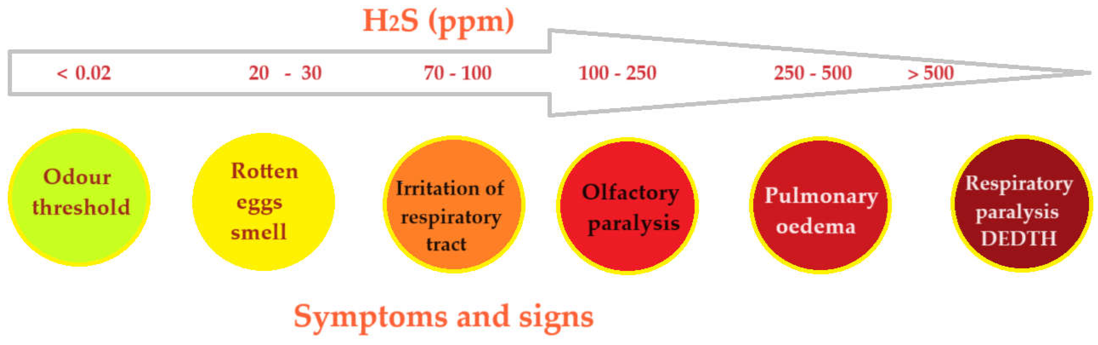
Figure 2.
Schematic presentation of the installation for the preparation of composite membrane: MM – membrane module; DMF – dimethyl formamide; RP – recirculation pumps. [64].
Figure 2.
Schematic presentation of the installation for the preparation of composite membrane: MM – membrane module; DMF – dimethyl formamide; RP – recirculation pumps. [64].
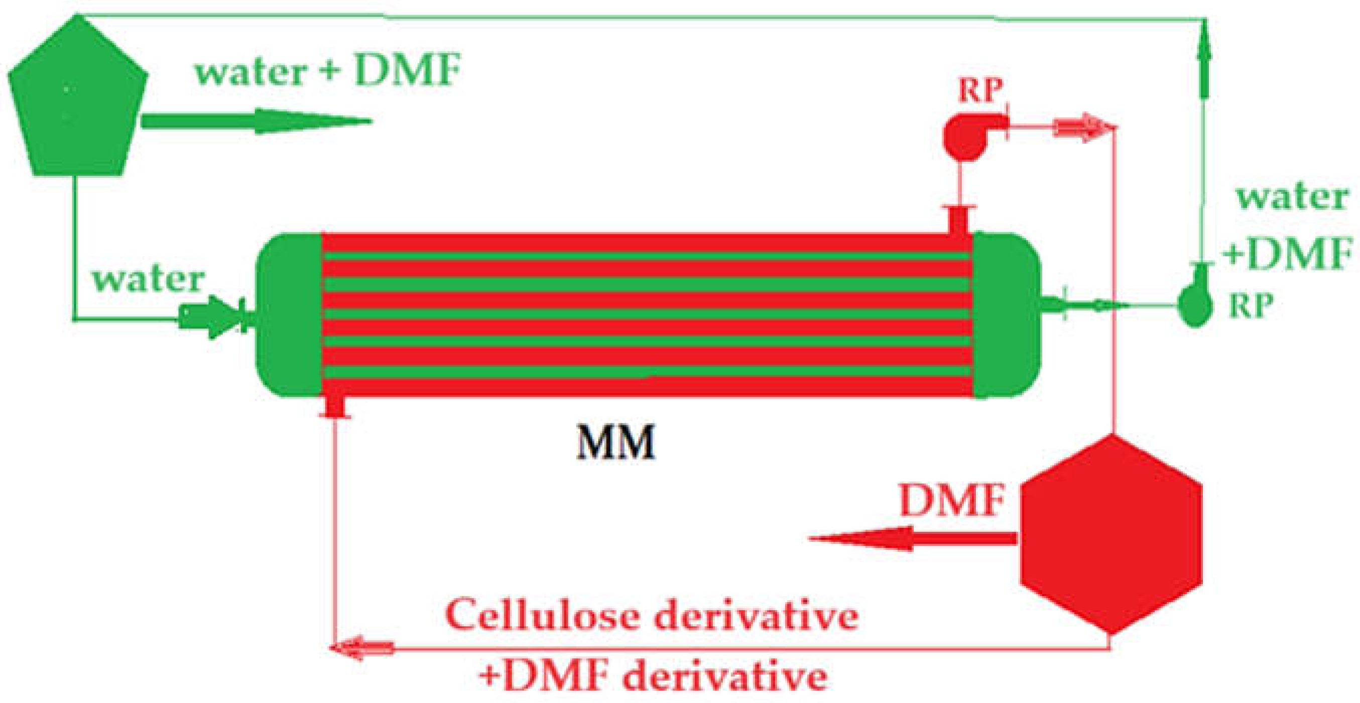
Figure 3.
Schematic presentation of the laboratory installation for hydrogen sulfide sequestration from a gaseous mixture: 1 – membrane contactor; 2 – composite hollow fiber membranes; 3 – pump for metal ions acidic solutions; 4 and 5 – gas-liquid separator; 6 – homogenization; 7 – quiet room; 8 – sodium hydroxide hatch. [58].
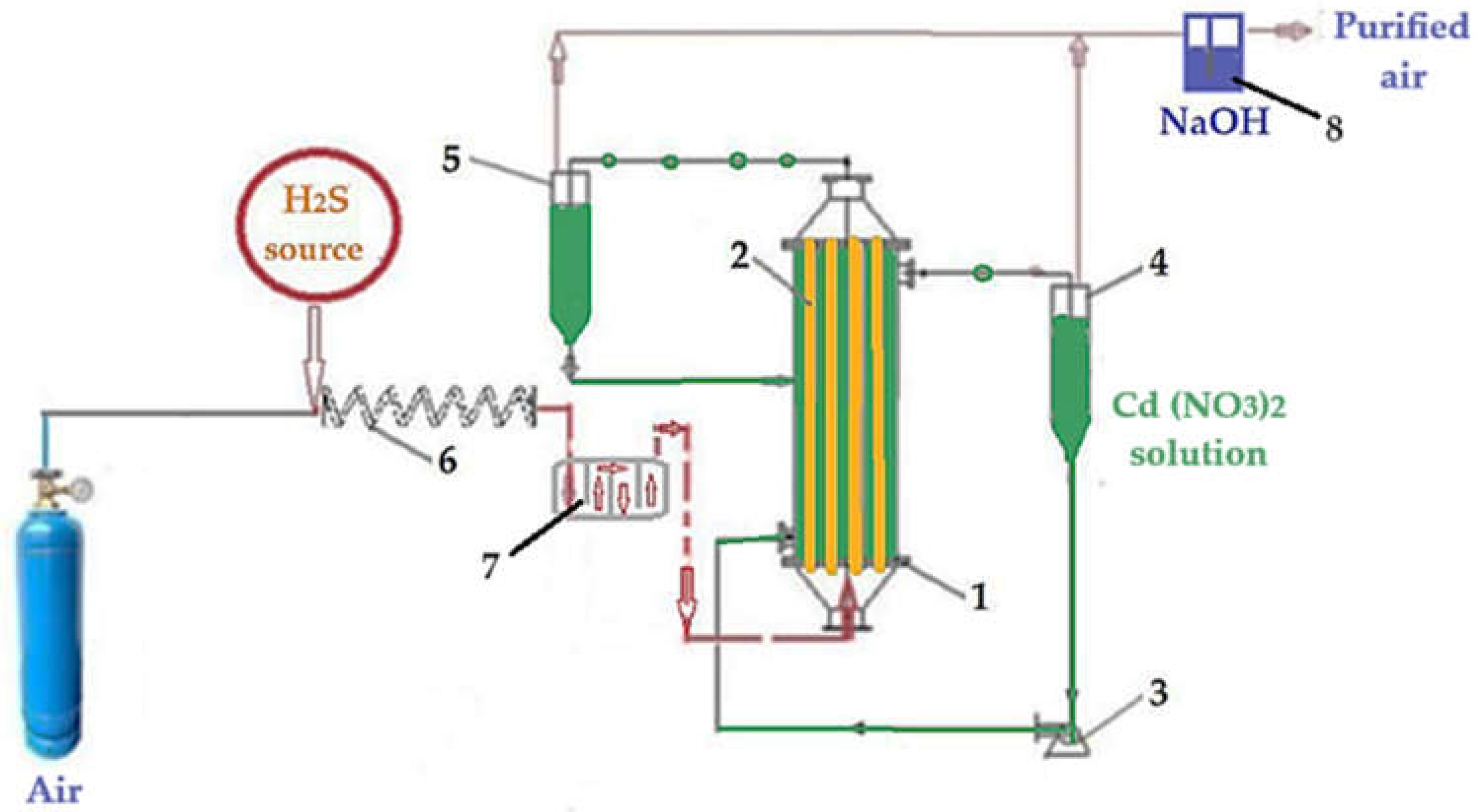
Figure 4.
Scanning electron microscopy for sodium carboxymethyl–cellulose–polypropylene hollow fiber membrane (P1): (a) composite membrane section; (b) membrane surface at 20,000× magnification; (c) membrane surface at 40,000× magnification; (d) membrane surface at 80,000× magnification; and (e) membrane surface at 160,000× magnification.
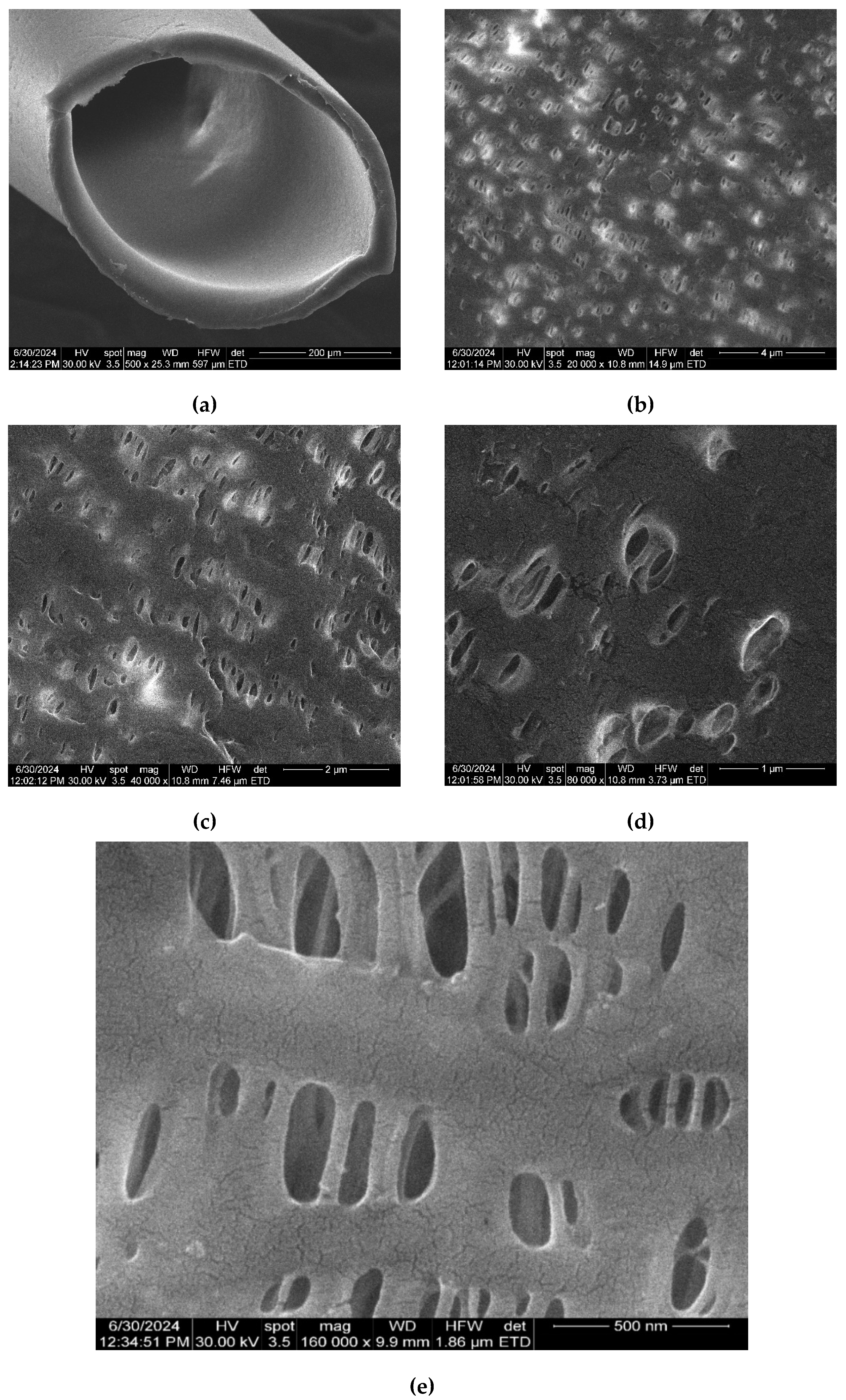
Figure 5.
Scanning electron microscopy for sodium carboxymethyl–cellulose–polypropylene hollow fiber membrane after using hydrogen sulfide in the separation process and capturing as cadmium sulfide (P5): (a) composite membrane section; (b) membrane surface at 20,000× magnification; (c) membrane surface at 40,000× magnification; (d) membrane surface at 80,000× magnification; and (e) membrane surface at 160,000× magnification.
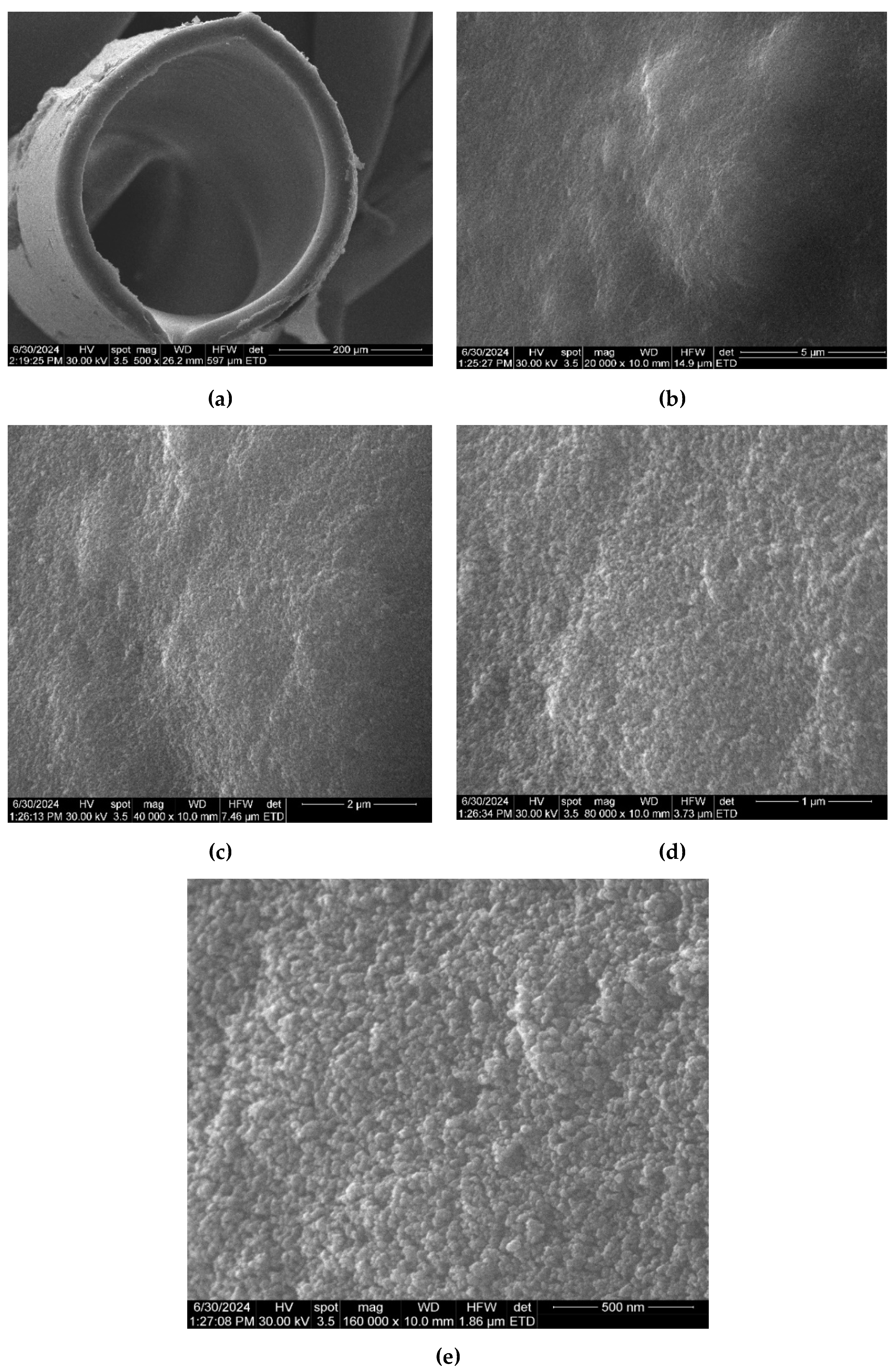
Figure 6.
Fourier Transform Infra-Red (FTIR) spectra for: (a) composite membrane P1; and (b) the four samples P1, P2, P3 and P4.
Figure 6.
Fourier Transform Infra-Red (FTIR) spectra for: (a) composite membrane P1; and (b) the four samples P1, P2, P3 and P4.
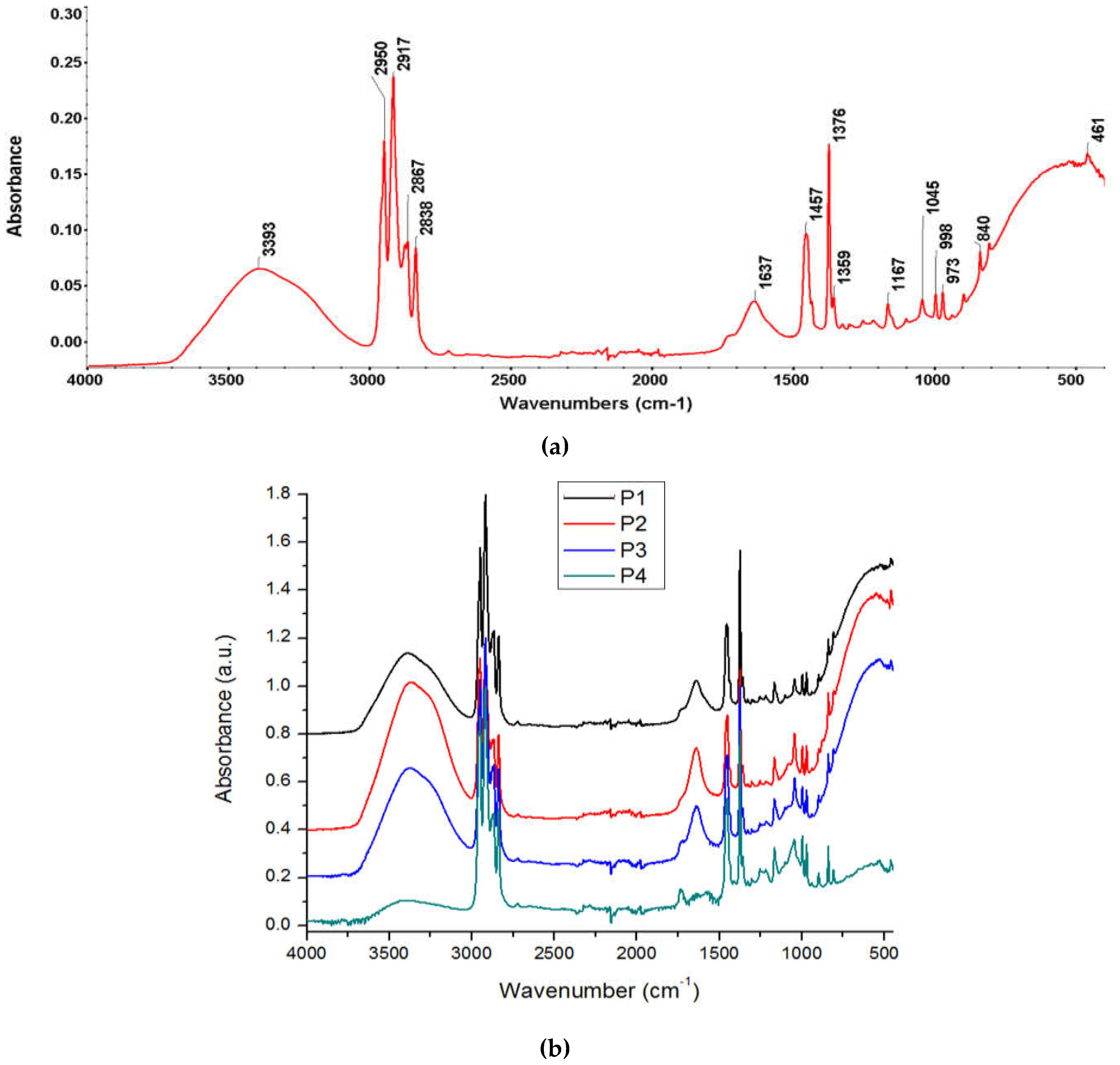
Figure 7.
FTIR 2D maps for sodium carboxymethyl–cellulose–polypropylene hollow fiber membrane: (a) the video image; (b) 2D image at wavenumber 3386 cm−1; (c) 2D image at wavenumber 2950 cm−1; (d) 2D image at wavenumber 1639 cm−1; and (e) 2D image at wavenumber 1170 cm−1; (f) color scale.
Figure 7.
FTIR 2D maps for sodium carboxymethyl–cellulose–polypropylene hollow fiber membrane: (a) the video image; (b) 2D image at wavenumber 3386 cm−1; (c) 2D image at wavenumber 2950 cm−1; (d) 2D image at wavenumber 1639 cm−1; and (e) 2D image at wavenumber 1170 cm−1; (f) color scale.
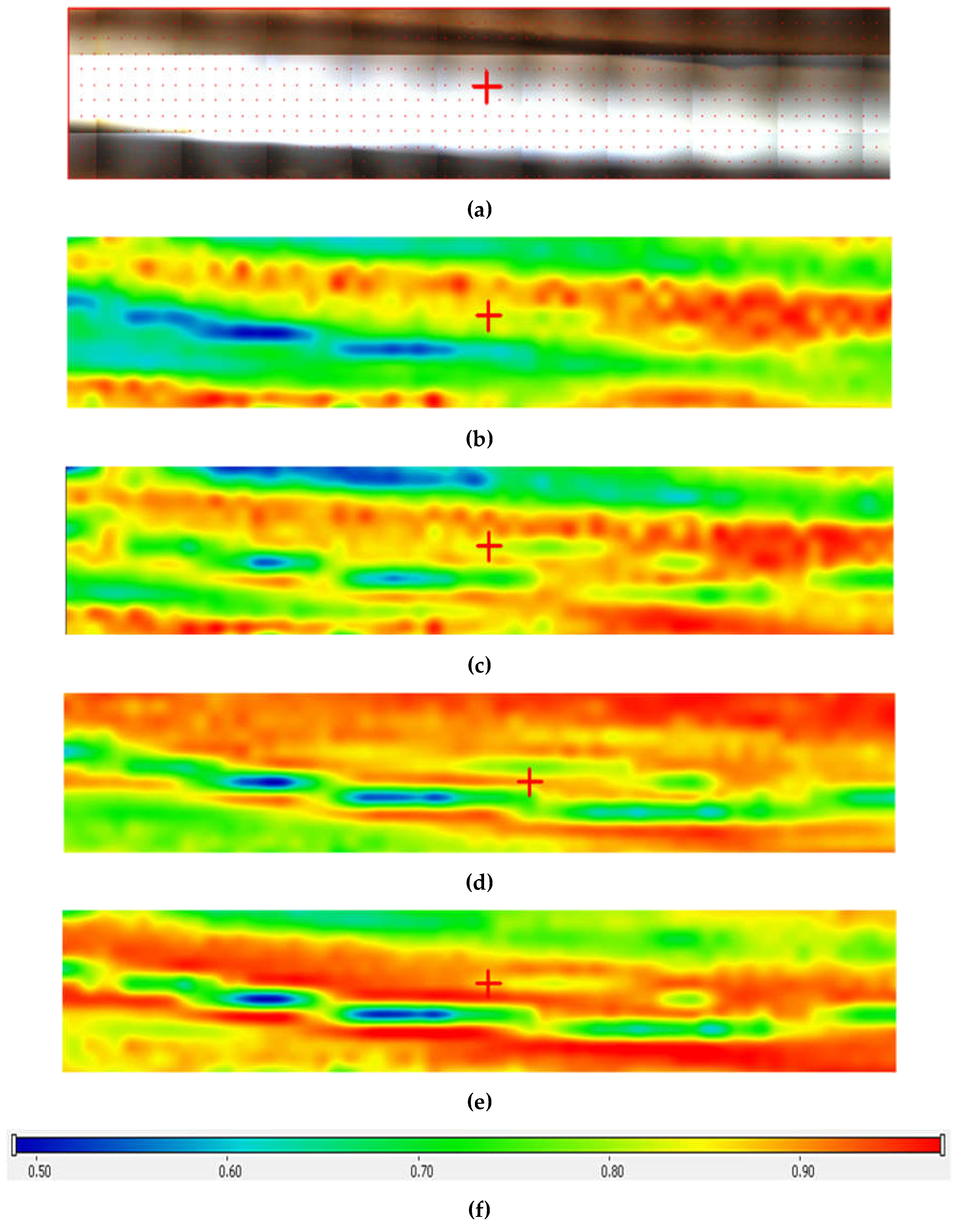
Figure 8.
Structural characterization of composite membranes by EDAX for membranes: (a) P1; (b) P2 before the hydrogen sulfide retention process; and (c) P5 after retention of hydrogen sulfide as cadmium sulfide.
Figure 8.
Structural characterization of composite membranes by EDAX for membranes: (a) P1; (b) P2 before the hydrogen sulfide retention process; and (c) P5 after retention of hydrogen sulfide as cadmium sulfide.
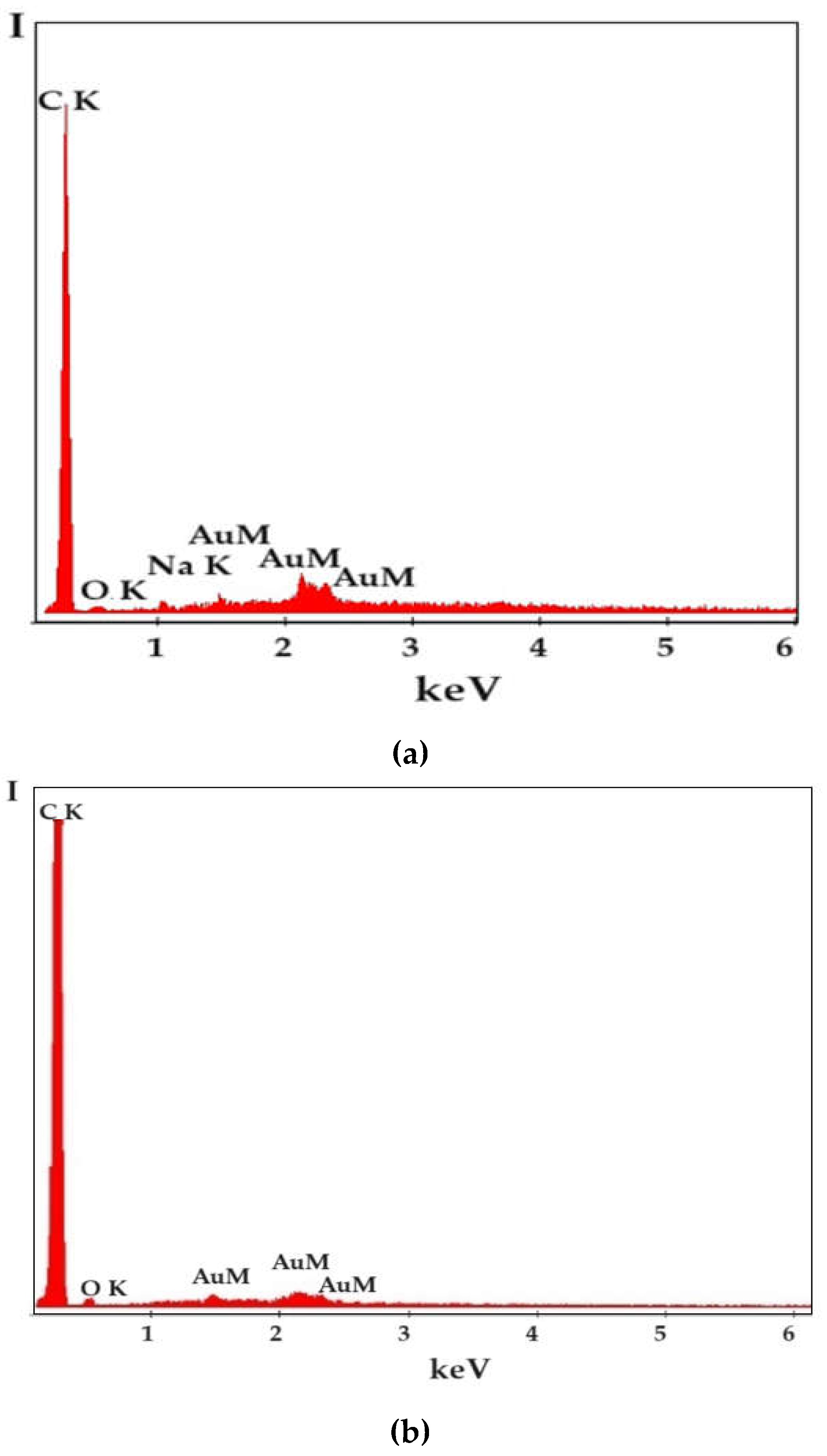
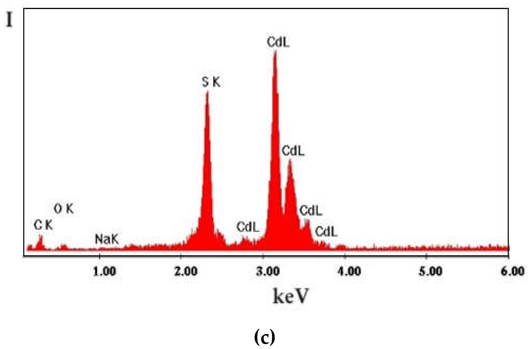
Figure 9.
Thermal diagrams for the four composite membranes (P1, P2, P3 and P4): (a) integral diagram; (b) onset diagram.
Figure 9.
Thermal diagrams for the four composite membranes (P1, P2, P3 and P4): (a) integral diagram; (b) onset diagram.
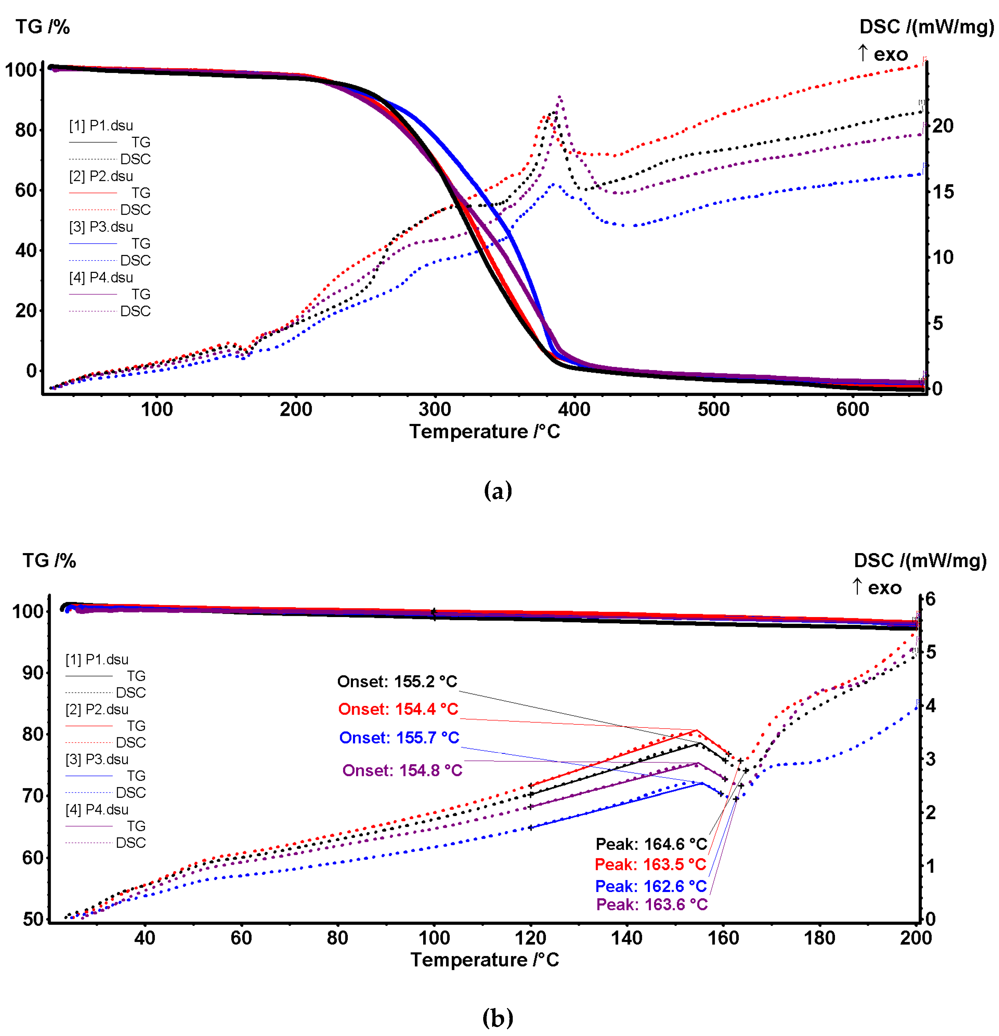
Figure 11.
The TG-DSC curves for P5 sample (membrane P1 after retention hydrogen sulfide as CdS).
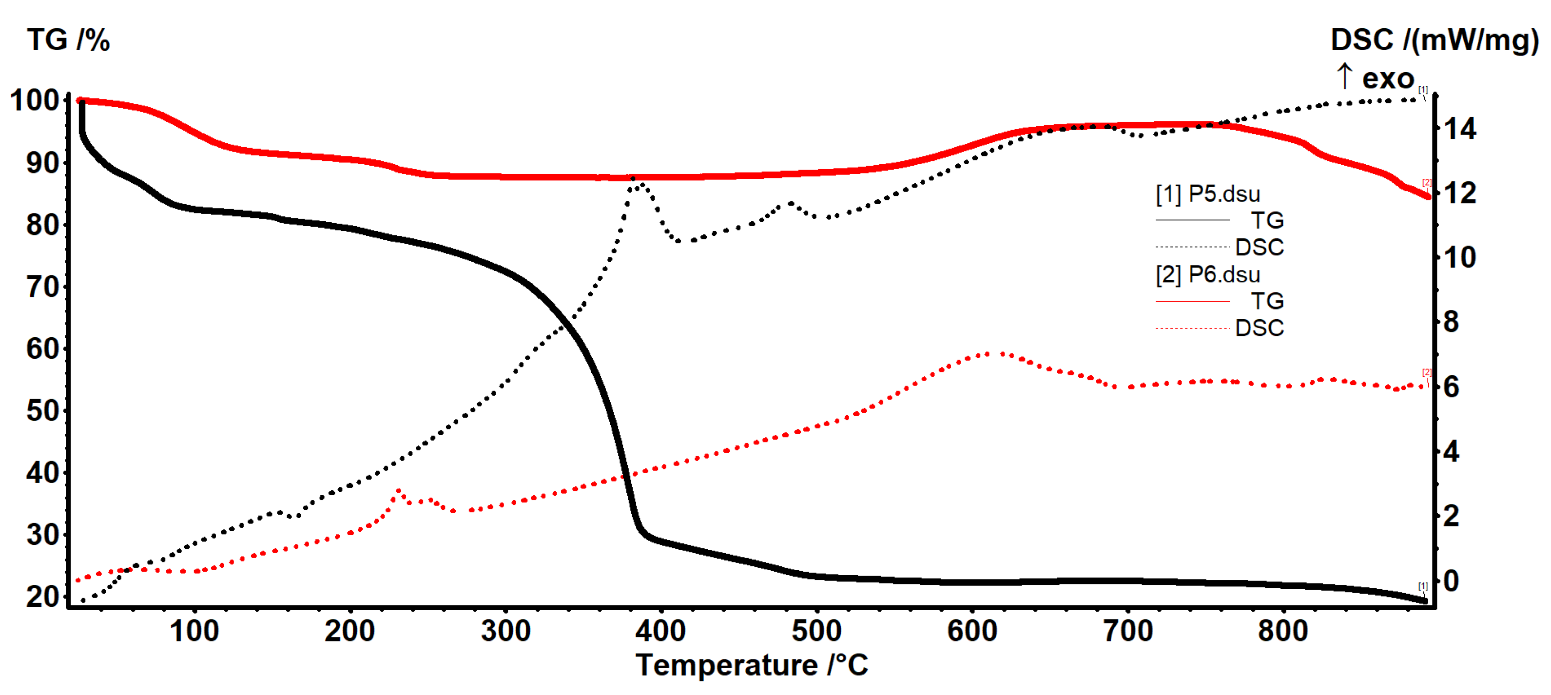
Figure 12.
The thermal analysis (TG and DSC curves) for sample P6 (CdS from retention hydrogen sulfide on membrane P1).
Figure 12.
The thermal analysis (TG and DSC curves) for sample P6 (CdS from retention hydrogen sulfide on membrane P1).
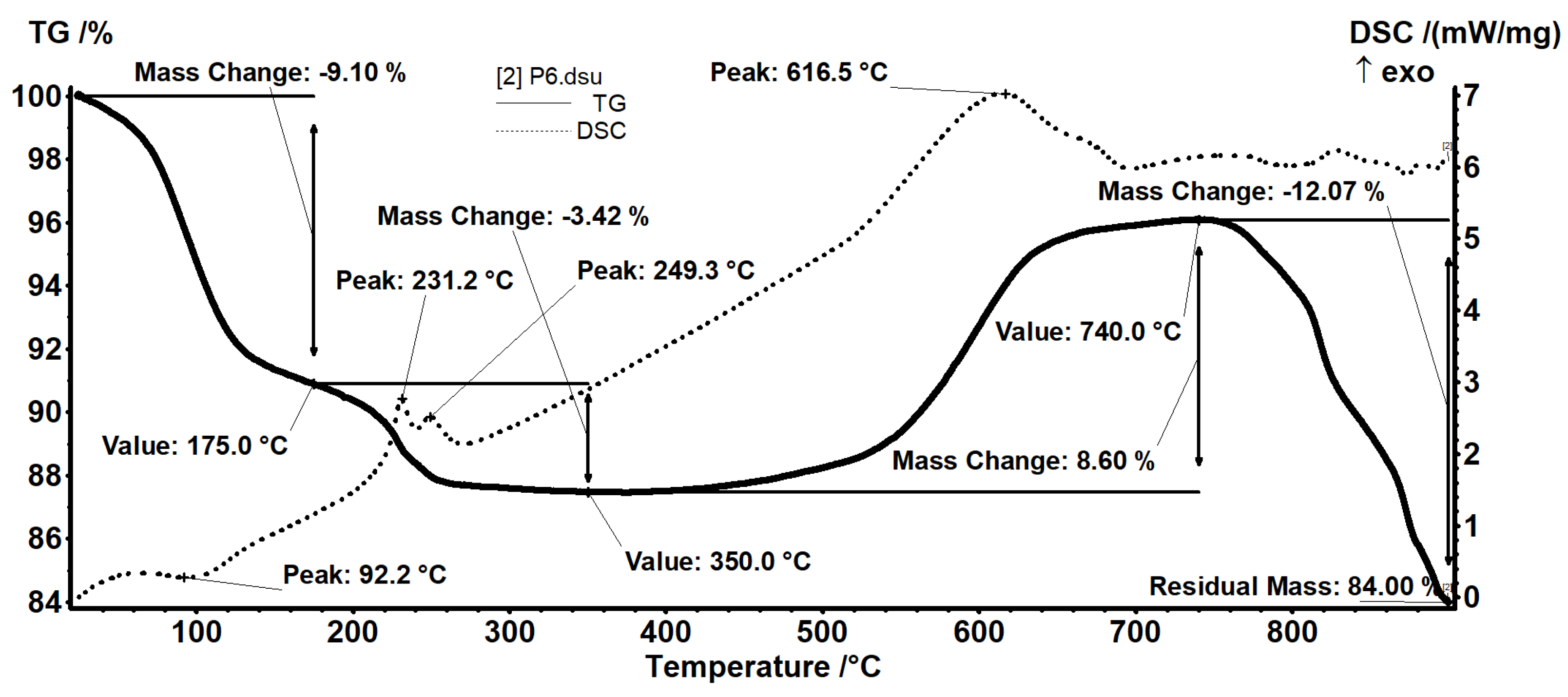
Figure 13.
The variation of pertraction efficiency (PE%) as a function of time for the following membranes: sodium carboxymethyl–cellulose–polypropylene hollow fiber (P1), cellulose acetate–polypropylene hollow fiber (P2), methyl 2–hydroxyethyl–cellulose–polypropylene hollow fiber (P3), and 2–hydroxyethyl–cellulose–polypropylene hollow fiber (P4).
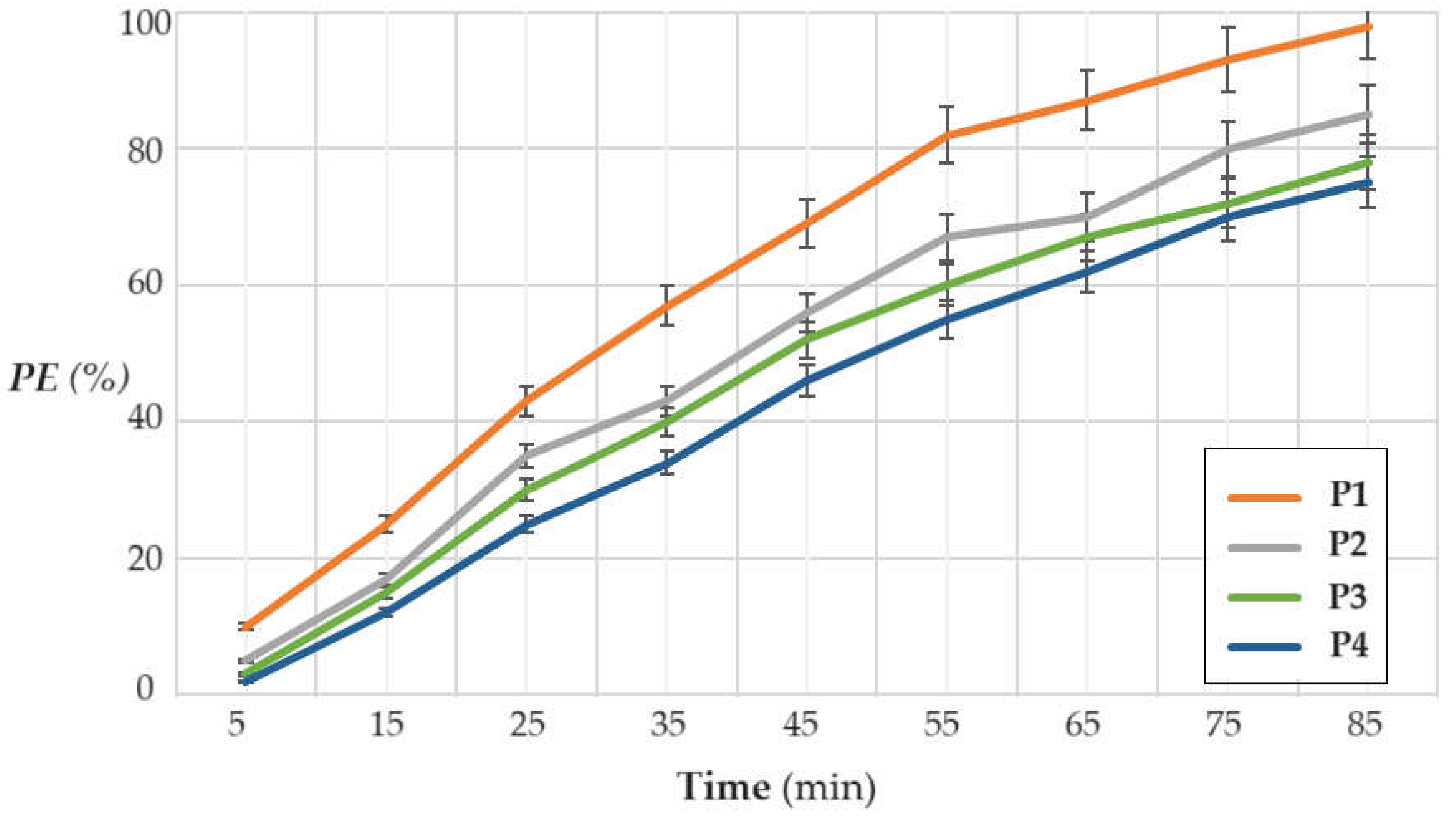
Figure 14.
The variation of the pertraction efficiency depending on the operating time, at hydrogen sulfide concentrations of 20, 40 and 60 ppm, for the membrane sodium carboxymethyl–cellulose–polypropylene hollow fiber (P1).
Figure 14.
The variation of the pertraction efficiency depending on the operating time, at hydrogen sulfide concentrations of 20, 40 and 60 ppm, for the membrane sodium carboxymethyl–cellulose–polypropylene hollow fiber (P1).
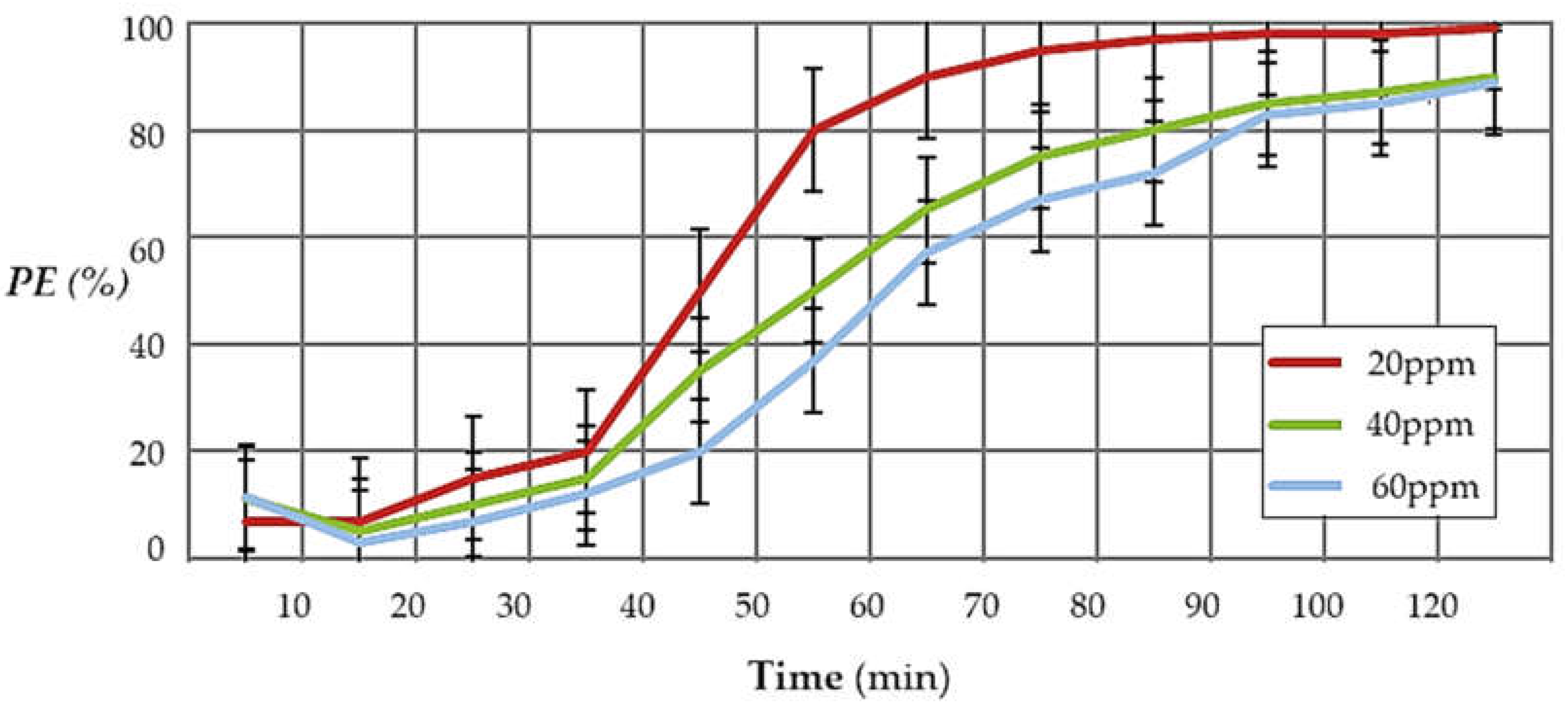
Figure 15.
The variation of hydrogen sulfide pertraction efficiency as a function of time and flow rate of polluted air for the composite membrane P1, air volume of 5 m3, concentration of 60 ppm and pH=2 in the receiving phase.
Figure 15.
The variation of hydrogen sulfide pertraction efficiency as a function of time and flow rate of polluted air for the composite membrane P1, air volume of 5 m3, concentration of 60 ppm and pH=2 in the receiving phase.
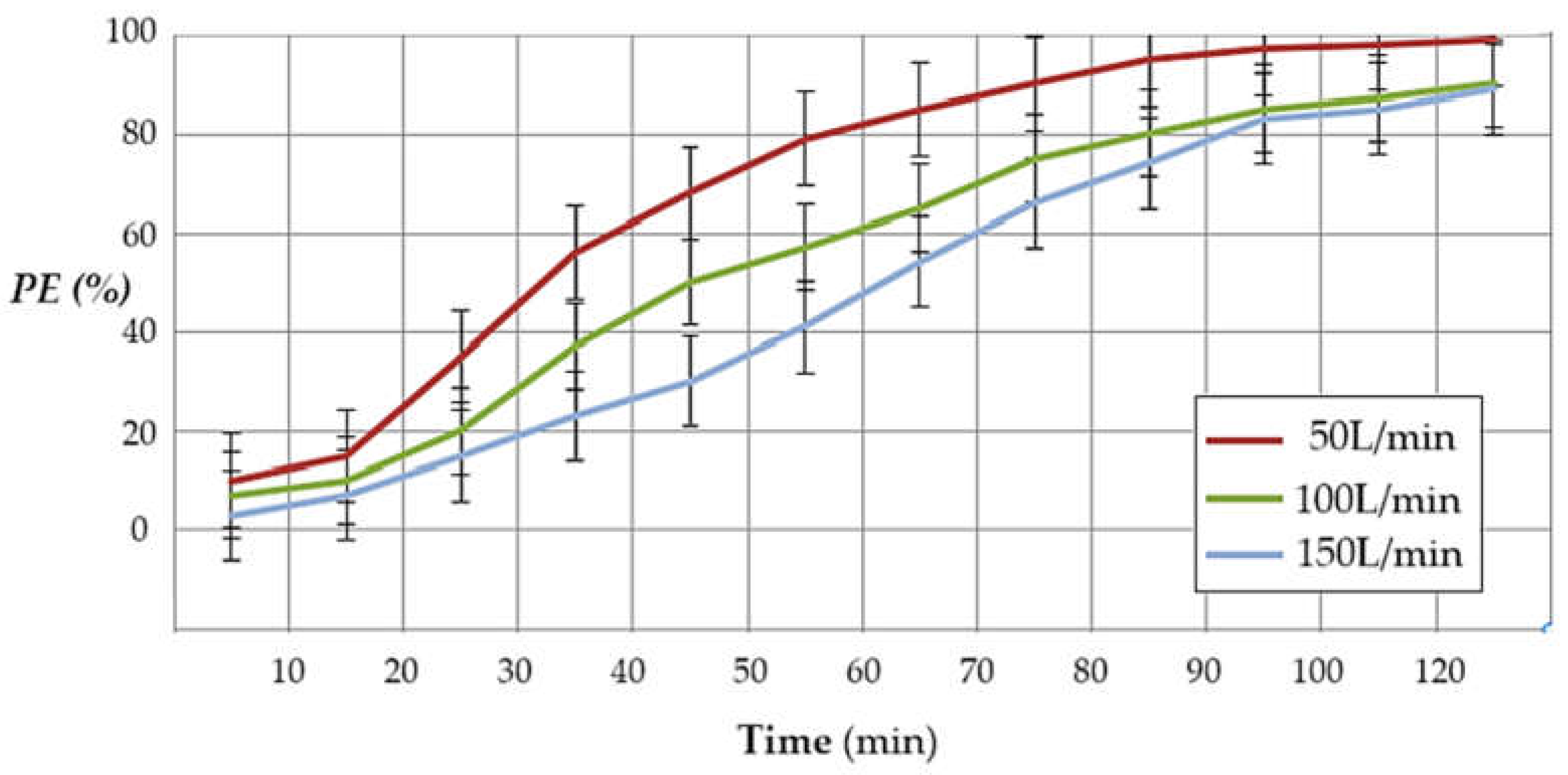
Figure 16.
Scanning electron microscopy (SEM) for membrane P1 coated with cadmium sulfide following hydrogen sulfide pertraction in a cadmium nitrate solution: (a) membrane section after the hydrogen sulfide recovery process as CdS; (b) membrane view at 100× resolution; (c) membrane view at 500× resolution; and (d) membrane view at 1000× resolution.
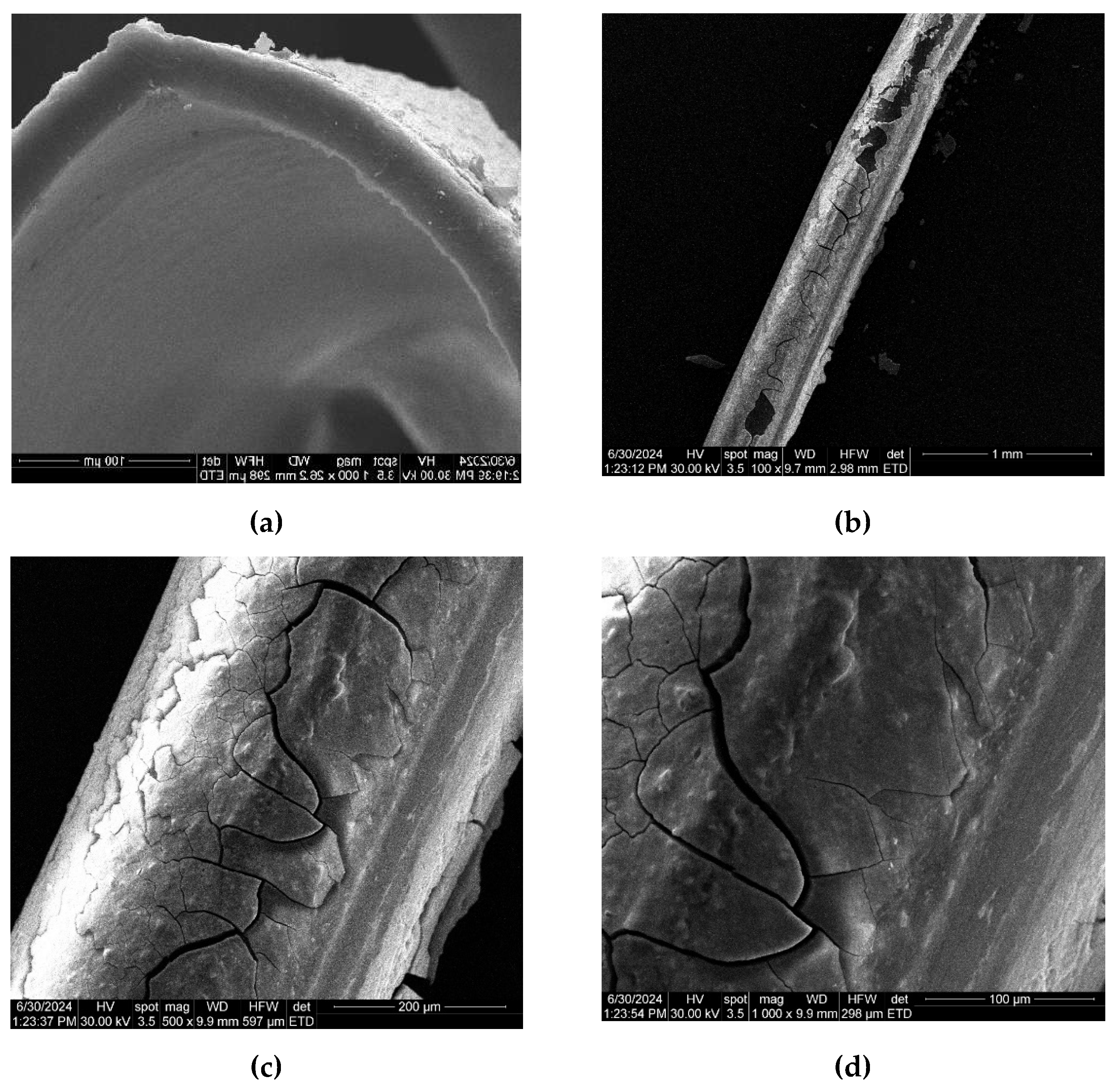

Table 1.
The characteristics of the tested cellulosic derivatives and the obtained membranes.
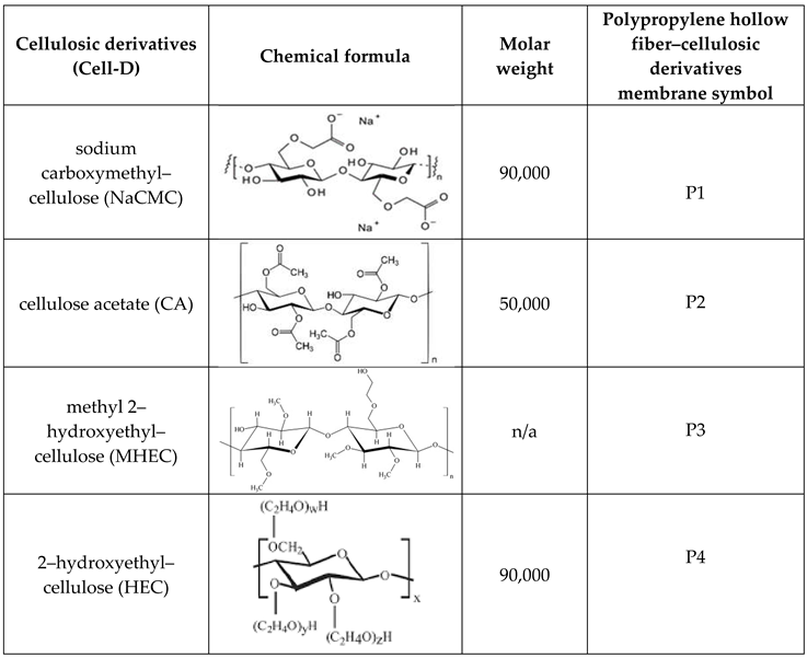
Table 2.
Principal numerical data from thermal analysis for P1–P4 samples.
| Sample | T5% (°C) |
T10% (°C) |
T50% (°C) |
Mass loss % RT–200 °C |
Melting onset (°C) |
Melting peak (°C) |
Exothermic effect (°C) |
|---|---|---|---|---|---|---|---|
| P1 | 235 | 264 | 322 | 2.88 | 155.2 | 164.6 | 384.1 |
| P2 | 230 | 252 | 325 | 2.12 | 154.4 | 163.5 | 379.5 |
| P3 | 227 | 260 | 346 | 2.48 | 155.7 | 162.6 | 385.8 |
| P4 | 224 | 247 | 331 | 2.50 | 154.8 | 163.6 | 389.3 |
Table 3.
Dependence of hydrogen sulfide pertraction efficiency on the pH of the receiving phase.
| pH of receiving phase | 0 | 2 | 4 | 6 |
|---|---|---|---|---|
| PE (%) | 86.3 | 98.3 | 97.2 | 89.6 |
Disclaimer/Publisher’s Note: The statements, opinions and data contained in all publications are solely those of the individual author(s) and contributor(s) and not of MDPI and/or the editor(s). MDPI and/or the editor(s) disclaim responsibility for any injury to people or property resulting from any ideas, methods, instructions or products referred to in the content. |
© 2024 by the authors. Licensee MDPI, Basel, Switzerland. This article is an open access article distributed under the terms and conditions of the Creative Commons Attribution (CC BY) license (http://creativecommons.org/licenses/by/4.0/).
Copyright: This open access article is published under a Creative Commons CC BY 4.0 license, which permit the free download, distribution, and reuse, provided that the author and preprint are cited in any reuse.


