Submitted:
17 July 2024
Posted:
17 July 2024
You are already at the latest version
Abstract
This paper presents a demonstration of a linearly-polarized transmit-arrays antenna with high-efficiency and wideband operating in X-band. The topology of the unit cell consists of two identical patch antennas loaded by C-loop slot and interconnected by a metalized via through a ground plane sandwiched between two identical substrates [18]. A waveguide measurement system WGMS has been used for single cell characterization (reflection/transmission coefficients). Good results have been demonstrated in terms of matching performances; the reflection coefficient S11 is under 10-dB in the 9.4-10.4 GHz band (i.e. 10.1% around 9.9 GHz) and with only 0.35 dB-insertion loss at 10 GHz. The transmit-arrays prototype permitted to achieve 22.4 dBi of directivity and 20.1 dBi of gain. The aperture and radiation efficiencies are about 28.2% and 58.3%, respectively. With a focal ratio (F/D) of 1/2 the spill-over loss is less than 2 dB. Beam-scanning up to ± 35° has been achieved with the same phase quantization (passive) and less than 3 dB of gain losses.
Keywords:
Transmit-arrays
; Planar Antenna
; lens antenna
; Phased array
; Beam-steering
; Beam-scanning
; Unit cell
; Circular patch
; X-band
1. Introduction
TRANSMIT-ARRAY (TA) antennas (TAA) have been discovered more than twenty years ago [1,2]. Since few years, they became very attractive antennas for millimeter applications [3,4,5,6] and more popular than the traditional reflectors because they can be flat and thereby occupy less space with low-profile. The TAA can be also a potential candidate for the base station antennas of the next-generation of the mobile communication (5-6G). The configuration of transmit-arrays (Figure 1) consists of a first receive antennas array illuminated by a primary spatial source and a second transmit antennas array that reradiates the signal received by the first array after obtaining the required wave transformation [5,6]. The two antennas arrays are inter-connected by intermediate circuits that permit to control the phase and amplitude of each transmit-array element.
The TAA can be compared to some kind of antennas such; traditional antennas array, reflectors, lens antennas and reflect-arrays [7,8]. However, the TAA presents several advantages which consist in its topology that gives more freedom degrees; i) the focal source (FS) is placed away of the radiation region and solves the blockage problem caused by the FS, ii) two antennas arrays (receiving & transmitting sides) can be designed and controlled separately compared to the reflect-array antennas where often single antennas array should receive and re-transmit the waves, and iii) the circuits of amplitude/phase control can be sandwiched between the two arrays without impacting the electric field.
The applications of the TAA are diverse and varied; such, tracking radar, automotive, driving assistance, high data rate wireless, satellites, communication and imaging systems.
Many configurations of TA cell have been proposed and demonstrated in different frequency bands [5,6,9,10,11]. The reconfigurable TA have been also demonstrated based on different techniques and technologies such; MEMS-RF, semiconductor and PIN diodes [12,13,14].
The principal investigation and contribution of this research work is the attractive unit cell (UC) with only tri-layer structure that offers a simple phase control and polarization switching. The topology of the presented UC consists of two identical circular patch antennas interconnected by a metalized via hole and loaded by a C-loop slot and features a perfectly symmetric cell, which ensures a small size and low-profile, qualify this proposed UC to be an attractive (excellent) candidate for mmWave applications. The simplicity of the UC permits a fabrication with a standard printed-circuit board fabrication technology.
2. Unit Cell Concept
The challenge of this research work consists to design a novel UC with more features, i.e. that can be used for linear and circular polarization (LP & CP) and offering additional phase-delay states compared to the previous design [15]. The ability to switch between LP and CP permits to reduce the interference between the primary feed radiation and the array radiation (perfectly polarization decoupling).
The concept of the UC is illustrated in Figure 2. Based on the previous design [15], this design has started by replacing the square patch by circular one. The next steps of designing process will be presented along the paper. This UC is composed of two back-to-back identical circular patch antennas interconnected in their centers by a metalized via hole passing through a common ground plane sandwiched between two substrates (upper and lower). A C-loop slot is placed in the center of the patch antenna in the aim to modify the current lines on the patch surface and matches the impedance between the two patch antennas. This C-loop permits also to orient the direction of the electric field. However, without the C-loop slot and with only a via hole placed in the center of the patch antennas, there is not coupling between the two patch antennas because the magnitude of the E-field is null in this point of connection (orientation changing, up-down).
The different configurations of the unit cell permitting a 1-/2-bit phase quantization are obtained by orienting the direction of the electric field (i.e. by rotating the C-loop slot). Depend on the electric field orientation, the 1-bit (2 states, linear polarization) or 2-bit (4 states, circular polarization) transmit-array can be designed.
This UC is a dual polarization design. The incident wave with the appropriate polarization (LP) is received by the first patch antenna in the input side, passes through the via hole, and reradiates from the second patch antenna with linear or circular polarization (section 3). For the linear polarization the opposite/orthogonal polarization is related to the C-loop slot orientation; i.e. related to the position of the C-loop gap.
The coupling between the two antennas is guaranteed by the C-loop slot and the via hole together. The essential challenge, after fixing the antenna dimensions, is the coupling (matching) level between the two elementary antennas. This coupling is controlled by the dimensions of the C-loop slot/gap and the diameter of the via hole.
The patches in the focal source side have the same orientation for all the UCs (as reference), while the patches in the free space side are rotated by an angle α, providing therefore a polarization rotation and a transmission phase-shift, as presented in Figure 2. For linearly polarized UC, the α-values are 00° and 180° (or 90° and 270°) for the two transmission phase values with 180° phase difference (1-bit phase quantization), while for circularly polarized transmit-arrays the four cells must be used (2-bit phase quantization, CP is formed by the two orthogonal LP).
3. Unit Cell Design
As introduced in the section 2, that the coupling between the two patches cannot be achieved with only a via hole placed in the center. However, for modifying the impedance near the metalized via and improving the coupling, a quasi-loop slot “C-shape” has been inserted in the center of the patch antennas. A parametric study has been done to evaluate the impact of the different parameters of the added C-loop slot (such: radius, gap width, loop width ...) on the performances of the UC and select optimal cell in terms of impedance matching.
3.1. Linearly Polarized Unit Cell
The dimension of the UC is 15×15 mm² (λ0/2× λ0/2 at 10 GHz). They benefit from small size and low loss, thus allowing spacing cells of λ0/2 in both directions. The two identical patch antennas (∅ = 8.3 mm) are connected by a via hole (∅ = 300 µm) through the substrates and separated by a ground plane (thickness 17 µm). The both used substrates are Rogers RO4003 (εr = 3.38, tanδ = 0.0027, thickness 1.524 mm). A 40 µm-thickness bonding film has been placed between the bottom substrate and the ground plane.
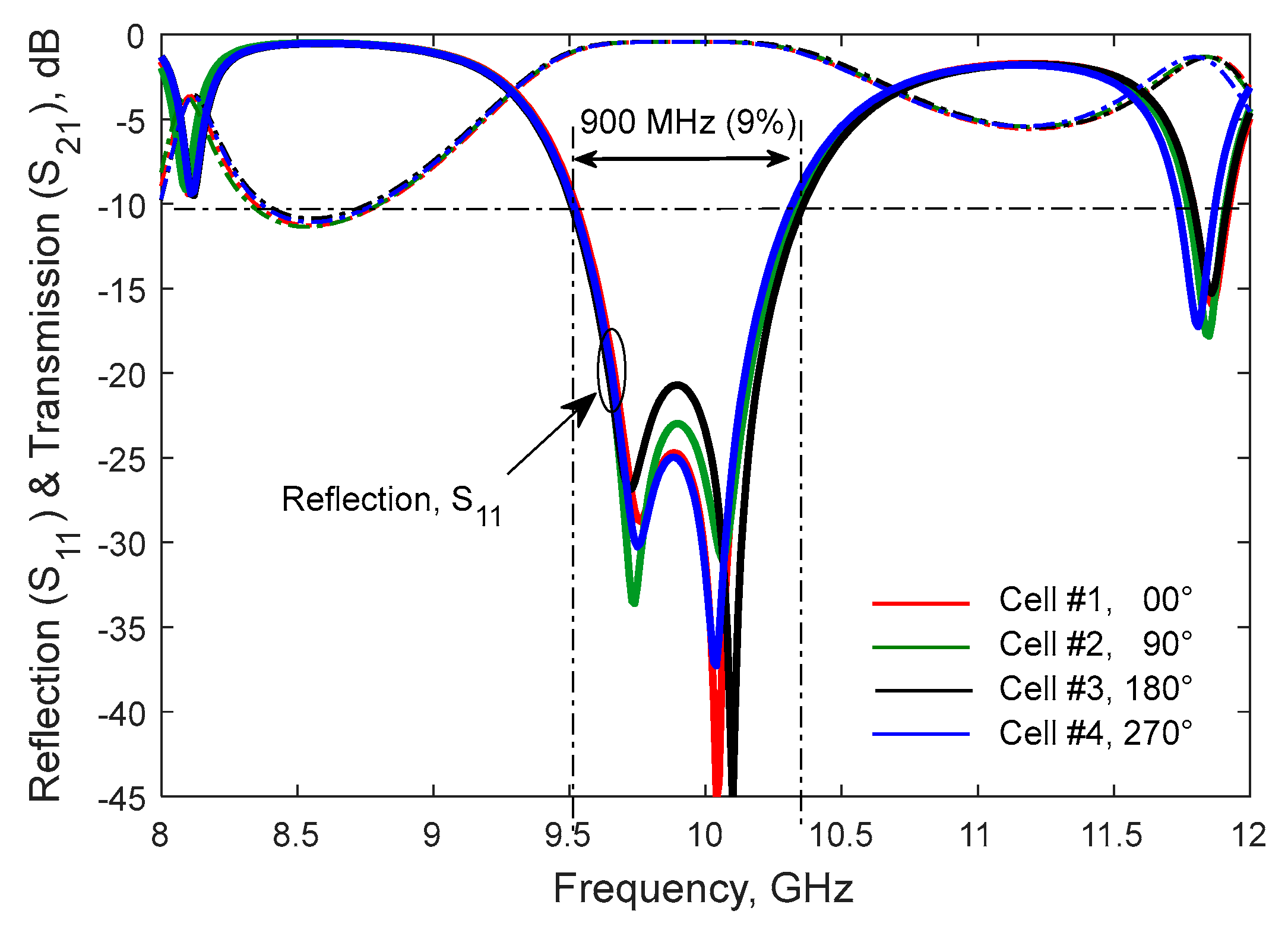
The simulated S-parameters of the four unit cells illuminated by a plane wave under normal incidence are presented in the Figure 4. These UCs exhibit a similar performance and good coupling/matching level.
A 10-dB reflection coefficient is obtained in the 9.4-10.4 GHz band (10.1% around 9.9 GHz). The insertion loss is 0.35 dB at 9.9 GHz.
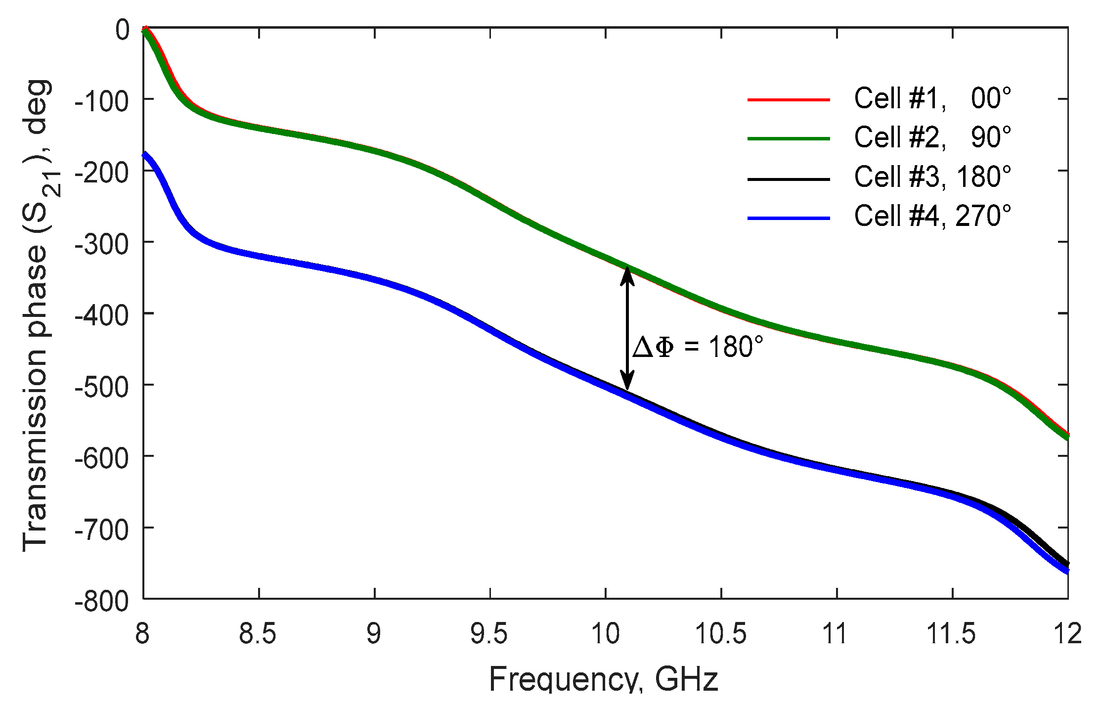
The difference of the transmission phase between the both couples of UCs (cells #1&3 and cells #2&4) is 180° along all the frequency band, which guarantees a perfect 1-bit phase compensation, Figure 4.
The radiation pattern of the patch antenna simulated at 10 GHz is presented in Figure 3. This simulation is done with a small lumped port excitation between the ground plane and the metalized via and periodic boundary conditions on the lateral sides.
This simulation shows a 4.7-dBi of gain and 86° of HPBW in E- and H-planes.
Figure 3.
Simulated gain of the UC computed at 10 GHz.

Figure 4.
The S-Parameters, amplitude and phase, of the four UCs.
3.2. Circularly Polarized Unit Cell
The circular polarization is obtained by just modifying the form of radiating element (patch antenna) as illustrated in the Figure 5.
The circular patch has been loaded by notch cut at opposite and appropriate positions on the antenna edges. The idea consists to degenerate the fundamental TM11 mode into two orthogonal modes and thereby produce the circular polarization. The three designs have been studied and compared in terms of radiation performances (gain and axial ratio). In Figure 6, the E-field distribution (magnitude) on surface of patch antenna is presented for different phases (RHCP case). As can be remarked on this distribution of the E-field, the circular polarization is achieved but the CP ratio (AR, axial ratio) must be improved, see Figure 7. The improving of the axial ratio is in process and the results may be published with another research work.
4. Unit Cell Characterization
The transmission and reflection coefficients of UC can be measured with different techniques; i) in free-space using the Gaussian optics measurement system (GOMS) [16], ii) by shining a large sample with a plane wave in the anechoic chamber, or iii) by replacing a single unit cell or a small sample in a waveguide (WGMS) [17].
Since the UC is symmetric and operating in X-band, the waveguide measurement system has been chosen, with standard WR90 waveguide, due to the facility access to the reflection coefficient, Figure 8. This measurement method is more detailed in [17].
The S-parameters of the UC are presented in Figure 9, which indicate a very good agreement.
5. Transmit-Array Design & Simulation
In this section, the design and simulation of a full transmit-arrays antenna is discussed. Because of the in-house fabrication constraints (such, the A4 format substrate sheet), the size of the array was limited to 14x14 cells (196 cells), Figure 10. Based on the results presented in the Table 1 and Table 2, the focal distance of 105 mm (F/D=1/2) and the 1-bit phase quantization have been selected.
In the Table 1, the impact of the phase correction on the radiation performances of the TAA is shown. The 1-bit et 2-bit quantization are good compromise between the quantization loss and the design complexity.
The Table 2 summarizes the impact of the position of the focal source (F focal distance, see Figure 1) on the radiation performances of the TA antenna. The main objective of this study is to identify the best compromise between aperture efficiency and the radiation efficiency, i.e. between the directivity and the spill-over loss. However, when the F increases the illumination energy becomes more linear, which improves the directivity while the spill-over loss increase, which reduces the gain (radiation efficiency).
For the applications of interest, the optimal focal distance is F=105 mm. For this chosen distance, the directivity and gain are 22.4 and 20.1 dBi which give a radiation and aperture efficiency of 58.3% and 28.2 %.
The variation of the directivity, gain and efficiencies as function of frequency are presented in the Figure 11 and Figure 12. The variation of the radiation efficiency is similar to the gain, while the variation of the aperture efficiency is similar to the directivity. The radiation efficiency is more than 50% between 9.3 GHz and 10 GHz.
The Figure 13 presents the radiation pattern of the designed TA antenna and the effect of a focal source misalignment (15-mm source drift along x-axis). The Figure 14 shows the difference between a perfect and 1-bit phase quantization.
The Figure 15 presents the radiation pattern of the TAA with beam-scanning achieved by two different methods. The position A is the initial position of the focal source for which the phase quantization was generated. For the position B, the focal source is tilted along a focal arc keeping the same distance between the source and the arrays. However, for the position C, the focal source is shifted along X-axe.
The second method can be easily realized compared to the first one (source tilting along a focal arc). In term of the radiation performances the first method looks to be better than the method (source translation) due to the phase error and the illumination symmetry.
6. Transmit-Array Measurement
The prototype presented in the Figure 10 is an in-house fabrication. It has been manufactured by reducing the technical constraints (diameter of the via hole, width and GAP of the C-loop, thickness of the bonding film ...) imposed by the limitations and restrictions of our technological environment and the available resources. Since the available substrate sheet is A4-format, the array has been limited at 14x14 cells.
In-house mechanical support (Figure 10a) has been designed and fabricated in the aim to allow focal source tilting as explained in the Section 5 (second method). The focal source (Figure 10b) is also an internal fabrication based on a coaxial cable to waveguide WR90 transition as the one used in the measurement setup of the unit cell presented in the section 4, Figure 8)
This TA prototype has been characterized in the anechoic chamber of the LAPLACE laboratory (GRE team), Figure 16.
The Figure 17 presents the measured radiation patterns in the H-plane (rotation along Z-axe) with different angles (up to 35°) of focal source tilting.
The measured gain is 18.4 dBi and the sidelobe level SLL is 14.9 dB. The 1.7 dB-difference between the simulated and measured gain is acceptable because it is in the scope of the realization precision and the measurement tolerance.
The beam-scanning (beam-steering) capability has been demonstrated by just tilting the focal source (FS) along a focal-arc. With a fixed phase law and 25°-FS tilting, the main lobe is steered at 28.6° by losing only 1.7 dB of gain. However, at 38.6° (35°-FS tilting), the gain is reduced of 4.6 dB. The 3.6° of steering difference is caused by the phase error of the passive TA compared to the active one.
To achieve a large angle of steering, the phase law must be modified to compensate the phase error. The passive prototype is limited at 30° of beam-steering capability when a 1.7 dB of gain reducing is tolerated.
7. Conclusions
An attractive wideband unit cell for transmit-arrays antennas for mmWave application has been proposed and designed. A full TA prototype has been demonstrated at 10 GHz (X-band). The presented unit cell has been designed and simulated using the finite element method, and characterized with the waveguide measurement system (WGMS). A very good agreement is obtained between simulation and measurement. The study, design and characterization of the full TA antenna with beam-scanning have been discussed. The important design parameters and their impact on the antenna performances have been presented. The characterization of the full prototype in an anechoic chamber has been presented in terms of radiation pattern and shows a good agreement with the simulation results.
Acknowledgment
The authors would like to thank Toulouse-INP for the financial support granted in the TTI-JR collaboration.
References
- D. Popovic and Z. Popovic, “Multibeam antennas with polarization and angle diversity,” IEEE Trans. Antennas Propag., vol. 50, no. 5, pp. 651–657, May 2002. [CrossRef]
- D. M. Pozar, “Flat lens antenna concept using aperture coupled microstrip patches,” Electronics Letters, vol. 32, no. 23, pp. 2109–2111, Nov. 1996. [CrossRef]
- S.-Q. Xiao, M.-T. Zhou, and Y. Zhang, “Millimeter wave technology in wireless PAN, LAN, and MAN,” CRC Press, 2008.
- H. Kaouach, A. Kabshi “Simple Tri-Layer Linearly Polarized Discrete Lens Antenna with High-Efficiency for mmWave Applications”, IEEE Antennas and Wireless Propag. Letters, vol. 15, pp. 259-262, 2015. [CrossRef]
- H. Kaouach, “Design and characterization of circularly-polarized discrete lens antennas in 60-GHz,” IEEE Antennas and Wireless Propagation Letters, vol. 15, pp.1200-1203, 2016. [CrossRef]
- H. Kaouach, A. H. Kaouach, A. Kabashi, F. Ouasli, “High-Efficiency Wideband Transmit-array Antenna with Linear Polarization in Q-Band,” Elsevier, AEUE - International Journal of Electronics and Communications, vol. 70, no. 9, pp. 1275-1281, Sept. 2016. [CrossRef]
- J. Lanteri, C. Migliaccio, J. Y. Dauvignac, Ch. Pichot, “Reflectarray using an offset prolate feed at 94 GHz,” IEEE Antennas and Propag. Soc. Int. Symp. (AP-S/URSI ’08), San Diego, CA, USA, 2008. [CrossRef]
- D. Pozar, S. Targonski, H. D. Syrigos, “Design of millimeter wave microstrip reflect-arrays,” IEEE Trans. Ant. Propag., vol. 45, no. 2, pp. 287–295, 1997. [CrossRef]
- H. Kaouach, L. Dussopt, R. Sauleau, Th. Koleck, “Design and demonstration of 1-bit and 2-bit transmit-arrays at X-band frequencies,” European Microwave Conference, Roma, Italy, 28 Sept.-1 Oct. 2009. [CrossRef]
- A. Abbaspour-Tamijani, K. Saranbandi, G.M. Rebeiz, “A millimeterwave bandpass filter-lens array,” IET Microwaves Antennas and Propagations, vol. 1, no. 2, pp. 388-395, 2007. [CrossRef]
- P. Padilla de la Torre, M. Sierra-Castañer, M. Sierra-Perez, “Design of a double array lens,” European Conference on Antennas and Propagation (EuCAP), Nice, France, Nov. 2006. [CrossRef]
- C-C. Cheng, B. Lakshminarayanan, A. Abbaspour-Tamijani, “A programmable lens-array antenna with monolithically integrated MEMS switches,” IEEE Transactions on Microwave Theory and Techniques, vol. 57, no. 8, pp. 1874-1884, 2009. [CrossRef]
- A. Muñoz-Acevedo, P. Padilla de la Torre, M. Sierra-Castañer, “Ku-band active transmitarray based on microwave phase shifters,” European Conf. on Antennas and Propag., Berlin, Germany, March 23-27, 2009, https://ieeexplore.ieee.org/document/5067830.
- Clemente, L. Dussopt, R. Sauleau, P. Potier, P. Pouliguen,“Wideband 400-Element Electronically Reconfigurable Transmitarray in X Band,” IEEE Tran. on Antennas and Propag., vol. 61, no. 10, p. 5017-27, 2013.
- H. Kaouach, M. A. Belaid, “Tri-Layer linearly polarized discrete lens antenna operating in X band, design and characterization,” Elsevier, AEUE - International Journal of Electronics and Communications, vol. 86, pp. 117-124, March 2018. [CrossRef]
- H. Kaouach and A. Kabashi, “Using gaussian optics measurement system to characterize a new wideband low-loss antenna-slot-antenna,” IEEE CAMA’14, Nov 2014, Antibes Juan-les-Pins, France. [CrossRef]
- H.Kaouach, F. ouasli, “Design and characterization of wideband high-efficiency unit cells for frequency selective surfaces in 10GHz-band,” IEEE-ICEAA, International Conference on Electromagnetics in Advanced Applications, Torino, Italy, September 7-11, 2015. [CrossRef]
- H. Kaouach and O. Pigaglio, “Linearly Polarized Unit-Cells for Transmit-Arrays Operating in mmWave Bands,” 2019 International Conference on Electromagnetics in Advanced Applications (ICEAA), Granada, Spain, 2019, pp. 1-4. [CrossRef]
Figure 1.
The typical configuration of transmit-arrays in Tx-mode.
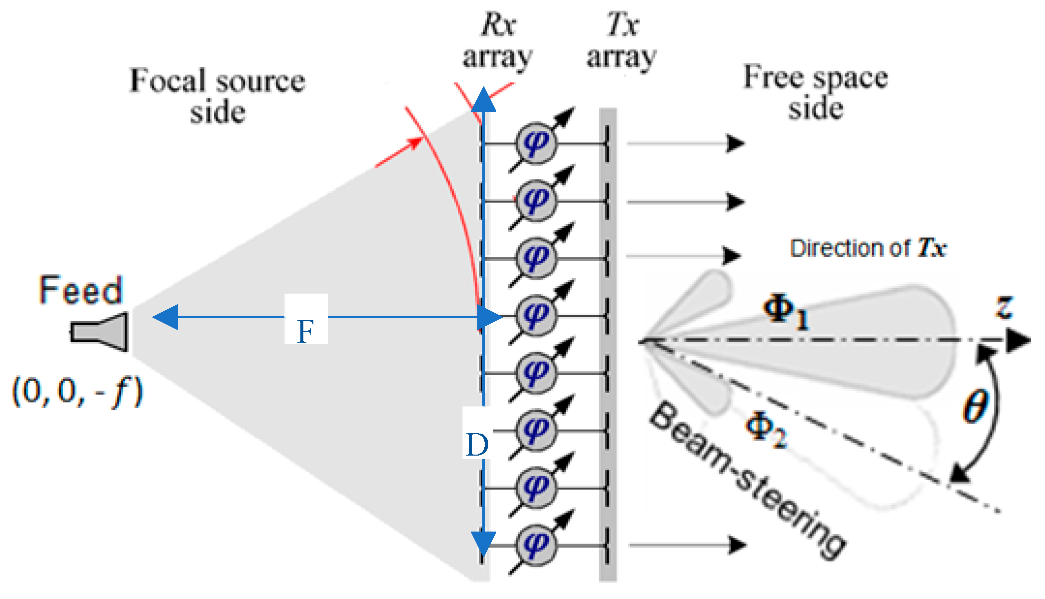
Figure 2.
Design and topology of the proposed unit cell.
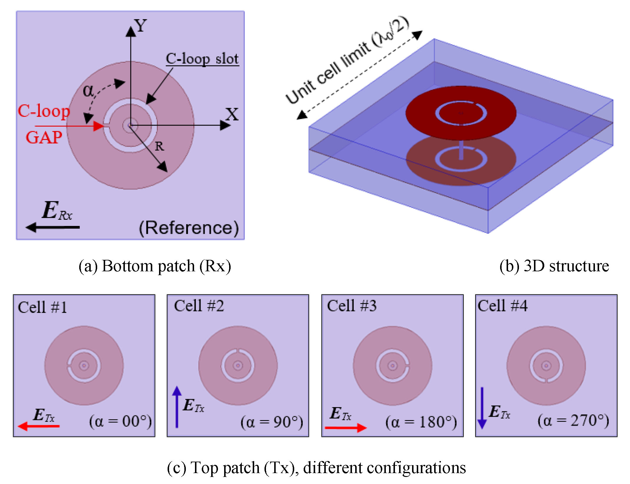
Figure 5.
The different designs of the circularly polarized patch.
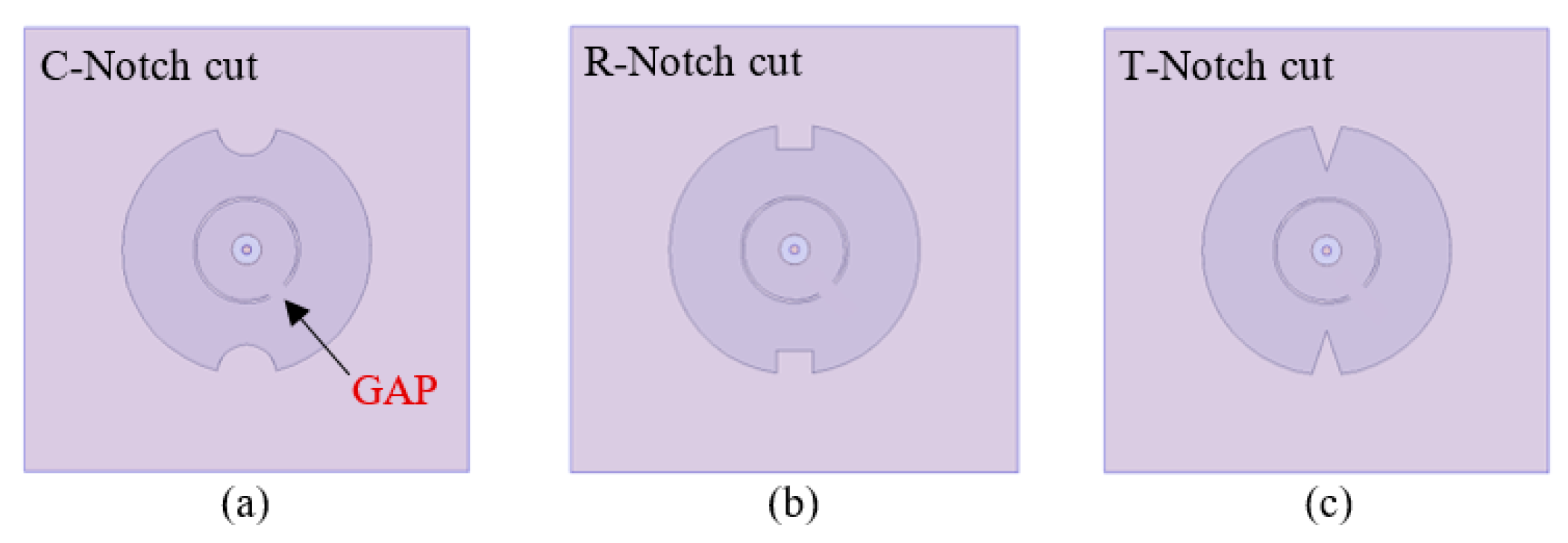
Figure 6.
Magnitude distribution of E-field demonstrating a RHCP.
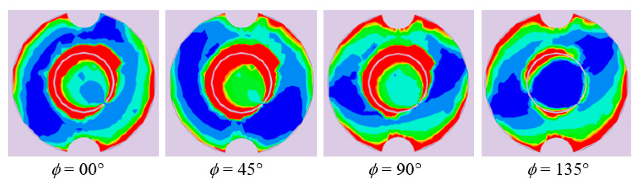
Figure 7.
Variation of the axial ratio for the circularly polarized unit cells.
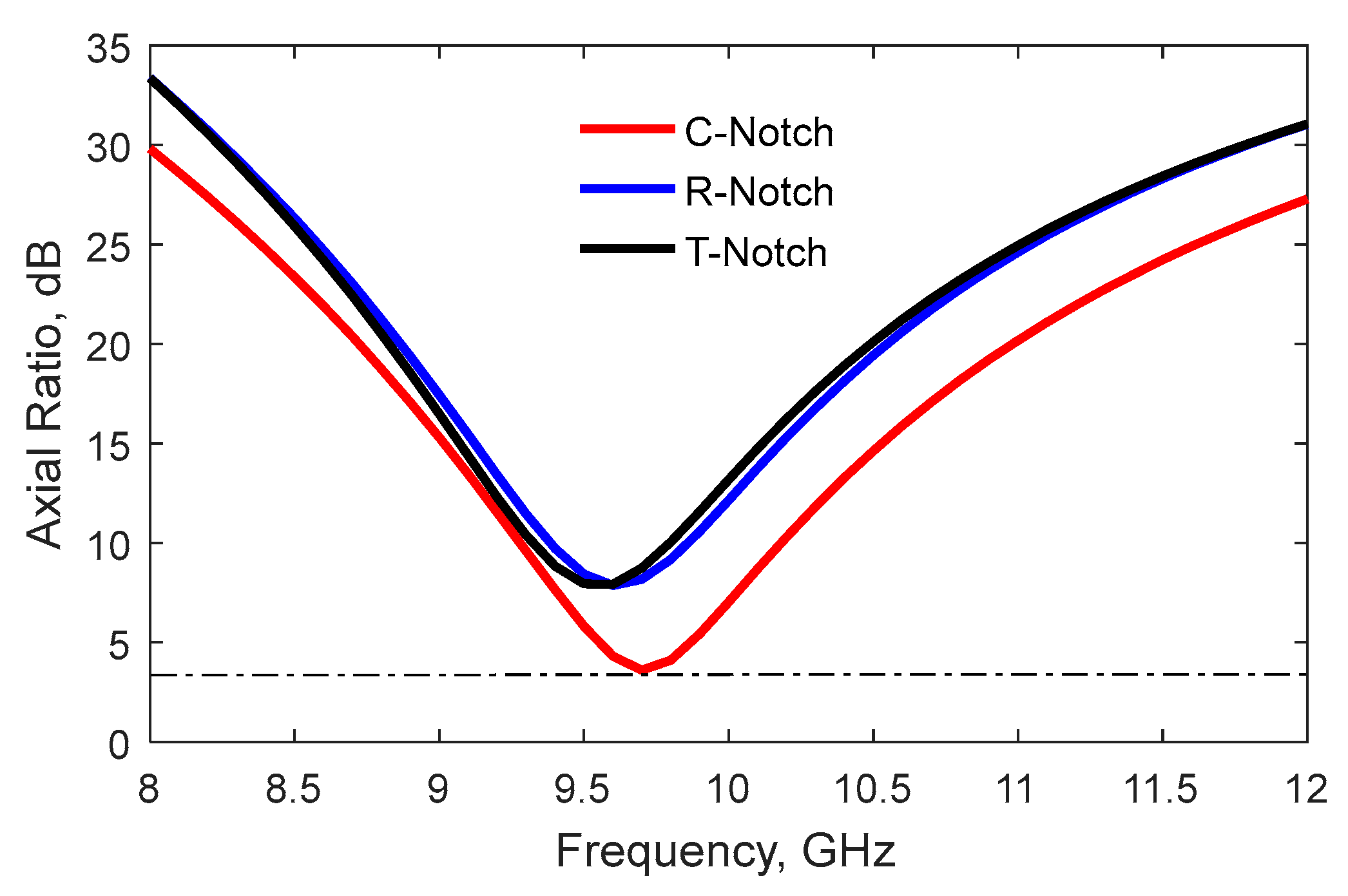
Figure 8.
UCs under test; (a) Cell #1 - (b) Cell #2
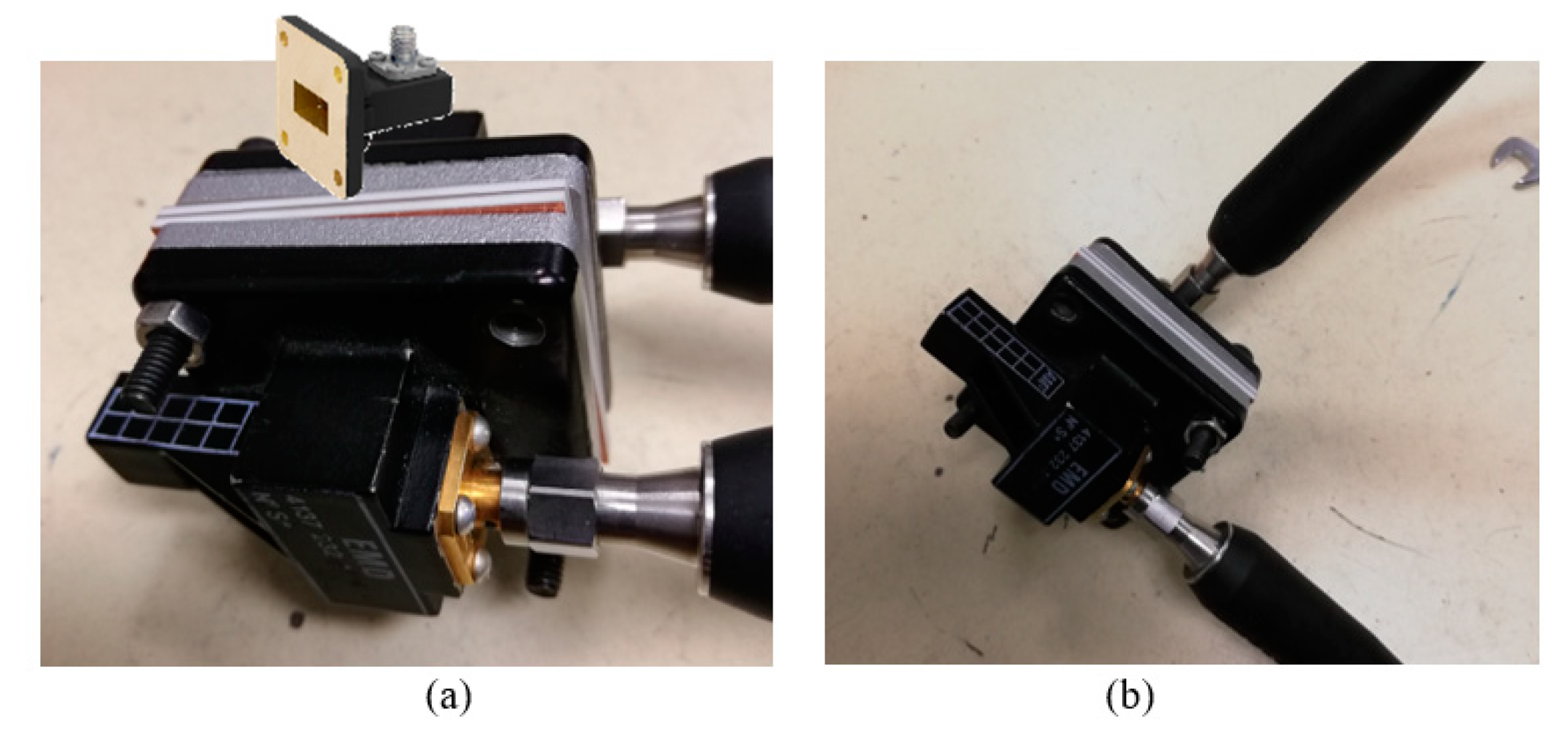
Figure 9.
The S-parameters of the UC.
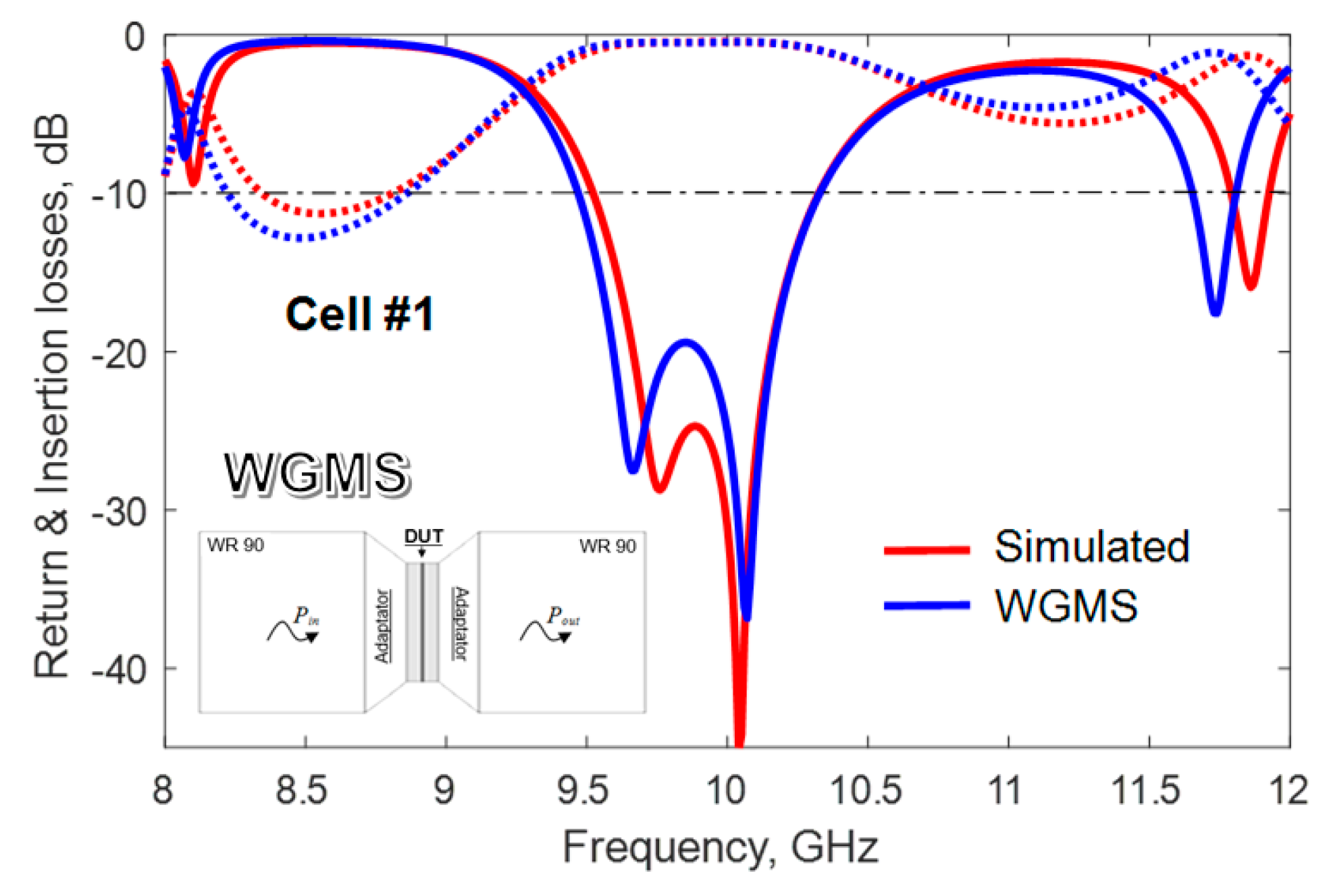
Figure 10.
196-Element TA prototype; Focal source, Mechanical support and antenna array.
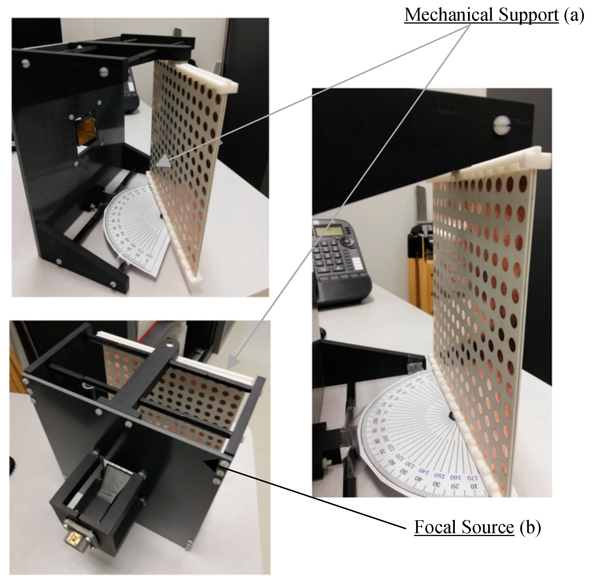
Figure 11.
Variation of the radiation and aperture efficiencies.
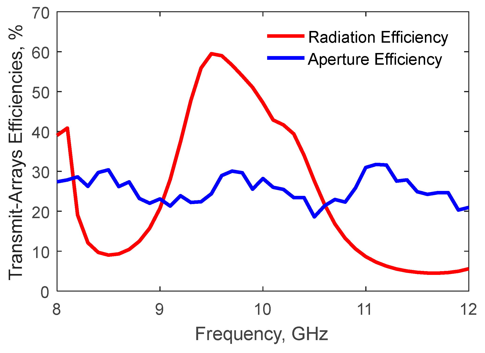
Figure 12.
Variation of the directivity and gain.
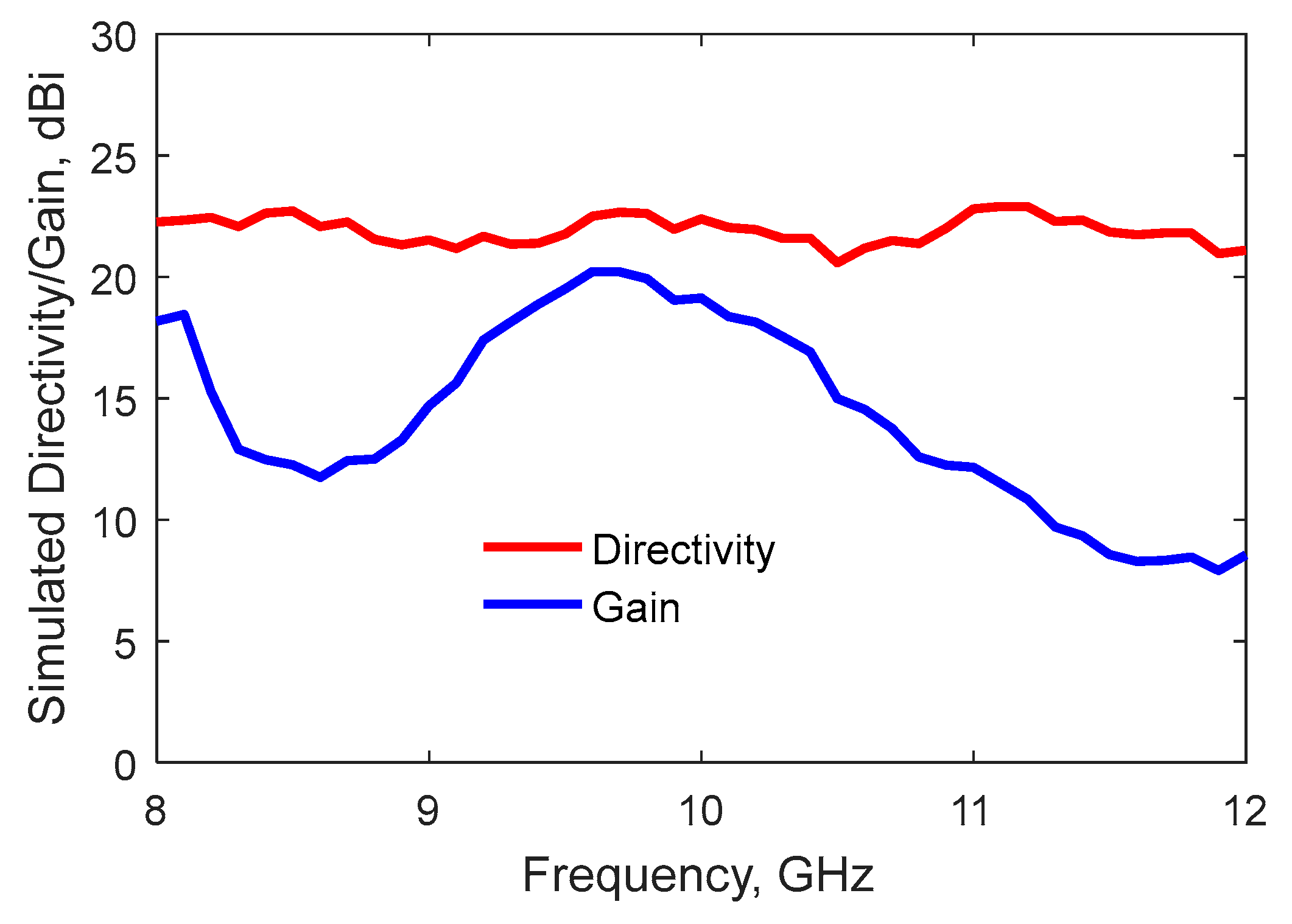
Figure 13.
Radiation pattern of the linearly-polarized TAA with 1-bit quantization computed at 10 GHz.
Figure 13.
Radiation pattern of the linearly-polarized TAA with 1-bit quantization computed at 10 GHz.
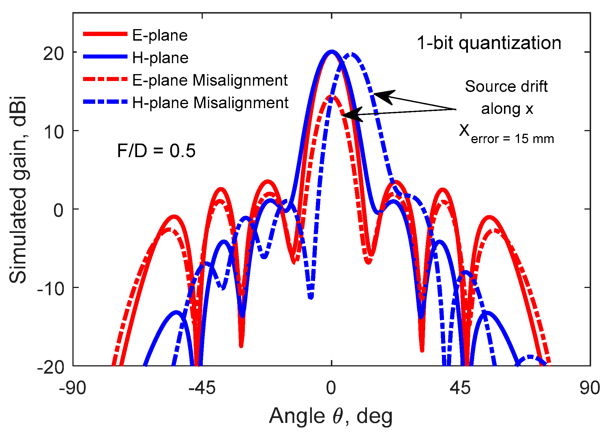
Figure 14.
Radiation pattern of the linearly-polarized TAA computed at 10 GHz: Perfect and 1-bit phase quantization.
Figure 14.
Radiation pattern of the linearly-polarized TAA computed at 10 GHz: Perfect and 1-bit phase quantization.
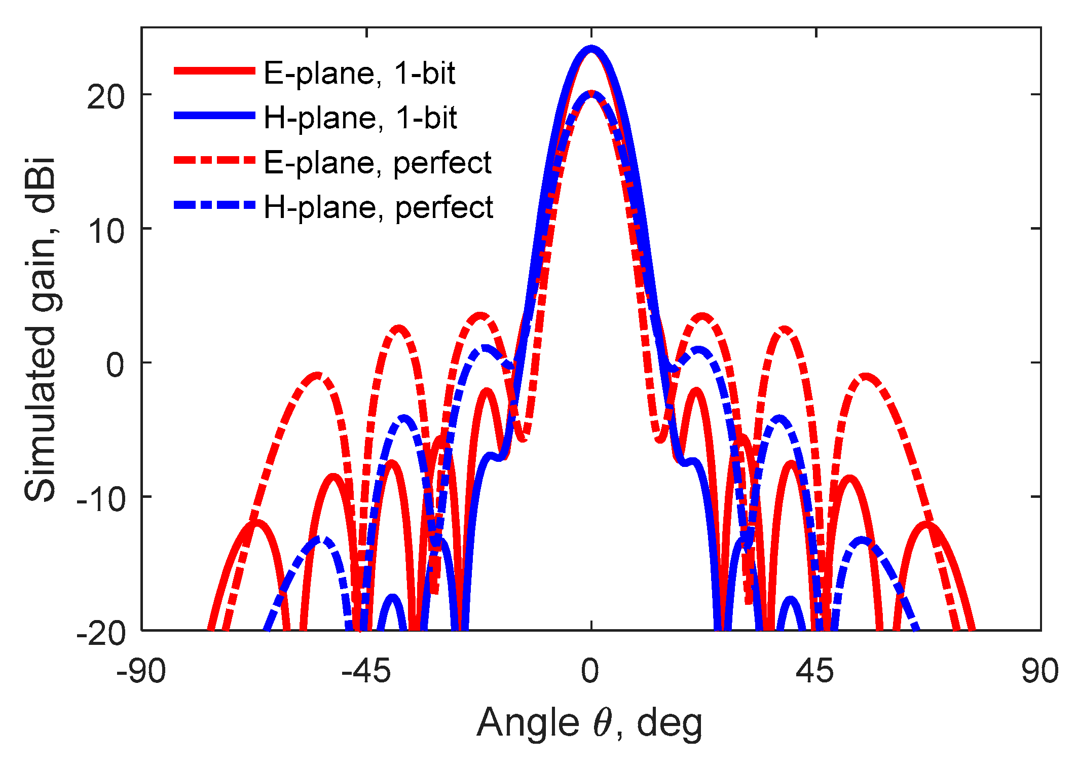
Figure 15.
Beam-scanning capability for passive TAA; Comparison between translation and tilting source method.
Figure 15.
Beam-scanning capability for passive TAA; Comparison between translation and tilting source method.
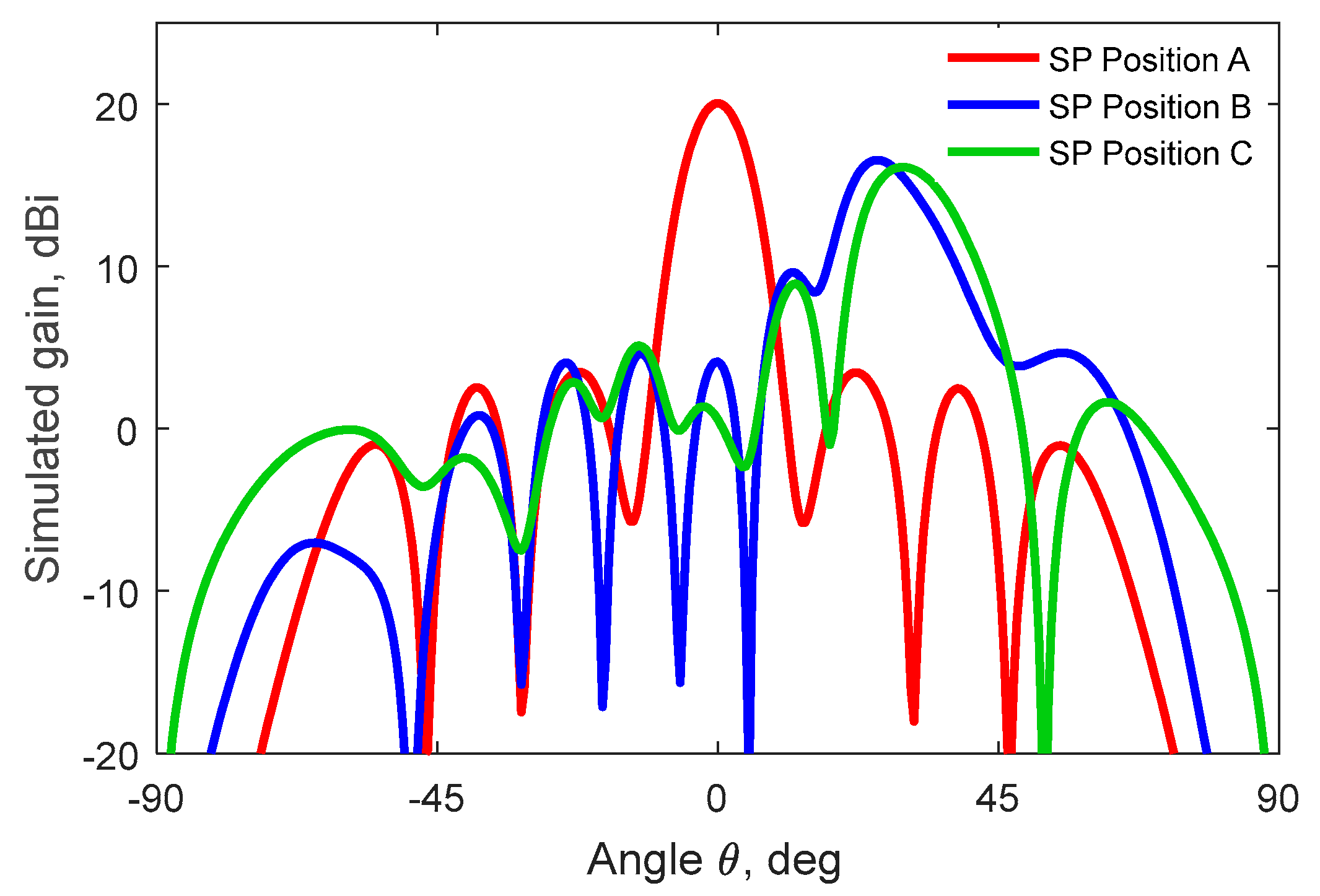
Figure 16.
Measurement setup of the TA prototype in the anechoic chamber of LAPLACE.

Figure 17.
Measured radiation patterns of the TA prototype performed at 10 GHz.
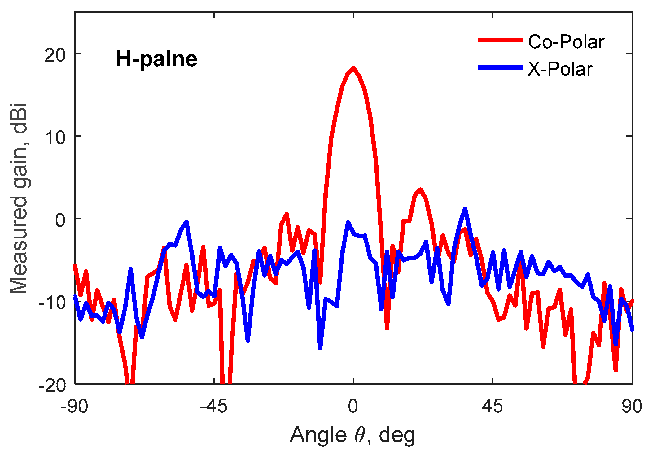
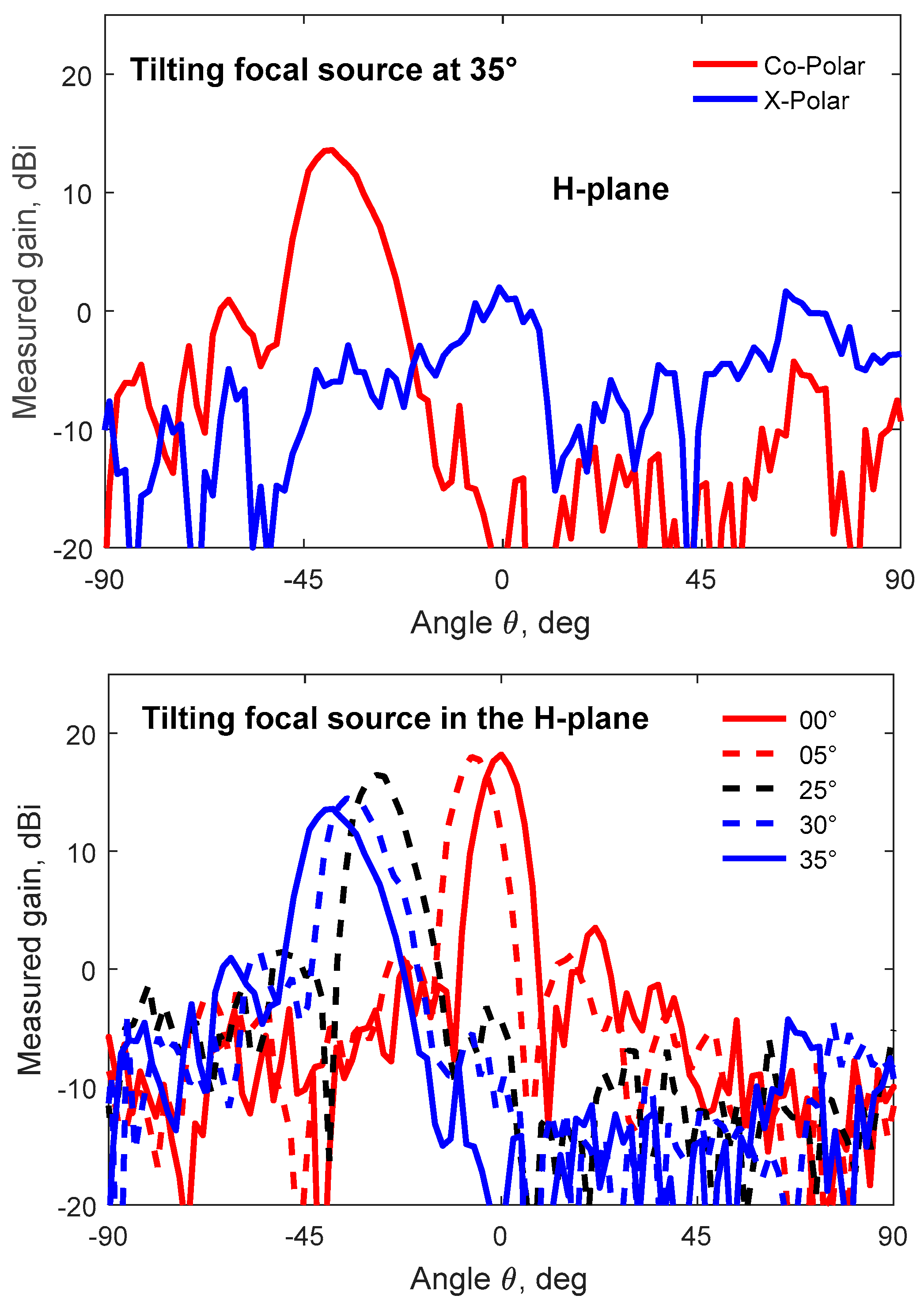

Table 1.
Impact of the phase correction on the TAA performances.
| Phase correction | 0-bit | 1-bit | 2-bit | 3-bit | N-bit |
|---|---|---|---|---|---|
| Directivity (dBi) | 12.6 | 22.4 | 25 | 25.6 | 25.8 |
| Gain (dBi) | 10.3 | 20.1 | 22.7 | 23.2 | 23.4 |
| Quantization loss (dB) | 13.2 | 3.4 | 0.8 | 0.2 | 0 |
Table 2.
Impact of the focal distance on the TAA radiation performances.
| F (mm) | 75 | 90 | 105 | 130 | 150 | 180 | 210 | 250 |
|---|---|---|---|---|---|---|---|---|
| Spill-over loss (dB) | 1.92 | 2 | 2.08 | 2.26 | 2.49 | 2.84 | 3.31 | 3.98 |
| Quantization loss (dB) | 4.06 | 3.67 | 3.36 | 3.28 | 3.58 | 3.69 | 3.9 | 3.14 |
| Taper loss (dB) | 2.94 | 2.83 | 2.14 | 1.32 | 0.92 | 0.61 | 0.5 | 0.26 |
| Insertion loss (dB) | 0.26 | 0.26 | 0.26 | 0.26 | 0.26 | 0.26 | 0.26 | 0.26 |
| Directivity (dBi) | 20.9 | 21.4 | 22.4 | 23.3 | 23.4 | 23.6 | 23.5 | 24.5 |
| Gain (dBi) | 18.7 | 19.1 | 20.1 | 20.7 | 20.6 | 20.5 | 20 | 20.3 |
| SLL H-plane (dB) | 17.7 | 18.9 | 16.6 | 14.7 | 17.7 | 16.4 | 16.2 | 13.5 |
| Aperture Efficiency (%) | 20 | 22.4 | 28.2 | 34.7 | 35.5 | 37.2 | 36.3 | 45.7 |
| Radiation Efficiency (%) | 60.4 | 59.3 | 58.3 | 55.9 | 53.1 | 48.9 | 43.9 | 37.6 |
Disclaimer/Publisher’s Note: The statements, opinions and data contained in all publications are solely those of the individual author(s) and contributor(s) and not of MDPI and/or the editor(s). MDPI and/or the editor(s) disclaim responsibility for any injury to people or property resulting from any ideas, methods, instructions or products referred to in the content. |
© 2024 by the authors. Licensee MDPI, Basel, Switzerland. This article is an open access article distributed under the terms and conditions of the Creative Commons Attribution (CC BY) license (http://creativecommons.org/licenses/by/4.0/).
Copyright: This open access article is published under a Creative Commons CC BY 4.0 license, which permit the free download, distribution, and reuse, provided that the author and preprint are cited in any reuse.


