

Submitted:
29 June 2024
Posted:
02 July 2024
You are already at the latest version
Abstract
This study aims to develop low-cost, eco-friendly and circular economy-compliant composite materials by creating three types of magnetorheological suspensions (MRSs) utilizing lard, carbonyl iron (CI) microparticles, and varying quantities of gelatin particles (GP). These MRSs serve as dielectric materials in cylindrical cells used to fabricate electric capacitors. The equivalent electrical capacitance (C) of these capacitors is measured under different magnetic flux densities (B≤160 mT) superimposed on a medium-frequency electric field (f = 1 kHz) over a period of 120 seconds. The results indicate that at high values of B, by increasing the GP content to 20 vol.% decreases the capacitance C up to about one order of magnitude compared to MRS without GP. From the measured data, the average values of capacitance Cm are derived, enabling the calculation of relative dielectric permittivities (ϵr′) and the dynamic viscosities (η) of the MRSs. It is demonstrated that ϵr′ and η can be adjusted by modifying the MRS composition and fine-tuned through the magnetic flux density B. A theoretical model based on the theory of dipolar approximations is used to show that ϵr′, η and the magnetodielectric effect can be coarsely adjusted through the composition of MRSs and finely adjusted through the values B of the magnetic flux density. The ability to fine-tune these properties highlights the versatility of these materials, making them suitable for applications in various industries, including electronics, automotive and aerospace.
Keywords:
lard
; gelatine
; carbonyl iron microparticles
; viscosity
; relative dielectric permittivity
; dielectric loss factor
; magnetodielectric effect
1. Introduction
Magnetorheological suspensions (MRSs) consist of a liquid matrix in which magnetizable microparticles and additives are dispersed [1,2,3,4,5,6]. When exposed to a magnetic field [1,2,3], the magnetizable microparticles transform into magnetic dipoles. These dipoles interact, forming aggregates in the shape of columns. The strength of these columns is determined by the magnetic flux density and the magnetic properties of the magnetizable phase [2]. The formation of these aggregates results in significant changes to the viscosity [1], electrical conductivity [7], and dielectric properties [4] of MRSs. These effects are beneficial for applications in artificial intelligence [5], vibration dampers [6], clutches [8] or passive electrical circuit elements [7].
Traditionally, MRSs often utilize synthetic oils, such as paraffin, as liquid matrix and high-purity additives, which can be expensive and environmentally harmful [9,10,11]. Synthetic oils and certain polymeric additives do not decompose easily, contributing to long-term environmental pollution. This may hamper a widespread adoption of MRS technology, particularly in cost-sensitive applications. Therefore, in the last years, preparation of MRSs with environmentally friendly and recyclable components is an active research area [1,12,13,14,15]. These includes MRSs based on honey with carbonyl iron (CI) microparticles [16] and turmeric powder [12], composites based on honey with CI microparticles and beeswax [13] or MRSs based on nanocellulose [1], nanolignocelluloses [14] and gelatine-coated CI microparticles [15].
An essential requirement for MRSs is the ability to precisely control their viscosity. This is a key feature for their application in devices such as dampers and clutches [17,18]. However, achieving stable and tunable viscosity in eco-friendly and low-cost MRSs remains a challenge. The dielectric properties of MRSs, such as relative dielectric permittivity and dielectric loss factor, are also critical for applications in capacitors and other electronic components [19,20]. Ensuring that these properties can be finely tuned and remain stable under varying operational conditions is a significant challenge. In addition, sedimentation of magnetizable particles is a common issue that affects the long-term stability and performance of the suspension [10,21,22]. Particles tend to settle over time due to gravity, leading to a non-uniform distribution and inconsistent magnetic and rheological properties.
By addressing the challenges of cost, environmental impact, viscosity control, dielectric properties and sedimentation, the present work utilizes lard [23,24], animal gelatin particles (GP; [25]), and CI microparticles to develop a sustainable alternative for traditional MRS. Lard is a promising candidate due to its cost-effectiveness, biodegradability, and renewability. Lard’s high viscosity at room temperature helps in preventing the sedimentation of GP and CI microparticles. This ensures a more uniform distribution of particles, maintaining consistent magnetic and rheological properties over time. It is used in the production of biodiesel-type fuels [26], antioxidants [27], has beneficial effects on the intestinal microbiome[28], and can be processed into glycerides and hydrogenated glycerides for cosmetic products [29]. Animal gelatin, a fibrous protein derived from the tissues of pigs and cattle [30], finds applications across various industries, including food, pharmaceuticals, and tissue regeneration. Its ability to mold easily and form films with micrometric dimensions makes it suitable for use in MRSs.
This study aims to demonstrate that suspensions based on lard, GP and CI microparticles exhibit dielectric and magnetodielectric properties similar to those of traditional MRSs [1,2,3,4,5,6]. Thus, the suspensions are used as dielectric materials in cylindrical cells for the fabrication of electric capacitors. The electrical capacitance and resistance of these capacitors are measured under different magnetic flux densities (from 0 to 160 mT) and a medium-frequency electric field (1 kHz) over a period of 120 s. Further, using the model of dipolar approximation [31,32,33,34], the dynamic viscosity, relative dielectric permittivity, and magnetodielectric effect are investigated as a function of magnetic flux density and the ratio of the volume fraction of lard to GP. This model allows adjustments through the composition of the MRSs and variations in the magnetic flux density, by considering the interactions of magnetic dipoles within the suspensions.
To address these issues, this paper is organized as follows: Section 2 details the materials and methods used in the preparation of the MRSs, including the specific procedures for measuring the bulk densities, dielectric permittivity, and other key properties of the components. Section 3 describes the fabrication process of cylindrical electric capacitors (CECs) utilizing the prepared MRSs as dielectric materials. In Section 4, we present the experimental setup and the methodology for measuring the electrical properties of the CECs under various magnetic flux densities. Section 5 discusses the results of these measurements, focusing on the stability and performance of the CECs with different compositions of lard, GP and CI microparticles. Section 5 provides a detailed discussion of the findings in the context of existing literature and theoretical models, highlighting the implications and potential applications of the developed MRSs. Finally, Section 7 concludes the paper by summarizing the key contributions and suggesting directions for future research.
2. Preparation of MRSs
2.1. Materials
The materials used for producing MRS are as follows:
- Lard, produced by Elit (Alba Iulia, Romania), supplied through commercial stores.
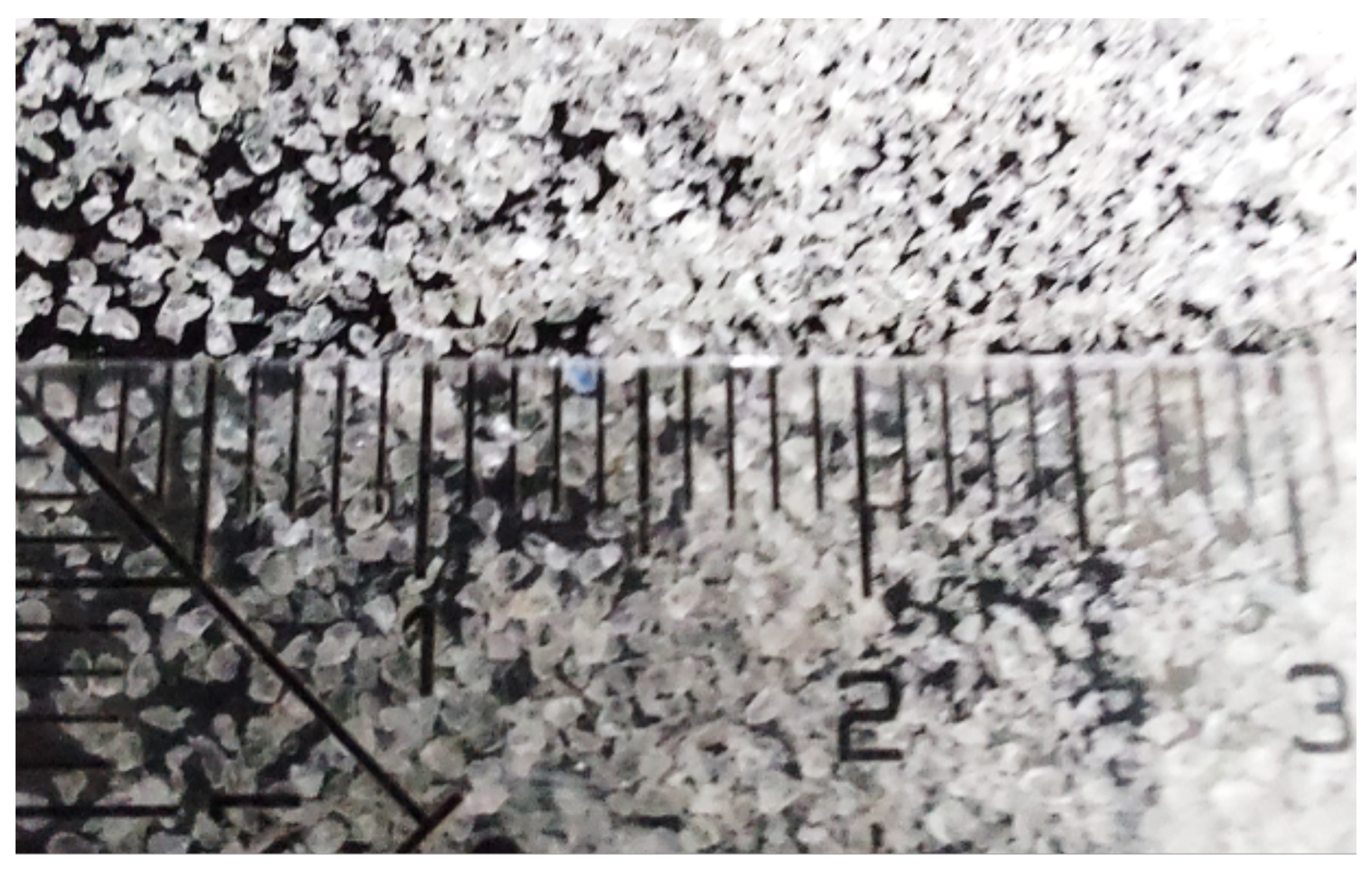
- Animal gelatin, from Dr. Oetker SRL (Curtea de Arges, Romania), supplied through grocery stores. The gelatin is in the form of white granules (GP) with equivalent diameters less than or equal to 1 mm (Figure A1 in Appendix A).
- CI microparticles, are produced by Sigma-Aldrich (St. Louis, USA). Their sizes are between 4.5 m and 5.4 m.
For each material, the bulk density is measured using the graduated cylinder method at a temperature of 25C. This is a common laboratory technique used to measure the volume and, in combination with other measurements, the density of liquids and granular materials. In our case we used a graduated cylinder, i.e. a cylindrical container with markings (gradations) along its length, used to measure liquid volumes with high precision, an analytical balance, used to measure mass with high-precision, and the sample material, i.e. component whose density is to be determined. The relative dielectric permittivity () and dielectric loss factor () are measured a frequency of kHz. The values of measured bulk densities (), and , are listed in Table 1.
2.2. Method
The manufacturing of MRS suspensions is carried out through the following steps:
- The volume of lard, of CI microparticles and of GP are measured. The corresponding values are listed in Table 2.
- In a Berzelius beaker, the volumes and corresponding to MRS from Table 2 are introduced. The components, consisting of lard and CI microparticles, are mixed while heating (approximately at 250C) for about five minutes. The mixing continues until the liquid mixture reaches ambient temperature (approximately 27C). At the end of this stage, a dark-colored mixture, hereafter referred to as MRS suspension, is obtained.
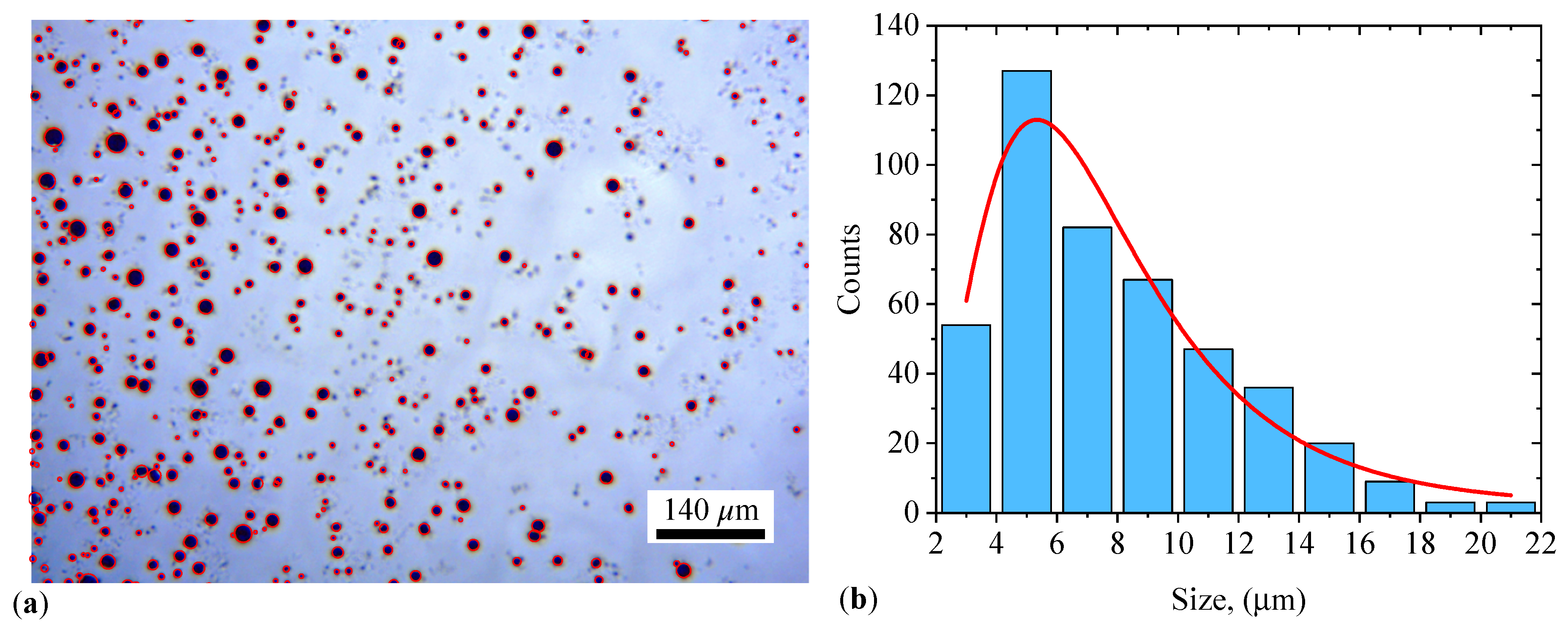
- Volumes of 3.2 cm of lard and 0.4 cm of GP are measured and introduced into a Berzelius beaker. In a second Berzelius beaker, are introduced 2.8 cm of lard and 0.8 cm of GP. The mixtures in the Berzelius beakers are homogenized by turn at a temperature of approximately 250C for about five minutes, after which the mixing continues until the liquid mixtures reach ambient temperature (approximately 27C). A film of the prepared mixture is deposited on a glass slide. The resulting image is shown in Figure 1(a). It can be observed from this figure that the formed microparticles have micrometric dimensions with an average diameter of 6.94 ± 0.55 m (see Appendix B for details), and have a spherical shape.
- In the Berzelius beaker with 3.2 cm of lard and 0.4 cm of GP, are introduced 0.4 cm of CI microparticles and the mixture is heated to approximately 150C for about five minutes. At the end of this period, the mixture is further homogenized until it reaches ambient temperature. At the end of this stage, the MRS suspension is formed.
- In the Berzelius beaker with 2.8 cm of lard and 0.8 cm of GP, is introduced 0.4 cm of CI microparticles and the mixture is heated to approximately 150C for about five minutes. At the end of this period, the mixture further homogenizing until it reaches ambient temperature. At the end of this stage, the MRS suspension is formed.
The MRSs suspensions thus prepared have volume fractions , , and with values specified in Table 2. In the study of the magnetic properties of composite materials, the relationship is used to determine their specific saturation magnetization , where is the magnetic constant of the vacuum, is the volume fraction of CI microparticles, and is the specific saturation magnetization of the CI microparticles. For Am/kg [31] and vol.% introduced into the specified relation, the value Am/kg is obtained. A film of the MRS suspension is visualized using an Optika microscope. Upon applying a magnetic field (Figure 1b), the CI microparticles form chains of magnetic dipoles along the direction of , through the field formed by the GP and lard microparticles.
3. Fabrication of CECs
3.1. Materials
The materials needed for manufacturing CECs are:
- Laminated board (LB) based on epoxy resin, reinforced with fiberglass, with one side plated with copper, having a thickness of 0.35 m. The LB is obtained from HobbyMarket (Romania) and is delivered in dimensions of 210 mm × 100 mm × 1.5 mm.
- Non-slip rubber pad (RP), type CAR-BOY (made in Japan) and supplied by Hornbach (Romania). The RP pad has a diameter of 40 mm and a thickness of 2 mm.
- Surgical adhesive tape Durapore (ST), manufactured by 3M EMEA GmbH (Switzerland), and supplied through Help Net (Romania). The tape is 5 cm wide and 9 m long.
3.2. Method
The main steps in preparing CECs are:
- LB is cut into six pieces. Each piece has dimensions of 30 mm× 30 mm× 1.5 mm.
- Three rings with an inner diameter of 20 mm are cut from the RP pad.
- On top of the MC filled with MRS (Figure 2b), the copper-coated side of the LB is fixed by pressing. The assembly thus realized is consolidated with ST tape. At the end of this stage, three capacitors denoted by CEC, CEC and CEC are obtained, as shown in Figure 3 (see details in Figure A3 in Appendix C).
The experimental setup for studying MRSs has the overall configuration shown in Figure 4. The setup includes an in-house built electromagnet composed of a magnetic yoke (position 1) and a coil (position 2) connected to the DCS source. Between the magnetic poles N and S, the CEC capacitor and the Hall probe (h) of the gaussmeter (Gs) are mechanically fixed via the non-magnetic axis (position 3). The CEC capacitors are connected to the RLC bridge (Br).
By adjusting the current intensity I through the coil up to a maximum of 5 A, the magnetic flux density B between the magnetic poles N and S can be continuously adjusted up to a maximum of 400 mT. The DCS source, model RXN-3020D, is from Shenzhen Ever Good Electronic Co., Ltd. (China). The B values of the magnetic flux density are measured with the gaussmeter Gs type DX-102 and the Hall probe h. The gaussmeter and Hall probe h are from Dexing-Magnetic Industrial Park (China). The RLC bridge (Br; Taiwan) is of type CHY 41R. During measurements, the bridge is connected in parallel mode and at a frequency of kHz.
4. Measurements of Electrical Properties
Between the N and S poles of the electromagnet in Figure 4, we introduce by tyrn the capacitors CEC, CEC and CEC, along with the Hall probe h, securing them mechanically. The capacitors, are subjected to a mechanical pressure of approximately , applied by an lead mass. Each capacitor is electrically connected to the RLC bridge, set on the C mode for measuring electrical capacitance. The ambient temperature is . Through the RS232C interface of the RLC bridge, the capacitance values measured in the magnetic field, at the initial moment ( s) and at s, are recorded by a computing unit, not shown in Figure 4. During the measurements, the B values of the magnetic flux density are increased in steps of 10 mT, up to a maximum of 160 mT.
5. Results
5.1. Stability of CECs with Lard, GP and Respectively CI Microparticles
The time dependence of the equivalent electrical capacitance C and resistance R for CECs with lard, GP, and respectively CI microparticles are shown in Figure 5(a) and (b). The results show that both C and R depend on the type of the dielectric material used in CEC. Their behaviour is quasi-constant with time t (see Appendix D for details) and thus C and R are stable during measurements. This behaviour leads to average values of and close to those of C and R (see Table A1 in Appendix D).
The equivalent electrical resistance values R from Figure 5(b) and implicitly the average equivalent electrical resistances are the effect of contact resistances between CI microparticles. This phenomenon is confirmed in Refs. [35,36] for the case of microparticles composed of polypyrrole nanotubes decorated with magnetite nanoparticles and in Ref. [37] for the case of nickel microparticles coated with polypyrrole. These studies show that increasing the compression voltage decreases the resistance of the body formed by the microparticles. On the other hand, the electrical capacitance C and the average capacitance result from the formation of series and parallel microcapacitors [13] in the space occupied by the CI microparticles. The electrical conduction of lard is due to the presence of fatty acids (palmitic acid, stearic acid, oleic acid, and linoleic acid) and triglycerides [24]. The ratio of these components affects their dielectric properties [38]. The electrical conduction of the body formed by GP is due to contact resistance between the particles. Conversely, the intrinsic electrical conduction of GP and their dielectric properties is due to the presence of amino acids [39].
5.2. Electrical Properties of CECs
For CECs with MRS as dielectric material, the recorded data are graphically represented in Figure 6(a). The average values, , of the capacitance are shown in Figure 6(b). These are obtained from the capacitance values recorded at s and s, corresponding to the B values of the magnetic flux density in Figure 6(a). The experimental points are well approximated by the Equation (A1) in Appendix D.
From Figure 6(a) and (b), it is observed that the values of and of for capacitors ( and 3) depend on the presence of the magnetic field and the presence of GP. In the absence of a magnetic field, the capacitances at mT depend on the volume fraction GP. They decrease by about half for the capacitor with (i.e. CEC) and by about 2.5 times for the capacitor with (i.e. CEC). These results are in agreement with Equation (A23) in Appendix F. This equation, corroborated with Equation (A9) shows that by increasing the values of the distance (for and 3) between the mass centers of the CI microparticles results in a decrease in the values of , in agreement with the experimental data in Figure 6.
In the presence of a magnetic field, the values of (for and 3) increase significantly with the increase in the values of B of the magnetic flux density, in agreement with Equation (A23) in Appendix F. This effect is due to the fact that during the time t of applying the value B of the magnetic flux density, the ratio in Equation (A23) is always subunitary and remains constant. This is possible by increasing the value of of the viscosity of with the increase in the value of B of the magnetic flux density, as will be shown later. The calculation relation of the viscosity of the suspensions in the magnetic field is obtained from Appendix F.
Thus, from Equations (A25), (A26) and (A27), where we set , we obtain the viscosity expressions for the MRS suspensions, namely:
The functions from Figure 6, corresponding to and 3, are introduced in Equations (1), (2) and respectively in (3). At the end of this step, in Figure 7(a), we obtain the functions (for ). It can be observed from Figure 7(a) that the viscosity of the suspensions in a magnetic field is significantly influenced by the magnetic field, similar to the case of classical MRSs [40] and in agreement with the model developed in Appendix F (Equations (A25), (A26) and (A27)). From the same figure, it is also noted that for the same values of B, the viscosity is influenced by the volume fraction of GP. By considering as the coupling factor between shear stress and shear rate, then the results obtained in Figure 7(a) are similar to those obtained in Ref. [40], where in a hybrid MRS the coupling coefficient between cotton microfibers increases with the increase in B and the amount of CI microparticles.
The relative dielectric permittivity is calculated using Equation (A4) from Appendix E. In this expression, we introduce the functions , for , from Figure 6(b), and we obtain in Figure 7(b) the functions . It can be observed from this figure that the values of for the MRSs increase significantly with the increase in B magnetic flux density, similar to classical MRSs [31]. However, the GP creates layers within the compositional structure of the , for suspensions between the lines of magnetic dipoles (CI microparticles). The resulting effect is the creation of capacitors connected in series between the copper foils of the in the absence and presence of the magnetic field. The distance between the plates of these capacitors increases with the increase in the value of , as suggested by the results in Figure 6(a) and Figure 6(b) for the capacitors for .
We define the magnetodielectric effect using the expression:
The functions for Figure 5(b) are substituted into Equation (4) yielding the functions as shown in Figure 8. The results show that the magnetodielectric effect of the suspensions (for ) is significantly influenced by the magnitude of the B magnetic flux density. This effect is also seen in classical MRS suspensions [13]. The introduction of gelatin decreases the MDE magnitude as the value increases. For at , the MDE is approximately 14.39. However, at the same B value, the MDE magnitude decreases by approximately 2.3 times for (see Figure 8b). This effect is due to the increased initial distance between CI microparticles as a result of the increased value (see Appendix F, Equation (A8) in conjunction with Equations (A23) and (A24)).
6. Discussion
The results obtained from the experimental investigation of MRSs composed of lard, GP and CI microparticles have demonstrated several noteworthy findings. These findings contribute to the broader context of existing literature on MRSs and their applications.
The stability of CECs using these MRSs was confirmed through time-dependent measurements of capacitance C and resistance R (Figure 5). The quasi-constant behavior of these properties over time indicates that the suspensions maintain their performance characteristics under operational conditions, which is critical for practical applications in electronics and other industries.
The dynamic viscosity (Figure 7a) and relative dielectric permittivity (Figure 7b) of the suspensions were found to be dependent on both B and . As B increased, both and exhibited significant increases, a phenomenon similarly observed in traditional MRSs. The presence of GP, however, introduced an additional layer of complexity, acting as dielectric barriers and modifying the capacitance and resistance within the suspensions. This dual role of GP as both a structural and functional component underscores its importance in fine-tuning the properties of MRSs.
The magnetodielectric effect MDE (Figure 8) observed in the suspensions also varied significantly with B and . Specifically, the MDE was shown to decrease with increasing , which is attributed to the increased initial distance between CI microparticles, thereby reducing magnetic interactions. This is consistent with the theoretical models based on the dipolar approximation and previous studies that highlight the role of particle distribution in MRS behavior [19].
The implications of this study are manifold, suggesting several avenues for future research. Further refinement of the ratios and types of biodegradable materials could enhance the performance and stability of MRSs, making them suitable for a wider range of applications. Investigating the long-term stability and performance of these suspensions under varying environmental conditions would provide deeper insights into their practical viability. Exploring the use of these MRSs in advanced technological applications, such as smart materials for adaptive systems or in medical devices, could open new frontiers for research and development. Enhancing the theoretical models to better predict the behavior of such complex suspensions under different operational scenarios could lead to more accurate and reliable designs of MRS-based devices.
These findings extend the work of prior research in several key areas. Previous studies have explored various biodegradable and renewable materials for MRSs, such as nanocellulose [1] and honey [12]. The use of lard and gelatin in this study adds to the growing body of literature on sustainable alternatives, emphasizing the potential for low-cost and environmentally MRSs. The observed MDEs are consistent with those reported in MRSs based on magnetorheological bio-suspensions [4]. The ability to achieve similar effects with other sustainable materials highlights the versatility and adaptability of the developed suspensions. Controlling the viscosity of MRSs is crucial for their application in devices like dampers and clutches. The results (Figure 7a) align with studies that have shown the impact of magnetic fields on viscosity, further validating the use of MRSs in mechanical and automotive applications [17,18].
7. Conclusions
This study successfully demonstrates the preparation and characterization of MRSs using lard, GP and CI microparticles. The findings indicate that these low-cost and eco-friendly materials can effectively replace traditional synthetic materials in MRSs, offering similar magnetodielectric and rheological properties. The constructed cylindrical capacitors showed significant increases in dynamic viscosity and relative dielectric permittivity with increasing magnetic flux density and decreases with increasing gelatin volume fraction. These effects are consistent with those observed in conventional MRSs, suggesting that the newly developed suspensions can be viable substitutes in various applications.
The experimental results highlight the critical role of the magnetic field in influencing the properties of the suspensions, validating their potential use in mechanical and automotive applications where viscosity control is essential. The study also underscores the dual role of gelatin as both a structural and functional component, enhancing the fine-tuning capabilities of MRS properties. The observed magnetodielectric effect and its dependence on the volume fraction of gelatin and magnetic flux density align with theoretical models, providing a robust foundation for further research and development.
Overall, this study contributes significantly to the field of magnetorheological materials, presenting a sustainable alternative that aligns with the principles of circular economy and environmental stewardship. The promising results pave the way for future innovations and applications in various industrial and technological domains.
Author Contributions
Conceptualization, I.B. and E.M.A.; methodology, I.B. and E.M.A; validation, M.B., I.B. and E.M.A.; formal analysis, M.B., I.B. and E.M.A.; investigation, I.B. and E.M.A.; writing—original draft preparation, I.B. and E.M.A.; writing—review and editing, M.B., I.B., E.M.A. and L.M.E.C; visualization, E.M.A.; supervision, I.B.; All authors have read and agreed to the published version of the manuscript.
Funding
This research received no external funding.
Institutional Review Board Statement
Not applicable.
Informed Consent Statement
Not applicable.
Data Availability Statement
The original contributions presented in the study are included in the article/supplementary material, further inquiries can be directed to the corresponding author/s.
Appendix A. Morphology of Gelatin Particles GP
Gelatin, in bulk form (Figure A1), has a white color. The particles have irregular shapes and equivalent diameters, most of which do not exceed 1 mm.
Figure A1.
Photo of bulk gelatin used to obtain gelatin particles GP. Units are in cm.
Appendix B. Size Distribution of GP
The average diameter of GP is 6.94 ± 0.55 m and it has been determined from a set of 448 particles, marked in red circles in Figure A2(a). To this aim a log-normal fit has been used on the size distribution (see Figure A2b).
Figure A2.
(a) Photo of GMs as shown in Figure 1(a) but with marked particles (red disks) for which the size distribution has been calculated. (b) The corresponding size distribution and a fit (red curve) with a log-normal function.
Figure A2.
(a) Photo of GMs as shown in Figure 1(a) but with marked particles (red disks) for which the size distribution has been calculated. (b) The corresponding size distribution and a fit (red curve) with a log-normal function.
Appendix C. CECs with Lard, CP and GP Microparticles
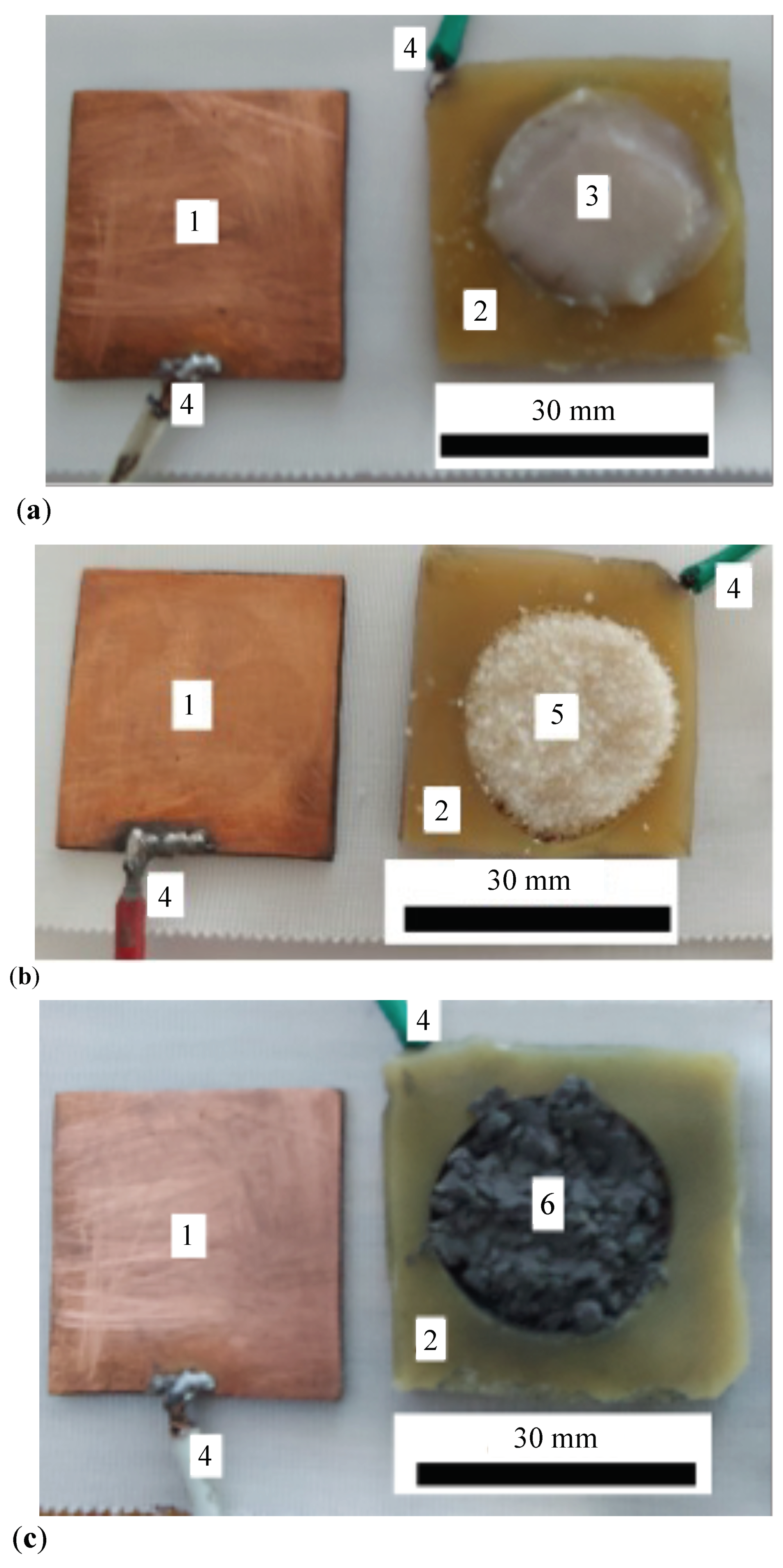
The lard, gelatin and CI microparticles are introduced into measurement cells, as shown in Figure A3. By consolidating with adhesive tape, capacitors of the type shown in Figure 3 are obtained.
Figure A3.
Measuring cells with lard (a), GP (b) and CI microparticles (c). 1 - copper electrode, 2 - insulating ring with a diameter of 20 mm and thickness of 2 mm, 3 - lard, 4 - copper conductor, 5 - GP, 6 - CI microparticles.
Figure A3.
Measuring cells with lard (a), GP (b) and CI microparticles (c). 1 - copper electrode, 2 - insulating ring with a diameter of 20 mm and thickness of 2 mm, 3 - lard, 4 - copper conductor, 5 - GP, 6 - CI microparticles.
Appendix D. Fitting C and R Data for CECs with Lard, CP and GP Microparticles
The dependence of the quantities C and R on time t in Figure 5 is given by the following equations:
and respectively,
Here, and are the values of the capacitance and electrical resistance at s, respectively; is the slope of function given in Equation (A1) and is the slope of function in Equation (A2). The values of and and the corresponding slopes and are extracted from Figure 5 and are presented in Table A1.

Table A1.
Values of the parameters , and obtained by fitting data in Figure 5 with Equations (A1), and respectively (A2).
| (pF) | (pF/s) | (k) | (k/s) | |
|---|---|---|---|---|
| Lard | 17.9 ± 1.91 × 10 | 4.762 × 10 ± 2.75 × 10 | 275 ± 0.238 | 0.0407 ± 0.0343 |
| GP | 16.3 ± 5.73 × 10 | 1.429 × 10 ± 8.25 × 10 | 438 ± 0.344 | 0.0361 ± 0.0496 |
| CI | 27.9 ± 5.73 × 10 | 1.429 × 10 ± 8.25 × 10 | 892 ± 0.168 | 0.0169 ± 0.0343 |
Appendix E. Fitting C and C m Data for CECs with MRSs
The experimental data in Figure 6(a) are fitted by polynomials of the form:
in which and are the electrical capacitances of the capacitors in the presence and absence of a magnetic field with magnetic flux density B, and is a dimensionless parameter whose magnitude depends on the composition of . The values of and corresponding to the capacitors are listed in Table A2 for , and respectively for . Due to very small errors, the average values of the capacitance essentially coincide with .
From an electrical point of view, CECs consist of a plane capacitor connected in parallel with a linear resistor . Given the formula for calculating the electric capacity of a planar capacitor and, respectively, the formula of a linear resistor, we obtain the relative dielectric permittivity and the dielectric loss coefficient of the dielectric materials between the electrodes of the CECs, as follows:
and respectively
where D and are the diameter and thickness of the dielectric materials in the CEC capacitors; is the vacuum permittivity constant; and f is the frequency of the alternating electric field.
Appendix F. Derivation of the Relation for Calculating the Capacitance of CECs
For the obtained CECs (see Figure 4), we model the dielectric material without and with GP, as shown in Figure A4, and respectively Figure A5. We consider that the CI microparticles in these figures are spherical and have a diameter equal to the average diameter, . In a magnetic field, the CI microparticles magnetize instantaneously, forming magnetic dipoles. The dipoles m align in the direction of B, parallel to the Oz coordinate axis. At the moment of applying B, considered the initial moment (), the distance between two neighboring dipoles m is approximated by the relation [41]:
and by the relation:
with . Here and are the average diameter and volume fraction of the CI microparticles, and is the volume fraction of GP.
Figure A4.
Cross-section through capacitors with a dielectric composed of lard and CI microparticles (model) under: (a) absence of a magnetic field; (b) presence of a magnetic field. Cu - copper foil, m - magnetic moment vector, B - magnetic flux density vector, Oz - coordinate axis.
Figure A4.
Cross-section through capacitors with a dielectric composed of lard and CI microparticles (model) under: (a) absence of a magnetic field; (b) presence of a magnetic field. Cu - copper foil, m - magnetic moment vector, B - magnetic flux density vector, Oz - coordinate axis.
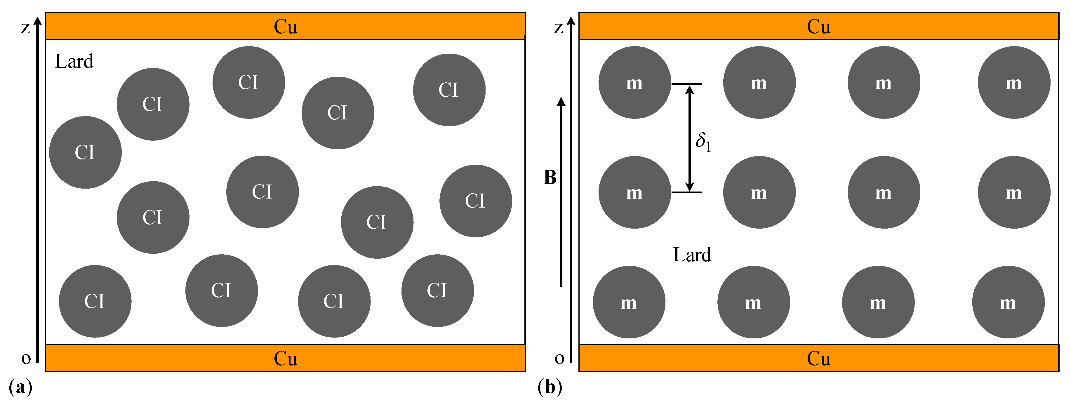
Figure A5.
Cross-section through capacitors with a dielectric composed of lard, GP and CI microparticles (model) under: (a) absence of a magnetic field; (b) presence of a magnetic field. The symbols are the same as above.
Figure A5.
Cross-section through capacitors with a dielectric composed of lard, GP and CI microparticles (model) under: (a) absence of a magnetic field; (b) presence of a magnetic field. The symbols are the same as above.
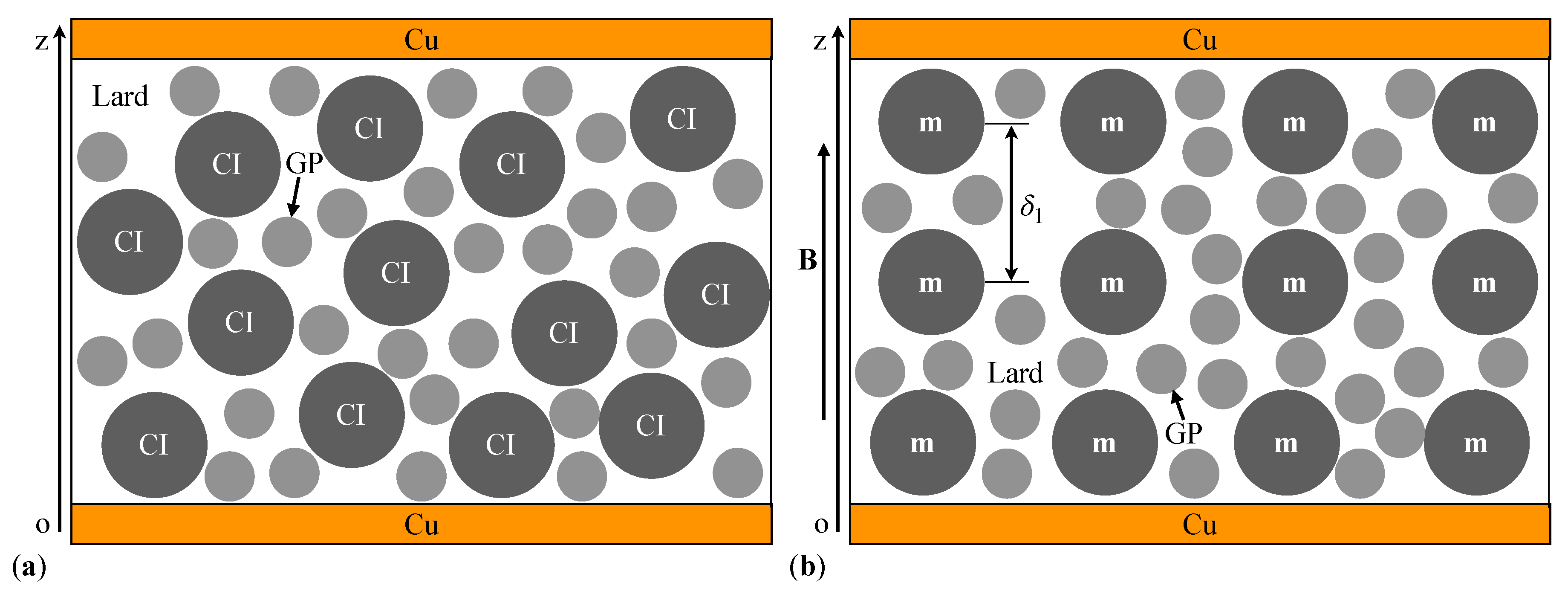
The dipole magnetic moment projected on the Oz coordinate axis is calculated with the expression [41,42]:
where is the magnetic constant of the vacuum. Between the dipoles m (see Figure A4a and Figure A5a), along the Oz axis, magnetic interactions of intensity occur [41,42]:
where m is the magnitude of the dipole moment, and z is the distance between the centers of mass of the dipoles m at a moment . From Equations (A10) and (A11), and for , we obtain:
The negative sign in this expression indicates that the dipoles m in the chain attract each other. In the time interval , the dipoles m in each chain approach by a distance (). The movement of the dipoles m is opposed by the resistance force of the lard. The magnitude of is calculated with the relation [41,42]:
where is the viscosity of the medium in which it takes place the movement of dipoles m.
At an arbitrary moment t, between the quantities and (with ), a dynamic equilibrium occurs, which mathematically can be written as:
and represents the equation of motion for the CI microparticles in the dielectric component between the copper foils of the capacitors . At , the distance between the dipoles m is (with ), and at a moment , the distance between the same dipoles is . With these conditions, we integrate Equation (A14) and obtain:
This equation describes the law of motion of CI microparticles in the capacitors in a magnetic field. Between two dipoles m in each chain, a microcapacitor is formed.
The electric capacitance () of a microcapacitor is approximated by the relation:
where is the dielectric constant of the vacuum, is the relative dielectric permittivity of the suspensions, S is the surface area of the dipoles m, and is the distance between the centers of mass of the dipoles in each chain. For and the expression for () in Equation (A15) inserted in Equation (A16), we obtain the expression for the capacitance of a microcapacitor:
The maximum number of dipoles m in each chain is defined by the expression [13]:
where is the thickness of the suspensions. The capacitors (with ) are in series. Therefore, the equivalent electrical capacitance of a chain of dipoles is:
The number N of dipoles m in the volume of the is estimated with the expression [13]:
where V is the volume of the , and is the volume of a CI microparticle. For and introduced in Equation (A20), the expression for calculating the number N is obtained as follows:
where D is the diameter of the body formed by the .
The number of chains of magnetic dipoles is . Using the expression for N given by Equation (A21) and the value of , we obtain the expression for calculating the number of chains of dipoles m in as follows:
The capacitor chains are electrically connected in parallel through the copper foils. Therefore, the electrical capacitance of the capacitors can be estimated using the relation . By introducing from Equation (A22) and the value of from Equation (A19), we obtain the relation for the capacitance of the capacitors in a magnetic field, as:
The value is the capacitance at the initial moment of the capacitors and has the form:
It is observed from Equation (A23) that the value depends on the geometric dimensions of the CECs, the diameter , the volume fraction of the CI microparticles in the liquid matrix, and the volume fraction of the GP microparticles. By using numerical values , , , H/m , and the values with from Equations (A8), and (A9) we obtain:
and respectively,
References
- Wang, Y.; Xie, W.; Wu, D. Rheological properties of magnetorheological suspensions stabilized with nanocelluloses. Carbohydr. Polym. 2020, 231, 115776. [Google Scholar] [CrossRef]
- Zhao, P.; Du, T.; Ma, N.; Dong, X.; Qi, M. Effect of interfacial shear strength between magnetic particles and carrier liquid on rheological properties of magnetorheological fluids. J. Mol. Liq. 2023, 369, 120929. [Google Scholar] [CrossRef]
- Pei, P.; Peng, Y. Constitutive modeling of magnetorheological fluids: A review. J. Magn. Magn. Mater. 2022, 550, 169076. [Google Scholar] [CrossRef]
- Bica, I.; Anitas, E. Magnetodielectric effects in membranes based on magnetorheological bio-suspensions. Mater. & Des. 2018, 155, 317–324. [Google Scholar] [CrossRef]
- Saberi, H.; Esmaeilnezhad, E.; Choi, H.J. Application of artificial intelligence to magnetite-based magnetorheological fluids. J. Ind. Eng. Chem. 2021, 100, 399–409. [Google Scholar] [CrossRef]
- Jenis, F.; Kubik, M.; Michalek, T.; Strecker, Z.; Zacek, J.; Mazurek, I. Effect of the Magnetorheological Damper Dynamic Behaviour on the Rail Vehicle Comfort: Hardware-in-the-Loop Simulation. Actuators 2023, 12. [Google Scholar] [CrossRef]
- Bica, I. Electroconductive magnetorheological suspensions. Smart Mater. Struct. 2006, 15, N147. [Google Scholar] [CrossRef]
- Wang, S.; Ge, Y.; Chen, W.; Gao, F. A dynamic analytical model on electrical circuit response of magnetorheological clutch. Proc. Inst. Mech. Eng. C 2024, 238, 1968–1977. [Google Scholar] [CrossRef]
- Kumar, S.; Sehgal, R.; Wani, M.; Sharma, M.D. Stabilization and tribological properties of magnetorheological (MR) fluids: A review. J. Magn. Magn. Mater. 2021, 538, 168295. [Google Scholar] [CrossRef]
- Choi, S.B. Sedimentation Stability of Magnetorheological Fluids: The State of the Art and Challenging Issues. Micromachines 2022, 13. [Google Scholar] [CrossRef]
- Narwade, P.; Deshmukh, R.; Nagarkar, M.; Wagh, M. Experimental study and rheology of magneto-rheological fluid for a suspension system. Materials Today: Proceedings, 2023. [Google Scholar] [CrossRef]
- Bica, I.; Anitas, E. Magnetic field intensity effect on electrical conductivity of magnetorheological biosuspensions based on honey, turmeric and carbonyl iron. J. Ind. Eng. Chem. 2018, 64, 276–283. [Google Scholar] [CrossRef]
- Bica, I.; Anitas, E.M.; Averis, L.M.E.; Kwon, S.H.; Choi, H.J. Magnetostrictive and viscoelastic characteristics of polyurethane-based magnetorheological elastomer. J. Ind. Eng. Chem. 2019, 73, 128–133. [Google Scholar] [CrossRef]
- Shixu, L.; Jing, Z.; Jun, L.; Jie, F.; Miao, Y.; Song, Q. Enhancing Effect of Fe3O4/Nanolignocelluloses in Magnetorheological Fluid. Langmuir 2021, 37, 7176–7184. [Google Scholar] [CrossRef]
- Plachy, T.; Rohrer, P.; Holcapkova, P. Gelatine-Coated Carbonyl Iron Particles and Their Utilization in Magnetorheological Suspensions. Materials 2021, 14. [Google Scholar] [CrossRef]
- Sista, K.S.; Dwarapudi, S.; Kumar, D.; Sinha, G.R.; Moon, A.P. Carbonyl iron powders as absorption material for microwave interference shielding: A review. J. Alloys Compd. 2021, 853, 157251. [Google Scholar] [CrossRef]
- Eshgarf, H.; Ahmadi Nadooshan, A.; Raisi, A. An overview on properties and applications of magnetorheological fluids: Dampers, batteries, valves and brakes. J. Energy Storage 2022, 50, 104648. [Google Scholar] [CrossRef]
- Musialek, K.; Musialek, I.; Osowski, K.; Olszak, A.; Mikulska, A.; Kesy, Z.; Kesy, A.; Choi, S.B. A New Type of Hydraulic Clutch with Magnetorheological Fluid: Theory and Experiment. Micromachines 2024, 15. [Google Scholar] [CrossRef]
- Bica, I.; Anitas, E.; Averis, L.; Bunoiu, M. Magnetodielectric effects in composite materials based on paraffin, carbonyl iron and graphene. J. Ind. Eng. Chem. 2015, 21, 1323–1327. [Google Scholar] [CrossRef]
- Kang, S.S.; Choi, K.; Nam, J.D.; Choi, H.J. Magnetorheological Elastomers: Fabrication, Characteristics, and Applications. Materials 2020, 13. [Google Scholar] [CrossRef]
- Fei, C.; Haopeng, L.; Mengmeng, H.; Zuzhi, T.; Aimin, L. Preparation of magnetorheological fluid with excellent sedimentation stability. Mater. Manuf. Process. 2020, 35, 1077–1083. [Google Scholar] [CrossRef]
- Prajapati, H.; Shahanand, J.; Nimkar, H.; Lakdawala, A. Methods for sedimentation study of magnetorheological fluids. Mater. Today: Proc. 2020, 28, 40–44. [Google Scholar] [CrossRef]
- Marikkar, J.; Yanty, N. Effect of Chemical and Enzymatic Modifications on the Identity Characteristics of Lard: A Review. Int. J. Food Prop. 2014, 17, 321–330. [Google Scholar] [CrossRef]
- Zhang, L.; Zhang, K.; Yang, H.; Yue, K.; Liu, R.; Bi, Y.; Ma, C. Characterization of lard from different adipose tissues: Physicochemical properties, thermodynamics characteristics and crystallization behaviors. J. Food Compos. Anal. 2023, 115, 105021. [Google Scholar] [CrossRef]
- Alipal, J.; Mohd Pu’ad, N.; Lee, T.; Nayan, N.; Sahari, N.; Basri, H.; Idris, M.; Abdullah, H. A review of gelatin: Properties, sources, process, applications, and commercialisation. Mater. Today: Proc. 2021, 42, 240–250. [Google Scholar] [CrossRef]
- Janchiva, A.; Ohb, Y.; Choic, S. High quality biodiesel production from pork lard by high solvent additive. ScienceAsia 2012, 38, 95–101. [Google Scholar] [CrossRef]
- Liu, S.; Ye, T.T.; Liu, X.; Wang, Z.C.; Chen, D.W. Pork phospholipids influence the generation of lipid-derived lard odorants in dry rendering process. LWT 2021, 152, 112284. [Google Scholar] [CrossRef]
- Koontanatechanon, A.; Wongphatcharachai, M.; Nonthabenjawan, N.; Jariyahatthakij, P.; Khorporn, T.; Parnsen, W.; Keattisin, B.; Leksrisompong, P.; Srichana, P.; Prasopdee, S.; et al. Effects of Omega-3-Rich Pork Lard on Serum Lipid Profile and Gut Microbiome in C57BL/6NJ Mice. Int. J. Food Sci. 2022, 2022, 9269968. [Google Scholar] [CrossRef]
- Becker, L.C.; Bergfeld, W.F.; Belsito, D.V.; Hill, R.A.; Klaassen, C.D.; Liebler, D.C.; Marks, J.G.; Shank, R.C.; Slaga, T.J.; Snyder, P.W.; et al. Lard and Lard-Derived Ingredients. Int. J. Toxicol. 2023, 42, 58S–60S. [Google Scholar] [CrossRef]
- Julie Chandra, C.S.; Sasi, S.; Bindu Sharmila, T.K. , Material Applications of Gelatin. In Handbook of Biopolymers; Thomas, S.; AR, A.; Jose Chirayil, C.; Thomas, B., Eds.; 2023; pp. 749–782. [CrossRef]
- Iacobescu, G.E.; Bica, I.; Chirigiu, L.M.E. Physical Mechanisms of Magnetic Field Effects on the Dielectric Function of Hybrid Magnetorheological Suspensions. Materials 2021, 14. [Google Scholar] [CrossRef]
- Kalina, K.A.; Metsch, P.; Brummund, J.; Kästner, M. A macroscopic model for magnetorheological elastomers based on microscopic simulations. Int. J. Solids Struct. 2020, 193-194, 200–212. [Google Scholar] [CrossRef]
- Calderon, O.G.; Melle, S. Dynamics of simple magnetorheological suspensions under rotating magnetic fields with modulated Mason number. J. Phys. D: Appl. Phys. 2002, 35, 2492. [Google Scholar] [CrossRef]
- Osial, M.; Pregowska, A.; Warczak, M.; Giersig, M. Magnetorheological fluids: A concise review of composition, physicochemical properties, and models. J. Intell. Mater. Syst. Struct. 2023, 34, 1864–1884. [Google Scholar] [CrossRef]
- Stejskal, J.; Sapurina, I.; Vilčáková, J.; Plachý, T.; Sedlačík, M.; Bubulinca, C.; Gořalík, M.; Trchová, M.; Kolská, Z.; Prokeš, J. Conducting and Magnetic Composites Polypyrrole Nanotubes/Magnetite Nanoparticles: Application in Magnetorheology. ACS Appl. Nano Mater. 2021, 4, 2247–2256. [Google Scholar] [CrossRef]
- Munteanu, A.; amd Lenka Munteanu, T.P.; Ngwabebhoh, F.A.; Stejskal, J.; Trchová, M.; Kubík, M.; Sedlačík, M. Bidisperse magnetorheological fluids utilizing composite polypyrrole nanotubes/magnetite nanoparticles and carbonyl iron microspheres. Rheol. Acta 2023, 62, 461–472. [Google Scholar] [CrossRef]
- Jurca, M.; Vilcakova, J.; Kazantseva, N.E.; Munteanu, A.; Munteanu, L.; Sedlacik, M.; Stejskal, J.; Trchova, M.; Prokes, J. Conducting and Magnetic Hybrid Polypyrrole/Nickel Composites and Their Application in Magnetorheology. Materials 2024, 17. [Google Scholar] [CrossRef]
- Djatna, S.T.; Tedja, I.T.; Fauzi, A.M. Application of Electrical Properties to Differentiate Lard from Tallow and Palm Oil. J. Anim. Sci. Technol. 2013, 10, 32–39. [Google Scholar] [CrossRef]
- Gadhave, R.V. Improving the performance of gelatine glue using biocompatible polymers. Polym. Bull. 2024, 81, 8177–8193. [Google Scholar] [CrossRef]
- Bica, I.; Anitas, E. Magnetic flux density effect on electrical properties and visco-elastic state of magnetoactive tissues. Compos. Part B 2019, 159, 13–19. [Google Scholar] [CrossRef]
- Ji, D.; Luo, Y.; Ren, H.; Wei, D.; Shao, J. Numerical Simulation and Experimental Analysis of Microstructure of Magnetorheological Fluid. J. Nanomater. 2019, 2019, 6312606. [Google Scholar] [CrossRef]
- Bica, I.; Iacobescu, G.E.; Chirigiu, L.M.E. Magneto-Tactile Sensor Based on a Commercial Polyurethane Sponge. Nanomaterials 2022, 12. [Google Scholar] [CrossRef]
Figure 1.
Photographs taken with the OPTIKA microscope (made in Italy): (a) Field of GMs (dark spots) dispersed in a lard film; (b) MRS suspension in a magnetic field with a magnetic flux density of approximately 50 mT. 1 - columns of CI microparticles; 2 - GMs dispersed in lard.
Figure 1.
Photographs taken with the OPTIKA microscope (made in Italy): (a) Field of GMs (dark spots) dispersed in a lard film; (b) MRS suspension in a magnetic field with a magnetic flux density of approximately 50 mT. 1 - columns of CI microparticles; 2 - GMs dispersed in lard.
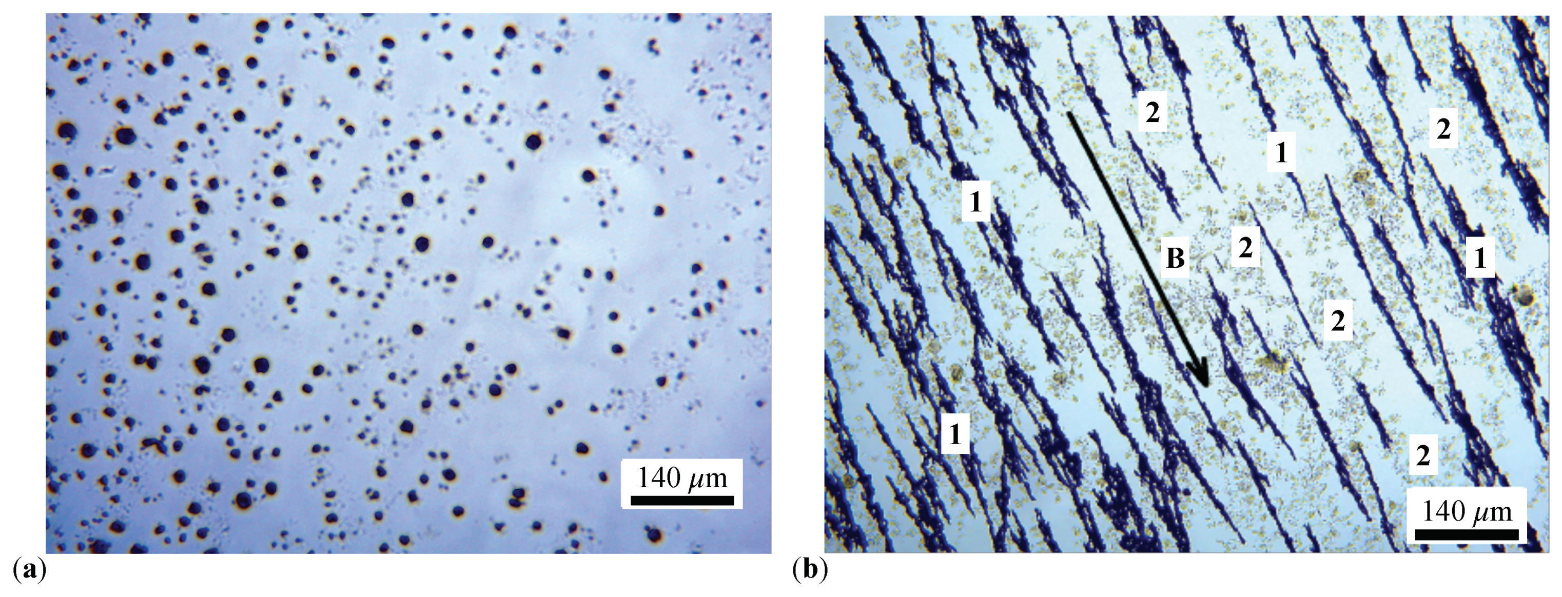
Figure 2.
(a) MC with attached LB. (b) Measurement cell with MRS and attached LB. 1 - copper foil of the LB; 2 - ring made from the RP pad; 3 -flexible electric conductor; 4 - MRS.
Figure 2.
(a) MC with attached LB. (b) Measurement cell with MRS and attached LB. 1 - copper foil of the LB; 2 - ring made from the RP pad; 3 -flexible electric conductor; 4 - MRS.
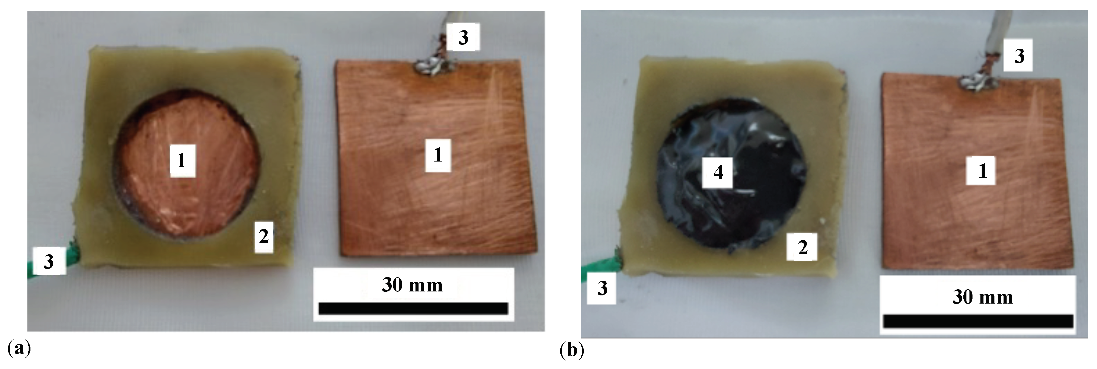
Figure 3.
Images of CEC. (a) Front view. (b) Side view. 1 - CEC body consolidated with ST tape, 2 - flexible electric conductors.
Figure 3.
Images of CEC. (a) Front view. (b) Side view. 1 - CEC body consolidated with ST tape, 2 - flexible electric conductors.
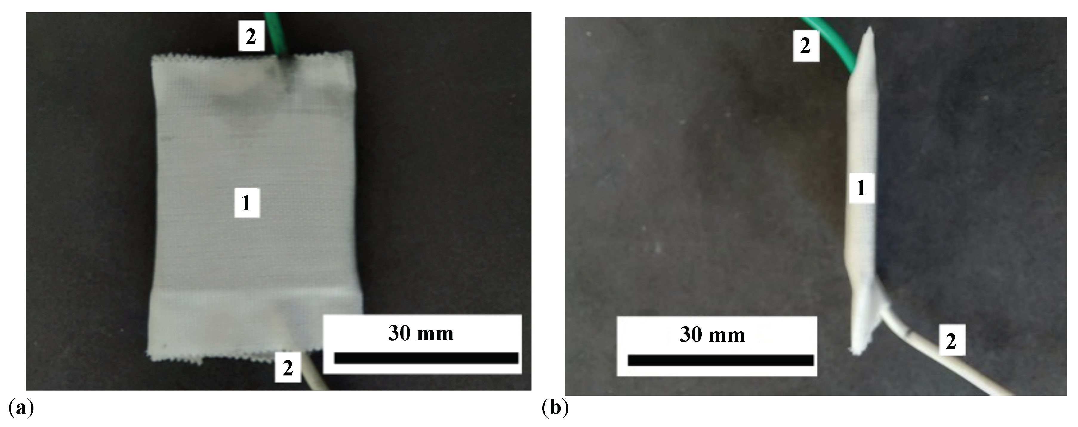
Figure 4.
Experimental setup. DCS - direct current source; Br - RLC bridge; Gs - gaussmeter; h - Hall probe; CEC - electric capacitor; N and S - magnetic poles; B - magnetic flux density vector; I - electric current intensity through the electromagnet coil; 1 - coil; 2 - magnetic yoke; 3 - non-magnetic axis; F - compressive force vector.
Figure 4.
Experimental setup. DCS - direct current source; Br - RLC bridge; Gs - gaussmeter; h - Hall probe; CEC - electric capacitor; N and S - magnetic poles; B - magnetic flux density vector; I - electric current intensity through the electromagnet coil; 1 - coil; 2 - magnetic yoke; 3 - non-magnetic axis; F - compressive force vector.
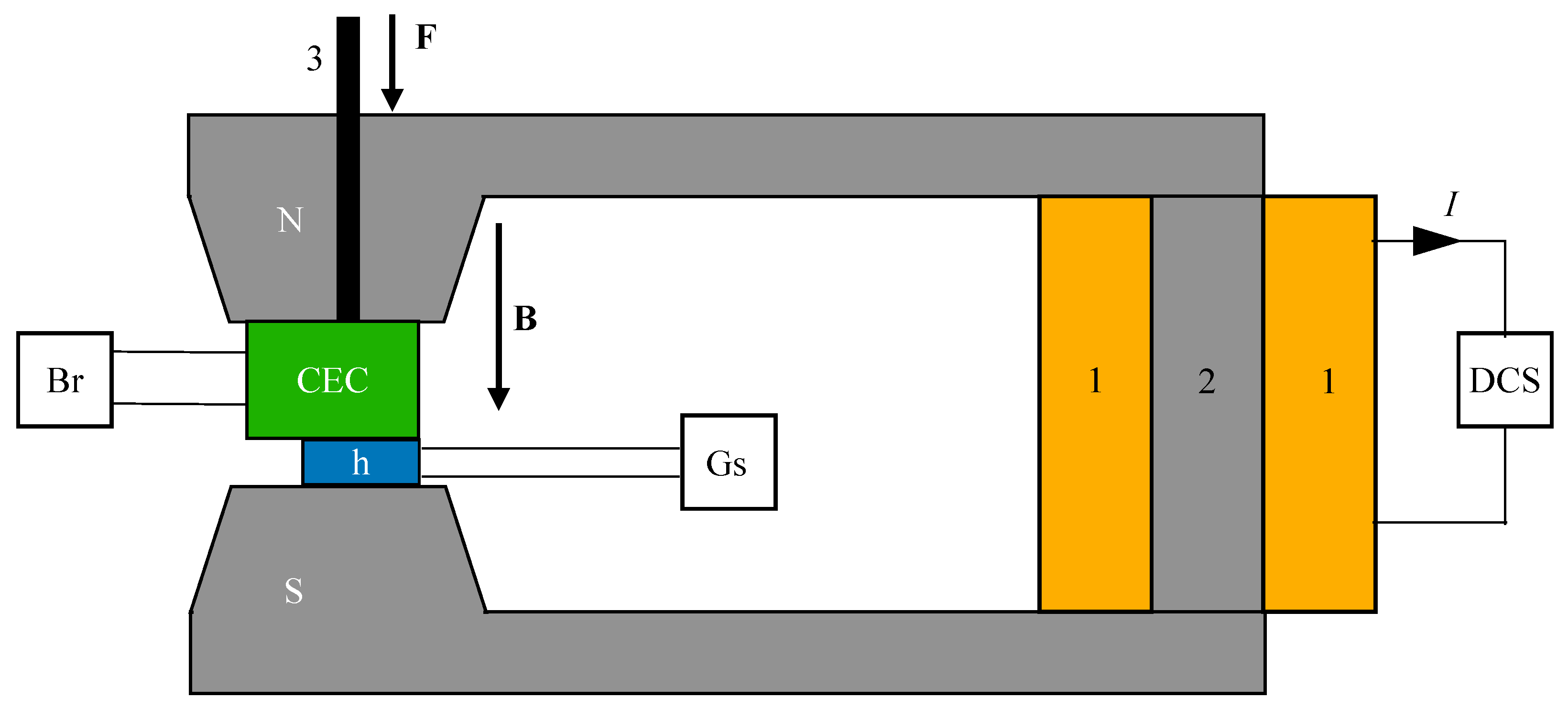
Figure 5.
Variation of the equivalent electrical capacitance (a) and resistance (b) with time t for the electrical capacitors with lard, GP, and respectively CI microparticles. Points - experimental data; continuous lines - linear fits).
Figure 5.
Variation of the equivalent electrical capacitance (a) and resistance (b) with time t for the electrical capacitors with lard, GP, and respectively CI microparticles. Points - experimental data; continuous lines - linear fits).
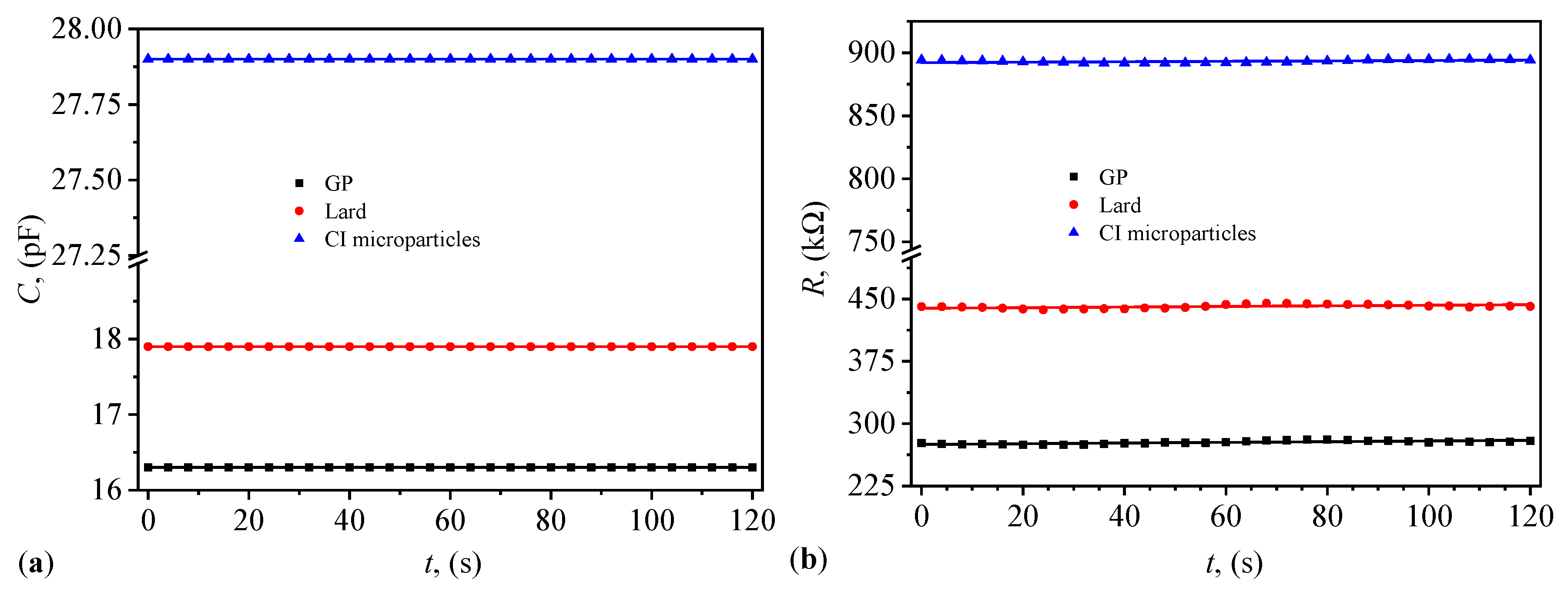
Figure 6.
(a) The electrical capacitance C of capacitors ( and 3) as a function of B values of the magnetic flux density (points - experimental data; lines - polynomial fits; see Table A2 in Appendix E for details). (b) The corresponding average electrical capacitance of the same capacitors.
Figure 6.
(a) The electrical capacitance C of capacitors ( and 3) as a function of B values of the magnetic flux density (points - experimental data; lines - polynomial fits; see Table A2 in Appendix E for details). (b) The corresponding average electrical capacitance of the same capacitors.
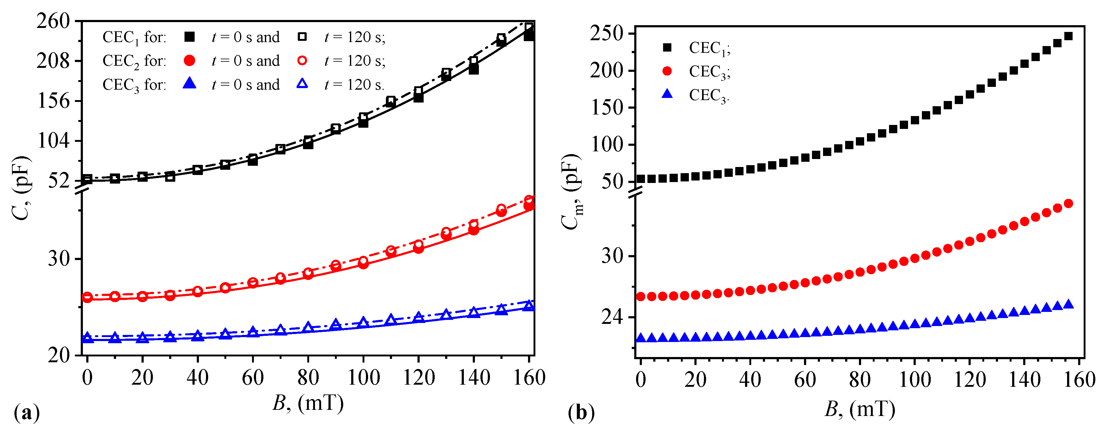
Figure 7.
The viscosity (a) and relative dielectric permittivity (b) of the suspensions (with ) as a function of the magnetic flux density B.
Figure 7.
The viscosity (a) and relative dielectric permittivity (b) of the suspensions (with ) as a function of the magnetic flux density B.
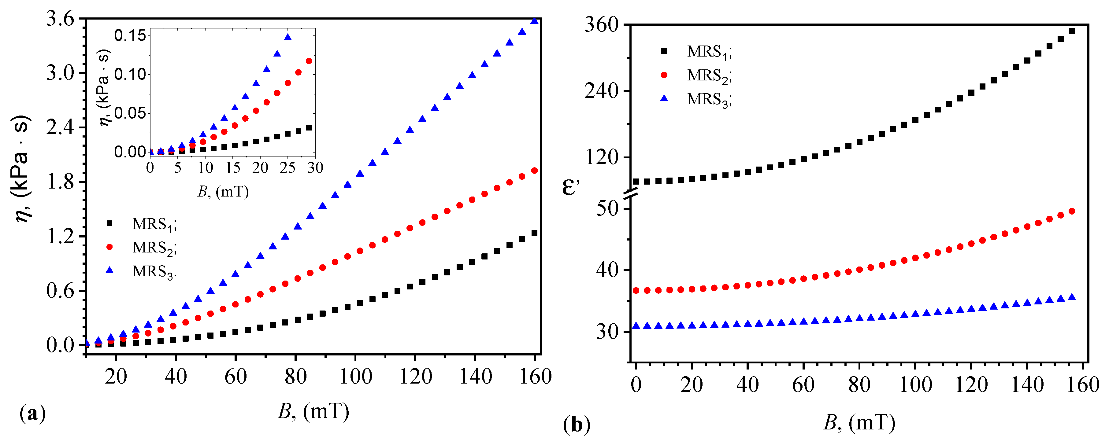
Figure 8.
Magnetodielectric effect MDE in MRS (a), and in MRS and MRS (b) as a function of the magnetic flux density B.
Figure 8.
Magnetodielectric effect MDE in MRS (a), and in MRS and MRS (b) as a function of the magnetic flux density B.
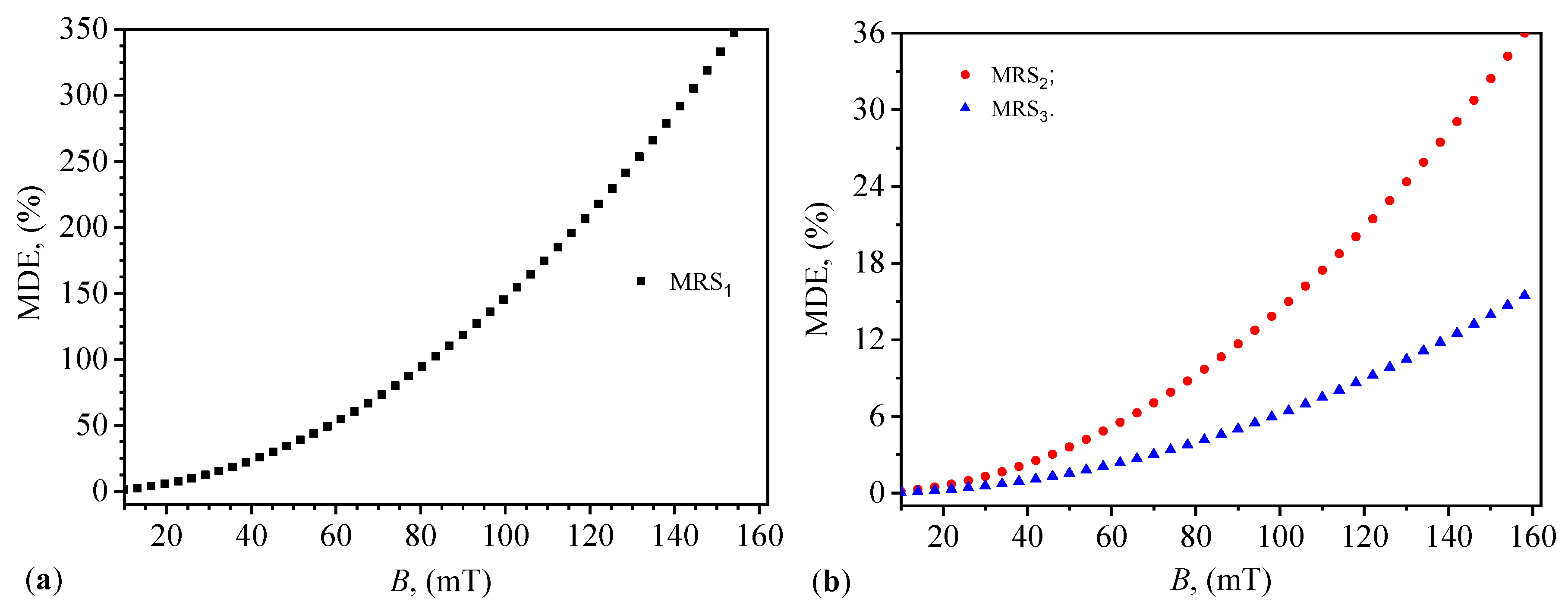
Table 1.
Bulk densities (), relative dielectric permittivity () and dielectric loss factor () for lard, GP and CI microparticles.
Table 1.
Bulk densities (), relative dielectric permittivity () and dielectric loss factor () for lard, GP and CI microparticles.
| (g/cm) | (× 10) | ||
|---|---|---|---|
| Lard | 0.8845 | 25.1483 | 8.09291 |
| GP | 0.5649 | 22.9860 | 5.091925 |
| CI | 3.3600 | 39.339 | 2.515722 |
Table 2.
Volumes V and volume fractions of the MRSs components.
| (cm) | (cm) | (cm) | (vol.%) | (vol.%) | (vol.%) | |
|---|---|---|---|---|---|---|
| MRS | 3.6 | 0.4 | 0.0 | 90 | 10 | 0 |
| MRS | 3.2 | 0.4 | 0.4 | 80 | 10 | 10 |
| MRS | 2.8 | 0.4 | 0.8 | 70 | 10 | 20 |
Disclaimer/Publisher’s Note: The statements, opinions and data contained in all publications are solely those of the individual author(s) and contributor(s) and not of MDPI and/or the editor(s). MDPI and/or the editor(s) disclaim responsibility for any injury to people or property resulting from any ideas, methods, instructions or products referred to in the content. |
© 2024 by the authors. Licensee MDPI, Basel, Switzerland. This article is an open access article distributed under the terms and conditions of the Creative Commons Attribution (CC BY) license (https://creativecommons.org/licenses/by/4.0/).
Copyright: This open access article is published under a Creative Commons CC BY 4.0 license, which permit the free download, distribution, and reuse, provided that the author and preprint are cited in any reuse.