Submitted:
06 June 2024
Posted:
11 June 2024
You are already at the latest version
Abstract
Part II, like Part I, discusses geometry, kinematics and statics in detail without taking into account power losses in meshing. The main goal of Part II, however, is to prove that there are complex and structurally coupled planetary gear systems, i.e. containing a closed circuit in which no circulation of power flow is generated. The power flow analysis is also carried out using the direct method, with a slight modification in the way of writing the equations identifying active and passive gears, i.e. at the same time the directions of power flow on all transmission paths. The analysed planetary gear system (PGS) is characterised by mobility equal to 1, i.e. single degree of freedom (DoF). It consists of three subsystems in the form of the 2KH type planetary units connected in series-parallel, specially selected to demonstrate the thesis of this paper. It consists of three subsystems in the form of single planetary subsystems of the 2KH type connected series-parallel, specially chosen to illustrate the thesis of this paper.
Keywords:
pseudo-coupled planetary gear systems
; series-parallel planetary gear systems
; power flow
; circulating power flow
1. Introduction
Due to their structure and parallel connection of subsystems, PGSs are characterised not only by multi-path power transmission but also by the phenomenon of power closure, commonly called power circulating inside, at least one parallel connected elementary subsystem in the form of a closed circuit. As demonstrated in papers [1,2,3], this phenomenon can be a source of even a large overload of gears, shafts and bearings of a closed subsystem. In the case of an unfavorable distribution of power on individual paths, an additional reduction in efficiency may be revealed. Therefore, after determining the directions of power flow, power losses caused by friction in the meshing and efficiency should be determined. In the case of an unfavorable distribution of power on individual paths, an additional reduction in efficiency may be revealed.
However, the atlas of planetary gears [4] contains kinematic diagrams of several three-row cylindrical series-parallel PGSs in which there is no phenomenon of power closure inside closed parallel connected elementary subsystem. At the same time, in the extensive literature review included in Part I regarding methods of calculating power flow in complex and coupled PGSs, not a single paper or book was found that discussed the possibilities of avoiding the very harmful phenomenon of circulating power flow. Simply put, in all planetary transmissions there were closed subsystems in which the phenomenon of power flow circulation occurred. Therefore, in Part II it will be checked whether such three-row cylindrical series-parallel PGSs actually exist. If they exist, it should also be possible to find at least one design feature that determines the lack of circulation of power flows in closed subsystems.
A priori such PGSs could be called semi-coupled or pseudo-coupled because coupled PGSs must be structurally and dynamically coupled. Structural coupling, manifested by the presence of closed subsystems, results from their parallel connection. However, there is no circulation of power streams in these subsystems, i.e., no dynamic coupling.
The cylindrical PGS analysed in Part II (Figure 1(a)(b)) is very similar in structure to the PGS analysed in [3] (Figure 4(a)). It consists of two subsystems A and B in the form of solar-type units as elementary 2KH planetary gears and one star-type gear C – (Figure 2(a)(b)). Subsystems are connected in series-parallel. Also, the number of DoF of both PGSs is the same:
because the number of active members , the number of lower pairs and the number of higher pairs .
First subsystem A type 3(a) - (Figure 2(a)(b) and Figure 3(a)) has mobility equal to one and is connected in series with the next two DoF subsystem B type 4(a) (Figure 4(a)) via the shaft of carrier and the shaft of sun gear 4 (Figure 1(a) and Figure 2(a)(b)). Subsystem B is connected in parallel with the star gear subsystem C type 3(b) (Figure 3(b)) through the shafts of carrier with the shaft of ring gear 9 and additionally through the shaft of ring gear 6 with the shaft of sun gear 7 (Figure 2(a),(b)). Sun gear 7 and ring gear 9 are movable elements of the C subsystem, while the carrier is fixed. Therefore, the single DoF subsystem C is not a typical 2KH planetary unit, but a star-type gear (Figure 3(d)). The unit type names 3(a), 4(a) and 3(d) are assigned to subsystems A, B and C respectively as shown in Figure 3(a), Figure 4(a) and Figure (3b).
2. Materials and Methods
2.1. Algorithm for determining the Power Stream Flow in PGS without Power Loss
Determining the flow directions of power streams in closed PGSs can be very simple. It is enough to introduce an explicit distinction between the active and passive shafts of each subsystem. Namely, when the torque vector is consistent with the angular velocity vector, then the shaft power as a product of angular velocity and torque is active, because it is transferred to the analysed subsystem. Otherwise, the power is passive because it is transferred outside the subsystem. At the same time, the torque is then active or reactive, respectively. Determining the flow directions of power streams in closed PGSs can be very simple. It is enough to introduce an explicit distinction between the active (driving) and the passive (driven) shafts of each subsystem. Namely, when the torque vector is consistent with the angular velocity vector, then the shaft power as a product of angular velocity and torque is active because it is transferred to the analysed subsystem. Otherwise, power is passive, i.e., transferred outside the subsystem. At the same time, the torque is then active or reactive, respectively. Therefore, determining the directions of flow of power streams in closed PGSs only requires prior detailed analyses of kinematics (determination of angular velocities) and statics (determination of torques without taking into account power losses).
Based on the above considerations, a detailed algorithm for determining the direction of the stream power flow can be proposed. Of course, this is a universal algorithm because it was also used in Part I to analyse the flow of power streams in fully coupled PGS:
- a)
- b)
- determination of the magnitudes and directions of angular velocities of gears and carriers in subsequent subsystems - subsubsection 3.3.1 and and ,
- c)
- determination of the magnitudes and directions of action of the torques loading the shafts of each of the subsystems (at this stage of calculations, without taking into account power losses) – subsection 2.2, subsubsection 3.3.2 and Appendix C,
- d)
- determining the active and passive shafts of each of the transmission subsystems and the directions of the flow of power streams – subsection 2.2, subsubsections 3.3.4 and 3.3.5.
2.2. Static Analysis without Taking Into Account Meshing Friction and Identification of Active and Passive Shafts
It is known that the dot product of the same-directed vectors of torque and angular velocity , where , i.e., power is active. This means that power is supplied to the subsystem through the active shaft. In the case of these vectors oppositely directed, their product , i.e., the power is reactive and this means that the power is discharged from the subsystem through the passive shaft. Then, the torque vector is a reaction torque, marked as - the resistance moment of the shaft of the adjacent driven subsystem. Thus, when identifying the active and passive shafts of subsystems connected in series or in parallel, two basic conditions for transferring power from or to a subsystem are used:
for the driving shaft, the vectors of the angular velocity and the torque are in the same direction (),
for the driven shaft, the vectors of the angular velocity and the reaction torque are oppositely directed ().
Unfortunately, these are only the conditions necessary to be met. Sufficient conditions are a system of governing equations derived separately for each of the subsystems with mobility equal to 1 or 2. Each such system consists of a torque equilibrium equation and practically one energy balance equation in the reference system related to the stationary body, because the second equation of the energy balance in the system associated with the carrier can only be used for verification. A certain difficulty in deriving these equations for the subsystem with mobility equal to 2 is the lack of identified characters of the two shafts (Figure 4). The nature of the third shaft is known because it is either the input or output shaft of the PGS or it is an extension of the shaft of the adjacent subsystem whose shafts have been identified earlier (subsubsection 3.3.4). If for instance, the shaft of an adjacent subsystem is passive, then the shaft of the analysed subsystem is active.
In the general case, there are three versions of the governing equations, assuming that the shaft of the sun gear is active.
First version modelling the type 4(a) subsystem:
where conditions for active and passive shafts are as follows: , and .
Second version modelling the type 4(e) subsystem:
where conditions for active and passive shafts are as follows: , and .
Third version modelling the type 4(f) subsystem:
where conditions for active and passive shafts are as follows: , and .
The fourth version with three active shafts is impossible to implement, both from a mathematical and technical point of view. Reasons: the positive terms of the sum cannot be zero and each gear transmission must have at least one input and one output.
Using the "trial and error" method, it is possible to choose the right version of governing equations, because the magnitude and direction of active and reactive torques , as well as the products of torques and angular velocities () and () are known.
Of course, in the case of subsystems with mobility equal to 1, there is no problem with identifying the power flow path, because such a subsystem depending on the type (Figure 3) has known input and output shafts. Moreover, its third shaft is fixed and hence its angular velocity and power are respectively and , where , or . Then the subsystem equilibrium equations are determined directly without fitting the conditions for active and passive shafts with one of the three versions of the equations ((2),(3)), ((4), (5)) or ((6), (7)).
3. Case Study
3.1. Case Study Subjects
The purpose of this chapter is to present in detail the graphical and analytical method of determining the directions of power stream flow in the pseudo-coupled PGS with very similar geometrical structures and the same gear ratios , input angular velocities and input torques . The forms of these two PGSs have been selected in terms of their geometrical structure so that their kinematic and dynamic similarities and differences can be demonstrated.
Figure 5(a)(b)(c) shows the diagram of the PGS in the form of kinematic blocks A, B and C. The subsystem blocks A, B and C are additionally separated in the kinematic diagrams in Figure 2(b). The names of subsystem types, according to Figure 3 and Figure 4, are shown in Table 1. All blocks shown in Figure 3 correspond to two-shaft subsystems, i.e., they contain 2 moving shafts and thus have a single DoF each. On the other hand, all blocks shown in Figure 4 correspond to three-shaft subsystems, i.e., they contain 3 movable shafts and thus have two DoF each.
3.2. Data
Table 2 presents data on the geometry of the gears of the analysed PGS. Parameter symbols: , , - number of teeth and pitch diameters and gear modules ( to ), , - carriers radii and number of planet gears (), respectively. There is also input torque and input angular velocity (rotation velocity) ().
3.3. Power Flow Paths in PGS
3.3.1. Calculations of Angular and Tangential Velocities
Identification of the power flow paths in the pseudo-coupled PGS is carried out according to a similar algorithm used for the coupled PGS [3]. The values of the fixed carrier transmission ratios of subsystems A, B and C and pairs of sun and planet gears are listed in Table 3 based on calculations in Appendix A. These parameters are necessary to determine the magnitude and direction of the angular velocity of the gears and carriers of the PGS.
Detailed calculations of the angular velocities of sun, rim, planet gears and carriers are provided in Appendices A and B, while the tangential velocities are in Appendix B. In addition, the angular velocity vectors are presented in Table 4 and their directions are shown in Figure A1 to Figure A3, where is the unit vector of angular velocity. Also, the directions of tangential velocity vectors are shown in Figure A1 to Figure A3 and their magnitudes in Table A1 and Table A2.
From the equations (A1), (A2) and (A3) the formula for the total gear ratio of the PGSs was derived:
where the fixed carrier transmission ratio is:
3.3.2. Transmission Ratios on Power Flow Paths in Subsystems of PGS
3.3.3. Calculations of the Shaft Torques of Subsystems A, B, C
- Shaft torques on the shafts of one DoF subsystem A
According to Figure 5 and Table 2, the vector torque on the input shaft I of the PGS is given , i.e., its magnitude is equal and is a unit vector of torques. Therefore, it was used to calculate the active and reactive torque vectors , and , on the shafts of carrier and ring gear 3, respectively in Appendix C1. Equilibrium equations (A26) to (A38) were derived using the free body diagram based on Figure A4 and Figure A5. The vectors of the calculated torques are presented in Table 6. In subsubsection 3.3.4 they will be used together with the vectors of angular velocities and to select the appropriate system of equations to determine one power flow path in the subsystem A.
- Shaft torques of the two DoF subsystem B
According to equation (A40) and Figure A4 and Figure A5 the torque acting on the input shaft of sun gear 4 is equal to . Therefore, it was used to calculate the active and reactive torques , and , of the carrier and ring gear shafts, respectively. The magnitudes and vector directions of these torques were determined in Appendix C2 from the equilibrium equations (A39) to (A52) based on Figure A6. The magnitudes of the calculated torques are presented in Table 7. In subsubsection 3.3.4 they will be used together with the angular velocities and (from Table 4) to select the appropriate system of equations to determine the two power flow paths in subsystem B.
- Shaft torques of the one DoF subsystem C
According to equations A54, A55 and Figure A7, the torque acting on the shaft of the ring gear 7 are given . Therefore, it was used to calculate the active and reactive torques , and , of the shafts of carrier and ring gear 9, respectively. Magnitudes and directions of these torques were determined in Appendix C3 from the equilibrium equations (A56) to (A64) based on Figure A8. The vectors of the calculated torques are presented in Table 8. In subsubsection 3.3.4 they will be used together with the vectors of angular velocities and (from Table 4) to select the appropriate equation to determine the one power flow path in subsystem C.
3.3.4. Power Flow Paths in the Subsystems A, B and C of the PGS
- Identification of the power flow paths in the type 1(a) subsystem A
Subsystem A has a single DoF and is type 3(a) according to Figure 2(b), Figure 3(a), Figure 5(c) and Table 1. Therefore, it has one power flow path from the input shaft of sun gear 1 to the output shaft of carrier , because the shaft of ring gear 3 is fixed. In this case, the governing equation can be determined directly, just like equations (2) and (3):
where adapted new indices , , (according to Figure 3(a)) and (according to Table 2).
The form of these equations is consistent with the assumption that in this subsystem having a single DoF the shaft of sun gear 1 is active (input), the shaft of carrier is passive, and the ring gear 3 is fixed () (Figure 6). These assumptions correspond to the conditions: , and . The directions of the torque vectors , and angular velocity vector are shown in Figure 6(a) and in the Table 6. The torque must also satisfy the additional energy balance equation in the reference frame related to the carrier , so there is a second way to check its magnitude in addition to the free body diagram (Figure A5 and equation (A38)) used in Appendix C1:
The type of subsystem B cannot be determined directly, as it was done for a single DOF subsystem A. Subsystem B has two DoF and, according to Figure 6(b), it is only known that the shaft of sun gear 4 is an active (input). Figure 4(a), Figure 4(e) and Figure 4(f) present three possible cases of power flow paths that may occur here. Thus, the correct type case selected from types 4(a), 4(e), and 4(f) must satisfy one of the three versions of equation pairs ((2)-(3)), ((4)- (5) ) or ((6)- (7)) for this subsystem as given below.
Conditions of the first possible case of two paths of the power flow path from sun gear 4 to ring gear 6 and carrier (it is assumed that shafts of the ring gear 6 and carrier are passive, as for type 4(a) – Figure 4(a)):
Conditions of the second possible case of two paths of the power flow from sun gear 4 and carrier to ring gear 6 (it is assumed that the shaft of the ring gear 6 is passive and the shaft of the carrier is active, as for type 4(e) – Figure 4(e)):
Conditions of the third possible case of two paths of power flow from sun gear 4 and ring gear 6 to carrier (it is assumed that the shaft of the ring gear 6 is active and the shaft of the carrier is passive, as for type 4(f) – Figure 4(f)):
The system of equations ((2)-(3)) is satisfied by a pair of conditions (13), and therefore the adapted version of these equations takes the following form for subsystem B indices:
where adapted new indices , and (according to Figure 4(a)).
The equations (16) and (17) are a mathematical model of subsystem B type 4(a), in which the input shaft of sun gear 4 must be driving , while the shafts of the ring gear 6 and the carrier are driven ( and ). The directions of torque vectors , and are shown in Figure 7(a). The torque must also satisfy the additional equation of the energy balance in the mobile reference frame related to the carrier , so there is a second way to check its magnitude in addition to the free body diagram (Figure A6) and equations (A52) used in Appendix C2:
- Identification of the power flow paths in type 3(b) subsystem C
Subsystem C has a single DoF and is type 3(b) according to Figure 7(b), Figure 8 and Table 1. Therefore, it has one power flow path from the input shaft of sun gear 7 to the output shaft of ring gear 9 because the shaft of carrier is fixed. In this case, the governing equation can be determined directly, just like equations (2) and (3):
where adapted new indices , , (according to Figure 3(b)) and (according to equations (A54) and (A55)).
The form of these equations is consistent with the assumption that in this subsystem having a single DoF the shaft of sun gear 7 is driving, the shaft of ring gear 9 is driven, and the shaft of carrier is fixed (). These assumptions correspond to the conditions:
The directions of the torque vectors
and are shown in Figure 8. The torque must also satisfy the additional energy balance equation in the reference frame related to the carrier , so there is a second way to check its magnitude in addition to the free body diagram used in Appendix C3 - equation (A63):
For the previously determined torques acting on the shafts of carriers and
, it is possible to calculate the total torque on the output shaft II of PGS:
and check the total gear ratio (for efficiency ):
Identification of the power flow path in PGS (summary)
3.3.5. Powers and Power Ratios on the Shafts of Subsystems A, B and C of PGS
- Calculations of powers and power ratios on the shafts of subsystem A
Table 10 and Table 11 show that in accordance with the assumption 100 % of the power supplied to subsystem A is transferred to the input shaft of subsystem B.
Calculations of powers and power ratios of the subsystem B
Table 12 shows that the shafts of the ring gear 6 and the carrier are reactive because the powers and . Therefore, unlike the same subsystem B in coupled PGS [3], there is no phenomenon of circulation of the power stream. Table 13 shows that there is also no overloading of any of the elements of this and the next subsystem.
Calculations of powers and power ratios on the shafts of subsystem C
where .
The shaft of the carrier is fixed, so the power (Table 14). Table 15 shows, among others, the value of the power ratio equal to , which means that, according to the assumption, in the analysed PGS no power loss occurred (as it was assumed that losses due to friction in the gears were not taken into account).
4. Results
The aim of this paper was to check whether there are actually closed, i.e., series parallel three-row PGS, in which there is no power flow circulation phenomenon. According to the algorithm presented in subsection 2.1, Table 9 and subsubsubsection 3.3.5 the searched paths and directions of power flow of the power flow streams were determined.
The search results are shown in Figure 9(a), where it can be seen that in none of the subsections, and especially in the closed circuit composed of two-DoF B and a single-DoF C subsystems, there is no power flow circulation. According to the above, subsection B, which forms a closed circuit with subsection C (composed of gears 5, 6, 7, 8, 9 and carrier ) is only structurally coupled, i.e., semi-coupled. It is not dynamically coupled due to the lack of power flow circulation. There is also no increase in the power ratio above 100%, which was a normal phenomenon in coupled PGS (Figure 9(b) [3]).
It is proposed that PGS containing at least one closed circuit without visible dynamic coupling be called pseudo-coupled or semi-coupled. For comparison, Figure 9(b) [3] next to Figure 9(a) shows that in a very similar circuit consisting of gears 5, 6, 7, 8 and two carriers and , there is dynamic coupling and the resulting significant increase in the power ratio of over 100%. This means that the gears, bearings and shafts contained in the closed circuit are significantly overloaded. The worst thing is that this excess load cannot be determined by typical static calculations of nominal torques as presented in Appendix C. This very harmful dynamic coupling effect is not visible in Figure 9(a) showing the power flow together with the power ratios in pseudo-coupled PGS.
Recognising the differences between dynamically uncoupled PGS (Figure 9(a)) and dynamically coupled PGS (Figure 9(b)) is easy, because in the first system, the shaft of carrier is passive (transferring power to the output shaft II PGS), while in the second system, the shaft of carrier is active (transferring power to the internally closed system consisting of gears 5, 6, 7, 8 and carriers and ). However, the shaft of carrier in the second closed circuit composed of gears 1, 2, 3, 4, 5 and carriers and is passive (Figure 9(b)), as a result of which this subsystem is not dynamically coupled.
Since no power losses were considered in both PGSs, the power on their output shafts II, even despite the power circulation in the second, reached 100% of the input power.
5. Conclusions
In this paper, which is the second part of a three-part study, a systematic methodology of determining the paths and directions of power flow in compound cylindrical three-row series-parallel PGS has been presented. This single-DoF pseudo-coupled PGS consisted of three 2KH type subsystems (two a single-DoF and one two-DoF) contains a single-closed circuit. The aim of developing the second part of the study was:
- 1)
- analytical verification of whether a pseudo-coupled (in which there is no power flow circulation phenomenon) three-row PGS design is indeed possible,
- 2)
- comparison of the power flow paths and directions in two structurally similar PGSs, the first of which turned out to be only pseudo-coupled with the second coupled PGS analysed in part I,
- 3)
- initial adaptation of the algorithm to automate analysis of coupled and pseudo-coupled three-row series-parallel PGSs,
- 4)
- development of the rules for designing pseudo-coupled complex PGSs (without circulation of the power streams in closed circuits).
The algorithm used in Part II is significantly different from the algorithm used in Part I and is as follows (assuming that the geometric parameters of PGS are already given):
- 1)
- checking the PGS mobility, dividing the PGS structure into blocks (subsystems) and closed circuits, determining the fixed carrier transmission ratio of individual subsystems,
- 2)
- modified method determination of the angular velocity magnitudes of gears and carriers as well as gear ratios of individual subsystems and PGS using the Willis relationship,
- 3)
- modified method determination of the active and reactive torque magnitudes, as well as tangential and radial forces, using the free body diagram, necessary to calculate the active or passive powers transmitted by the shafts of individual subsystems,
- 4)
- original method determination of the paths with power flow directions by defining the role of individual subsystem shafts (active shafts - supplying power to the subsystem, passive shafts discharging power from the subsystem),
- 5)
- calculation of the power values and the power ratios as a check of the algorithm.
Conclusions resulting from the modified algorithm in terms of achieving the planned effects:
- 1)
- the main goal set in Part II was achieved because after analytical verification it was found that it was possible to design a cylindrical pseudo-coupled three-row series-parallel PGS (without circulation of the power streams in closed circuits),
- 2)
- notation of kinematic equations in vector form, after transformation in matrix form, significantly simplifies the determination and interpretation of the angular velocity vectors (magnitudes and direction), so it is unnecessary to use the method using the Willis formula and/or graphic-analytical or other methods,
- 3)
- distinction concept between active - reactive torques and active - passive shaft powers, notation the torque and power balance equations in vector form (such as governing equations (2)-(3), (4)-(5) and (6)-(7)) greatly simplify the selection of types two-DoF subsystems (there is no need to use the "free body diagram" method unless only to check the results obtained from the system of equations in matrix notation),
- 4)
- the direct method described above, unlike modelling in terms of graphs, e.g., contour graphs, is not suitable for automatic generation and solution of kinematics, statics and balance power equations,
- 5)
- development of the rules for designing pseudo-coupled complex PGSs is not possible based on the analysis of only one pseudo-coupled PGS; it seems that each characteristic feature of pseudo-coupled PGS cannot be consistent with the characteristic feature of coupled PGS treated as a counter-example.
Due to the limited recognition of the advantages and disadvantages of pseudo-coupled and coupled PGSs, based only on one comparison, the following research in this area is planned:
1) comparison of the meshing power losses in pseudo-coupled and coupled PGSs gearing - Part III (75% progress),
2) searching for pseudo-coupled PGSs of the cylindrical-bevel or CVT-bevel type,
3) search for pseudo-coupled cylindrical PGSs with a mobility of two or three (three-shaft or four-shaft),
4) automation of PGSs design, among others using contour graphs.
Author Contributions
“Conceptualization, J.D.; methodology, J.D. and T.K.; software, J.D. and K.S.; validation, J.D. and T.K.; formal analysis, J.R.; investigation, T.K. and K.S; writing—original draft preparation, J.D. and T.K.; writing—review and editing, J.D. and T.K.; visualization, J.D.; J.R. and K.S.; funding acquisition, J.D. and T.K. All authors have read and agreed to the published version of the manuscript.” Please turn to the CRediT taxonomy for the term explanation. Authorship must be limited to those who have contributed substantially to the work reported.
Conflicts of Interest
“The authors declare no conflict of interest.”
Appendix A
Appendix A.1. Willis Formulas for Subsystems A, B, C and PGS
Appendix A.2. Willis Formulas for Sun Gear and Planet Gear Pairs
Appendix A.3. Calculations of Angular Velocities of Gears and Carriers of PGS
Angular velocities and of the carrier and sun gear 4, respectively:
i.e., and (Figure A1b, Figure A2a).
Angular velocities of the carrier , ring gear 9 and output shaft II:
i.e., and (Figure A2 and Figure A3).
Angular velocity of the ring gear 6 and sun gear 7 (Figure A2 and Figure A3):
i.e., and (Figure A2a,b, Figure A3).
PGS gear ratio (with fixed carrier and ring gear 3):
Angular velocity of the planet gear 2:
i.e., and .
Angular velocity of the planet gear 5:
i.e., and .
Angular velocity of the idler gear 8:
i.e., and .
Appendix B
Appendix B.1. Calculation of Tangential Velocities of the Gears of PGS
Tangential velocities , , of sun gears 1, 4, 7 respectively, at the points of contact with the planet gears 2, 5 and the idler gear 8 are determined from the following formulas (according to Figure A1, Figure A2 and Figure A3):
where: Thus:
where:
Tangential velocities , , of the ring gears 3, 6, 8 respectively, at the points of contact with the planet gears 2, 5 and the idler gear 8 are determined from the following formulas (according to Figure A1, Figure A2 and Figure A3):
where: and , (these are ring gears).
Thus:
,
where:
, - contact point of gear i with gear j,
Assumption that the tangential velocities of the planet gears , , , , , are equal to the respective magnitudes of velocities of the sun and ring gears at their points of contact (according to Figure A1, Figure A2 and Figure A3):
The calculated magnitudes of these velocities are given in Table A1.

Table A1.
Calculated magnitudes of tangential velocities in m/s.
| 0 |
Appendix B2. Determination of Instantaneous Centre of Zero Velocity
and Velocities of the Planet Gear 2 with Carrier
The coordinate of the instantaneous centre of rotation of the planet gear 2
According to Figure A1a, the instantaneous centre of rotation of the planet gear 2 is located at the point of contact with the fixed ring gear 3, because for also tangential velocities .
Figure A1.
Angular and tangential velocities of: (a) The elements of subsystem A; (b) The pair of carrier and sun gear 4.
Figure A1.
Angular and tangential velocities of: (a) The elements of subsystem A; (b) The pair of carrier and sun gear 4.

Tangential velocity of the planet gear 2 at the point of contact with sun gear 1:
where and - contact point of planet gear 2 with sun gear 1.
Tangential velocity of the planet gear 2 at the point of contact with ring gear 3:
where .
Tangential velocities of the centre of planet gear 2 at the point of contact with carrier and of the carrier at the point of contact with the centre of planet gear 2 (Figure A1):
Appendix B3. Determination of Instantaneous Centre of Zero Velocity
and Velocities of the Planet Gear 5 with Carrier
The coordinate of the instantaneous centre of rotation of the planet gear 5 (Figure A2a)
where and .
Tangential velocity of planet gear 5 at the contact point with sun gear 5 (Figure A2):
Tangential velocities and of the centre of planet gear 5 and carrier , respectively (Figure A2a):
where:
Figure A2.
Angular and tangential velocities of: (a) The elements of subsystem B; (b) The pair of gears 6 and 7.
Figure A2.
Angular and tangential velocities of: (a) The elements of subsystem B; (b) The pair of gears 6 and 7.

Appendix B3. Determination of Instantaneous Centre of Zero Velocity
and Velocities of the Planet Gear 8 with Carrier
The coordinate of the centre of rotation of the idler gear 8 (Figure A3)
The carrier is fixed , so gear 8 is not a planetary gear but an idler gear. So its centre of rotation is the geometric centre of the circle (Figure A3).
Figure A3.
Angular and tangential velocities of the subsystem C.

Angular velocity of the idler gear 8 :
where: , - contact point of idler gear 8 with ring gear 9, (Table A1).
Velocity magnitude of the centre of idler gear 8 and of carrier (Figure A3):
Table A2.
Velocity magnitudes of the centres of planet gears 2, 5, idler gear 8 and carriers h2, h5, h8 in m/s.
Table A2.
Velocity magnitudes of the centres of planet gears 2, 5, idler gear 8 and carriers h2, h5, h8 in m/s.
| 0.693 | 0.012 | 0 |
Appendix C
Appendix C1. Calculation of Torques, Tangential and Radial Forces Acting on Gears 1, 2, 3 and Carrier
The tangential force exerted by planet gear 2 on sun gear 1 (Figure A4(a)):
where: , , - contact point of sun gear 1 with planet gear 2.
The radial force exerted by planet gear 2 on sun gear 1 (Figure A4a):
where pressure angle .
Figure A4.
Free body diagrams of the subsystem A elements: (a) Gears 1, 2, 3; (b) Carrier .

The tangential force exerted by sun gear 1 on planet gear 2:
i.e., .
The radial force exerted by the sun gear 1 on planet gear 2:
The tangential force exerted by ring gear 3 on planet gear 2 (Figure A4a):
where: , , .
The tangential force exerted by planet gear 2 on ring gear 3:
The radial forces and exerted respectively by planet gear 2 on ring gear 3 and vice versa by ring gear 3 on planet gear 2:
The force exerted by carrier on the centre of planet gear 2 (Figure A4a):
The tangential force exerted by the centre of planet gear 2 on carrier :
i.e., and .
The reaction torque balancing the torque of tangential forces with respect to centre of carrier (Figure A4b):
i.e., (Figure A4b).
The reaction torque balancing the torque of tangential forces on the radius of ring gear: (Figure A4a):
i.e., and (Figure A4a).
Appendix C2. Calculation of Torques, Tangential and Radial Forces Acting on Gears 4, 5, 6 and Carrier
The reaction torque balancing the torque of tangential forces on the arm of carrier : (Figure A5, Figure A6a):
i.e., and (Table 2, Appendix A2).
,
The tangential force exerted by ring gear 6 on planet gear 5 (Figure A6a):
where: , , and .
The tangential force exerted by planet gear 5 on ring gear 6 (Figure A6a):
i.e., and .
The radial forces and exerted respectively by sun gear 4 on planet gear 5 and vice versa by planet gear 5 on sun gear 4:
The radial forces and exerted respectively by planet gear 5 on ring gear 6 and vice versa by ring gear 6 on planet gear 5:
The tangential force exerted by carrier on the centre of planet gear 5:
i.e., and .
The tangential force exerted by the centre of planet gear 5 on the carrier :
i.e., and The reaction torque balancing the torque of tangential forces with respect to centre of carrier : (Figure A6b):
i.e., and .
The active torque balancing the reaction torque (Figures A6b, A7):
i.e., .
The reaction torque balancing the torque of tangential forces with respect to centre of ring gear 6 (Figure A6a, Figure A):
i.e., and .
The active torque balancing the torque (Figure A6a, Figure A):
i.e., and .
The active torque balancing the reaction torque (Figures A5, A6a):
Appendix C3. Calculation of Torques, Tangential and Radial Forces Acting on Gears 7, 8, 9 and Carrier
Figure A7.
Balance of active and reaction torques acting on ring gear 7 and sun gear 6, respectively.
Figure A7.
Balance of active and reaction torques acting on ring gear 7 and sun gear 6, respectively.

The reaction torque balancing the torque of tangential forces with respect to centre of sun gear 7 (Figure A7):
i.e., and .
Figure A8.
Free body diagrams (a) of gears 7, 8, 9, (b) of carrier

The tangential force exerted by sun gear 7 on planet gear 8:
i.e., and .
The tangential force exerted by ring gear 9 on planet gear 8:
i.e., and .
The tangential force exerted by planetary gear 8 on ring gear 9:
(A58)
i.e., and .
The tangential force exerted by carrier on the centre of planet gear 8:
i.e., and .
The tangential force exerted by the centre of planet gear 8 on the carrier :
i.e., and .
The reaction torque balancing the torque of tangential forces with respect to centre of carrier (Figure A8a):
i.e., and .
The active torque balancing the torque (Figure A8b):
i.e., and .
The reaction torque balancing the torque of tangential forces with respect to centre of ring gear 9 (Figure A8a):
i.e., and .
The active torque balancing the torque (Figure A8a):
i.e., and .
References
- Gupta, A.K.; Ramanarayanan, C.P. Analysis of circulating power within hybrid electric vehicle transmissions. Mech. Mach. Theory 2013, 64, 131–143. [Google Scholar] [CrossRef]
- Chen, H.; Chen, X.-A. Recirculation of Parallel-Connected Planetary Gear Trains. Chin. J. Mech. Eng. 2022, 35, 27. [Google Scholar] [CrossRef]
- Drewniak, J.; Kądziołka, T.; Rysiński, J.; Stańco, K. Power Flow in Coupled Three-Row Series-Parallel Planetary Gear System, Part I: Without Power Losses. Energies 2023 16, 7347. [CrossRef]
- Rudenko, B.N. Planetary and Wave Gears; Mashinostroenie Moskwa: Moscow, Russia, 1980. (In Russian) [Google Scholar]
Figure 1.
Kinematic diagrams of pseudo-coupled PGS in to views: side and frontal.
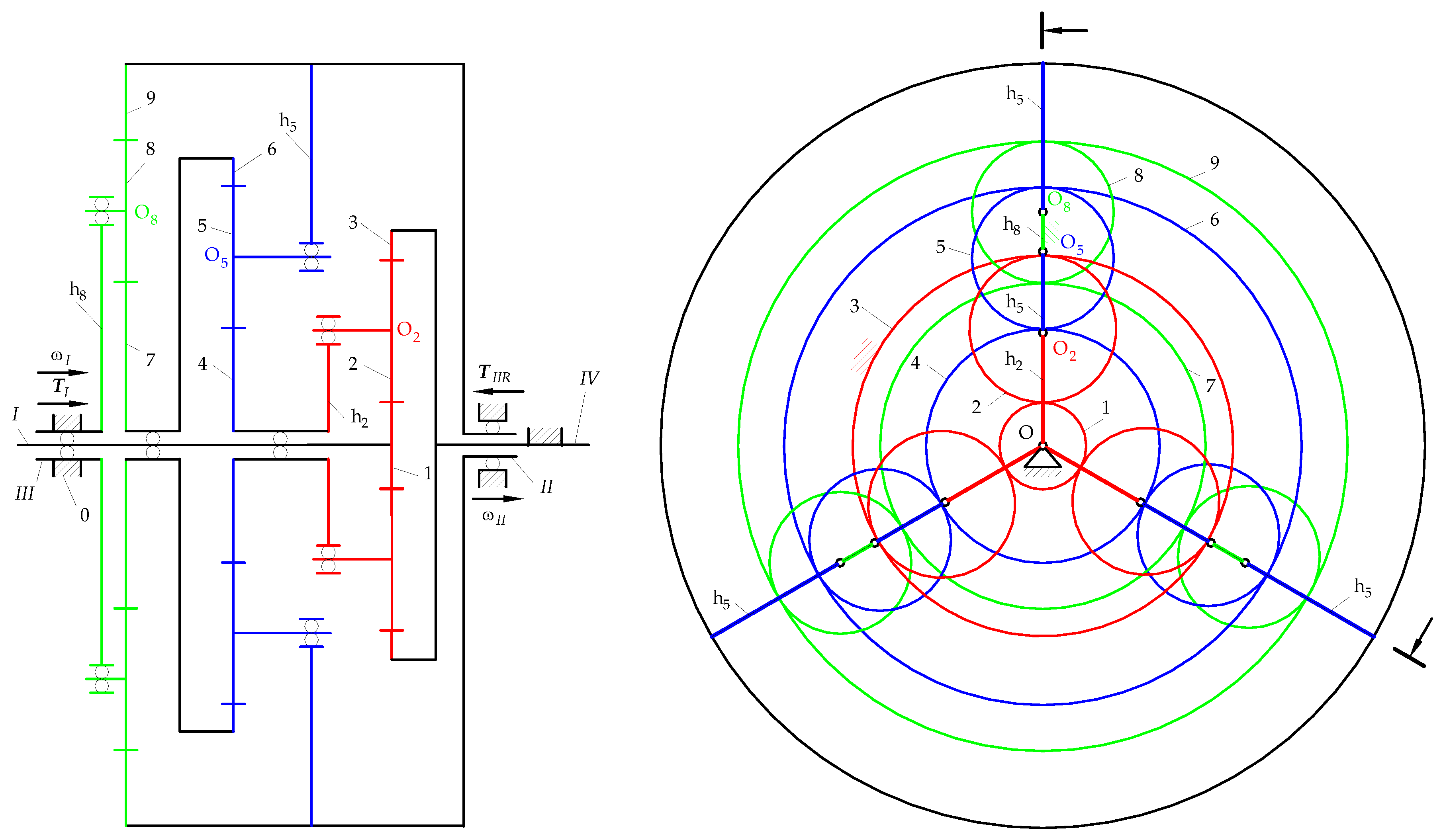
Figure 2.
Figure 2. Diagrams of the analysed PGS: (a) Kinematic; (b) Block.
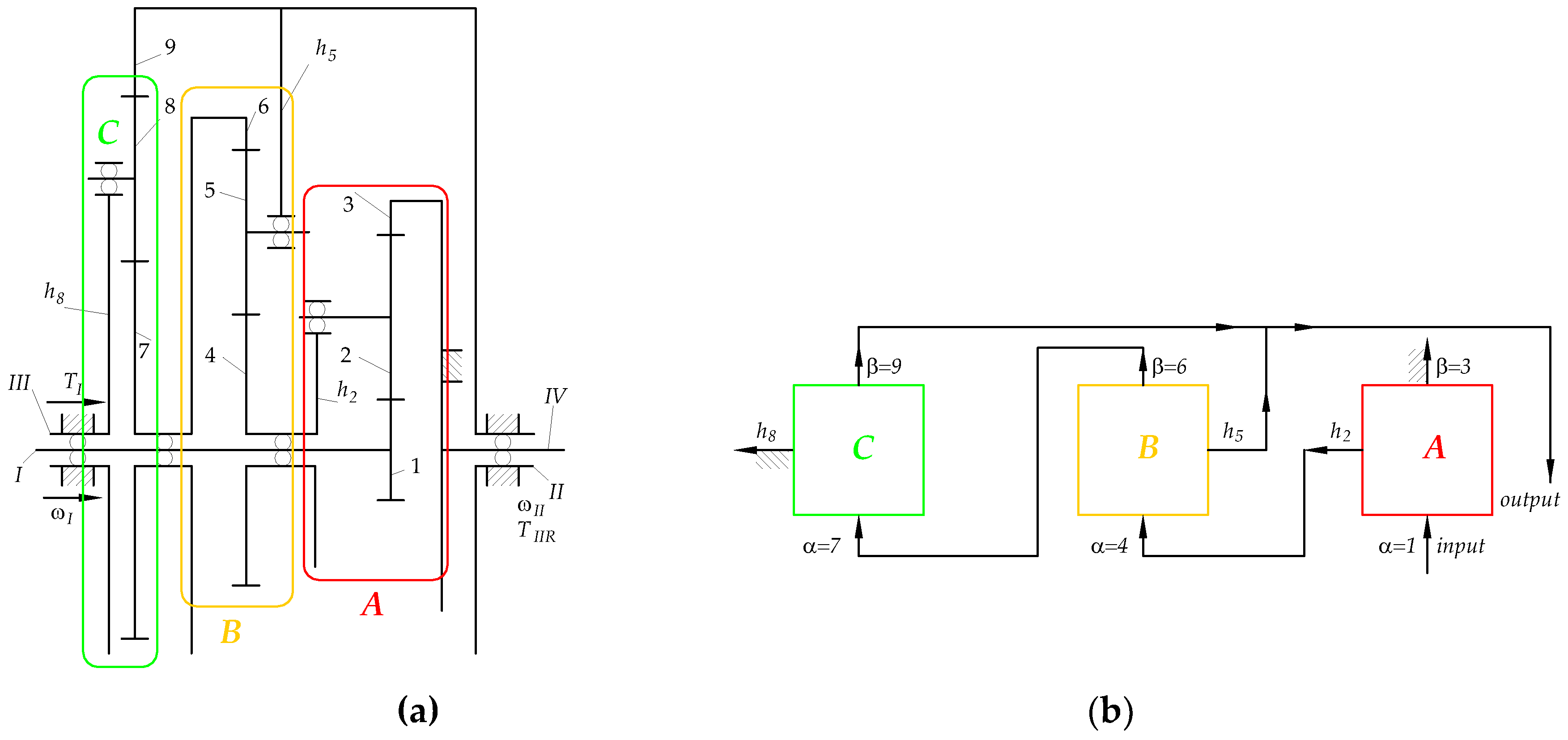
Figure 3.
Block diagrams of possible types of subsystems with single DOF.
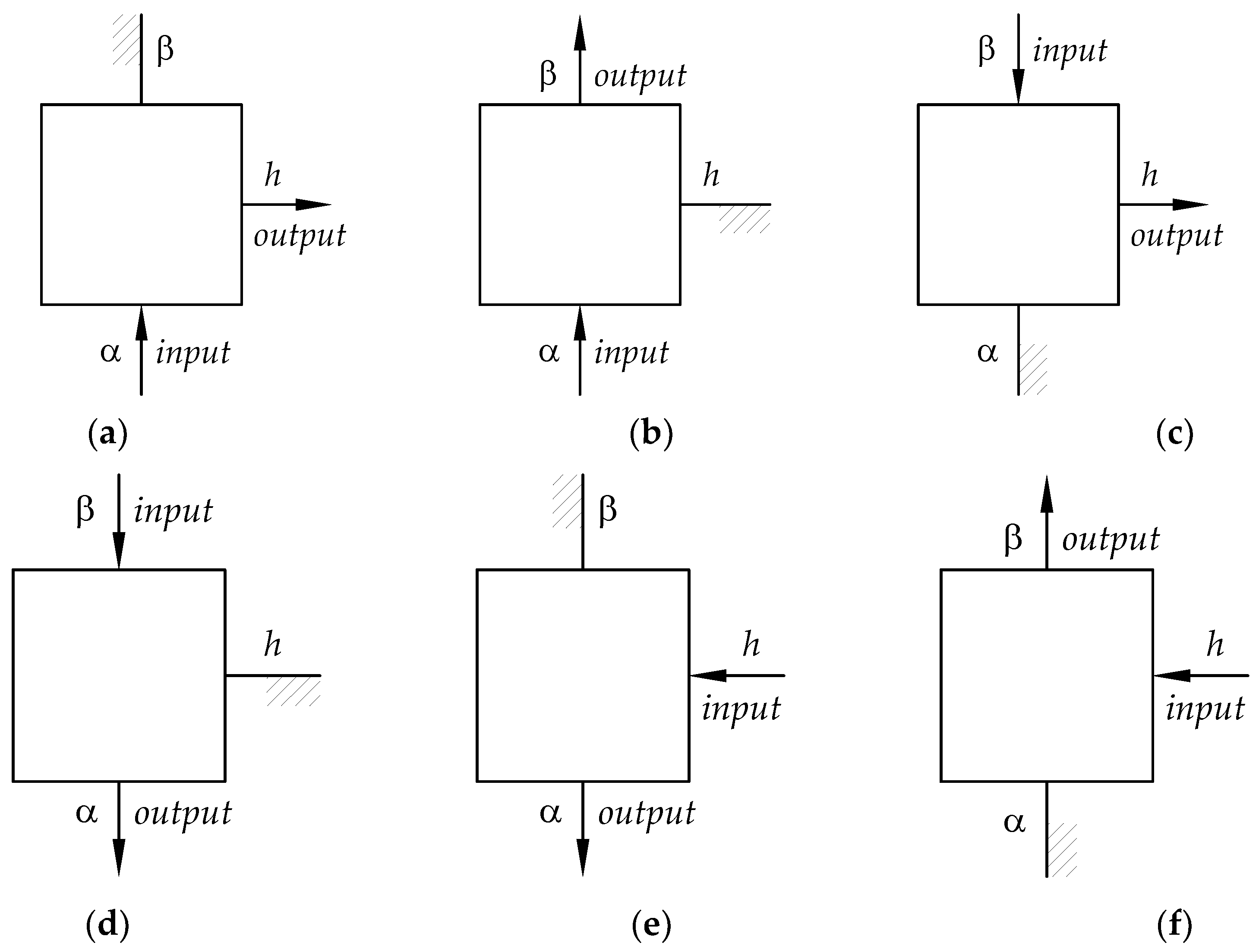
Figure 4.
Block diagrams of possible types of subsystems with two DoF.

Figure 5.
Expanded block diagrams of analysed PGS subsystems (according to Figure 3 and Figure 4): (a) C-type 3(b); (b) B-type 4(a); (c) A-type 3(a).
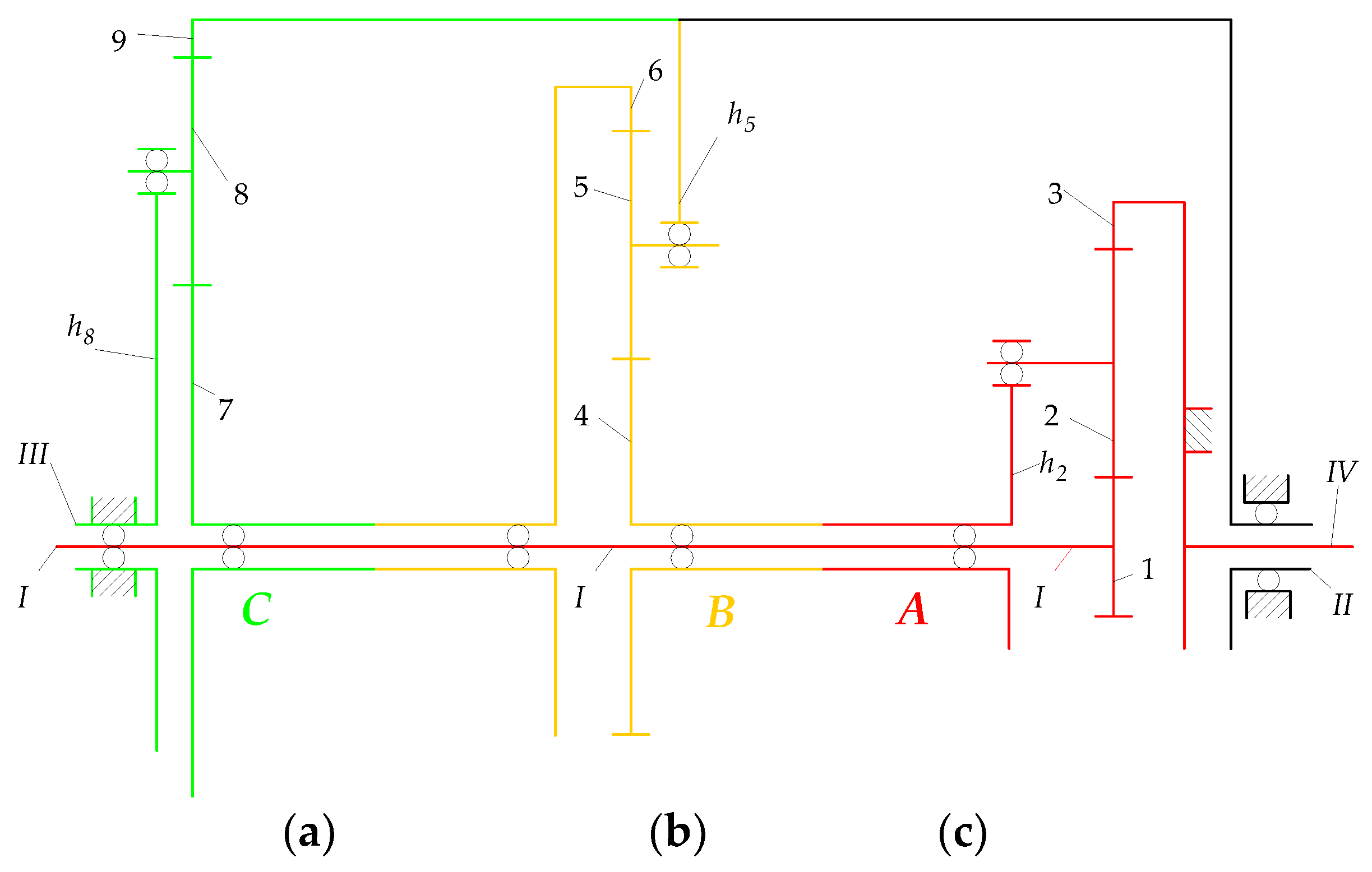
Figure 6.
Angular velocities and torques of: (a) Elements of subsystem A; (b) Pair carrier - sun gear 4.Identification of the power flow paths in types 4(a), 4(e) or 4(f) subsystems B
Figure 6.
Angular velocities and torques of: (a) Elements of subsystem A; (b) Pair carrier - sun gear 4.Identification of the power flow paths in types 4(a), 4(e) or 4(f) subsystems B
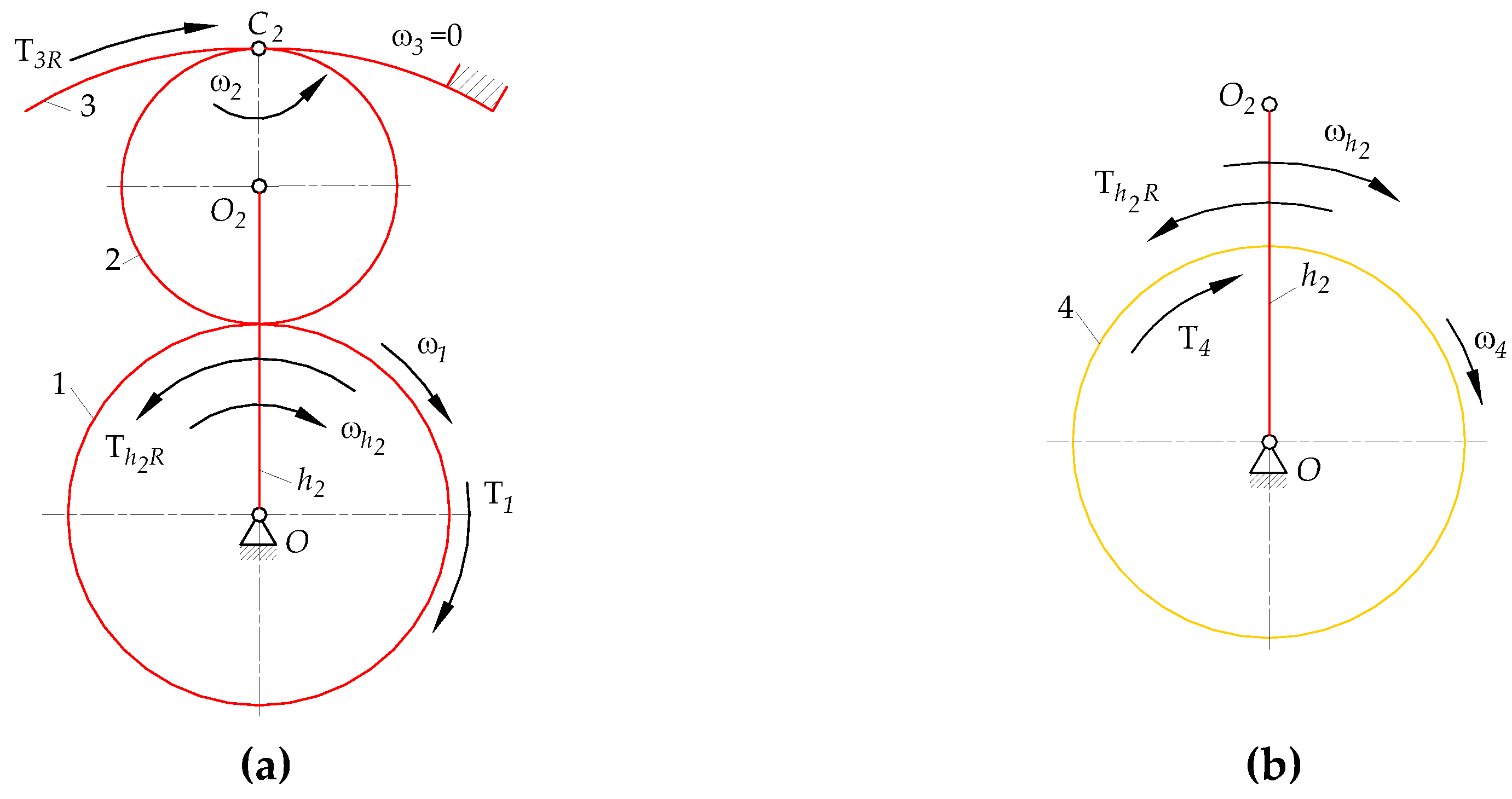
Figure 7.
Angular velocities and torques of: (a) Elements of subsystem B; (b) Gear pair 6, 7.
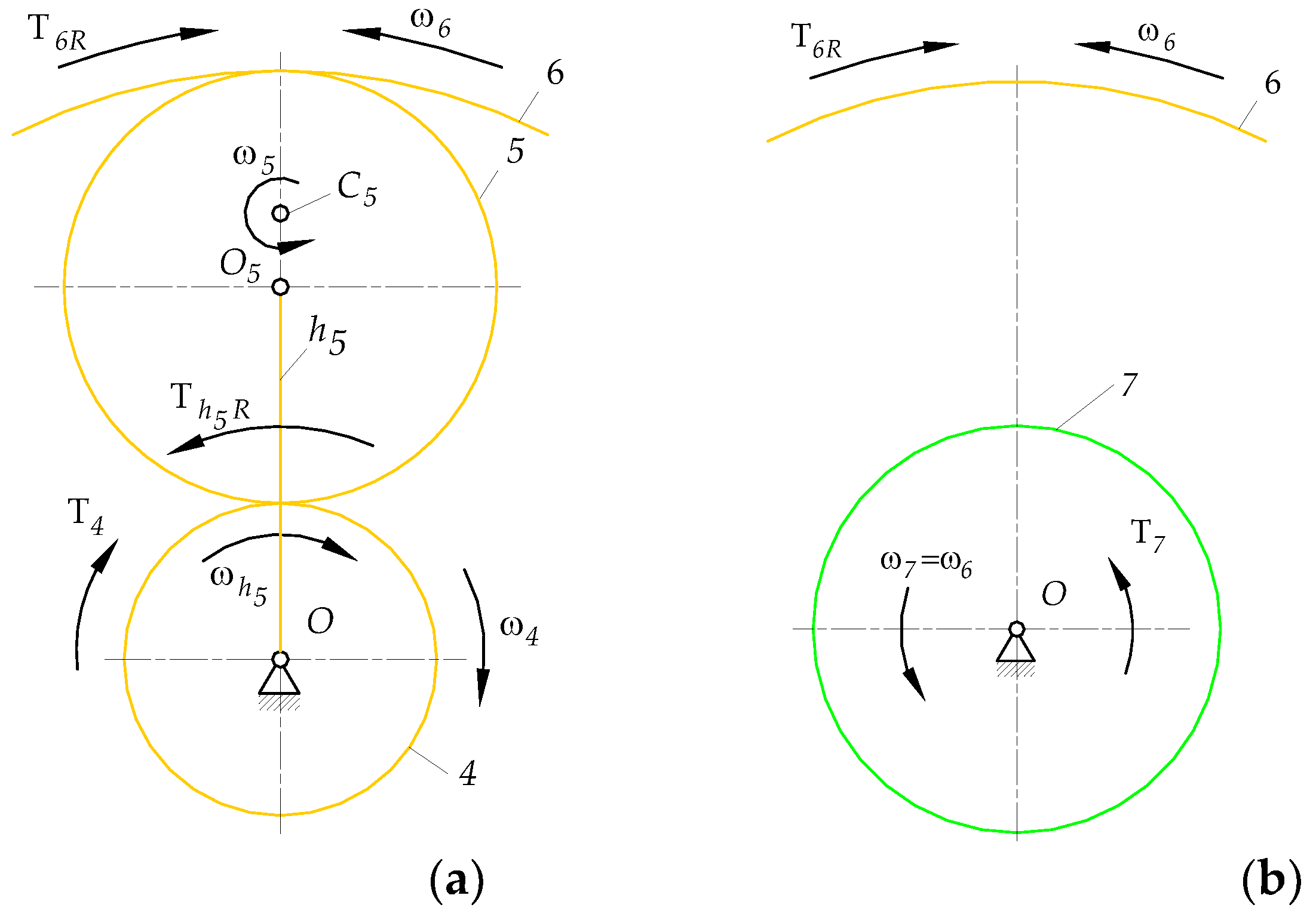
Figure 8.
Figure 8. Angular velocities and torques of C subsystem elements.
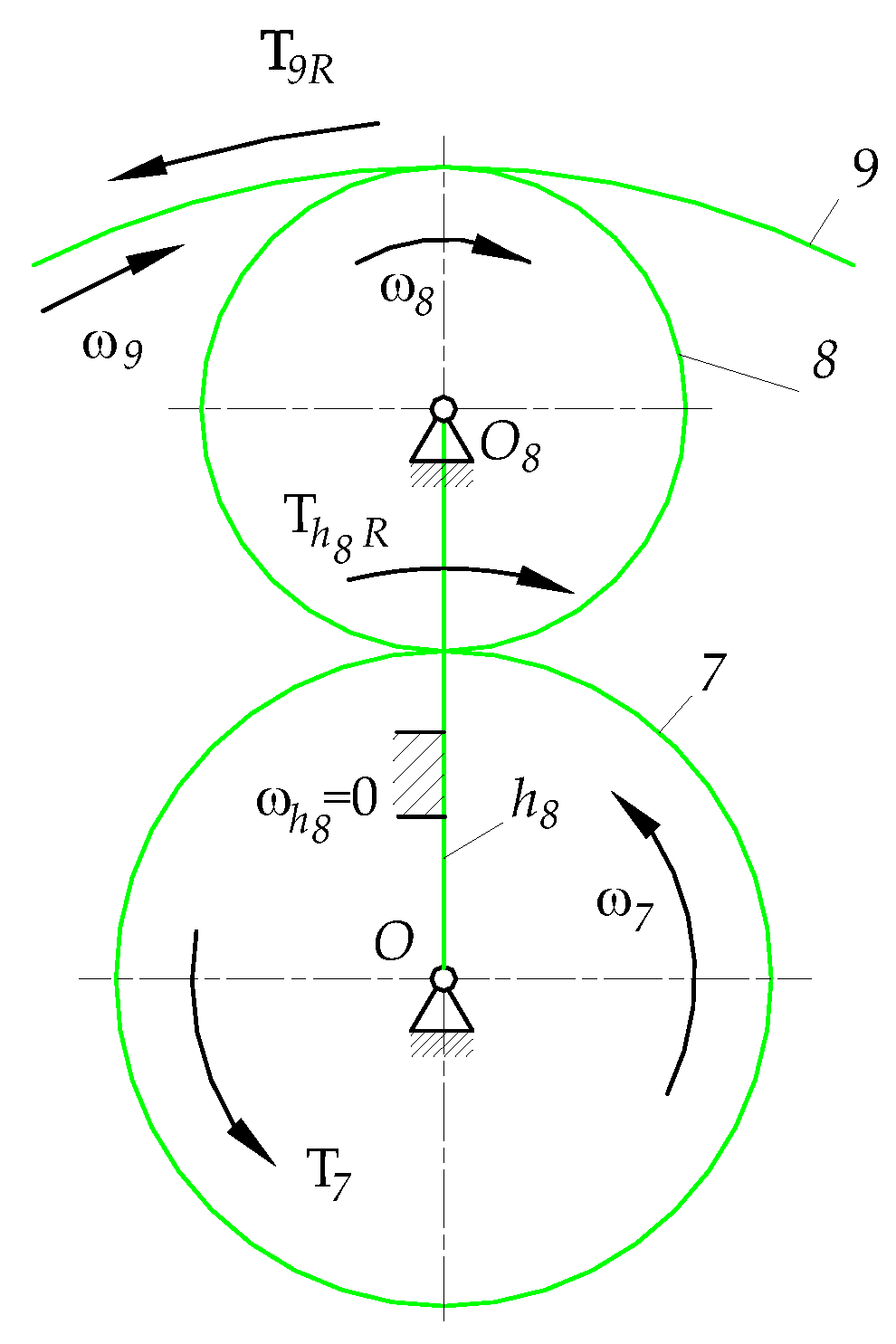
Figure 9.
Directions of power stream flows and power ratios in the: (a) Pseudo-coupled PGS, (b) Coupled PGS [3].
Figure 9.
Directions of power stream flows and power ratios in the: (a) Pseudo-coupled PGS, (b) Coupled PGS [3].
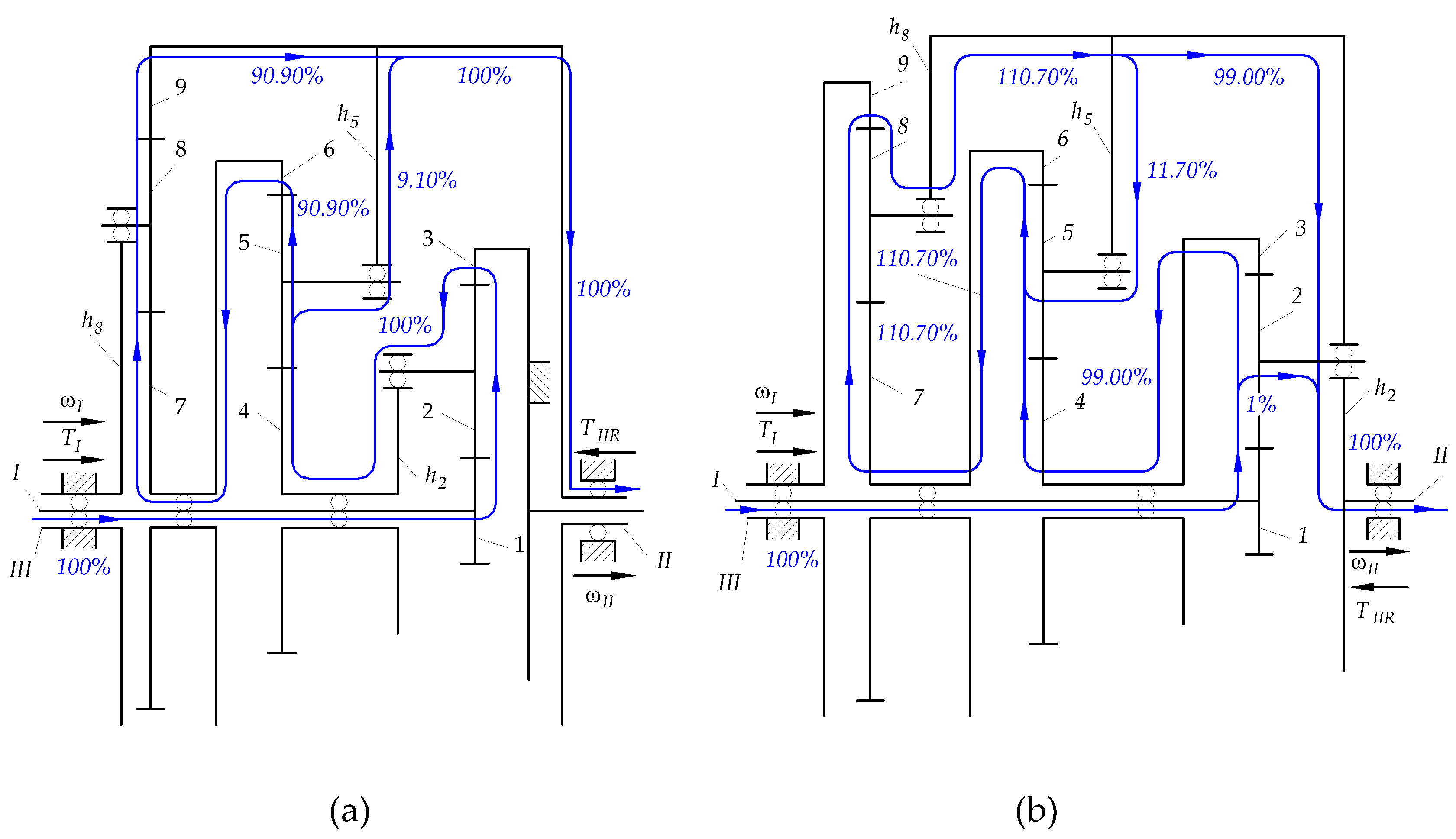
Figure A5.
Balance of active and reaction torques acting on sun gear 4 and carrier , respectively.

Figure A6.
Free body diagrams of the subsystem B elements: (a) Gears 4, 5, 6 (b) Carrier .

| Subsystem | A | B | C |
| DoF Number | 1 | 2 | 1 |
| Subsystem type | 3(a) | 4(a) | 3(b) |
Table 2.
Data on PGS.
| Subsystem A | Subsystem B | Subsystem C | ||||||
|---|---|---|---|---|---|---|---|---|
| ) | ||||||||
Table 3.
Values of fixed carrier transmission ratio of subsystems of analysed PGS and sun and planet gear pairs.
Table 3.
Values of fixed carrier transmission ratio of subsystems of analysed PGS and sun and planet gear pairs.
| -7 | -11 | -3 | -5 |
Table 4.
Vectors of angular velocities of elements of the PGS in .
Table 5.
The transmission ratios on the power flow paths of the subsystems of PGS.
| 8 | 125 | -11.36(36) | 10.25 |
Table 6.
Torque vectors , and , in .
Table 7.
Torque vectors , and , in .
Table 8.
Values of the torques and in .
Table 9.
Active and reactive shafts of the PGS.
| Parameter | Shafts of gear or carrier | ||||||
| 1 | 4 | 6 | 7 | 9 | |||
| Character | Active | Reactive | Active | Reactive | Reactive | Active | Reactive |
| Type | 3(a) | 3(a) | 4(a) | 4(a) | 4a | 3(b) | 3(b) |
Table 10.
Values of active and passive power on the shafts of subsystem A.
Table 11.
Power ratios on the shafts of subsystem A
Table 12.
Values of active and passive power on the shafts of subsystem B
Table 13.
Power ratios on the shafts of subsystem B .
Table 14.
Values of active and reactive power on the shafts of subsystem C
Table 15.
Power ratios on the shafts of subsystem C
Disclaimer/Publisher’s Note: The statements, opinions and data contained in all publications are solely those of the individual author(s) and contributor(s) and not of MDPI and/or the editor(s). MDPI and/or the editor(s) disclaim responsibility for any injury to people or property resulting from any ideas, methods, instructions or products referred to in the content. |
© 2024 by the authors. Licensee MDPI, Basel, Switzerland. This article is an open access article distributed under the terms and conditions of the Creative Commons Attribution (CC BY) license (https://creativecommons.org/licenses/by/4.0/).
Copyright: This open access article is published under a Creative Commons CC BY 4.0 license, which permit the free download, distribution, and reuse, provided that the author and preprint are cited in any reuse.


