
Submitted:
16 May 2024
Posted:
17 May 2024
You are already at the latest version
Abstract
Flexible polymer-based dye-sensitized solar cells (DSSCs) offer promising potential for lightweight, cost-effective and versatile photovoltaic applications. However, the critical challenge in their widespread applications is the weak thermal stability of the majority of polymeric substrates, which can only withstand a maximum temperature processing of 150°C. In this study, we propose a facile and low-cost strategy to develop at low temperature DSSC flexible photoanode based on a polymeric matrix. Highly porous nanocomposites fibrous mats composed of polyethylene terephthalate (PET) and titanium dioxide (TiO2) nanobars were prepared through electrospinning process using different configurations (uniaxial electrospinning, coaxial electrospinning, and electrospray-assisted electrospinning). These techniques enabled precise control of the microstructure and the positioning of TiO2 within the composite nanofibers. Therefore, the as-produced photoanodes were loaded with N719 dye and tested in DSSC prototype using iodide-triiodide electrolyte and platinum (Pt) coated counter electrode. The results show that incorporating TiO2 on the fiber surface through the electrospray-assisted electrospinning enhanced the performance of the nanofiber composite, leading to improved dye loading capacity, electron transfer efficiency and photovoltaic performance.
Keywords:
Electrospinning
; Electrospraying
; Coaxial electrospinning
; Nanocomposites
; Nanofibers
; Flexible DSSCs
; Photoanode
; TiO2
1. Introduction
The growing need for sustainable energy solutions has driven the exploration of innovative technologies to harness renewable resources efficiently. Among these technologies, Dye-sensitized solar cells (DSSCs), classified as third generation of photovoltaic technology, emerge as promising solar cells due to their cost-effectiveness, stability, ease of fabrication and reasonable efficiency in diverse light conditions [1]. DSSCs are primarily composed of three components: photoanode, liquid electrolyte and a catalytic counter electrode [2]. The photoanode layer plays a central role in the cell’s operation, facilitating key processes of light absorption and carrier transportation [3]. Usually, the TiO2 paste is applied to a brittle, rigid substrate coated on fluorine-doped tin oxide (FTO) glass, and then subjected to sintering at high temperatures ranging between 450-500 °C [4]. This thermal treatment is crucial for removing the organic binder, forming pores to facilitate efficient dye absorption, establishing electrical connectivity among TiO2 nanoparticles, as securing a robust electrical contact between the TiO2 layer and the substrate [5]. However, this conventional glass-based DSSCs present several limitations, including their lack of flexibility, fragility, significant weight, shape constraints, elevated cost, and incompatibility with industrial processing (roll-to-roll process)[6]. On the other hand, flexible plastic-based DSSCs offer notable benefits, such as being lightweight, flexible, portable, suitable for mass production, and cost-effective [7]. Moreover, the adoption of flexible plastic substrates broadens the potential applications of DSSCs, accommodating needs in sectors that require flexibility, such as building-integrated devices, wearable technology, and portable electronics [8]. Consequently, there has been push towards the development of flexible DSSCs using plastic substrates.
Developing flexible DSSCs poses significant challenges, primarily due to the limited thermal stability of plastic substrates, which can withstand temperatures up to only 150°C [9]. Various studies have explored the creation of flexible porous TiO2 photoanodes through low-temperature processes such as chemical sintering [10], electrodeposition[11], and mechanical compression [12]. Despite these efforts, these methods often encounter problems such as inadequate interparticle contact, compromised film integrity, and poor adhesion between the TiO2 layer and the plastic substrate [13]. As a result, the TiO2 films frequently develop cracks and are susceptible to detachment during bending, leading to device failure or rapid performance decline[11]. In practical applications, flexible DSSCs undergo repeated mechanical deformation, including bending, rolling, and twisting, making the mechanical stability of the device just as critical as its photovoltaic performance [14].
To tackle the issue and boost the mechanical robustness of flexible DSSCs, considerable research has been dedicated to altering the photoanode structure via the incorporation of polymers [15,16,17,18]. Among these efforts, Li et al. [16] investigated employing Polyvinylidene fluoride (PVDF) nanofibers as a scaffold to incorporate binder-free TiO2 nanoparticles within a flexible DSSC photoanode, utilizing a spray-assisted electrospinning technique. This approach of adding polymer fibers effectively mitigates stress within the photoanode when it's bent, thereby diminishing the risk of delamination by slowing down the initiation and spread of cracks. In a previous work of our research group [18], the authors proposed a low-temperature method to create a Polypropylene (PP)/TiO2 porous flexible photoanode, employing melt extrusion followed by uniaxial stretching. Yet, this technique introduces a balance challenge between the cell's efficiency and its mechanical strength due to the heightened electrical resistance in the photoanode after adding the polymer. Overloading the photoanode with polymer, intended to improve its durability, may inadvertently cover TiO2 particles. This coverage can obstruct dye adsorption and impede electron transport, thus affecting the overall performance of the cell [16].
This study aims to create novel functional PET/TiO2 composite nanofibrous mats using a low-temperature electrospinning technique, and evaluate their effectiveness as flexible photoanodes in DSSC. The electrospun nanofibrous mats, distinguished by their unique porous structures, enhance dye adsorption and facilitate electrolyte diffusion, offering advantages over traditional TiO2 photoanode layer [19]. To construct the flexible, composite fiber-based photoanodes, various methods including uniaxial electrospinning, coaxial electrospinning, and electrospray-assisted electrospinning were employed. These techniques allow for precise control over the nanofibers' microstructure and the selective distribution of TiO2 particles within them. Specifically, by confining TiO2 nanoparticles to the nanofibers' outer layer (the shell) using coaxial electrospinning, or by affixing them to the fibers' surface via electrospray-assisted electrospinning, the study seeks to enhance the interaction between TiO2 and the dye molecules. Such optimization aims to improve light absorption and electron transport efficiency within the DSSC’s photoanode, contributing to the development of more efficient solar cells.
Polyethylene terephthalate (PET) was chosen as the fiber’s matrix owing to its notable structural and mechanical qualities. For achieving superior dispersion within the polymer solution, surfactant-encapsulated TiO2 nanobars (referred to as TiO2,NB) were utilized, replacing the traditional commercial Degussa P25 TiO2. The adoption of one-dimensional (1D) TiO2 is anticipated to establish a direct pathway for electron transport, enhancing rapid charge collection and minimizing recombination events [20]. To the best of our knowledge, this is the first time for such structure to be used as flexible photoanodes in DSSC applications.
2. Materials and Methods
2.1. Materials
The following chemicals were used in this work as received without further purification. Titanium (IV) butoxide (TB, 97%), oleic acid (OA, 90%), oleylamine (OM, 70%), absolute ethanol and toluene (analytical grade) were purchased from Sigma Aldrich, Canada. Polyethylene terephthalate (PET) pellets (Laser + C9921) were purchased from DAK Americas, USA. Electrospinning/Electrospray solvents, trifluoroacetic acid (TFA) and dichloromethane (DCM), which were all analytical grade, were respectively supplied from Alfa AESAR, and Acros Organic, Canada. N719 industry standard dye Di-tetrabutylammonium cis-bis(isothiocyanato)bis(2,2′-bipyridyl-4,4′ dicarboxylato)ruthenium(II)) was purchased from Fisher Scientific, Canada. Indium tin oxide/polyethylene terephthalate substrate (ITO/PET, thickness of 175 µm, 20-30 Ω sq-1) was provided by MSE Suppliers, USA. Platinum-coated fluorine doped tin oxide glass counter electrode (Pt-FTO/glass) and Iodolyte AN-50 high performance electrolyte (Iodide based) were purchased from Solaronix, Switzerland.
2.2. Synthesis of TiO2,NB
The synthesis of TiO2,NB was conducted via a solvothermal method, in the presence of OA and OM as capping agents, as previously described in our work [21]. Initially, 1 mmol of TB was mixed with 6 mmol of OA and 4 mmol of OM. This mixture was then stirred for 15 min, after which 1 ml of absolute ethanol was added, followed by another 15 min of stirring. The mixture was then placed inside a Teflon cup, which was subsequently transferred to a Teflon-lined stainless-steel autoclave filled with 4 ml of ethanol 95%. The autoclave was heated inside an oven at 150 °C for 18h. Upon cooling to room temperature, the resulting TiO2 nanoparticles, appearing as white solid precipitate powder), were collected by vacuum filtration and washed at least four times with ethanol and toluene. The final product was left to dry at room temperature for 24 h.
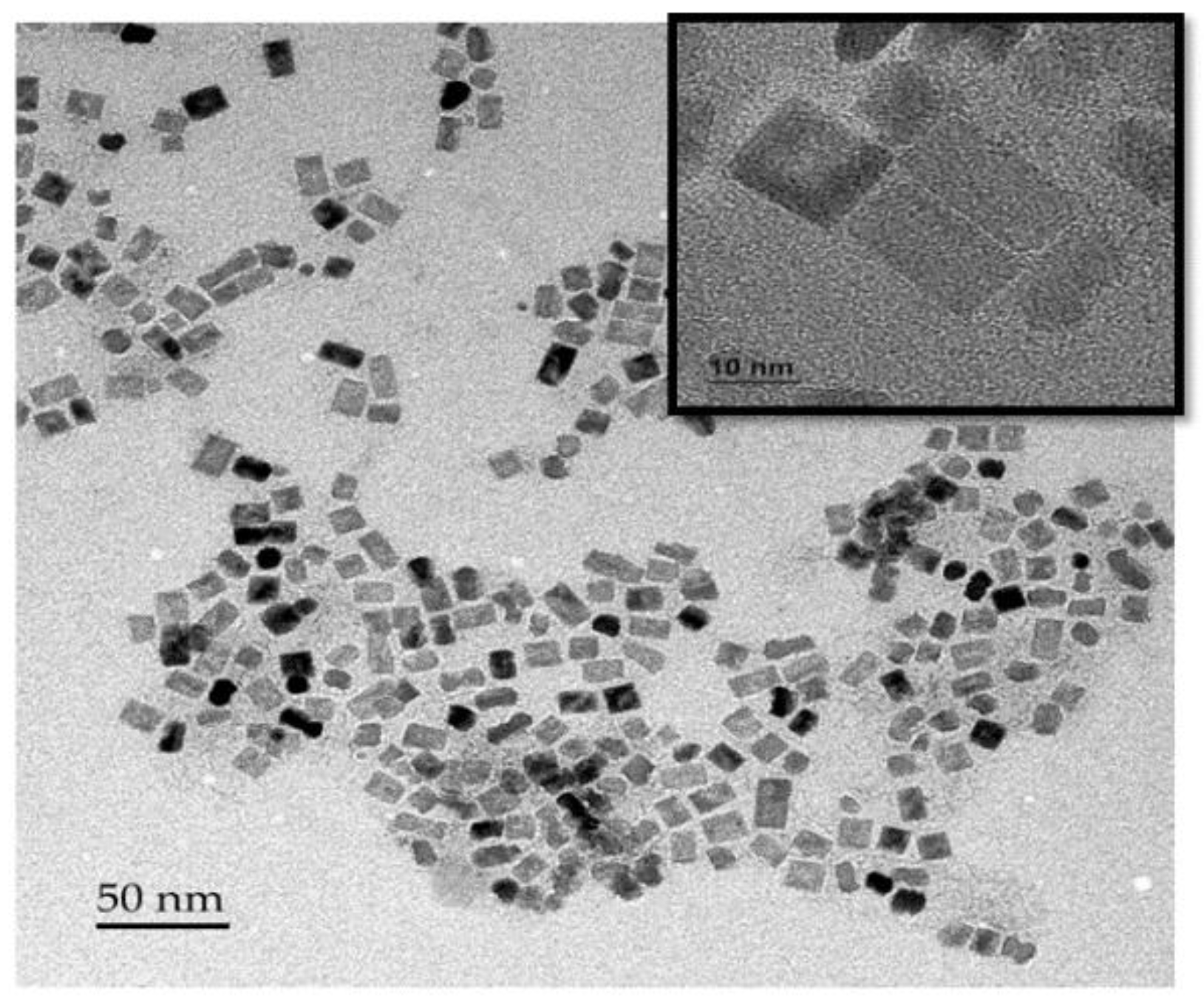
Figure 1.
TEM image of surfactant-capped TiO2,NB used in this work [21].
Figure 1.
TEM image of surfactant-capped TiO2,NB used in this work [21].
2.3. Development at Low Temperature of Composite Fiber-Based DSSC Photoanode Layer
Well-dispersed electrospinning solutions of PET and PET/TiO2,NB were prepared by initially dissolving 1.5 gr of PET in 10 ml mixture of TFA/ DCM (70/30 v/v) mixture, stirring for 18 hours to ensure the PET was completely dissolved. For PET-TiO2 solutions, TiO2,NB were incorporated into the polymer solution at a concentration of 15 wt.% relative to PET. The resulting mixture was then stirred for an additional 18 hours, followed by 2 hours of sonication at room temperature to ensure the TiO2 nanoparticles were homogeneously dispersed. Immediately before the electrospinning process, each solution underwent an additional 5 minutes of sonication to prevent nanoparticles agglomeration. For the electrospray solution, 7 wt. % of TiO2,NB was dispersed in the solvent by stirring for 3 hours and then sonicated for 15 minutes to achieve a well-dispersed mixture.
Flexible composite fiber-based photoanodes were developed using three distinct methods: uniaxial electrospinning (UE), coaxial electrospinning (CE), and a combined electrospinning/electrospray process (E-ES). The schematic diagrams of these fabrication techniques are depicted in Figure 2. To create the electrospun fibrous mats, we used a home-made laboratory-scale electrospinning setup. This setup consisted of two programmable syringe pumps (Pump 11 Elite by Harvard Instrument, USA, and NE-300 by Era Pump Systems Inc, USA), a high-voltage power supply (Chargemaster CM60-P by Simco, USA), and a grounded collector plate covered with aluminum foil. The aluminum foil was affixed to a 2 cm x 2 cm section of a transparent, conducting ITO-coated PET film, facilitating the direct deposition of the composite fibers onto the substrate.
In the Uniaxial Electrospinning process, PET/TiO2,NB nanofibrous mats were fabricated by electrospinning a singular solution comprising PET and TiO2,NB nanoparticles. Conversely, the Coaxial Electrospinning process utilized two distinct solutions: one of PET for the core and another of PET/TiO2,NB for the shell. Detailed methodologies of the UE and CE processes are extensively documented in our work [20,21]. In the Electrospinning-Electrospraying process, a PET solution was electrospun to form a PET nanofiber matrix, while concurrently, a TiO2,NB solution was electrosprayed onto the surface of the resulting mats. The operational parameters for each method are concisely outlined in Table 1.
2.4. DSSC Device Assembly
The production process of the DSSC device comprises multiple phases. Initially, the prepared photoanodes are submerged in a 0.3 mM solution of N719 dye dissolved in ethanol for 48 hours at ambient temperature. After this period, the photoanodes are meticulously extracted from the dye solution and then washed with ethanol to eliminate any remaining dye that was not absorbed. Following this cleaning step, they are allowed to air dry in preparation for the assembly phase. The counter electrodes, which are Pt-coated FTO glass, were pre-treated with platinum and had pre-made holes for this experiment. Before incorporation into the cell, the components were washed with ethanol and subsequently subjected to heat treatment in a furnace at 450 °C for 20 minutes. This step is crucial for reactivating the catalytic Pt layer, thereby maximizing its performance. The assembly of the DSSC followed, arranged in a sandwich structure with the conductive sides of the electrodes facing inward towards each other. To prevent electrolyte evaporation and leakage, a 25 µm hot-melt Surlyn gasket served as the sealing agent. Heat and pressure were uniformly applied until the gasket achieved full adhesion to both electrodes.
Finally, the cell was filled with iodide-triiodide electrolyte through the pre-prepared hole in the counter electrode, using a vacuum-fill syringe. To finalize the assembly and ensure it was sealed, any excess electrolyte on the cell was carefully removed, and the holes were then covered with thin glass caps. These were sealed in place using a Surlyn sheet, which was bonded to the surface through resistive heating.
2.5. Dye Adsorption Characterization
Effective dye incorporation between the photoanode and the dye is crucial for the optimal performance of the DSSC. To measure dye loading, the dye is desorbed from the surface of the electrospun fibers by immersing them in a 0.1 M NaOH solution for 90 seconds. Initially, the nanofibrous mats are soaked in a 0.03 mM N719 dye solution in absolute ethanol for 48 hours, followed by rinsing with absolute ethanol to eliminate any unbound dye, and then air-dried at ambient temperature. The dye desorbed into the NaOH solution is then quantitatively analyzed through its optical absorption spectra using a UV-visible spectrophotometer (Carry 7000 model, Agilent, USA).
To provide a quantitative comparison of dye loading of the mat samples developed in this study, dye loading was estimated by the following equation [22]:
where C (mol/L) is the concentration of adsorbed dye, V (L) the volume of the desorbed solution and S (cm2) the active area of the nanofibrous mats (S=0.25 cm2 in this study). The concentration C of adsorbed dye was calculated by using the Lambert-Beer equation [23]:
where A is the UV-Vis absorbance peak intensity at 505 nm, M-1 cm-1 is the molar extinction coefficient of N719 dye and l= 1 cm is the length of the optical path.
2.6. DSSC Photovoltaic Performance Characterization
The current-voltage (I-V) measurements were performed using a Keithley model 2400 digital source meter, interfaced with SciRunIV software for data acquisition. To simulate sunlight irradiation, a ScienceTech Xe solar cell simulator, with an AM1.5 G spectrum, was used. The light intensity was calibration was achieved using a crystalline silicone (c-Si) as the reference cell. For photovoltaic performance evaluation, the DSSC devices were shielded with a black mask defining an active area of 0.25 cm2. The fill factor (FF) and power conversion efficiency (PCE) were derived from the I-V curve using the following equations:
where Imax is the maximum current density, Vmax the maximum voltage generated at the maximum power point, Pmax. JSC is the short circuit current density, VOC is the open circuit voltage obtained by the DSSC under sunlight irradiation. Pin is the power of the sunlight illumination.
2.7. Electrochemical Impedance Spectroscopy (EIS) Characterization
In order to investigate the characteristics of the photoanode/dye/electrolyte interface and electron transport properties, an EIS analysis was carried out. This was performed using a Palmsens4 potentiostat (Bioanalytical Systems Inc., USA). The EIS experiments were conducted under a light irradiation intensity of 100 mW/cm2, using a 150 W xenon arc lamp (ABET Technologies, Light Source LS 150). The frequency range for the measurements was established from 0.1 Hz to 100 kHz, with a 10 mV amplitude. The data gathered from the EIS study were then analyzed using ZView software for detailed insights into the electrochemical properties.
3. Results
3.1. Morphology Characterization of the Developed Nanofibrous Photoanode Mats
In this study, we developed various flexible nanofibrous photoanodes by integrating TiO2,NB into the PET fiber framework using the three methods (UE, CE and E-ES) described above in section 2.3. The surface morphology of the newly prepared photoanodes was assessed through Scanning Electron Microscopy (SEM) analysis and the corresponding images are shown in Figure 3. The SEM images reveal that the nanofibrous photoanode mats developed via UE and CE methods exhibit similar morphologies. Both types of photoanodes demonstrate a homogeneous porous structure characterized by bead-free and randomly oriented nanofibers. The distribution of TiO2 nanoparticles within the electrospun fibers prepared through both uniaxial and coaxial electrospinning methods has been elaborated on in our prior studies [20,21]. In the uniaxial electrospinning (UE), TiO2 nanoparticles predominantly scatter randomly within the PET fibers, with a considerable amount being enveloped by the PET polymer. Conversely, the coaxial electrospinning (CE) facilitates a more surface-oriented embedding of TiO2 nanoparticles on the nanofibers, leading to the formation of a distinct core-shell structure, rather than being dispersed throughout the fiber. This is depicted in the inset of image (b) in Figure 3, showcasing the unique arrangement. On the other hand, the electrospinning-electrospraying (E-ES) method yields a noticeably different morphology. The electrosprayed TiO2 nanoparticles are clearly present on the surface of the PET fibers, as evidenced by the SEM images (c) and (d). To further verify the surface deposition of TiO2 on the fibers, energy dispersive X-ray (EDX) analysis was conducted, the results of which are presented in image (e) of Figure 3. EDX spectra confirmed the presence Ti element. For samples developed by E-ES, TiO2 nanoparticles were deposited on the fiber surfaces as small spherical aggregates, thereby increasing the surface roughness. This effect is primarily attributed to the use of highly volatile chloroform solvent [24]. Additionally, the porous network revealed micropores filled with TiO2 nanoparticles interspersed among the fibers.
3.2. Dye Adsorption on the Surface of Nanofibrous Photoanode Mats
Dye adsorption entails the attachment of light-absorbing dye molecules to the photoanode's surface, a key process that significantly affects the DSSC's efficiency in transforming sunlight into electrical energy. To assess the dye adsorption capacity of the flexible nanofibrous photoanodes fabricated via the three methods (UE, CE, and E-ES), the photoanode mats were submerged in an N719 dye solution for 48 hours. Subsequently, the dye anchored to the surface of the electrospun fibers was desorbed using a NaOH basic solution. The absorption curves in the UV-visible spectrum for the desorbed N719 dye were meticulously analyzed and juxtaposed. Figure 4 (a) and (b) starkly highlights the significant variations in dye adsorption capabilities across the developed nanofibrous mats. Notably, the PET-TiO2 mats, synthesized via the electrospinning-electrospraying (E-ES) method, demonstrated a dramatic enhancement in N719 dye adsorption efficiency, recording increases of 110% and 337% when compared to coaxial electrospun (CE) PET/PET-TiO2 core/shell mats, and uniaxial electrospun (UE) PET/TiO2 mats, respectively. Despite the reduced porosity observed in the E-ES process compared to UE and CE processes, owing to the occlusion of micropores by TiO2 agglomerates (as illustrated in Figure 2), the microstructural outcome presents a notable benefit. The E-ES process leads to a greater exposure of TiO2 nanoparticles on the fiber surface along with enhanced surface roughness. This modification significantly boosts the adsorption capacity for N719 dye molecules, as evidenced by Ahmad et al. [25]. During the dye loading phase, a portion of the dye molecules becomes chemically bonded to the surface of the TiO2 nanoparticles, whereas others migrate into the porous framework of the nanofibrous mats [26]. For the mats developed by UE method, the random arrangement of TiO2 inside the fibers, potentially concealed by the PET polymer, hinders the entry and adsorption of dye molecules, leading to a decrease in dye loading efficiency. These findings align closely with the outcomes of morphological examinations presented above in section 3.1.
3.3. Current-Voltage (J-V) Characterization
The evaluation of the performance of the developed flexible nanofibrous photoanodes in a DSSC prototype was carried out by recording J-V curves under simulated solar irradiation, with the results presented in Figure 5. The DSSC performance parameters, including open-circuit voltage (Voc), short-circuit current density (Jsc), fill factor (FF), and power conversion efficiency (η), derived from these plots, are compiled in Table 2. It is evident that the electrospinning-electrospraying method, which involves the decoration of PET nanofibers with TiO2 nanoparticles, achieves the highest power conversion efficiency η at 0.03%. This is followed by coaxial electrospinning (CE) with an efficiency of 0.01%, while uniaxial electrospinning (UE) shows considerably poorer performance, resulting in significantly lower efficiency. The increased efficiency primarily stemmed from a notably higher Jsc. Table 2 demonstrates that the PET/TiO2-decorated nanofiber-based photoanode, produced via the E-ES method, exhibited a current density of 0.12 mA/cm². This signifies a substantial 200% enhancement relative to the PET/PET-TiO2 core-shell nanofiber-based photoanode, which had a current density of 0.04 mA/cm². Furthermore, a significant difference in Jsc was noted for the photoanode obtained with the UE method generating a current density two orders of magnitude lower than that of the CE method, despite both processes utilizing the same concentration of TiO2 nanoparticles.
The decrease in Jsc suggests that fewer TiO2 nanoparticles participated in the electron injection process, leading to a decreased light harvesting efficiency in DSSCs [27]. This finding underscores the vital importance of the strategic placement of TiO2 nanoparticles on the nanofiber's surface to boost photovoltaic performance. Enhancements in Jsc are primarily driven by two factors: an increase in dye adsorption and a reduction in charge recombination [28]. For samples developed by the uniaxial electrospinning (UE) method, the TiO2 nanoparticles were dispersed randomly within the fiber and encapsulated by the PET polymer, which obstructed the adsorption of dye molecules and hindered their access.
PET's insulating nature impedes the flow of electrical charges, diminishing its photovoltaic efficiency. Conversely, the coelectrospinning (CE) method enables the positioning of TiO2 nanoparticles on the outer layer (fiber shell), increasing the PET-free surface area available to these nanoparticles. This enhancement allows for better access to dye molecules, thereby improving dye adsorption and elevating the short-circuit current density (Jsc). In the electrospinning-electrospraying (E-ES) method, a marked improvement in dye loading was observed, attributed to the greater presence of TiO2 nanoparticles on the PET nanofiber surface. This increase in dye/TiO2 interaction boosts the electron injection rate and their transfer to the external circuit, leading to a higher Jsc [29]. Moreover, the open-circuit voltage (Voc) and fill factor (FF) displayed no significant variation between the samples developed by both CE and E-ES methods. However, both parameters experienced notable declines for photoelectrodes developed using the UE method. The Voc, which is largely determined by the energy gap between the Fermi level of TiO2 and the electrolyte's redox potential, suffers when increased charge recombination occurs [30], as observed in this study. This implies that with TiO2 nanoparticles positioned inside the fiber developed by the UE method, more electrons are diverted through non-productive paths rather than contributing to current generation. Also, the FF, indicative of cell performance quality, saw a significant drop, pointing to reduced conductivity and a rise in the device's series resistance [31].
Most research on flexible electrodes has primarily focused on depositing a pure TiO2 layer onto flexible substrates using low-temperature techniques or incorporating minor polymer quantities into the electrode structure, which has resulted in higher efficiencies compared to our study [32,33]. To the best of our knowledge, the use of polymeric photoanodes is infrequently reported, and their efficiencies are not well documented. For instance, the work of Sa’adah et al. [17] evaluated a Polyacrylonitrile (PAN)/TiO2 porous structure-based photoanode created through an electrospinning process and annealed on FTO/glass at 200°C. The corresponding cells produced nanoampere-level photocurrents, with the most efficient cell reaching 365 nA, cell efficiency range was not discussed in their study. A significant limitation of this study was its restricted flexibility; the high processing temperature made it unsuitable for use on ITO/PET substrates. In previous research by our group [18,34], a polypropylene (PP)/TiO2 porous and flexible thin film was prepared using melt extrusion followed by uniaxial stretching. This material served as a flexible photoelectrode for DSSCs. The photoanodes exhibited a relatively low porosity of approximately 50%, which limited the dye-loading capacity. The highest-performing cell from this earlier study achieved a short-circuit current density (Jsc) of only 0.7 μA/cm2, which is significantly lower than the results of the current study by at least two orders of magnitude. Additionally, the open-circuit voltage (Voc) did not exceed 0.12 V. In our current work, the Voc has been enhanced by approximately four fold. Another study [35] explored one-dimensional TiO2 nanorods-based photoanodes on flexible Ti foil, achieving a Jsc of 0.14 mA/cm2, a Voc of 0.45 V, and an efficiency (η) of 0.03%, closely mirroring our results. However, the significantly higher cost of Ti foil compared to ITO/PET raises concerns regarding its commercial viability.
In this study, a significant challenge encountered during the fabrication of DSSC prototypes was the delamination of the electrospun layer from the ITO/PET substrate. Strong mechanical adhesion is critical to establish effective electrical contact between the semiconductor layer and the substrate, which is essential for high current generation. Enhancing adhesion would not only improve flexibility but also prevent damage to the photoelectrode layer. This issue might be addressed through alternative pre-treatment or post-treatment methods designed to strengthen the adhesion of the mats, thereby enhancing the overall efficiency of the cells.
3.4. Electrochemical Impedance Spectroscopy (EIS) Characterization
An EIS study was carried out on DSSC prototypes to delve deeper into the electron recombination and electron transfer dynamics at the photoanode/dye/electrolyte interface. The Nyquist plots derived from the DSSCs, which were fabricated using flexible nanofibrous photoanode mats developed using CE and E-ES methods, along with their equivalent electrical circuits, are depicted in Figure 6. Table 2 lists the series resistance (Rs) and charge-transfer resistance (Rct) values determined from the fitting. In the electrochemical impedance spectrum, three distinct semicircular regions are typically observed: at low frequencies, the impedance characterizes the Warburg diffusion of the I3-/I- redox couple within the electrolyte; at high frequencies, it reflects the charge transfer at the platinum counter electrode; and the semicircle at mid-frequencies indicates the charge transfer occurring at the interfaces between the photoanode, N719 dye, and electrolyte [36]. A larger semicircle diameter in this mid-frequency region suggests a higher charge transfer resistance (Rct) [37]. In this study, the absence of the low-frequency semicircle can be attributed to the high porosity of the photoanode and the low viscosity of the electrolyte, which enhance ionic diffusion. This observation aligns with findings reported in the literature [38]. A comparison of the Nyquist plots indicates an enhancement in charge transfer at the photoanode/N719 dye/electrolyte interface for the DSSC prototype with the photoanode developed by the E-ES method. As shown in Figure 6, the corresponding Nyquist plot exhibits a smaller semicircle within the medium frequency range compared to that corresponding to the DSSC prototype with the photoanode developed via the CE method, signifying a reduction in charge transfer resistance. This suggests that the positioning of TiO2 nanoparticles on the fiber's surface contributes to a higher density of injected electrons with a lower recombination rate, leading to an increase in the short-circuit current density (Jsc) [39]. Additionally, R1 or Rs in the equivalent circuit represents series resistance, identified as the origin of the first semicircle in the Nyquist plot. This component is linked to the sheet resistance of the conductive substrate, electrolyte resistance, and electrical contacts between TiO2 nanoparticles and the conductive substrate [40,41]. Both photoanodes developed by CE and E-ES methods exhibit high Rs values, aligning with findings in the literature for scenarios utilizing flexible ITO/PET substrates and low-temperature processes [42,43]. Such outcomes are ascribed to the elevated sheet resistance of ITO/PET combined with the lack of high sintering temperatures, which results in inadequate electrical contact between the composite's porous structure and the substrate.
5. Conclusions
A straightforward and cost-effective electrospinning method was employed to fabricate PET/TiO2 nanocomposites at low temperatures, aiming to assess their efficacy as flexible fibrous photoanodes in Dye-Sensitized Solar Cells (DSSCs). TiO2 nanobars were incorporated into the composite PET fibers through three electrospinning techniques (uniaxial electrospinning, coaxial electrospinning, and electrospinning-electrospraying), to meticulously manage their distribution within the composites. Our findings clearly demonstrate that, despite the fact that the mats developed by coelectrospinning (CE) show an improvement compared to those obtained via the method of uniaxial (UE) electrospinning, electrospinning-electrospraying (E-ES) method stands out for its potential in enhancing composite quality and performance compared to the other two techniques explored. SEM images have provided clear evidence of a greater concentration of TiO2 nanoparticles present on the surface of the PET nanofibers developed by E-ES method, a finding supported by EDX analysis. Consequently, the N719 dye adsorption capacity was improved by 110% and 337% in comparison to the PET/PET-TiO2 core-shell nanofiber-based photoanode developed by both CE and UE methods, respectively. Furthermore, photovoltaic characterization has revealed that the short-circuit current density (Jsc) of DSSC prototypes with PET-TiO2 photoanodes developed using the E-ES method saw a 200% increase over the coelectrospun PET/PET-TiO2 core-shell nanofiberous photoanode developed using the CE method, leading to a substantial improvement in energy conversion efficiency. These findings underscore the critical role of TiO2 nanoparticle positioning on the nanofiber surface in enhancing the performance of flexible PET/TiO2 fibrous photoanodes. By making more TiO2 nanoparticles accessible on the surface, N719 dye molecules have easier access, resulting in increased dye adsorption and, consequently, a higher Jsc.
Author Contributions
Hajer Gallah: Conceptualization, Data curation, Formal analysis, Investigation, Methodology, Writing – original draft. Frej Mighri: Conceptualization, Investigation, Resources, Supervision, Validation, Writing – review & editing. Abdellah Ajji: Conceptualization, Investigation, Resources, Supervision, Validation, Writing – review & editing. Jayita Bandyopadhyay: Conceptualization, Investigation, Resources, Supervision, Validation, Writing – review & editing. Nouceir Ahmed Ben Ghorbel: Data curation, Formal analysis, Investigation, Methodology. Judith Castillo-Rodriguez: Conceptualization, Data curation, Formal analysis, Investigation, Methodology,.
Funding
Main funding was received from the Natural Sciences and Engineering Research Council of Canada (NSERC), grants no. RGPIN-2018-04084.
Data Availability Statement
Data will be made available on request.
Acknowledgments
The authors are grateful to the Natural Sciences and Engineering Research Council of Canada (NSERC), as well as the Research Center for High Performance Polymer and Composite Systems (CREPEC) for their financial support of this research. They also extend their thanks to Professor Bryan Koivisto from Toronto Metropolitan University for his assistance in DSSC prototype characterization.
Conflicts of Interest
The authors declare no conflicts of interest.
References
- Naik, P.; Abdellah, I.M.; Abdel-Shakour, M.; Su, R.; Keremane, K.S.; El-Shafei, A.; Adhikari, A.V. Improvement in performance of N3 sensitized DSSCs with structurally simple aniline based organic co-sensitizers. Sol Energy 2018, 174, 999–1007. [Google Scholar] [CrossRef]
- Aziz, N.; Rahman, M.; Umar, A. Comparative study of dye-sensitized solar cell utilizing selenium and palladium cathode. J Indian Chem Soc 2022, 99, 100289. [Google Scholar] [CrossRef]
- Zhang, P.; Chu, F.; Zhou, M.; Tao, B.; Miao, F. DSSC using natural dye sensitized and Ag/CdS/TiO2 composite structured light anode. Vacuum 2024, 219, 112763. [Google Scholar] [CrossRef]
- Yang, H.; Liu, W.; Xu, C.; Fan, D.; Cao, Y.; Xue, W. Laser sintering of TiO2 films for flexible dye-sensitized solar cells. Appl. Sci. 2019, 9, 823. [Google Scholar] [CrossRef]
- Baiju, K.G.; Murali, B.; Rao, R.S.; Jayanarayanan, K.; Kumaresan, D. Heat sink assisted elevated temperature sintering process of TiO2 on polymer substrates for producing high performance flexible dye-sensitized solar cells. Chem. Eng. Process 2020, 149, 107817. [Google Scholar] [CrossRef]
- Sabet, M.; Jahangiri, H. Using a low temperature method to fabrication of flexible dye sensitized solar cells with three different counter electrodes. J.Mater. Sci.: Mater.Electron 2018, 29, 778–783. [Google Scholar] [CrossRef]
- Li, B.; Huang, F.; Zhong, J.; Xie, J.; Wen, M.; Peng, Y. Fabrication of Flexible Dye-Sensitized Solar Cell Modules using Commercially Available Materials. Energy Technol 2016, 4, 536–542. [Google Scholar] [CrossRef]
- Fan, R.; Zhang, C.; Yin, X.; Xiong, Y.; Xu, S.; Yan, X.; Deng, F. Novel flexible photoanode based on Ag nanowire/polymer composite electrode. J.Mater. Sci: Mater.Electron 2017, 28, 10092–10097. [Google Scholar] [CrossRef]
- Noorasid, N.; Arith, F.; Mustafa, A.; Azam, M.; Mahalingam, S.; Chelvanathan, P.; Amin, N. Current advancement of flexible dye sensitized solar cell: A review. Optik 2022, 254, 168089. [Google Scholar] [CrossRef]
- Ahmad, M.S.; Pandey, A.K.; Abd Rahim, N.; Shahabuddin, S.; Tyagi, S.K. Chemical sintering of TiO2 based photoanode for efficient dye sensitized solar cells using Zn nanoparticles. Ceram. Int. 2018, 44, 18444–18449. [Google Scholar] [CrossRef]
- Chen, L.-C.; Ke, C.-R.; Hon, M.-H.; Ting, J.-M. Electrophoretic deposition of TiO2 coatings for use in all-plastic flexible dye-sensitized solar cells. Surf Coat Tech 2015, 284, 51–56. [Google Scholar] [CrossRef]
- Yamaguchi, T.; Tobe, N.; Matsumoto, D.; Arakawa, H. Highly efficient plastic substrate dye-sensitized solar cells using a compression method for preparation of TiO 2 photoelectrodes. Chem Comm 2007, 4767–4769. [Google Scholar] [CrossRef] [PubMed]
- Khir, H.; Pandey, A.; Saidur, R.; Ahmad, M.S.; Abd Rahim, N.; Dewika, M.; Samykano, M. Recent advancements and challenges in flexible low temperature dye sensitised solar cells. Sustain. Energy Technol. Assessments 2022, 53, 102745. [Google Scholar] [CrossRef]
- Sun, L.; Chen, C.; Hao, L.; Wang, W.; Zhao, Y.; Ye, Y. Antimony incorporated flexible Cu2ZnSn (S, Se) 4 solar cell for enhanced mechanical endurance and efficiency. Vacuum 2024, 221, 112902. [Google Scholar] [CrossRef]
- Li, X.; Zhao, Y.; Deng, C. Modification of TiO 2 electrode films in dye-sensitized solar cells with PMMA. J sol-gel sci techn 2011, 57, 128–131. [Google Scholar] [CrossRef]
- Li, Y.; Lee, D.-K.; Kim, J.Y.; Kim, B.; Park, N.-G.; Kim, K.; Shin, J.-H.; Choi, I.-S.; Ko, M.J. Highly durable and flexible dye-sensitized solar cells fabricated on plastic substrates: PVDF-nanofiber-reinforced TiO 2 photoelectrodes. Energy Environ. Sci 2012, 5, 8950–8957. [Google Scholar] [CrossRef]
- Sa'adah, U.; Himmah, S.W.; Suprayogi, T.; Diantoro, M.; Sujito, S.; Nasikhudin, N. The effect of time deposition of PAN/TiO2 electrospun on photocurrent performance of dye-sensitized solar cell. Mater. Today: Proc 2019, 13, 175–180. [Google Scholar] [CrossRef]
- Zohrevand, A.; Ajji, A.; Mighri, F. Microstructure and properties of porous nanocomposite films: effects of composition and process parameters. Polym. int 2014, 63, 2052–2060. [Google Scholar] [CrossRef]
- Fang, J.; Wang, X.; Lin, T. Functional applications of electrospun nanofibers. In Nanofibers-production, properties and functional applications, Lin,T.;Publisher: InTech 2011, Croatia, pp.287-302.
- Gallah, H.; Mighri, F.; Ajji, A.; Bandyopadhyay, J. Flexible PET/(PET-TiO2) core/shell nanofibrous mats as potential photoanode layer for dye-sensitized solar cells, DSSCs. Mater.Chem.Phys 2023, 305, 127911. [Google Scholar] [CrossRef]
- Gallah, H.; Mighri, F.; Ajji, A.; Bandyopadhyay, J. Flexible electrospun PET/TiO2 nanofibrous structures: Morphology, thermal and mechanical properties. Polym. Adv. Technol 2020, 31, 1612–1623. [Google Scholar] [CrossRef]
- Wali, Q.; Bakr, Z.H.; Manshor, N.A.; Fakharuddin, A.; Jose, R. SnO2–TiO2 hybrid nanofibers for efficient dye-sensitized solar cells. Sol Energy 2016, 132, 395–404. [Google Scholar] [CrossRef]
- Arifin, Z.; Suyitno, S.; Hadi, S.; Sutanto, B. Improved performance of dye-sensitized solar cells with TiO2 nanoparticles/Zn-doped TiO2 hollow fiber photoanodes. Energies 2018, 11, 2922. [Google Scholar] [CrossRef]
- Virovska, D.; Paneva, D.; Manolova, N.; Rashkov, I.; Karashanova, D. Electrospinning/electrospraying vs. electrospinning: A comparative study on the design of poly (l-lactide)/zinc oxide non-woven textile. Appl. surf. sci 2014, 311, 842–850. [Google Scholar]
- Ahmad, S.; Al-Ahmed, A.; Hakeem, A.S.; Alshahrani, T.; Mahmood, Q.; Mehmood, U.; Qayyum, H.; Younas, M.; Illyas, M.; Dafalla, H. Enhancing the performance of dye-sensitized solar cell using nano-sized erbium oxide on titanium oxide photoanode by impregnation route. J. Photochem.Photobiol 2021, 7, 100047. [Google Scholar] [CrossRef]
- Charbonneau, C.; Tanner, T.; Davies, M.L.; Watson, T.M.; Worsley, D.A. Effect of TiO 2 Photoanode Porosity on Dye Diffusion Kinetics and Performance of Standard Dye-Sensitized Solar Cells. J. Nanomater 2016, 2016. [Google Scholar] [CrossRef]
- Roji, M.A.M.; Kumar, P.R.; Shajan, X.S.; Raj, T.A.B. Silver doped ZnSnO3/SnO hybrid nanostructures as DSSC photoanodes: charge injection dynamics, slow recombination kinetics and simulation studies. Opt. Mater 2023, 138, 113696. [Google Scholar] [CrossRef]
- Joshi, D.N.; Dutta, V. Tandem DSSC fabrication by controlled infiltration of organic dyes in mesoporous electrode using electric-field assisted spray technique. Sol Energy 2021, 223, 318–325. [Google Scholar]
- Abrari, M.; Ahmadi, M.; Chenari, H.M.; Ghanaatshoar, M. Investigating the effect of ZrO2 nanofibers in ZnO-based photoanodes to increase dye-sensitized solar cells (DSSC) efficiency: Inspecting the porosity and charge transfer properties in ZnO/ZrO2 nanocomposite photoanode. Opt. Mater 2024, 147, 114690. [Google Scholar] [CrossRef]
- Sufyan, M.; Mehmood, U.; Gill, Y.Q.; Nazar, R.; Khan, A.U.H. Hydrothermally synthesize zinc oxide (ZnO) nanorods as an effective photoanode material for third-generation Dye-sensitized solar cells (DSSCs). Mater. Lett 2021, 297, 130017. [Google Scholar] [CrossRef]
- Pourandarjani, A.; Nasirpouri, F. A new approach to understanding the deficiency of backside illuminated dye-sensitized solar cells’ fill factor as a result of cracking of the TNAs. Mater. Today Proc 2019, 18, 501–509. [Google Scholar] [CrossRef]
- Li, Y.; Yoo, K.; Lee, D.-K.; Kim, J.H.; Park, N.-G.; Kim, K.; Ko, M.J. Highly bendable composite photoelectrode prepared from TiO2/polymer blend for low temperature fabricated dye-sensitized solar cells. Curr.Appl.Phys. 2010, 10, e171–e175. [Google Scholar] [CrossRef]
- Zhang, P.; Wu, C.; Han, Y.; Jin, T.; Chi, B.; Pu, J.; Jian, L. Low-Temperature Preparation of Hierarchical Structure TiO2 for Flexible Dye-Sensitized Solar Cell. J Am Ceram Soc 2012, 95, 1372–1377. [Google Scholar] [CrossRef]
- Zohrevand, A. Devlopement of polymer nanocomposites films and their potential for photovoltaic cell applications, Ph.D. thesis, Laval University, Quebec, QC, Canada, 2014. 161.
- Hoseinzadeh, T.; Solaymani, S.; Kulesza, S.; Achour, A.; Ghorannevis, Z.; Ţălu, Ş.; Bramowicz, M.; Ghoranneviss, M.; Rezaee, S.; Boochani, A. Microstructure, fractal geometry and dye-sensitized solar cells performance of CdS/TiO2 nanostructures. J Electroanal Chem 2018, 830, 80–87. [Google Scholar] [CrossRef]
- Qi, L.; Wang, Q.; Wang, T.; Li, C.; Ouyang, Q.; Chen, Y. Dye-sensitized solar cells based on ZnO nanoneedle/TiO2 nanoparticle composite photoelectrodes with controllable weight ratio. J Mater Res 2012, 27, 2982–2987. [Google Scholar] [CrossRef]
- Mehmood, U.; Aslam, H.Z.; Al-Sulaiman, F.A.; Al-Ahmed, A.; Ahmed, S.; Malik, M.I.; Younas, M. Electrochemical impedance spectroscopy and photovoltaic analyses of dye-sensitized solar cells based on carbon/TiO2 composite counter electrode. J. Electrochem. Soc 2016, 163, H339. [Google Scholar] [CrossRef]
- Wu, J.; Lan, Z.; Lin, J.; Huang, M.; Huang, Y.; Fan, L.; Luo, G.; Lin, Y.; Xie, Y.; Wei, Y. Counter electrodes in dye-sensitized solar cells. Chem Soc Rev 2017, 46, 5975–6023. [Google Scholar] [CrossRef] [PubMed]
- Bhattacharjee, R.; Hung, I.-M. Effect of different concentration Li-doping on the morphology, defect and photovoltaic performance of Li–ZnO nanofibers in the dye-sensitized solar cells. Mater.Chem.Phys 2014, 143, 693–701. [Google Scholar] [CrossRef]
- Oktaviani, E.; Nursam, N.M.; Hidayat, J.; Pranoto, L.M.; Rosa, E.S.; Prastomo, N.; Timuda, G.E. Electrical and Electrochemical Properties of Sandwich-and Monolithic-Structured Dye-Sensitized Solar Cells with Various Counter Electrode Materials. Int.J.Electrochem.Sci. 2021, 16, 210922. [Google Scholar] [CrossRef]
- Hoshikawa, T.; Yamada, M.; Kikuchi, R.; Eguchi, K. Impedance analysis of internal resistance affecting the photoelectrochemical performance of dye-sensitized solar cells. J. Electrochem.Soc 2005, 152, E68. [Google Scholar] [CrossRef]
- Longo, C.; Nogueira, F.; Cachet, H.; De Paoli, M.-A. Solid-state and flexible solar cells based on dye-sensitized TiO2: study by electrochemical impedance spectroscopy. J.Phys.Chem.B 2002, 106, 5925–5930. [Google Scholar] [CrossRef]
- Castillo-Rodriguez, J.; Ortiz, P.D.; Mahmood, R.; Gossage, R.A.; Llanos, J.; Espinoza, D.; Zarate, X.; Koivisto, B.D.; Schott, E. The development of Au-titania photoanode composites toward semiflexible dye-sensitized solar cells. Sol Energy 2023, 263, 111955. [Google Scholar] [CrossRef]
Figure 2.
Schematic diagrams for the development of flexible composite-based photoanode: (a) uniaxial electrospinning, (b) coaxial electrospinning, (c) electrospinning/electrospraying.
Figure 2.
Schematic diagrams for the development of flexible composite-based photoanode: (a) uniaxial electrospinning, (b) coaxial electrospinning, (c) electrospinning/electrospraying.
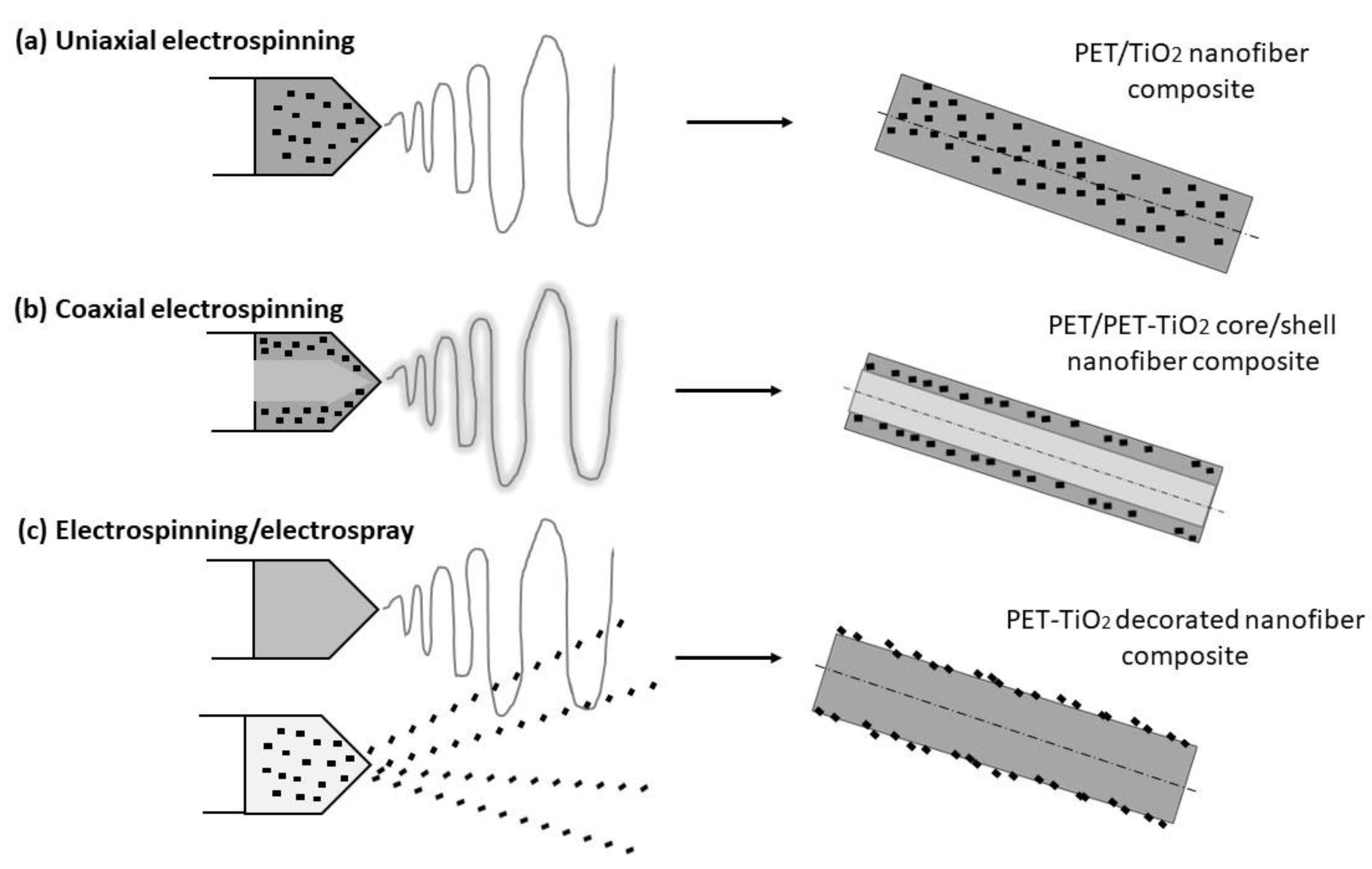
Figure 3.
SEM images of flexible nanofibrous photoanode mats: (a) PET/TiO2 nanofiber (UE); (b) PET/PET-TiO2 core/shell nanofiber (CE); (c-d) PET-TiO2 decorated nanofibers (E-ES); (e) Elemental composition of PET-TiO2 decorated nanofibers (E-ES).
Figure 3.
SEM images of flexible nanofibrous photoanode mats: (a) PET/TiO2 nanofiber (UE); (b) PET/PET-TiO2 core/shell nanofiber (CE); (c-d) PET-TiO2 decorated nanofibers (E-ES); (e) Elemental composition of PET-TiO2 decorated nanofibers (E-ES).
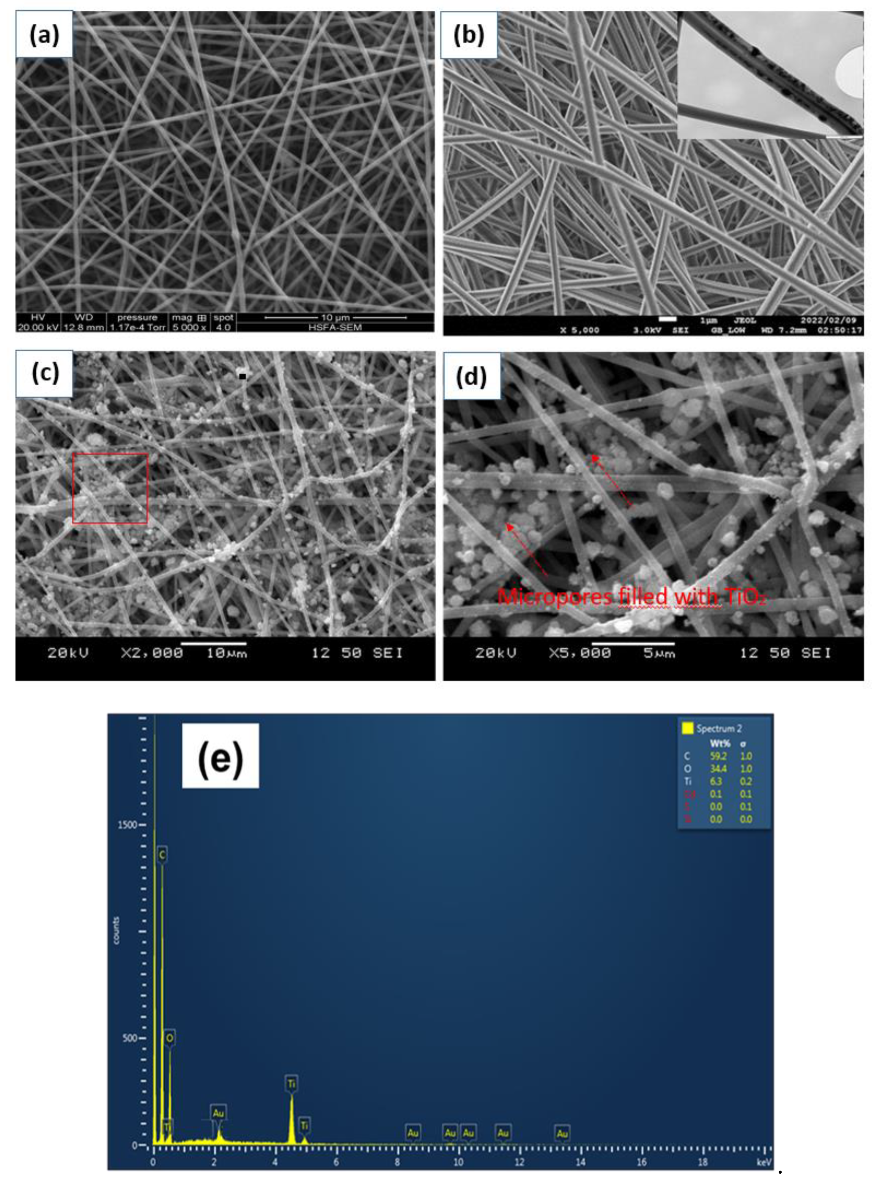
Figure 4.
(a) UV-visible adsorption curves of the desorbed dye from the nanofibrous mats produced through E-ES, CE and UE techniques, (b) the corresponding amount of dye loading.
Figure 4.
(a) UV-visible adsorption curves of the desorbed dye from the nanofibrous mats produced through E-ES, CE and UE techniques, (b) the corresponding amount of dye loading.
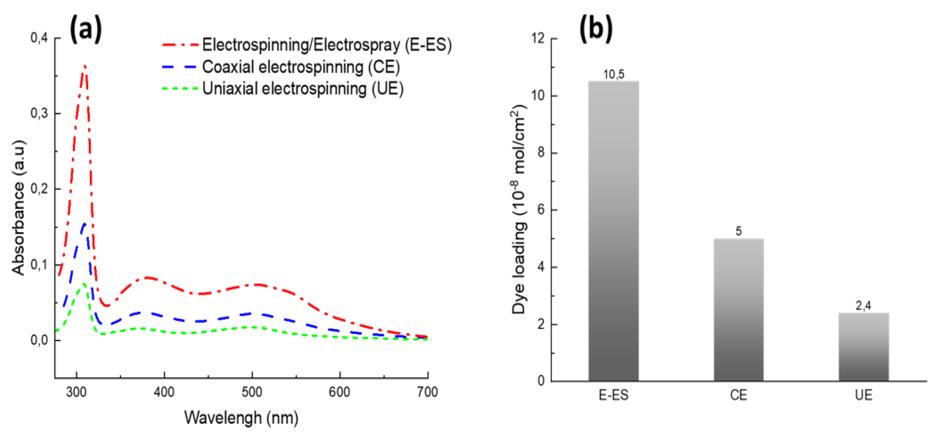
Figure 5.
(a) J-V curves of DSSCs prepared using flexible nanofibrous photoanode mats produced through E-ES, CE and UE methods; (b) Their corresponding photovoltaic parameters.
Figure 5.
(a) J-V curves of DSSCs prepared using flexible nanofibrous photoanode mats produced through E-ES, CE and UE methods; (b) Their corresponding photovoltaic parameters.
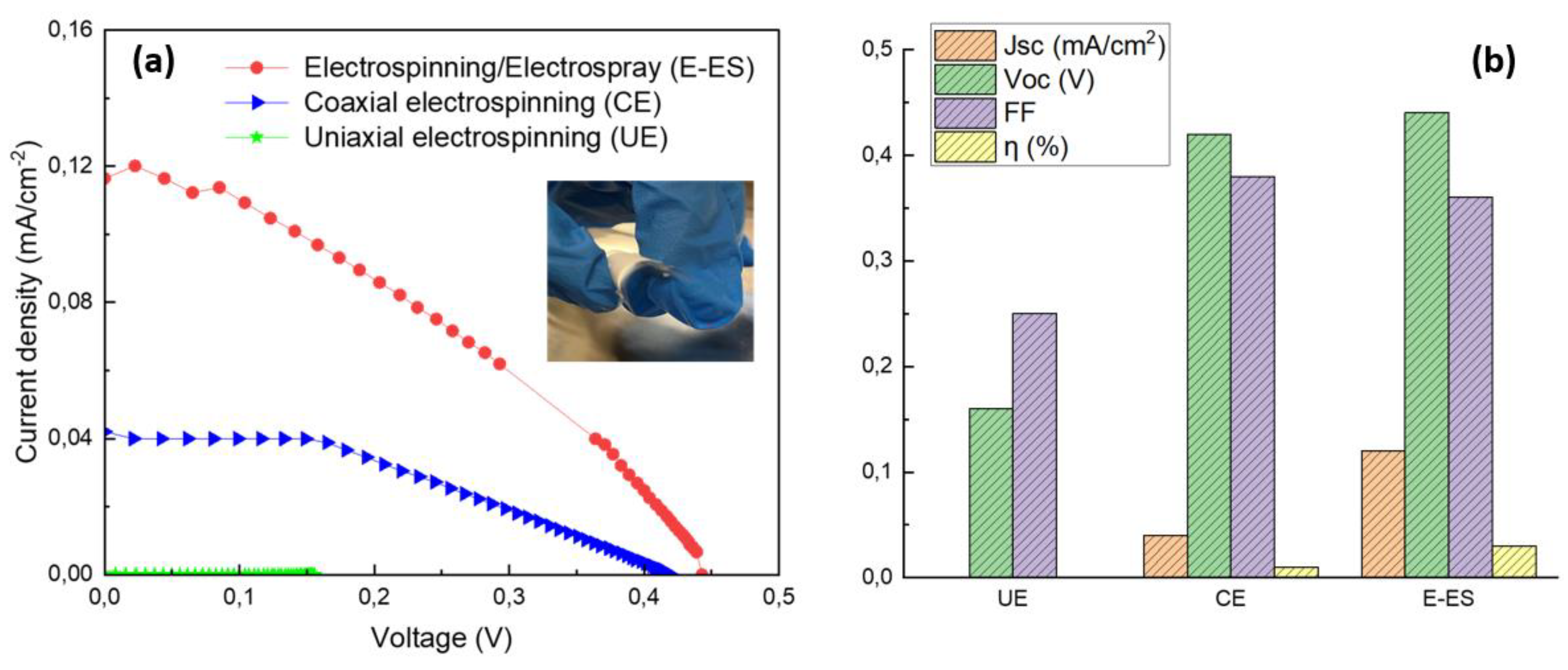
Figure 6.
(a) Nyquist plots of DSSC prototypes prepared using flexible photoanodes developed via CE and E-ES methods; (b) Equivalent electrical circuit used for fitting the EIS spectra of the cells. This process was completed using Zview software. R1 is series resistance, R2 represents the electron-transfer resistance at the electrolyte/Pt counter electrode interface, and R3 the electron transfer resistance at the photoanode/ N719 dye/electrolyte interface.
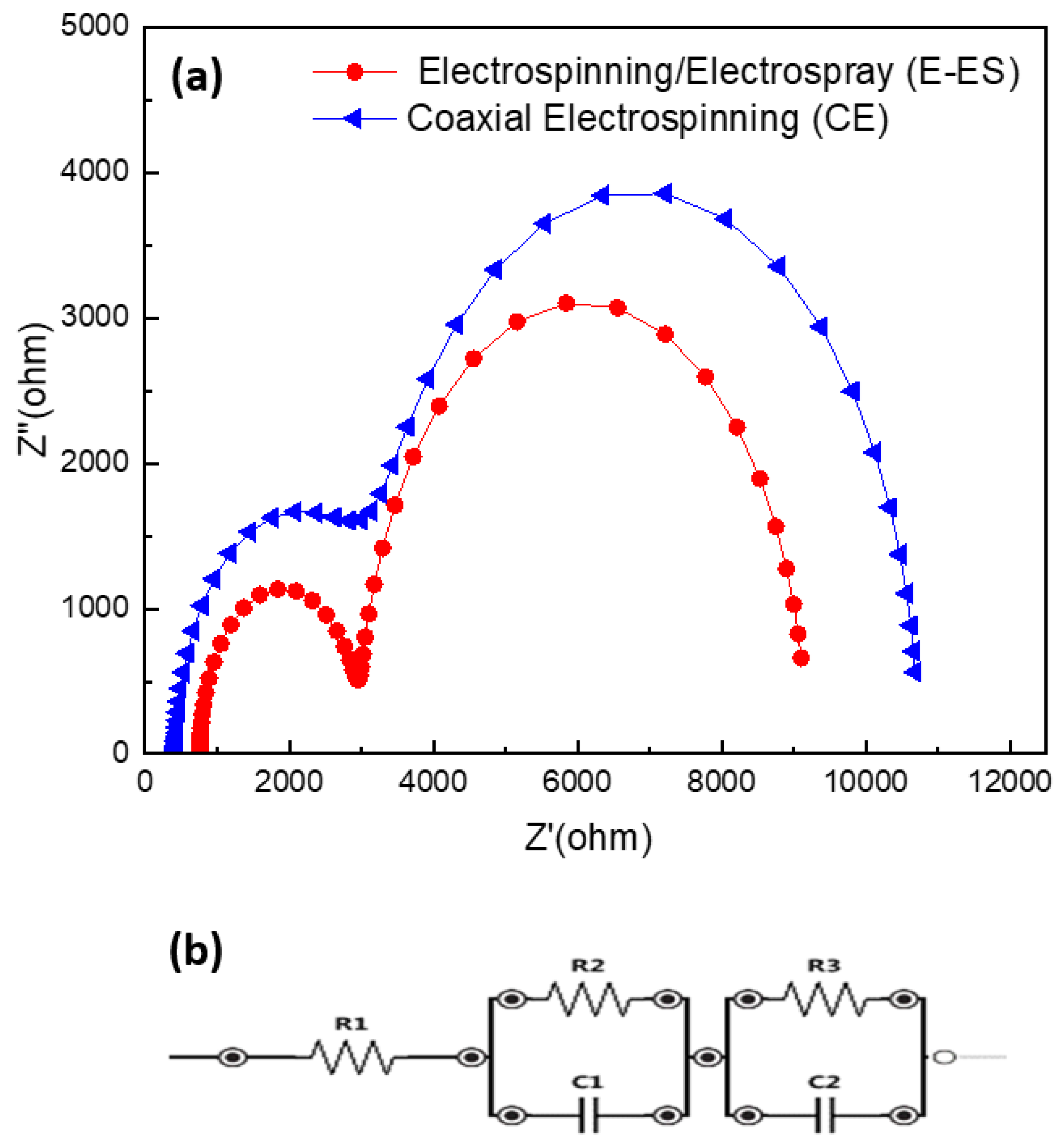

Table 1.
Operating parameters for each process used in this study.
| Process | Uniaxial electrospinning (UE) |
Coelectrospinning (CE) |
Electrospinning-Electrospraying (E-ES) |
|---|---|---|---|
| Flow rate (ml/h) | 1.0 | Shell: 0.6 Core: 0.7 |
E: 1.0 ES: 0.5 |
| Voltage (kV) | 22.0 | 23.4 | E: 23.4 ES: 18.0 |
| Tip-to-collectordistance (cm) | 15.0 | 14.0 | E: 14.0 ES: 10.0 |
Table 2.
Photovoltaic parameters of DSSC prototypes using flexible nanofibrous photoanode mats developed using different electrospinning methods.
Table 2.
Photovoltaic parameters of DSSC prototypes using flexible nanofibrous photoanode mats developed using different electrospinning methods.
| Electrospinning method used | Jsc (mA/cm2) | Voc (V) | FF(%) | η (%) | Rs(Ω) | Rct (Ω) |
|---|---|---|---|---|---|---|
| UE | 0.0003 | 0.16 | 0.25 | 1.8*10-3 | - | - |
| CE | 0.04 | 0.42 | 0.38 | 0.01 | 431 | 2741 |
| E-ES | 0.12 | 0.44 | 0.36 | 0.03 | 762 | 2214 |
Disclaimer/Publisher’s Note: The statements, opinions and data contained in all publications are solely those of the individual author(s) and contributor(s) and not of MDPI and/or the editor(s). MDPI and/or the editor(s) disclaim responsibility for any injury to people or property resulting from any ideas, methods, instructions or products referred to in the content. |
© 2024 by the authors. Licensee MDPI, Basel, Switzerland. This article is an open access article distributed under the terms and conditions of the Creative Commons Attribution (CC BY) license (http://creativecommons.org/licenses/by/4.0/).
Copyright: This open access article is published under a Creative Commons CC BY 4.0 license, which permit the free download, distribution, and reuse, provided that the author and preprint are cited in any reuse.


