Submitted:
16 May 2024
Posted:
17 May 2024
You are already at the latest version
Abstract
Design process can be divided into stages of analysis and synthesis. This paper presents the application of the object-oriented technique to the synthesis as well as theoretical considerations concerning to design of gear size ranges. The synthesis consists in composition (aggregation) of single details into units – according to the rule: “from details up to general view”. The basics of the object-oriented synthesis were formulated. Furthermore, the consecutive stages of synthesis were formulated. The interactions between these stages were discussed. Some aspects were described in details e.g.: creation of interfaces for performance of the embodiment phase the designed artefact via CAD system drawing with specification (dimensions are still parametrically set). The final step of the procedure is creation of so called substantial (concrete) form of artifacts i.e. final assignment of dimensions which stored in the special data base. The final stage of the design process is issuing of technical documentation (technical drawings) created automatically via CAD system. The considerations are terminated by the list of advantages connected with the object-oriented approach to design (in comparison to the traditional way).
Keywords:
Object oriented design
; gear size ranges
; phases of the object synthesis stage
; concretes
1. Introduction
In the Part I of this paper [1], the analysis of original methodology of shaping the constructional form of gear size ranges was presented. The basis of the methodology is creating models in the order of classes, subclasses and objects for a given super-class [2,3,4]. It is a typical object analysis in which the rule “from general to details view“ is used, which also appears in design theory [5,6,7,8,9,10]. Object analysis of a studied methodology is explained in details in the Part I of this paper [1] and concerns:
- theoretical basis,
- stages of object designing,
- partition of the problem making up the super-class into classes and objects,
- determining methods and attributes in classes,
- data-flow between classes and objects,
- models used in the design phases.
This paper, concerning object synthesis, is devoted to practical application of the methodology that is implementation. Implementation consists in design or actually shaping the forms of gears’ elements having characteristics of size range by ascribing particular values to them. As exemplary solution, a three-stage bevel-spur gear was presented.
The order of gears shaping (implementation) starting with elements e.g., geared wheels, shafts, bodies through sub-assemblies ending with assemblies is consistent with the most frequently used design rule “from general to details” (Figure 1). In this way, concretes in the form of automatic proposal of methodology appear.
At this stage, the designer interferes. Through feedback, there occur testing and correcting actions which improve the constructional form. The concretes [2] are documents which should be further processed leading to target drawings that is the record of design (engineering drawings).
2. Materials and Methods
2.1. Basic Assumptions
The examined issue was treated as in the case of object analysis as process attitude recommended by international standard of quality management ISO-9000:2001. The process, in this case object synthesis, is a set of interconnected and interactive activities which transform input into output.
Input is the result of the output analysis that is the ways of contact between the phases such as object data-bases with the parameters and object models, described in details in the previous article concerning object analysis. The process which transforms the above-mentioned results of output of analysis process is object synthesis which determines the following elements:
- phases of analysis that is: object design, constructing (detailed design), testing, initiation and maintenance,
- ways of contact between the phases in the form of data-bases and user menu.
The output of the process is documentation created in phases as a result of concretes of the designed construction and on their basis engineering drawings (Figure 2).
2.2. Phases of the Project of Object Synthesis Stage
As mentioned in Part I [1] concerning object analysis, the design process of object-oriented methodology consists of object analysis and object synthesis as implementation with assessment. This paper presents the following phases of synthesis, i.e., embodiment design, detailed design, testing, initiation and maintenance [5,6,8,10].
Object design as the process of analysis output and synthesis input is the conceptual stage, in other words it is the process of determining the components to create the construction. The ways of realisation of the task examined by determining functional structure are searched. The project does not include detailed construction properties, only the outline of geometrical constructional form. Afterwards, solution variants of the problem are created. One may use morphologic tables by means of which sets of alternative solutions of the designed problem are generated.
Constructional solutions include defined requirements as far as the performance of technical means is concerned and conception of their realization by determining of constructional form. Given constructional form and hierarchic structure of the examined problem one may separate components (elements) of solutions. The constructed elements receive the final constructional form needed for doing the project documentation.
It is necessary to mention here that going from the design process to constructing (detailed design) is often blurred. Therefore, the process is often called constructional design [9,10]. The main result of design are sets of detailed variants and the main constructing result are sets of constructions.
Object synthesis concerns design object constructing. It includes study by composing spaces of problem solutions and the mere constructing causing creation of concrete solutions. This process phase of the suggested design model is described in details in this paper concerning implementation of methodology in practice. However, the assessment whose aim is checking whether the solution meets all the requirements established when determining the needs and formulating the requirements, is realized in the last three stages i.e., testing, initiation and maintenance.
Testing consists in checking the technical characteristics. It is done in construction laboratory, in testing station and as validation at the customer’s. It is most often done by inspections, verification and the validation of the project and the product.
The inspection of the project is the widespread, systemised and documented examination of the project with the aim to assess its ability to meet the quality requirements and those resulting from the needs. It is also used to identify the existing problems and showing the suggestion of their solutions. It may be done on any stage of the design process. It is however optionally required after each design.
Verification is confirmation through examination and presenting objective evidence that the specified requirements were met.
Validation is confirming that the requirements concerning the specifically intended application were met. In designing and developmental works, validation applies to the process of examining the project and the product in order to affirm its conformity with the user’s needs established earlier. The usefulness of the suggested solutions is also often assessed by means of weighted criteria method and predicted characteristics of the product are compared with the aims and criteria established earlier.
Initiation is the constructor’s supervision over the prototype construction. In the case of gears these are the bodies, toothed elements, shafts and other parts’ models. After that, the possibilities of correct assembly is checked. As experience at initiation of projects showed, dissatisfaction with their realization most often was the result of badly specified requirements, unidentified design errors, the lack of clear-cut establishing of functional requirements and the lack of use of correcting and preventing actions.
Maintenance of the project is its constant improvement. This requirement is necessary so that the designed product showed the highest level of quality and safety consistent with European Union directives. The quality tools most frequently used here are the analysis of causes and results of faults occurrence.
The problems the designer deals with during the design process of the gear size range may be routine or non-routine. The routine problems are solved by means of algorithms and procedures [2]. Non-routine problems characterized by novelties are divided into innovative and creative. However, redesigning problems include the issues already existing but through modification meet additional requirements. They concern adaptation and variant tasks. When testing ordered sets i.e., the gear size ranges, as in the following paper, it is best to use variant and parameterization techniques [6].
Variant structure of construction family results from the variety of constructional solutions, variations or modification of the same project. Constructional variants are the sets of constructional solutions which are the variations of their basic solution. The amount of variants depends on the range of quality variation of characteristic features and constructors’ creativity.
In parameter designing the structure of the object designed is known [5,6,11]. When designing one should determine the values of design variables. The rule of such designing is the fact that the existing tested project, which in the case of size ranges is the base quantity, is the basis to create similar most often geometrically similar derivative projects having different performance [12,13,14,15,16].
Such attitude is determined by:
- the rules of creating unified values of properties,
- presenting constructional solutions after determining the values of their dimensions by means of algorithms,
- optimisation of variety of constructional properties with the use of automatic classification with final generating of constructional documentation.
2.3. Ways of Contact between the Phases
2.3.1. Components of Object-Oriented Design
In the model of object-oriented design four components were used:
- the domain of the problem determines objects realizing the basic functions of the issue examined e.g., as for gears these are geared wheels, shafts, bodies and sub-assemblies,
- management of tasks distinguishing elements of the system which enable realization of the task e.g., methods being algorithms,
- data management,
- contact with man.
2.3.2. Data Bases
One of the tasks of object-oriented methodology is ordering and enabling creation and access to the data [14,15,17]. The process constitutes the essential component part of the whole system of storing and processing information described as engineer data bases (Figure 3). The structure of computer aided design CAD integrated with Computer Aided Engineering, Product Data Management, data bases and other software aiding methodology was shown in Figure 3. The model used in the studied methodology is the most frequently used model of relational data bases.
2.3.3. User Menu
The component of contact with man is used to determine the ways of creating interfaces used for realization of the project on the way system-user. Appropriate user menu in the suggested methodology was shown below (Figure 4) using the example of three-stage bevel-spur gear train.
The structure shows the main menu with the hierarchy of going deeper into the menu of lower level during the designing process, including creating constructional form of the assemblies, sub-assemblies and elements of three-stage bevel-spur gears’ size ranges.
By means of management of menu functions one may create one’s own communication with the user. Leading the user in this system is realized by graphic menu. Tabular menu displayed on the alphanumeric monitor may be used for different aims. In the menu of commands choice, individual row are interpreted as commands which will be directly generated and done. In order to assign the values to the system variables or user’s variables, tabular variables menu is used.
One may then gather frequently used variables in one table and assign to them appropriate values without the need to display various tabular menus. Tabular menu of drawings being the basis of communication with the constructor uses the properties of menu of commands choice and hierarchic menu. Opening the next window (in tabular menu) is done after choosing appropriate line from the current window. The hierarchy of tabular structure is done by reference to other windows and path choice.
2.4. Documentation Created in Phases
On individual stages of object design, documents or drawings in both electronic and paper form are made which are appropriately supervised and stored. In the methodology, the following kinds of documents were used:
- object modelling which is the set of classes and objects is stored as a program on logical disks and in the printed form of classes and objects list,
- input data to the object-oriented designing created as a result of engineering calculations are gathered in data-bases,
- diagrams of hierarchical, entity-relationship, data-flow and object models are created in a graphic way on the screens and then printed on the paper as the engineering drawings to the analysis,
- results of concretes in the form of drawings for further processing are gathered electronically in files,
- engineering drawings of the construction which are detail or assembly target drawings are stored electrically by Product Data Management system or printed on tracing paper to be stored in archives.
The two latter kinds of documents are the results of synthesis and are presented in more details in this paper, however, the others are the result of analysis and at the same time the input to the synthesis.
PDM system gathers data about the product, stores documentation and manages the project. It is the connector of two environments of information storing: data-base and document environment. Apart from improving the access to information, the system assures effective protection of data against their uncontrolled leak. Each document and information has their own access status which automatically protects them against undesirable readout.
Its biggest advantages are:
- creating common, homogenous and generally accessible information bank,
- possibility to keep necessary restrictions in access to data-base,
- organizing the stored information into free structures determined by the user,
- avoiding redundancy of stored data, which results in their absolute validity,
- organised storing of a lot of versions of the same information packet with annotations concerning changes,
- appropriate mechanism of informing management according to specific criteria.
Summing up the issue of creating and supervising of the documentation generated in design phases and all stages connected with product manufacturing one may claim that a very important element of the process is storing, especially electronic storing. For the administrators, it is the perspective of the fastest developing computer technology nowadays and possibilities of free adaptation of software to the changing conditions of a company functioning. For the management and supervising units, electronic supervision over documentation means direct access to the information in the company independently of the storing place and therefore possibility of generating all kinds of technical documentation, overview list, diagrams, reports, etc.
3. Creating Concretes
The process of shaping of constructional form starts with reshaping the objects created in the process of object analysis into element concretes by giving the objects the real value [2,15]. The input data are here geometrical parameters of the gear such as axes distance, toothed elements’ diameters, shafts dimensions, angles of tooth inclination, basic dimensions of bodies and normalized elements numbers, e.g., rolling bearing.
The example are spur and bevel geared wheels, slow-speed, intermediate, high-speed toothed shafts as global elements. The concretes of body housings, input sleeves of angular attachment are created in a different way as local. They are ascribed to appropriate attributes i.e., the number of gear stages e.g., three-stage, location – with coiled axes and the shape of housing as horizontal view of the rectangular housing.
Base objects are here types of gear size ranges e.g., 2-, 3-, 4-stage, bevel-spur. Derivative objects of housings for different stages and locations of the gear axis are created out of those objects. These are less universal objects in the form of views and sections of bodies and input sleeves. They limit the range of designer’s abstraction when shaping the housing and at the same time they influence the features of a specific similarity and assure unification of the gear created.
In a similar way the concretes of sub-assemblies and assemblies are made, on the basis of corresponding elements. The result of the above-mentioned elements’ composition are assemblies of gear models e.g., bevel-spur gears (Figure 5).
The models as mentioned before are connected with the number of transmission stages, the location of the axis and the shape of housing. Each gear assembly consists of the housing and sub-assemblies. Sub-assemblies consist of shafts and geared wheels as well as trade and normalized parts, bearings, rings, keys, etc.
4. Formation of Engineering Drawings
The concretes formed are the documents which must still undergo processing leading to target drawings i.e., engineering’s drawings [18,19,20]. In this phase of design, each detail or assembly drawing is identified by its individual name which in storing programs is its address (Figure 6):
-
geared wheels, slow-speed shaft and pinions – their name consists of three parts (e.g., K02-112-4,0, …):
- the first one – letter K – cylindrical elements, KS – bevel elements, then the number of axis (e.g., 0, 1, 2, 3, 4) and the element type – slow-speed shaft without the number, pinion – 1, geared wheel – 2,
- the second one – distance of axes for spur/cylindrical elements, value (diameter of bevel gear on intermediate shaft) for bevel elements (e.g., 71, 90, 112),
- the third one – partial transmission (e.g., 2.5, 4),
-
bodies – the name consist of four parts (e.g., 3R – RP – 112 – 25):
- the first one – the number of gear stages in the form of numbers (e.g., 2, 3, 4) and the letter R for spur gears and RK – for bevel-spur gears (e.g., 2R, 3R, 4R, 2RK),
- the second one – the type of axis, R – uncoiled, Z – coiled and the housing shape, P – rectangular, O – round,
- the third one – the distance of axes on the last stage (e.g., 112),
- the forth one – total transmission of the gear (e.g., 25),
-
angular attachments – name – (e.g., PK -71-2.5) – consists of three parts:
- the first one – letters PK,
- the second one – the size of the attachment (e.g., 71, 90, 100, 118),
- the third one – partial transmission (e.g., 2.5, 4)
-
sub-assemblies on particular stages of the gear – their name (e.g., K11K12-90) consists of two parts:
- the first one – consists of initial parts of the slow-speed shaft or pinion name and geared wheel located on it (K0K02, K11K12),
- the second one – distance of axes (e.g., 71, 90, 112),
- assembly drawings – the name consists of five parts (e.g., Z-3R-RP-112-25):
- the four one – are inherited from identification of the body included in the assembly,
- the fifth one - precedes all parts with the letter – Z.
The engineering drawing are formed in a similar way as concretes according to the rule “from general to details” i.e., starting with the drawings of elements through sub-assemblies to assemblies.
The detail drawings of the studied gear elements are concretes completed with additional views, sections, geometrical dimensions and tolerances placed on the drawings or the tables, technological parameters presented in the drawing annotations, measurement values, annotations concerning mechanical and heat working and roughness class, and other recommendations. In this way detail drawings of gear elements i.e., pinions, shafts, sub-assemblies and bodies are created (Figure 7).
In a similar way other sets of the designed gears are created according to suggested methodology i.e., detail and assembly drawings of bevel segment (Figure 8) and the whole three-stage bevel-spur gear train.
5. Discussion - The Assessment of Methodology of Object-Oriented Design of Gear Size Ranges
In this article we have compared the labour consumption of the design of the studied gear size range according to the suggested methodology, both analysis and synthesis, of object-oriented design of gear size ranges with the labour consumption of designing of a similar size range using the method applied until this methodology is implemented, called the conventional method. Conventional design was computer aided design in which engineering calculations and engineering drawings were done separately for each gear forming the designed size range. In this method the CAD system used for drew the construction was used only as a graphic editor.
In the suggested methodology, shaping of constructional form of gear size range consists in drawings merely the construction of a representative of the size range i.e., so called base gear. The writing of other transmissions’ constructions which are the derivatives of the basic one is done automatically. As mentioned before, in the final stage of design, only a small completion of constructional documentation is necessary which must be done separately for each gear. Thanks to comparing the times according to those methods it will be possible to determine the main results obtained thanks to the use of methodology of object-oriented design of gear size ranges [21,22].
Comparison of the designing times divided for separate stages for an individual three-stage bevel-spur train (basic) and the whole size range consisting of n gears (basic + (n-1) derivatives) was shown in Table 1.
The stage of writing the gear size range construction according to the suggested methodology consists of:
- object analysis, i.e., forming classes, sub-classes and objects, determining attributes and methods in individual classes, creating data-flow diagram between classes and sub-classes, creating models in phases and data-bases,
- object synthesis is creating concretes and element drawings, sub-assemblies and assemblies only for the basic gear using the user menu,
- generating design documentation for all gear of the size range,
- completing constructional documentation.
Object analysis is almost entirely performed on the example of basic gear. The time needed for doing it, for size ranges of the studied gears, is 16 hours and additionally (n-1) hours for generalization of analysis for all derivative gears.
Object synthesis done entirely on the example of the basic gear takes, thanks to the use of objectivity advantages, smaller number of hours in comparison to conventional write of the construction i.e., 40 hours.
Generating design documentation for all gears of size range is entirely computer aided thanks to the use of graphic system CAD properties and the prepared methodology [15,16,18]. Therefore, the time needed for generating documentation depends only on the quality of user menu allowing less or more efficient introduction of appropriate commands and in average conditions may be maximum 0.5 hour (auxiliary time added) independently of the number of gears forming the size range.
The last sub-stage of shaping constructional form of all gears of the size range consisting in completing the design documentation take about 6 n hours.
The time needed to check and confirm the documentation formed according to the suggested methodology is far shorter and amounts to 8 + 4 (n-1) hours.
Comparing the times needed for making constructional documentation according to both methods, one may conclude that the efficiency of the suggested methodology increases with the increase in the number of gears forming the size range. Therefore, in the case of n = 5 the labour consumption decreases by over 60%, and when n = 7 by about 70%.
Thanks to implementation of the methodology expect for shortening the time and therefore reducing the costs of making engineering documentation, surd/irrational/incommensurate application effects such as:
- single-time performing of object syntheses for the entire size range when in the case of conventional method, the engineering drawing of each value must be done individually,
- using existing concretes (elements or sub-assemblies) in the construction of gear size ranges having other number of stages or gear size ranges of other kinds,
- facilitating the control of design process stages by introducing one diagram for all size range values,
- facility in making frequent corrections without the need to replace the whole documentation,
- object design influences the properties of specified similarity and assures unification which is very significant when creating gear drives,
- preparing objects for modular-segment design based on selection using advisory systems and artificial intelligence were obtained,
- facilitates the so-called responsible design, including introducing sustainable innovations [23].
Author Contributions
Conceptualization, W.C. and J.R.; methodology, W.C. and J.D.; software, W.C.; validation, Y.O., K.A. and A.Z.; formal analysis, A.Z. and Y.O.; investigation, K.A. and Y.O.; resources, A.Z.; K.A., Y.O.; writing—original draft preparation, W.C., J.R., and J.D.; writing—review and editing, J.D.; A.Z., and Y.O.; visualization, W.C., and J.R.; supervision, A.Z.; K.A. and Y.O.; project administration, A.Z. and K.A.; funding acquisition, A.Z. and Y.O. All authors have read and agreed to the published version of the manuscript.
Funding
This work has been supported financially by the research project (АР19677356 - To develop systems for controlling the orientation of nanosatellites with flywheels as executive bodies based on linearization methods) of the Ministry of Science and Higher Education of the Republic of Kazakhstan and was performed at the Research Institute of Communications and Aerospace Engineering in Almaty University of Power Engineering and Telecommunications named after Gumarbek Daukeyev, which is gratefully acknowledged by the authors.
Data Availability Statement
Data are contained within the article.
Acknowledgments
This work received financial support from the Almaty University of Power Engineering and Telecommunications, named after G. Daukeyev, and was performed at the Institute of Communications and Aerospace Engineering, which is gratefully acknowledged by the authors.
Conflicts of Interest
The authors confirm that they have no conflict of interest with respect to the work described in this manuscript.
References
- Czader, W.; Drewniak, J.; Zhauyt, A.; Rysiński, J.; Alipbayev, K.; Aden, A. Process of object-oriented design of gear size ranges. Part I: analysis. Processes 2024. [CrossRef]
- Rumbaugh, J. Object-Oriented Modelling and Design. Prentice Hall Int., Englewood Cliffs, New York 1991.
- Yourdon, E. Object Analysis and Design – Examples of Applications. Yourdon Press, 1999.
- Coad, P.; Yourdon, E. Object-oriented design. Yourdon Press, 1991.
- Eggert, R.J. Engineering Design. Pearson Prentice Hall NewJersey, 2005.
- Pahl, G.; Beitz, W. Engineering Design. Springer-Verlag London Limited 1996.
- Drewniak, J. (ed.). Computer Aided Design of Gear Size Ranges. University of Bielsko-Biała 2000 (in Polish).
- Chakrabarti, A.; T. M. Blessing, L.T.M. (eds.). An Anthology of Theories and Models of Design. Springer-Verlag London 2014.
- Pieter E. Vermaas, P.E., Vial, S. Advancements in the Philosophy of Design. Springer International Publishing AG 2018. [CrossRef]
- Hubka V.; Eder E.W. Engineering Design: General procedural model of engineering design. Edition Heurista, Zurich 1992.
- Simpson, D.J.A.; Murray, J.L.; Simmons, J.E.L. The object-oriented paradigm applied to the design and analysis of gearboxes, J. Engineering. Design 1997, 8, 2, pp. 175-189, 1997. [CrossRef]
- Wu, J.C.; Poppa, K.; Leu, M.C.; Liu, X.F. Integrated function structure and object-oriented design framework. Computers in Industry 2005, Volume 56, 699-718. [CrossRef]
- Li, J.R.; Khoo, L.P.; Tor S.B. An object-oriented intelligent disassembly sequence planner for maintenance. Computers in Industry 2012, Volume 63, 458-470. [CrossRef]
- Jiang, S.; Jing, L.; Sun, T.; Xu, Q.; Peng, X.; Li. J. A conceptual scheme improvement approach based on the performance value of the principle solution taking a coal mining machine as a case study. Computers in Industry 2019, Volume 105, 17-34. [CrossRef]
- Kohlhase, N.; Birkhofer, H. Development of modular structures: The prerequisite for successful modular products, J. Engineering Design 1996, 7, 3, pp. 279-291. [CrossRef]
- Latif, M.N.; Mannam, R.G. Feature based design and the object-oriented approach, J. Engineering Design 1996, 7, 1, pp. 27-37. [CrossRef]
- Tomohiko Sakao, T.; Shimomura, Y.; Sundin, E.; Mica Comstock, M. Modeling design objects in CAD system for Service/Product. Engineering Computer-Aided Design 2009, 41, 197–213. [CrossRef]
- Mak, K.L.; Wong, S.T.W.; Lau, H.Y.K. An object-oriented rule-based framework for the specification of flexible manufacturing systems Computers in Industry 1999, 39, 127–146. [CrossRef]
- Schachinger, P.; Johannesson, L. Computer modelling of design specification. J. Engineering. Design 2000, 11, 4, pp. 317-329. [CrossRef]
- Rajbabu, K.; Sudh, S. A novel rule-centric object oriented approach for document generation. Computers in Industry 2014, 65, 235–246. [CrossRef]
- Leibl, P.; Hundal, M.; Hoene, G. Cost calculation with a feature-based CAD system using modules for calculations, comparison and forecast. J. Engineering Design 1999, 10, 1, pp. 93-102. [CrossRef]
- Barton, J.A.; Love, D.M.; Taylor, G.D. Design determines 70% of cost? A review of implications for design evaluation. J. Engineering Design 2001, 12, 1, pp. 47-58. [CrossRef]
- Hernandez, R.J.; Goñi, J. Responsible Design for Sustainable Innovation: Towards an Extended Design Process. Processes 2020, 8, 1574. [CrossRef]
Figure 1.
Object synthesis (implementation) according to the rule “from general to details”.
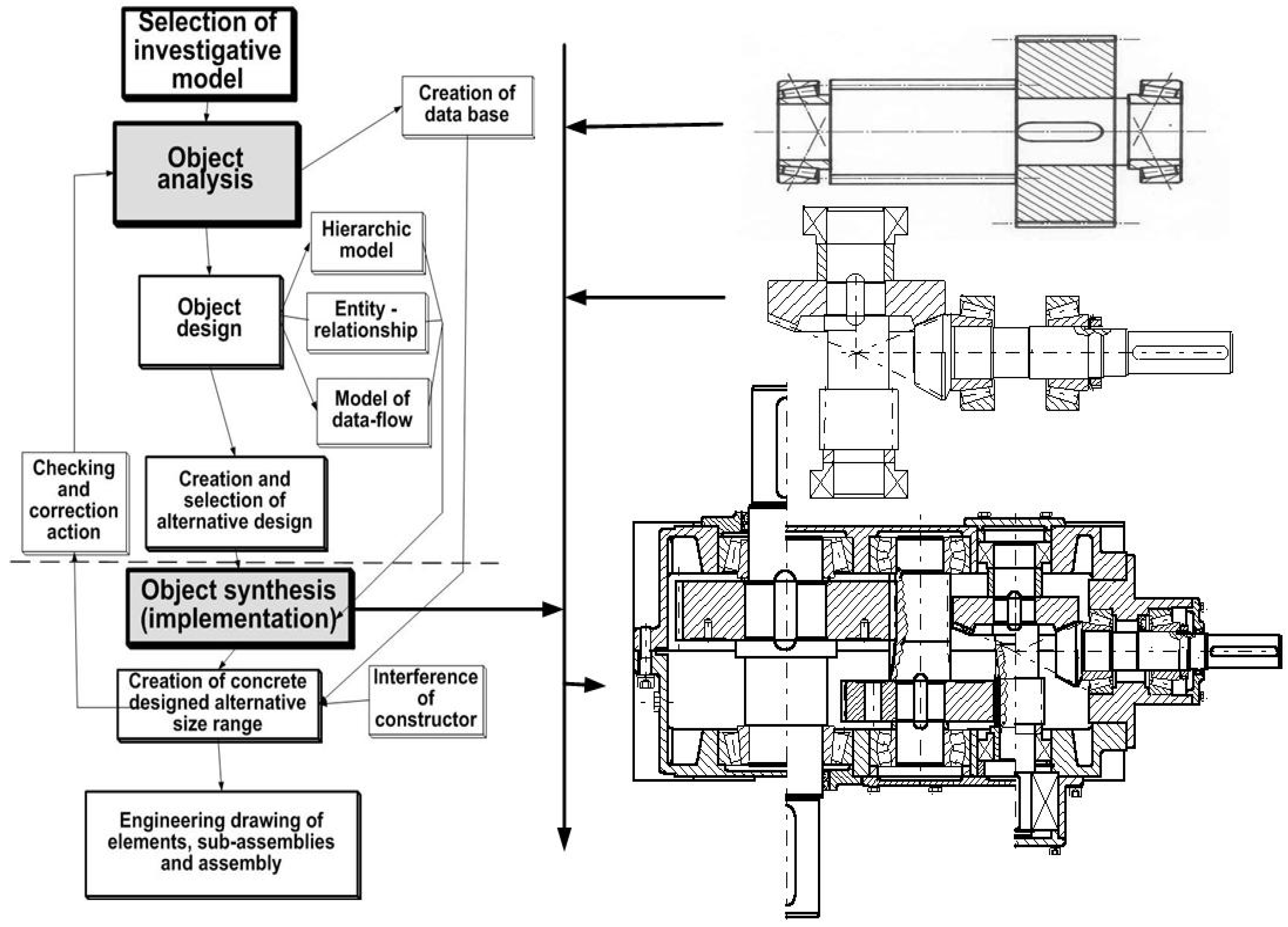
Figure 2.
The elements of the object-oriented design synthesis.
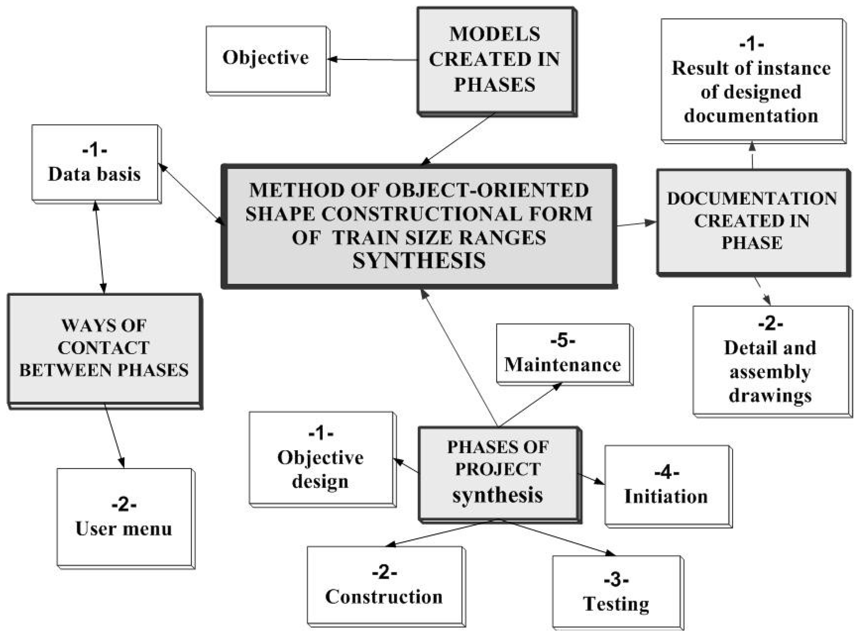
Figure 3.
The structure of environment of computer aided of design process.
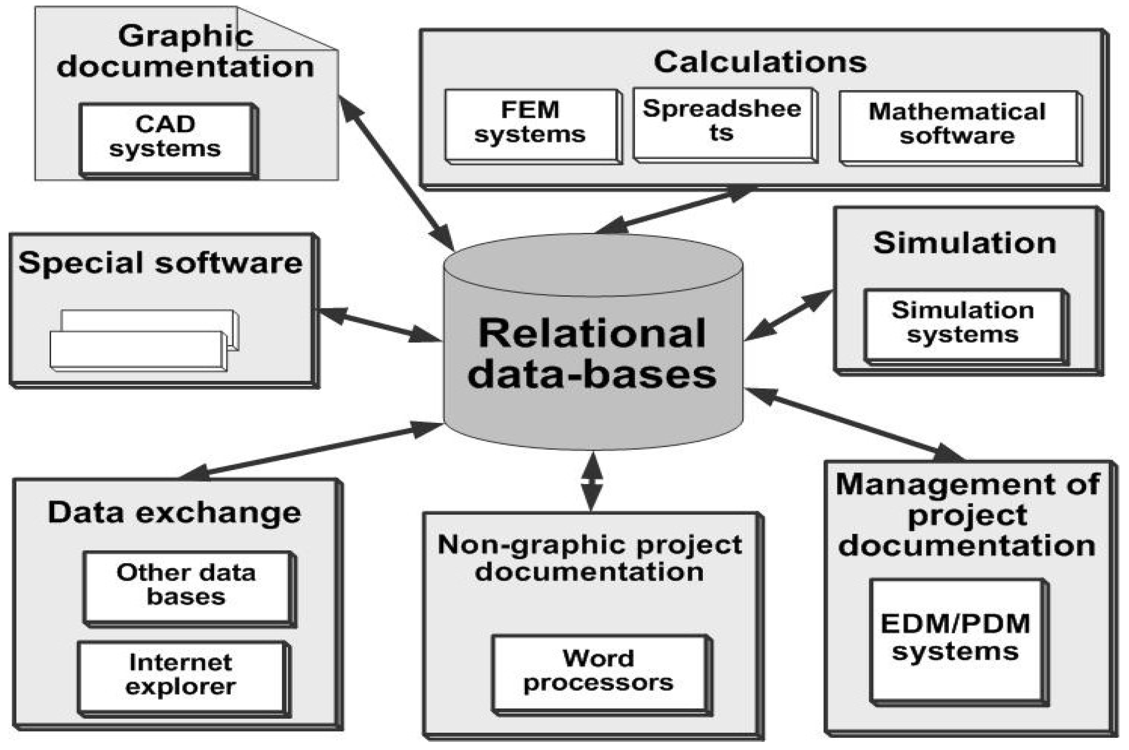
Figure 4.
Diagram of the structure of contact between the system and the user.
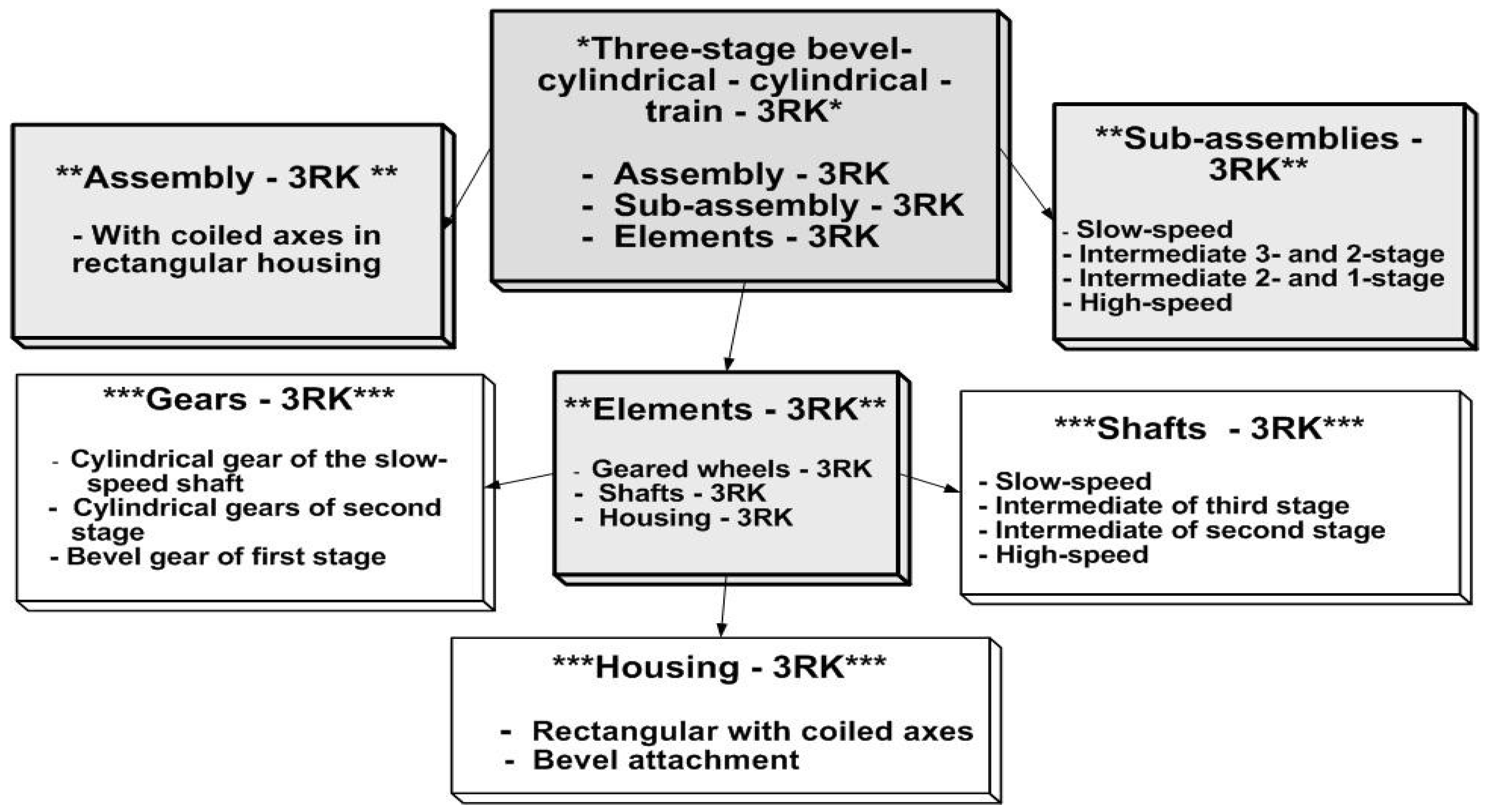
Figure 5.
Drawing of concretes of three-stage bevel-spur gear train.
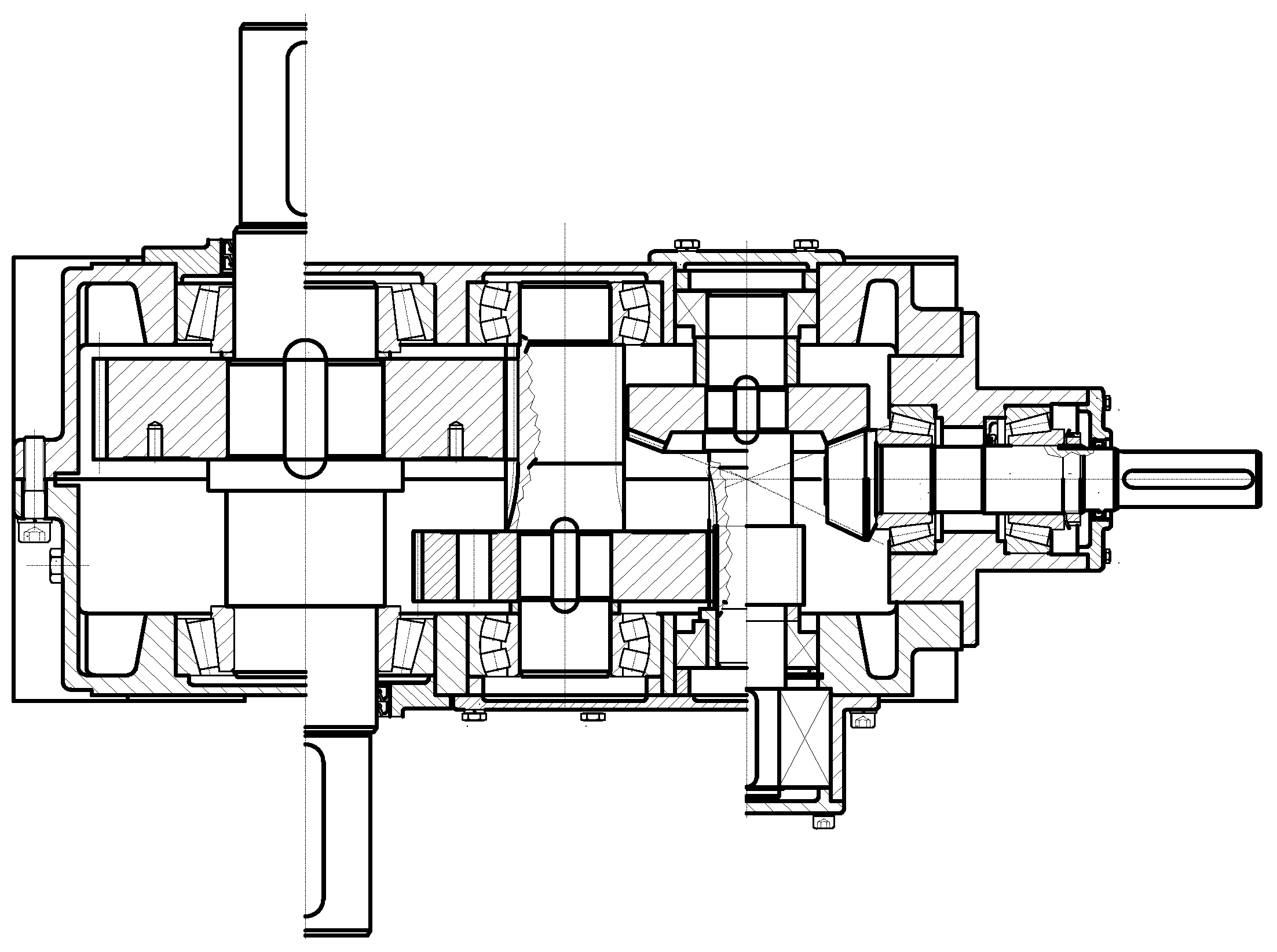
Figure 6.
Diagram of drawings identification of three-stage bevel-spur gear trains.
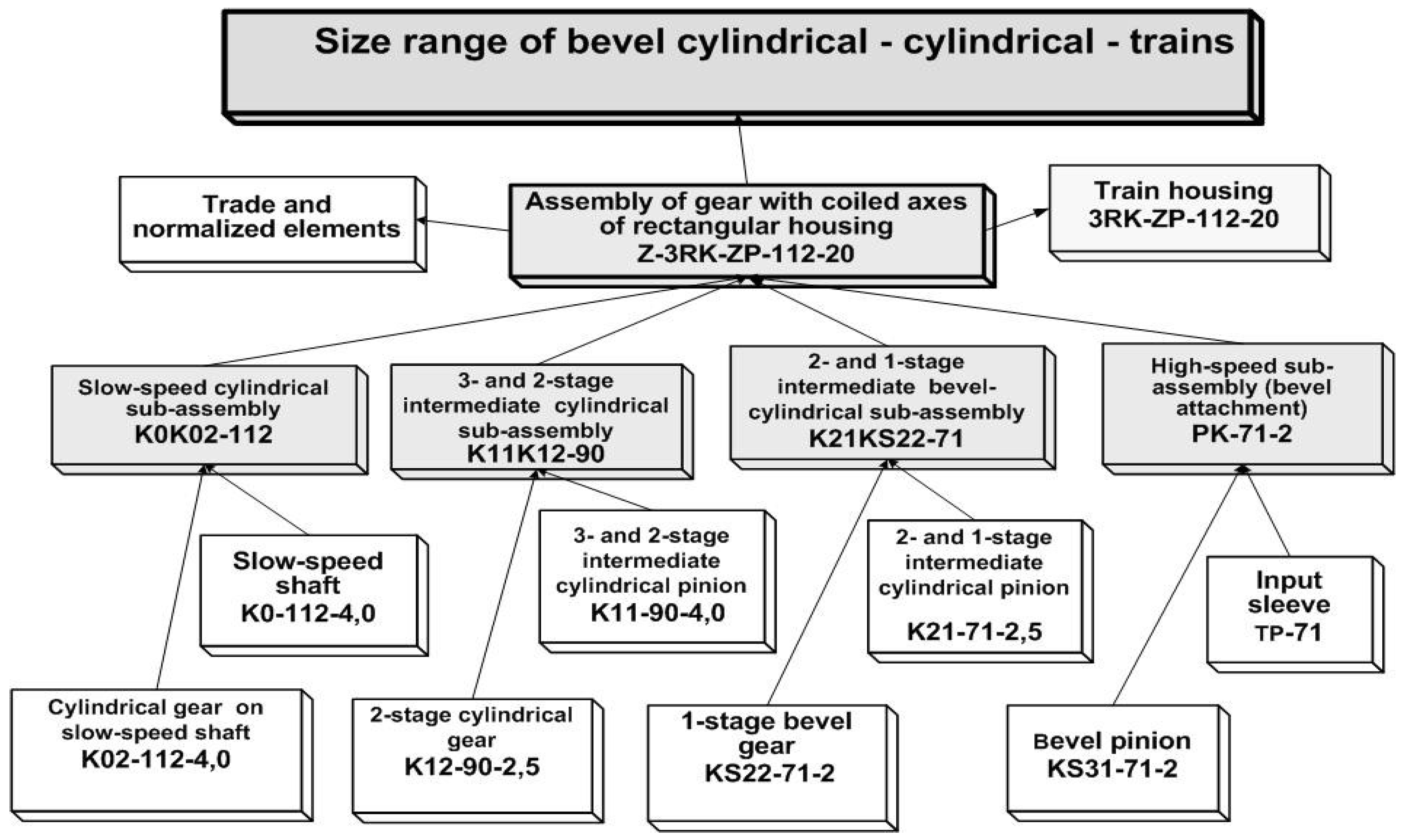
Figure 7.
Detailed drawings of elements of spur segment of the studied gear train.

Figure 8.
Detailed drawings of bevel segment elements of three-stage bevel-spur train.
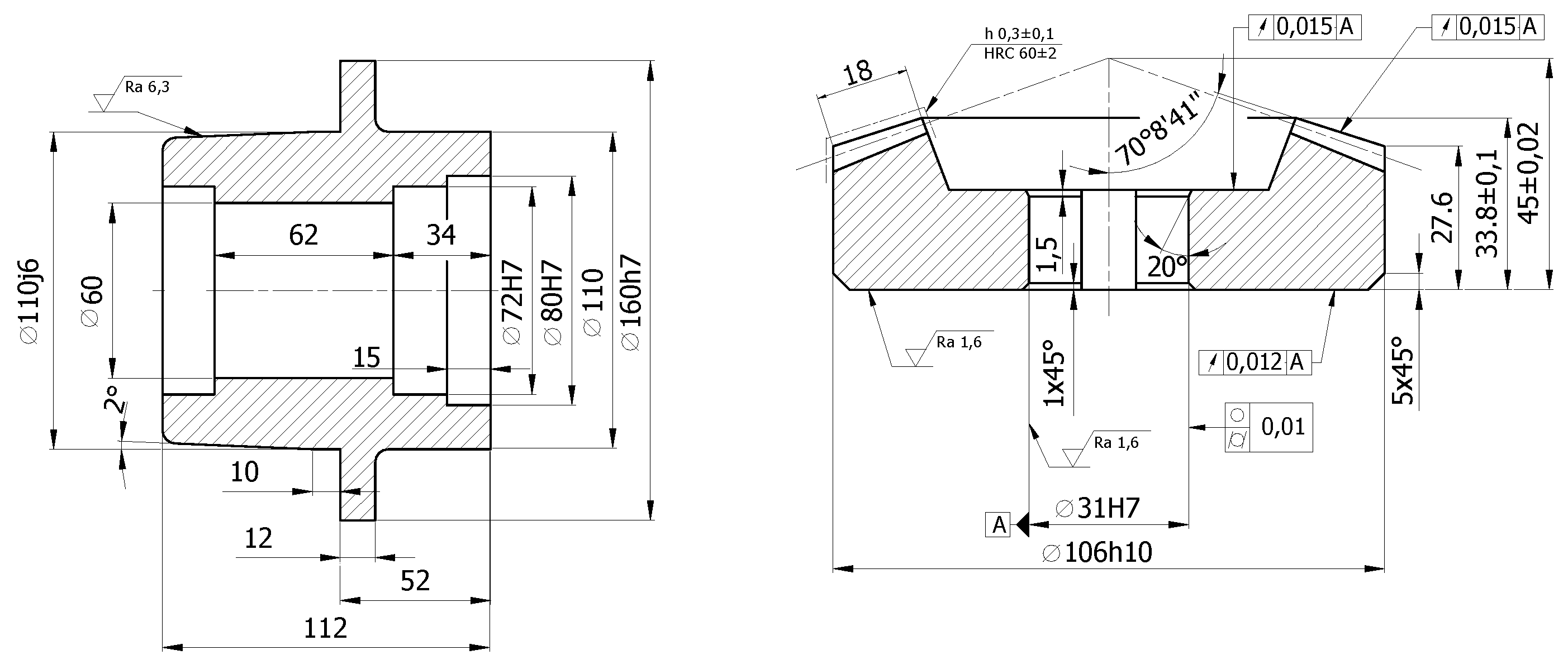
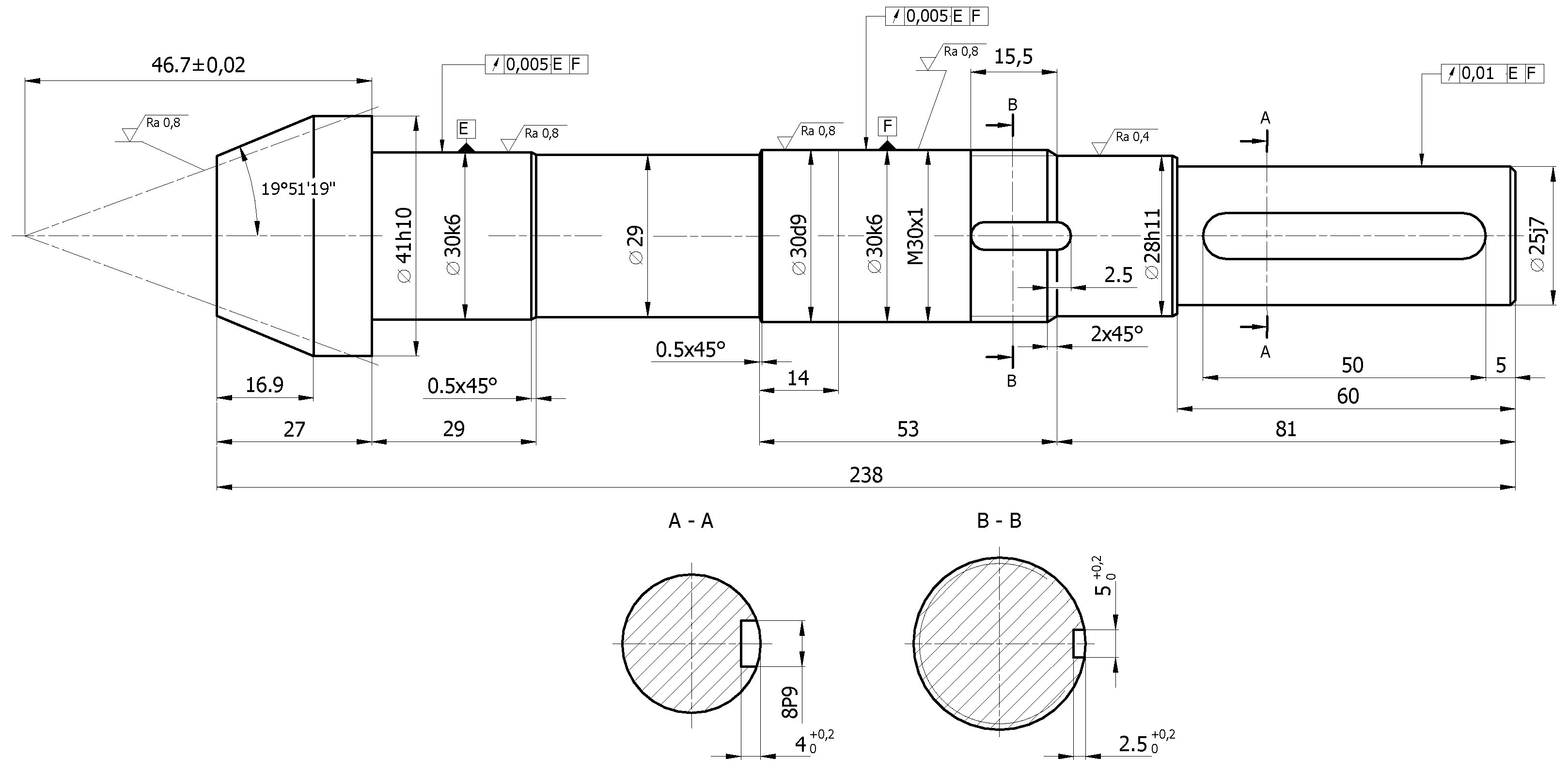

Table 1.
Comparing approximate times of size range (made up of n-stage bevel-spur trains) design.
| Design stages | Design time (in hours) | |||
| According to conventional method | According to suggested metod | |||
| One gear | Size range | One gear | Size range | |
| Conceptual design | 8 | 8+2(n-1) | 8 | 8+2(n-1) |
| Calculations | 16 | 16n | 16 | 16n |
| Embodiment and detail design | 48 | 48n | 62 | 62+7(n-1) |
| Documentation checking | 16 | 16n | 8 | 8+4(n-1) |
| Documentation plotting | 3 | 3n | 3 | 3n |
Disclaimer/Publisher’s Note: The statements, opinions and data contained in all publications are solely those of the individual author(s) and contributor(s) and not of MDPI and/or the editor(s). MDPI and/or the editor(s) disclaim responsibility for any injury to people or property resulting from any ideas, methods, instructions or products referred to in the content. |
© 2024 by the authors. Licensee MDPI, Basel, Switzerland. This article is an open access article distributed under the terms and conditions of the Creative Commons Attribution (CC BY) license (http://creativecommons.org/licenses/by/4.0/).
Copyright: This open access article is published under a Creative Commons CC BY 4.0 license, which permit the free download, distribution, and reuse, provided that the author and preprint are cited in any reuse.


