Submitted:
01 May 2024
Posted:
01 May 2024
You are already at the latest version
Abstract
The interest in flying wings dates as far the early years of the aviation age. Over the 20th century, numerous attempts were made to investigate the feasibility of the concept, which demonstrated numerous early benefits: increased aerodynamic efficiency, reduced fuel consumption and lower noise and pollutant emissions compared to conventional tube and wing aircraft.
However, major technical challenges prevented that type of design from entering mass production, especially with regards to structural design and manufacturing, stability and control and ride quality. In the 1990’s, a new concept, the blended wing body (BWB), was created to alleviate some of the concerns of flying wings while maintaining increased efficiency. Despite the promise, technical hurdles once again proved to be a deal breaker, and as of 2024, the only flying wing to enter serial production is the B-2 Spirit, an extremely complex and expensive aircraft.
Thirty years later, as the world is quickly transitioning towards cleaner energy, the interest in the blended wing body has been renewed. The latest technological advancements in the aerospace industry should make the development of the BWB more plausible, however passenger comfort issues remain.
Surprisingly, the BWB development may come from an unexpected application: as a tanker aircraft. As the U.S. Air Force is seeking a replacement to hundreds of aging tankers, a startup company was recently funded to develop the concept and build a prototype.
In this study, we explore the history of blended designs from its early days, highlighting its opportunities and challenges – and why the design is an intriguing fit for application as a tanker aircraft.
Keywords:
USAF
; NGAS
; tanker
; BWB
1. Introduction
1.1. Brief History of Flying Wing Designs
It is appropriate to state that, in the early days of aviation, configurations resembled neither the dominant tube and wing nor flying wing configurations, with most aircraft featuring a wooden structure and fabric wings. The first aircraft with a design feature resembling a flying wing was the Dunne D-8 (1911), a tailless biplane featuring swept wings and washout to prevent tip stall and increase pitch stability [1]. In the 1920’s, a series of tailless aircraft, known as Westland-Hill pterodactyl, demonstrated looping and rolling capabilities [2].
The term flying wing is adequate to describe tailless aircraft that have no distinct fuselage, carrying its crew, payload and fuel inside the wing structure. The semi flying wing, developed by Jack Northrop in 1928, has no fuselage but still features vertical stabilizers [3]. Intrigued by the aerodynamic benefits of fewer non lifting surfaces, Northrop’s developments led to a pure flying wing in 1940, the N-1M “Jeep”. The design, shown in Figure 1, showed decent handling ability [4], demonstrating the potential of the flying wing configuration. However, it also suffered from engine overheating due to its placement within the airfoil.
Still, the promise prompted the USAF to pursue the development of a flying wing bomber. The Northrop N-9M (1942), built as a scaled version of the proposed bomber, the YB-35, first flew in 1945. The YB-35 was powered by four piston engines, each activating a pair of contra-rotating propellers. Some of the airframes were converted to carry early jet engines and designated as YB-49.
Parallel to the developments by Northrop in the 1930’s, the Horten brothers worked on a flying wing concept in Germany. The first aircraft to fulfill the definition of flying wing was the Horten I glider (1933).
After a requirement for a heavy bomber by the Luftwaffe in 1943, the Horten brothers designed the Ho 229 (Figure 2). The flying wing configuration was favored by the Horten brothers due to its high aerodynamic efficiency. The design was also the first flying wing powered by turbojet engines. It featured flaps, elevons and drag rudders for control and stability. The design, described as “decades ahead of its time” [5], first flew in the final months of the second World War II in 1945. However, after a fatal accident with its test pilot, the aircraft never entered serial production [6].
Following the end of the war, prototypes were sent to the U.S for evaluation [8], which likely contributed to the development of the Northrop YB-35 bomber. At the time, the aircraft suffered from poor handling and engine problems, and the program was ultimately cancelled in favor of the B-36 program [9]. Nevertheless, the lessons learned greatly impacted the development of the first flying wing to enter serial production decades later, the Northrop Grumman B-2 spirit.
The advanced technology bomber (ATB) program started in 1979 and culminated in the development of the stealth bomber, which first flew in 1989. The development of stealth capabilities, along with the technical challenges of the flying wing configuration, resulted in program costs in excess of $76 billion in 2021 money [10].
Despite the high cost, three-decade operational success of the B-2 prompted the U.S. Air Force to procure the development of its flying wing successor, the B-21 Raider. As of February 2024, the B-21 (Figure 3) is being flight tested and its scheduled entry into service is in 2027 [11,12].
Other notable recent flying wing designs include several unmanned aerial vehicles such as the Northrop Grumman X-47B, the Lockheed Martin RQ-170 sentinel, the Russian Sukhoi S-70 Okhtonik and the Indian DRDO Ghatak. China is allegedly also developing a stealth flying wing bomber, known as Xi’an H-20. No public details are available, but a PLAAF recruiting video shows the silhouette of a flying wing bomber similar to the B-2 [13].
Shortly before the first flight of the B-2, when NASA prompted the “renaissance of long haul transport” in 1988 [14], industry and academia scrambled to develop a new concept. The resulting blended wing body (BWB) configuration, which features a distinct, lift generating centerbody and conventional wings, resulted in huge improvements regarding fuel burn, takeoff weight, pollutant emissions and installed thrust when compared to conventional tube and wing aircraft [15]. The compact design provides structural, aerodynamic and payload synergy [16]. A view of one of the earliest designs is shown in Figure 4.
The BWB design also faced a number of technical challenges, namely structural design and manufacturing, as well as stability and control issues, both of which also existed for the early flying wing designs. Additionally, for a long haul transport aircraft, passenger comfort was also an issue [17]. Overall, despite the promise, the complexity of the design and lack of further interest by the aviation industry prevented the concept from becoming a commercial product.
In recent years, as the world transitions towards cleaner energy, regulatory agents have been pushing for more energy efficient alternatives such as electrified aircraft. These trends renewed the interest in alternative designs such as the BWB. American startup company JetZero has been working on this design for a commercial aircraft for a few years, but a new opportunity prompted a shift in the design priorities.
1.2. The USAF NGAS Program
The U.S. Air Force (USAF) is currently seeking replacements for its aging tanker fleet, consisting of more than 460 aircraft as of February 2024. In 2023, the USAF launched the Next-Generation Air-Refueling system program through a request for further information to industry [18,19]. The program, formerly known as KC-Z, emphasizes aircraft survivability in contested environments, as well as the capacity to operate from unprepared airfields. However, other mission requirements are not specified.
Shortly after, American company JetZero revealed its BWB tanker concept, allegedly capable of carrying twice as much fuel while requiring half the power of the KC-46 Pegasus [20], the most modern tanker currently employed by the USAF. JetZero was ultimately awarded a $235 million contract to build the first prototype of the tanker and partnered with Northrop Grumman, the company with the most experience on flying wings, to build the concept [21]. An artist impression of the tanker BWB is shown in Figure 5.
The mission requirements for the NGAS haven’t been specified or published, but it is reasonable to assume the aircraft will be sized to match the performance of tanker aircraft currently in service with U.S. Air Force. For instance, the KC-46 Pegasus is designed to cruise at Mach 0.80 and 35,000 ft for 7,350 nautical miles with a speculated fuel payload of 120,000 lbs [22], though the range and payload are heavily mission-dependent.
1.3. Structure of the Present Work
In this review paper, a number of aspects of the BWB design are explored in the following manner: research developments are presented in chronological order, separated by major design areas, highlighting the early associated advantages or challenges. Each section is complemented by latest research developments and aerospace technologies that help address these, as well as how these potentials/issues uniquely apply to the BWB tanker design. The design of the BWB with regards to its numerous features is a highly coupled process, and an effort was made to separate these as much as possible. However, some of the information presented in all sections will point to other design aspects.
2. Potentials and Challenges of the Blended Wing Body Design
2.1. Aerodynamic Considerations
During a great portion of the first century of aviation, industry efforts focused on efficiency improvements of the classical tube-and-wing configuration. However, with a growing demand for environmentally friendly and aerodynamically efficient aircraft which could carry a large number of passengers over a long range and having reach the limits of conventional design, NASA prompted [14] studies that renewed the interest in alternative aircraft configurations.
The first major blended wing body design study, by Liebeck [23], focused on the design of a commercial airliner to carry 800 passengers over a 7000 nm range at a cruise Mach number of 0.85 and projected to enter service in 2020. Due to the blended nature of the airframe and lower wetted area, the design featured increased aerodynamic efficiency, resulting in a 20% higher lift-to-drag ratio, 27% lower fuel burn and total installed thrust. However, the aspect ratio is low, resulting in induced drag with lift coefficient, generating a very low optimum lift coefficient [24]. The cross-sectional area is uniformly distributed among the span to minimize wave drag [25,26].
The lack of horizontal and vertical stabilizers also reduces corresponding friction and induced drag penalty, further increasing aerodynamic efficiency [27]. Through the use of (then) advanced composite materials in the fuselage, takeoff weight (TOW) was reduced by 15% and operating empty weight (OEW) by 12%.
The development of the BWB concept by the same team resulted in a series of follow up studies, [15,25,28], which culminated in the development of the Boeing BWB-450 commercial aircraft concept. The model underwent successful, full-scale Reynolds number wind-tunnel testing, with excellent agreement with simulations regarding aerodynamic characteristics. In a collaboration between NASA and Stanford University, the BW-17 radio-controlled model was built, which demonstrated good handling qualities despite the lack of a vertical tail. This comprises the first wave of BWB studies, which happened in the United States between the 1990’s and early 2000’s and consisted of NASA-Industry-Academia collaborations.
The BWB is a highly integrated aircraft configuration, with strong coupling between aerodynamic design, structural design and manufacturing, stability and controls, performance and passenger comfort. The early tradeoffs pointed to the necessity of multidisciplinary optimization, where the focal point of the design (i.e., optimal aerodynamic performance) is achieved at a compromise of other design characteristics.
The superior aerodynamic qualities are indeed the driving aspects behind the development of the BWB configuration over conventional aircraft. Parallel to the first wave studies in the USA, research conducted in the EU and UK elaborated on superior aerodynamic performance and weight savings of the configuration through design optimization algorithms.
As early as 2000, a study [29] at Cranfield University proposed a baseline BWB similar in configuration to the Boeing BWB-450. Subsequent efforts focused on the design optimization, such as the MOB - Multidisciplinary Optimization of a Blended Wing Body [30,31] which integrated aerodynamic, structural, aeroelastic and flight mechanics modelling through low and high-fidelity analysis tools. The algorithm allows for the optimization of range for a constant MTOW, which depends on lift-to-drag ratio and structure weight.
The VELA projects [32], which focused on the development of a large passenger aircraft with requirements similar to [23], reported a 10% lower TOW and 4-8% improvement in aerodynamic efficiency [24]. A study by TsAGI, in Russia, presented an optimal blended configuration with a lift-to-drag ratio of 25 at Mach 0.85 [27]. Lower total drag and improved aerodynamic efficiency were also reported in further studies [33,34].
Design constraints include a higher thickness-to-chord ratio to accommodate for passengers and cargo, as well as a cruise deck angle of less than 3 degrees for passenger comfort – a higher angle would result in inadmissible reduction of the passenger cabin [27]. The cruise deck angle requirement demands the use of positive aft-cambered airfoils [35,36]. This generates a nose-down pitching moment, however, increasing the trim requirement [15,37].
Usually, aircraft design strive for an elliptical lift distribution for optimal aerodynamic efficiency [38]. However, the BWB is aimed to operate in the transonic regime, where wave drag, rather than induced drag, is dominant. A research study [33] found that the elliptical lift distribution creates a strong shock at the outer wing due to local lift, resulting in increased wave drag and reducing aerodynamic performance.
The authors proposed an averaged elliptical/triangular distribution to reduce shock strength while maintaining superior aerodynamic performance. A purely triangular distribution is preferable if the design goal is to minimize wing bending loads. A moderately loaded outer wing [15] is also useful to optimize wetted area while reducing the wing bending moment and thus structural weight.
A low wing loading configuration contributes to reduced take-off and landing speeds, resulting in decreased required field lengths [17] and improving the aircraft's ability to operate from unprepared airfields. If the engines are mounted on top of the fuselage, the inlets are also protected from foreign object debris (FOD) by the fuselage. These aspects match the requirements put forth by the USAF, as discussed in section 1.2.
Additionally, low wing loading enables a higher rate of climb. This, in turn, reduces the necessary airspeed to generate supplementary lift for ascending to higher altitudes. Furthermore, low wing loading augments the sustained turn capabilities of a BWB aircraft by enabling it to produce greater lift for a given engine thrust when compared to conventional tube-and-wing aircraft configurations.
The outboard wing is highly loaded, and outboard slats are necessary for stall protection [15]. Outer wing flow remains attached, as well as in the centerbody region, due to significant lateral flow relieving compressibility effects. Ideally, the stall should begin in the centerbody or in the kink region, keeping the ailerons effective and avoiding pitch-up moment during stall [15,25].
In a related investigation [39] the aerodynamic impact of sweep angle variations on a BWB aircraft featuring constant twist and airfoil sections was exploded. The study involved adjusting the leading edge sweep angle of the outer wing from 40° (forward sweep) to 55° (backward sweep). Results indicate that forward sweep mitigates tip stall tendencies but concurrently elevates wave drag, resulting in a diminished lift-to-drag ratio. Conversely, aft sweep generates a nose-down pitching moment, thereby enhancing longitudinal stability, albeit at the expense of increased wave drag.
Varying the sweep angle within the range of 20° to 40° notably enhances the lift-to-drag ratio by up to 80% at the optimized sweep angle of 38.6°, primarily attributable to a substantial reduction in wave drag. However, further increments in aft-sweep angle led to diminishing returns, reducing aerodynamic efficiency and requiring structural reinforcement to withstand elevating heightened bending moments and stress.
Moreover, a significant aft-sweep angle results in the displacement of aircraft weight and center of gravity, resulting in adverse longitudinal moments and subsequent augmented trim drag. The pitching performance, as well as other control and stability characteristics, are explored in detail in section 2.3.
2.1.1. Aerodynamic Considerations in Light of the NGAS Program
Improved aerodynamic efficiency is a desirable trait in modern aviation. Only in rare circumstances it is not the main driving factor behind aircraft design (i.e., for military applications when speed, maneuverability or stealth are prioritized). The next generation tanker has mission requirements that closely match the performance of current commercial aircraft regarding everything but its payload.
With that in mind, just as in commercial aircraft, the superior aerodynamics of the BWB serves a tanker aircraft well. A recent research study [22] has compared the blended wing body tanker to a conventional tube and wing aircraft currently in service (Boeing KC-46 Pegasus). The blended wing body has better lift-to-drag ratio and significantly lower takeoff weight (28%), fulfilling the same mission while requiring the thrust installed in narrow body aircraft such as the A320 Neo.
The efficiency of the BWB compared to conventional aircraft raises questions as to why the BWB has not become a commercial product thus far. This is likely related to the mission requirements of the projects developed in the 1990’s: all major projects in the USA, EU, Russia or UK required the aircraft to be sized as a long haul, very high-capacity transport. The current landscape of aviation shows a preference for twin-engine, shorter capacity aircraft over multi engine designs such as the Boeing 747 or Airbus A380.
This trend was allowed by the development of more potent, reliable and efficient turbofan engines, decreasing maintenance costs. It is possible that the majority of aircraft would be retired if the first BWB aircraft entered commercial operations. Despite the aerodynamic advantages, the sizing of the aircraft at the time aimed at the succession of the 747/A3XX [27], and the industry ultimately moved in the opposite direction.
2.2. Structure and Manufacturing
The BWB configuration offers efficient payload distribution and the possibility of over-the-wing engine placement. The centerbody generates lift due to its low aspect ratio, thereby mitigating wing loading. These characteristics serve to minimize wing bending moment and shear forces, resulting in favorable inertia relief and consequently reduced structural weight [40,41]. Additionally, the integration of the fuselage and outer wings reduces the overall wetted surface area, leading to a higher wetted aspect ratio and, consequently, a structurally more efficient wing design [42].
The structural design for the earliest versions of the BWB consisted of upper and lower surface panels, rounded leading edge functioning as spar, rear main spar and outer ribs [15,25], which proved to weight more than a conventional fuselage. The structure of the outer wing section is similar to that of the wing in a conventional tube and wing aircraft. The inner section, which contains the passenger cabin, must be designed with pressurization and wing bending loads as requirements.
Unlike in a conventional aircraft, where the two loads are separately supported by fuselage and wing, respectively, the inner section is responsible for both loads simultaneously. Taking pressure loads in a non-cylindrical vessel presents an enormous design challenge due to non-linear stresses which could result in severe deformations under extreme maneuvers or gusts [43,44,45].
The two earliest structural concepts are shown in Figure 6. The initial concept utilized a thin, arched pressure vessel located above and below each cabin. In this configuration, the pressure vessel skin takes the load in tension independently of the wing skin. Alternatively, the second concept employed a thick sandwich structure for both the upper and lower wing surfaces, with both cabin pressure loads and wing bending loads supported by the sandwich structure.
A potential safety concern arises with the separate arched pressure vessel concept. In the event of a rupture in the thin arched skin, the cabin pressure would need to be sustained by the wing skin, necessitating that the wing skin be sized to accommodate the pressure load. Consequently, once the wing skin is dimensioned to meet this requirement, the inner pressure vessel theoretically becomes redundant.
The coupling of both pressure and wing bending loads is also concerning as far as fatigue is concerned. Since the pressurized cabin faces its design load on every flight [25], the BWB centerbody must be designed with that requirement in mind, further adding to the weight of the fuselage. Also, deformation of the aerodynamic surface could significantly affect the aerodynamic advantages of the blended design [43]. Preliminary calculations [27] have shown that rather thick upper and lower panels would be necessary to carry both pressure and bending loads.
Early in the design of the first generation BWB aircraft, special emphasis was placed on the problem of containing cabin pressure in blended designs through a simplified, two-dimensional beam-column analysis [44]. In a comparison between elliptical and multi-bubble designs, the latter were found to take internal cabin pressure loads efficiently through balanced membrane stress in inner cylindrical segment shells and inter-cabin walls. Generally, the stresses are one order of magnitude higher than in conventional tube and wing fuselages since internal pressure primarily results in bending stress instead of skin membrane stress [43].
Multi bubble designs bridge the gap by featuring cylindrical fuselage sections, as shown in Figure 7. The cabin floors and partitions help support the torsion and bending loads [25].
The outer-ribbed shell prevents buckling due to external resultant compressive loads. The initial results from these approximate finite element analyses indicate progressively lower maximum stresses and deflections compared to the earlier study, but weight is higher than the conventional B777/A380. A slight modification of the multi-bubble concept was investigated by substituting inter cabin walls for columns, and integrating outer panels to decouple the loads and provide buckling stability [45]. The optimized fuselage is shown in Figure 8.
Due to manufacturing concerns with multi-bubble fuselage designs, a Y braced box fuselage (Figure 9) alternative was developed with special resin-film injected (RFI) stitched carbon composite with foam core. This configuration is a hybrid between the multi-bubble concept and the separate pressure shell concept [28], efficiently taking structural loads while alleviating manufacturing concerns.
More recently, attempts have been made to include physics based mass predictions on shape optimization algorithms for the BWB [42]. Most early research projects assumed extensive use of composite materials in as early as 1996 [25,46], although this assumption was made exclusively for weight estimations. The TsAGI project was more conservative and assumed a fuselage composition consisting of mostly Aluminum with minimum use of composites [27]. Later developments [47] indicated the need of substantial improvements beyond aluminum and composite structures. The alternative presented was a unique manufacturing process to exploit the orthotropic nature and unique processing advantages of dry carbon fibers.
As another design alternative, an oval fuselage design [48] consisting of four arcs connected by a prismatic box creates a large, uninterrupted internal space that allows for a flexible cabin configuration while more efficiently taking tension and compression loads.
2.2.1. Structural Considerations in Light of the NGAS Program
The previous section describing the structure and manufacture concerns for the BWB is relatively short for a few reasons. Unlike in tube-and-wing aircraft, where the materials and manufacturing techniques change but both the wings and fuselage are designed in the classical manner, the highly coupled design and odd fuselage shape of the BWB makes the structural design unique for each aircraft.
The BWB tanker aircraft is also unique, even among blended designs, due to its payload: since no passengers are carried, the fuselage (other than the crew cabin) does not need to be sized with the internal pressure loading in mind. This creates immense opportunities for weight savings and simplifies the design process. For the outer wing, we envision a conventional design, featuring ribs and spars. The centerbody must be designed to support wing bending loads as well as the fuel tanks. Due to the distributed weight, we suggest the use of longitudinal beams to reinforce either a truss or monocoque construction.
The spars, ribs and beams may be built from traditional Aluminum. There is ample opportunity to integrate more modern materials, such as Aluminum-Lithium alloys, known for up to 28% lower density and improved mechanical properties [49], as well as superior corrosion resistance [50] compared to incumbent Aluminum alloys. Sensitivity to heat treatment and higher costs may be an issue, however.
The skin panels for both outer wing and centerbody sections may be built from composite materials such as carbon fiber reinforced plastic (CFRP) for greatly reduced part count, lower weight and ease of manufacturing complex shapes compared to Aluminum alloys. In the early design of the BWB, the fuselage had to feature smooth curves while satisfying the set of constraints due to the difficulty and cost of manufacturing complex shapes from composite materials [25].
Each individual fuel tank needs to be pressurized for proper operation at very high altitude [51]. The crew cabin may be separately designed for a comfortable pressure and mounted on the overall structure.
2.3. Stability and Control
The absence of horizontal and vertical stabilizers makes the BWB configuration unstable and inherently difficult to control [15], also making it particularly sensitive to lateral wind gusts [35,52], as well as other adverse weather conditions [53,54]. Winglet rudders have been proposed as a partial substitute, but the idea was abandoned due to its complexity [24]. The inclusion of regular winglets also causes a decrease in flutter speed, which is also potentially dangerous for aircraft structure [27].
These problems are shared by flying wings, as discussed in section 1.1. In a conventional aircraft, movement in any of the principal axes is achieved by movement of specific control surfaces and the axes are decoupled. For example, moving the rudder to generate a yawing moment does not cause significant pitching moment.
Early in the history of BWB design, it was assumed that the airplane would be statically unstable in order to assume high cruise efficiency [25]. In the initial designs, control surfaces consisted of elevons and drag rudders, all located in the trailing edge, an arrangement identical to that of Northrop’s flying wings of the 1940’s [27]. Inboard control surfaces consist of plain hinged flaps and generate mostly pitching moment, and rolling moment to a lesser degree; outboard control surfaces consist of elevons and drag rudders, which generate significant rolling and yawing moments [55,56].
Due to short moment arms, the BWB has low pitch and yaw authority [57,58]. The design is also subject to high yaw rates and auto-rotation tumble [29]. Providing sufficient yaw control is especially difficult in the one engine inoperative regime, and research has shown that winglet rudders are insufficient [59]. The use of drag rudders or crocodile flaps is preferable for yaw control [28].
Movement of any control surface generates movement in more than one axis, characterizing strong coupling and redundant motion [55,59,60]. Since all control surfaces are part of the wing, activation increases drag and reduces lift, characterizing strong coupling between stability, control and aerodynamic characteristics. For example, activation of the elevons to increase the angle of attack causes substantial loss of lift, causing the aircraft to plunge before reaching the desired angle of attack [61].
Early in the development of the BWB, it was known that a complex flight control system, consisting of multiple, rapidly moving control surfaces [15,25] would be necessary. The trailing edge elevon chord fractions are determined by wing spar location, characterizing a structural-control coupling. Trailing edge surfaces should be as large as design considerations allow [55].
Control laws need to efficiently allocate control surfaces to minimize actuator rate, hinge moment and horsepower requirements [25,28], and the BWB relies on a full authority digital flight control system for stabilization, control and trim. The BWB pilot does not directly control any surfaces during flight [55]. The main control goals are roll mode damping, coordinated turn, and roll response shaping. An open loop analysis shows that traditional SISO design faces fundamental limitations [62].
There are no dedicated trim devices. Pitch stability is usually achieved through a combination of wing sweep, the use of reflexed airfoils in the centerbody section and cambered airfoils in the outer wing section [35]. These design choices, when combined with proper wing twist, also generate an optimal lift distribution. A design featuring aft-mounted engines may be chosen to generate additional nose-down pitching moment. The use of positive, aft-cambered airfoils, associated with the cruise deck angle requirement, generates a nose-down pitching moment, increasing the trim requirement [15,37].
Trim stability can be partially achieved by through proper wing twists, although the magnitude of washout necessary to stabilize the aircraft may be quite high, ranging from 8 to 10 degrees [63]. This greatly affects the designed lift distribution, supporting the fact that an elliptical lift distribution isn’t necessarily optimal for a BWB.
There is strong coupling between fuselage design, aerodynamic performance and handling characteristics. A study comparing different fuselage shapes with respect to moment characteristics [27] found that blended designs with large front chord extension have unsatisfactory moment characteristics, as shown by design FW-103 in Figure 10. Interestingly, JetZero’s BWB design resembles design FW-102, with reduced centerbody span, which features satisfactory moment characteristics over the operational envelope.
Performance investigations for the static stability margin by the TsAGI group [27] indicated a degree of static stability close to zero () during takeoff and landing, while the instability in cruise flight should be limited by . In tube and wing configurations, a specific static margin can be achieved simply by selecting a wing position relative to the fuselage [25], which is not an option for the BWB design. The most obvious alternative is to change the placement of the engines.
The fuselage configuration does not impact roll and yaw stability, which are preferably achieved through continuous motion of the outer wing surfaces, the elevons and drag rudders. Attempts to improve lateral stability include the use of belly flaps, which also enhance rotation at takeoff and landing [61]. Differential control surfaces, located in the lower centerbody, were tested with positive results [35]. Morphing, seamless trailing edge devices were also investigated to substitute traditional drag rudders [59], providing reduced drag while providing both crocodile flap and aileron modes at the same time. The design of the device is shown in Figure 11.
The structure of the morphing trailing edge device consists of composite outer skin layers and stringers and inner middle skins. On the one hand, the outer skins need to be deformable in order to achieve required flap deflections, but on the other hand they need to have sufficient stiffness in order to prevent lateral deformations under cruise air loads, increasing design complexity.
In a BWB, the stability and control design group must decide if the airplane can sacrifice control surfaces originally intended for roll to be pitch effectors [55], and simultaneous activation of control surfaces is a problem. Activating surfaces for pitch leaves no elevons available for roll or yaw control. Morphing trailing edge devices may help alleviate this issue.
An important requirement for the BWB operation is control in the one engine out regime, which exacerbates the already existing control challenges. The use of split drag rudders as outboard elevons provides extra yaw control in the low-speed engine-out condition [27], in addition to providing speed brakes for low-speed flight.
Thrust vectoring as a means to enhance control was not incorporated for the complexity [37], despite promising results in pitch motion [64], as well as because critical sizing conditions for control surfaces occur during idle engine conditions and thrust vectoring would be insignificant in that operational regime [55]. Additionally, FAA certification requirements also impose that aircraft control shouldn’t be impaired after any single failure of the stability system [55].
The BWB requires advanced control allocation algorithms which typically assume linear control surface effectiveness [60]. Wind tunnel experiments have shown that the angle of attack and surface deflection have the strongest effect on control moment nonlinearities. The center-section planform, leading edge sweep and relative size of the front and rear chord extensions greatly influence the behavior of moment characteristics at high angles of attack [27].
Losses at maximum deflection angles and control surface interaction effects are significant, therefore the authors recommended the inclusion of control allocation selection and performance evaluation in early design stages to avoid costly redesigns. The inclusion of control considerations in preliminary design also helps alleviate hydraulic power consumption. The BWB features significant hinge moments due to large control surface areas, combined with high deflection rates in order to safely control the longitudinal instability, which may result in actuator mass penalty [52].
2.3.1. Stability and Control Considerations in Light of the NGAS Program
Stability issues are inherent to the BWB configuration, and a design effort must be made to compensate for the obvious absence of vertical and horizontal stabilizers. Overall, there is no one-size-fits-all control allocation algorithm, and the system must be fine-tuned to each blended wing body configuration. The goal is to design a system that provides sufficient control authority while minimizing the size of the elevons and therefore the hydraulic power.
Previous research placed important emphasis on the range for the center of gravity of the aircraft [27], which directly affects the trim. A very unique feature of the BWB tanker helps alleviate static stability and trim problems: its payload, comprised of fuel. During ferry flight, the aircraft’s own fuel consumption can be drawn strategically from certain fuel tanks to keep the aircraft trimmed and stable.
The same idea applies to the refueling operations. In operating regimes where there is not enough fuel in the tanks to achieve this effect (such as the aircraft’s return to base after the fuel payload has been transferred), the aircraft weight is significantly lower, resulting in increased authority of the existing control surfaces. Most advanced military aircraft feature multiple fuel tanks and advanced fuel transfer systems [51].
The recent developments in artificial intelligence present an enormous opportunity for the development of the control algorithm, where physics-informed models may help determine the optimal deflection of the control surfaces, minimizing parasitic drag and hydraulic power.
One specific development greatly facilitates the development of the control system for the NGAS BWB: the partnership between JetZero and Northrop Grumman, which designed and manufactured the only flying wing currently in service, the B-2 Spirit bomber. It must be noted that Northrop Grumman successfully designed a control system for a flying wing with 1990’s technology. The design of its successor, the B-21 raider, is currently ongoing, which will most likely prompt a major update in the control system. The use of a similar technology for the NGAS will likely reduce development costs.
2.4. Noise
The original blended wing body features reduced a lower acoustic signature due to the centerbody shielding the engine noise [15,65]. An experimental study featuring a scaled model reported reductions in the noise radiated downward into the forward sector between 20 and 25 dB [66]. For the chosen configuration, featuring engines mounted with nacelles in the aft section of the fuselage, it was observed that noise associated with the exhaust radiates into the sector directly below the model downstream, reducing shielding efficiency.
Despite the early promise, studies specifically regarding the noise generated by the BWB configuration were scarce, even in the early 2000’s. The earliest studies [67,68] investigated a noise-driven design featuring integrated Propulsion-Airframe-Aeroacoustic (PAA) technologies, which resulted in noise benefits at the compromise of performance.
Most specific studies focused on acoustic emissions started after 2006 [69], as part of the “Silent Aircraft Initiative” (SAI) by Cambridge, MIT and NASA. As mentioned in section 2.1, the BWB is a highly integrated design, and prioritizing one design aspect compromises the others. Overall, an optimized aircraft for reduced noise emissions tends to have a blended nature [70].
When a BWB airframe is designed with noise as the primary target [4,37], the aircraft noise at airport perimeter was found to be 62 dBA , near the background noise level for a highly populated area. The design features engines partly buried within the fuselage, resulting in imperceptible takeoff and landing presenting a significant environmental benefit. The SAI was driven by the aggressive requirements set by the NASA N+2 program, aimed at developments regarding environmentally responsible aviation [71]. Despite the focus on noise, the culminating design of the SAI, the SAX-40 still featured a 25% improvement in fuel burn compared to conventional aircraft.
During approach and landing, the airframe generates the most noise, which increases as the approach speed increases [37,69]. Lower approach speeds require lower stall speeds, which in turn generate more drag. The tradeoff between cruise aerodynamic performance, stability, departure characteristics and noise [36] is exacerbated by the fact that the BWB does not feature trailing edge flaps (since there is no trimming surface to compensate the nose-down pitching moment, resulting in less approach noise [15]), requiring a higher approach angle of attack and resulting in higher induced drag. The SAI included noise assessment methods coupled with extensive use of multidisciplinary optimization tools such as Wingmod [72].
The absence of flaps also negatively affects the departure characteristics [28].The BWB also has lower wing loading, therefore the maximum lift coefficient happens at high angle of attack. The higher induced drag is generated by use of the elevons, as well as drooped leading edge slats [27] (which also generate further noise).
The landing gear is responsible for the majority of noise generated during landing, caused by unsteady flow structures [73]. Usually, the landing gears are strategically located in lower velocity regions. The blended shape is such that local velocity under the fuselage is almost the same as free stream; in conventional aircraft, this is only about 80% (generating circulatory flow). Therefore, the BWB landing gear will generate more noise. The slats also pose a significant contribution, and technological developments in the area are proposed to minimize their acoustic signature [71].
During takeoff, the turbulent mixing of the high-speed jet is responsible for the majority of the noise. The BWB features a multi engine, low specific thrust configuration which allows the fan to operate at part-speed during takeoff. This increases the benefit of a variable area nozzle regarding fan and jet source noise reduction [74]. The SAI proposed a faired undercarriage and smooth lifting surfaces, optimally shaping the centerbody and increasing passive circulation and reducing noise levels. However, the faired undercarriage increases weight [75].
A number of novel noise technologies with potential application for the BWB were investigated, with modest benefits. For instance, the distributed propulsion system in the centerbody enables substantial amount of acoustic treatment in the exhaust duct, such as the use of extensive acoustic liners [76,77]. Sakaliyiski et al [78] investigated the potential perforated drag plates, and Shah et al [79] proposed the treatment of the trailing edges by the deployment of brushes to reduce airframe self-noise, although the noise reductions were limited to 4 dB [80]. Nozzle chevrons and pylon treatments were also proposed [81].
As part of the Quiet Green Transport (QGT) initiative by NASA, BWB aircraft were shown to be adequately quiet even when featuring open-rotor propulsion [82]. The study reported the design to be quieter than conventional aircraft, though at the time it was speculated that this alternative would face stiff competition by designs featuring future, quieter turbofan engines. Noise studies regarding a BWB powered by hydrogen fuel cells [83,84] indicated that distributing the propulsion system into several engines instead of a few large ones tends to increase the frequency of the engine noise, leading to greater atmospheric attenuation.
Overall, the SAI studies successfully showed that, even when noise is the design priority for a BWB, the aerodynamic improvements over conventional aircraft are still significant. This is achieved through the integration of noise assessment tools [74,85] on the fuselage design methodology. However, some of the technologies proposed by the SAI were then perceived as high-risk [86], including the BWB concept itself, the thrust vectoring system [36], the landing gear design and the cost of the program.
Additionally, some of the noise reducing features of the BWB require changes to the operational rules in the terminal area, such as displaced threshold, and use of a variable-area nozzle on takeoff [69]. The SAI did not publish effective perceived noise level (EPNL) calculation details, which definitely would present a hurdle in the regulatory process.
It is also appropriate to discuss the complexity of performing a noise assessment for the BWB. While multiple noise prediction algorithms exist, such as the Fast-Scattering codes developed at N.C. State [77,87], these make the consideration of potential flow, neglecting the well-known effects of turbulence on noise generation [88]. Other noise assessment techniques include numerical simulations, experimental data and empirical correlations [71].
Special noise assessments for BWB’s lack the possibility of experimental validation. Shielding, for example, can only be assessed through wind-tunnel experiments on scale models. However, even when experimental setups were used [66,87], no attempt was made to simulate the noise emission characteristics of the engines. Overall, at the time of the SAI, noise shielding prediction for full configuration aircraft and realistic conditions were not available.
More recently, a perception-based noise study [89] investigated the flyover of a BWB variant. It has been shown that the blended designs are substantially less annoying than current tube-and-wing long-range aircraft of similar range and mission for take-offs as well as for landings. For the best BWB variant, noise annoyance was reduced by 4.3 units for departures and by 3.5 units for approaches on the 11-point scale. The main reason for these findings seems to be the acoustic shielding by the body of the extended fuselage, which was found to be an important factor in reducing sound levels in the order of 10–20 dB.
2.4.1. Noise Considerations in Light of the NGAS Program
Acoustic emissions are a critical aspect involved in any aircraft designed for low detectability. Given the special emphasis placed by the NGAS on aircraft survivability, it is possible that an attempt will be made to minimize the airframe noise. However, for a tanker aircraft designed to fly at high altitude and Mach number, other stealth elements are likely to be prioritized, such as the radar cross section and infrared signature. The noise benefits, however, present a significant development regarding the commercial use of the BWB.
2.5. Miscellaneous
2.5.1. Propulsion
At the time of conception, the BWB was seen as an ideal platform to integrate advanced propulsion concepts. Alternative propulsion solutions such as propfan engines [27] and hydrogen fuel cell distributed propulsion [84] were evaluated, with limited potential upside. For propfan engines, the cruise Mach number would be reduced, and the complexity of hydrogen fuel cell design, in addition to added weight, held the concept back. More recently, hybrid-electric propulsion was also investigated for BWB designs [90].
The most extensively studied advanced propulsion concept is the use of boundary layer ingestion (BLI) to reduce ram drag and increase propulsive efficiency at cruise [15,28,49,91,92]. The benefits are offset by lower inlet pressure recovery and increased flow distortion before the compressor stage, in addition to increased fan noise, and it was speculated that some sort of flow control had to be used so that distortion levels are acceptable [69].
As discussed in section 2.1, minimal aft camber enhances the external pre compression of upstream flow in the BLI engine configuration [37,93]. This provides uniform flow at the engine inlet, reducing the challenges associated with the use of BLI propulsion. To satisfy these requirements, a multivariate optimization is required to ensure conflicting constraints are satisfied.
Some research has also been done regarding embedded propulsion systems, [69,85], resulting in lower installation weight and lower nose-down pitching moment, as well as improving flow separation and maximum lift coefficient. However, this type of installation is also prone to inlet flow distortions [94].
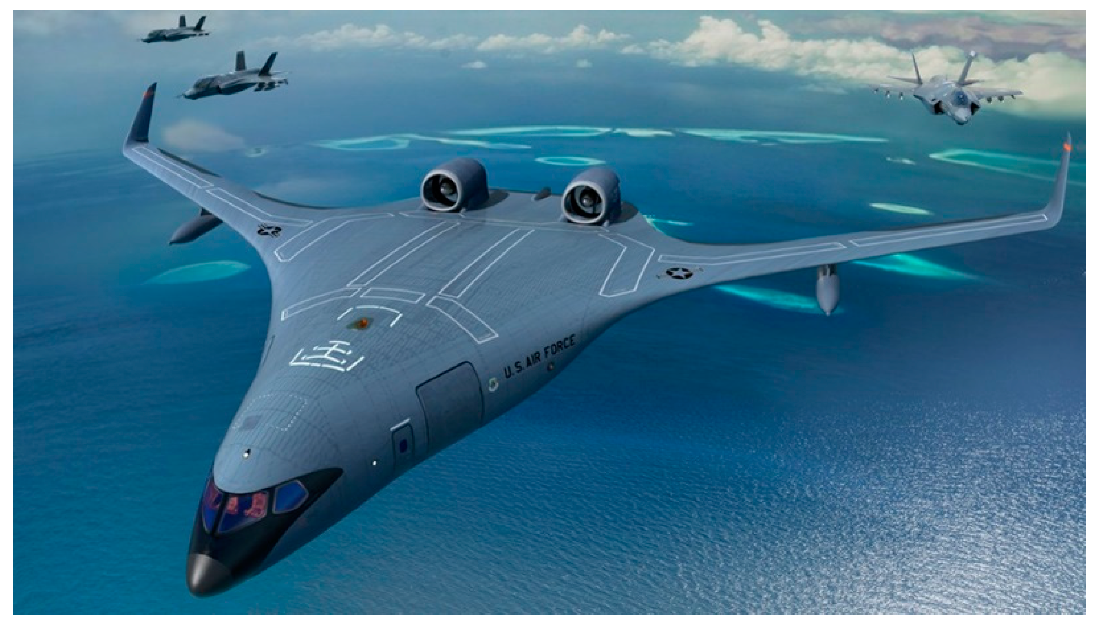
Despite the number of different propulsion alternatives, JetZero ultimately decided for a conventional design, placing conventional, high bypass turbofan engines on pylons at the rear section of the fuselage (Figure 12). Ultimately, it appears that the benefit of alternative propulsive alternatives is marginal compared to the design hurdles and cost of developing new technologies.
The only way the authors envision the NGAS aircraft to feature advanced concepts like embedded propulsion is if the U.S. Air Force places immense emphasis on stealth, like in the B-21 Raider. However, unlike the B-21 (which has to penetrate enemy territory undetected by air defenses), the NGAS will likely operate out of highly contested zones, where allied fighters can provide escort.
Obviously, the NGAS should still feature stealth elements and minimize noise/infrared emissions and radar scattering as much as possible, but embedded propulsion is likely not worth the additional complexity and cost.
2.5.2. Stealth
Flying wing/BWB designs have outstanding radar scattering characteristics due to the blended nature of the airframe [95], as well as the capacity to easily integrate radar absorbing materials [96] on the curvy fuselage. Overall, there is enormous potential to reduce the aircraft’s radar cross section (RCS), such as on the B-21 Raider.
Some other stealth elements have been previously discussed, such as noise (section 2.4) and infrared signature. There is a limit to reductions in infrared signature due to engine location. This may make the aircraft vulnerable to infrared search-and-track (IRST) systems of enemy fighter aircraft [97,98]. It is speculated that modern IRST systems can detect targets at around a 100 km distance [99], placing the enemy fighter well within radar range and beyond-visual-range (BVR) capability for escort fighters.
As explained in the previous section, the increased infrared signature is likely an acceptable compromise considering the design costs associated with burying the engines inside the fuselage.
2.5.3. Aircraft Safety, Passenger Comfort and Emergency Egress
Compliance with emergency egress rules is a major challenge for BWB configurations due to its shape and fuselage configuration [28]. For example, regulations state that the emergency exits must be above the waterline in case of a water landing [27]. Previous research has shown that the internal configuration of aisle widths, consisting of position, alignment and format is more important than the aircraft shape [56], and successful emergency egress can be achieved through proper design.
Another issue that can’t be easily alleviated through design is passenger comfort. In a blended configuration, most passengers do not direct vision over a window. Additionally, passengers away from the centerline are subject to higher g-loads over turns, deteriorating ride quality [25].
The authors opted to include these challenges to illustrate further design hurdles which contributed toward the BWB not entering commercial service. For a tanker aircraft such as the NGAS, the only “passengers” are the pilots and the refueling boom operator, rendering passenger-related issues a non-factor.
3. Conclusion
In this review paper, we discussed the history of blended wing body designs – from the early days of aviation to the successful B-2 Spirit bomber – highlighting its advantages and challenges and exploring the reasons why the BWB never entered into commercial service.
We firmly believe that the BWB, originally conceptualized as a long-haul transport aircraft, will likely become the U.S. Air Force Next-Generation Air-Refueling system (NGAS). The superior aerodynamic performance of the blended design allows it to fly further while burning less fuel, greatly enhancing refueling operations. The reduced radar signature, noise and infrared emissions are also particularly interesting for military application in highly contested airspace.
The technical advancements in the past three decades and unique features of tanker aircraft have put JetZero in great position to address the challenges that prevented the development of the BWB for passenger applications back in the 1990’s: for a tanker aircraft, passenger related issues are a non-factor; the development of new manufacturing techniques and materials greatly reduces the complexity of manufacturing complex shapes for the aircraft structure. Dealing with cabin pressure loads, which created major structural design hurdles in the past, is not necessary.
The last major issue to be addressed is stability and controls of the blended design. New technologies such as artificial intelligence present great potential to reduce design complexity. Also, this problem has been successfully tackled by Northrop Grumman in the development of the B-2 Spirit flying wing. Not so curiously, JetZero partnered with the company to manufacture the BWB tanker prototype. The existing know-how, added to (likely) major control updates for the new B-21 Raider bomber, puts JetZero in prime position to deal with these challenges.
It must be reinforced that the BWB is a highly coupled design, with numerous tradeoffs between aerodynamic performance, stability and controls, structural design and stealth characteristics, and a complex optimization process is necessary. Ultimately, time will show if the BWB tanker will enter serial production for the NGAS project. Its upcoming first flight, scheduled for 2027, will likely be the deciding factor.
References
- R. Wood and X. Bauer, “Flying wings/flying fuselages,” in 39th Aerospace Sciences Meeting and Exhibit, Reno, NV, U.S.A.: American Institute of Aeronautics and Astronautics, Jan. 2001. [CrossRef]
- H. [complied by] and R. D. A. [editor] Lukins, The book of Westland aircraft, First Edition. Aircraft Technical Pub, 1944.
- J. M. Campbell and G. R. Pape, Northrop Flying Wings: A History of Jack Northrop’s Visionary Aircraft, 1st edition. Atglen, PA: Schiffer Military History, 1997.
- D. Donald, The Encyclopedia of World Aircraft, 0 edition. Leicester: Bookmart, 1997.
- “The WW2 flying wing decades ahead of its time.” Accessed: Feb. 03, 2024. [Online]. Available: https://www.bbc.com/future/article/20160201-the-wwii-flying-wing-decades-ahead-of-its-time.
- D. Myhra, The Horten Brothers and Their All-Wing Aircraft, 1st ed. edition. Atglen, PA: Schiffer Military History, 1997.
- H. Griffiths, “The Horten Ho-229 Aircraft [History Column],” IEEE Aerospace and Electronic Systems Magazine, vol. 36, no. 1, pp. 61–61, Jan. 2021. [CrossRef]
- S. Magazine and R. Maksel, “Restoring Germany’s Captured ‘Bat Wing,’” Smithsonian Magazine. Accessed: Feb. 13, 2024. [Online]. Available: https://www.smithsonianmag.com/air-space-magazine/horten-flying-wing-180960066/.
- T. Coleman and R. Wenkam, Jack Northrop and the Flying Wing: The Story Behind the Stealth Bomber, First Edition. Paragon House, 1988.
- GAO/NSIAD-97-181, “B-2 Bomber: Cost and Operational Issues.” [Online]. Available: https://www.gao.gov/products/nsiad-97-181.
- J. Tirpak, “Second B-21 Under Construction as Bomber Moves Toward First Flight,” Air & Space Forces Magazine. Accessed: Feb. 03, 2024. [Online]. Available: https://www.airandspaceforces.com/second-b-21-under-construction-as-bomber-moves-toward-first-flight/.
- “The B-21 Raider: Designed For Low Risk | Aviation Week Network.” Accessed: Feb. 03, 2024. [Online]. Available: https://aviationweek.com/defense-space/aircraft-propulsion/b-21-raider-designed-low-risk.
- G. Times, “China’s long-range stealth bomber outlined in PLA Air Force recruitment video - Global Times.” Accessed: Feb. 03, 2024. [Online]. Available: https://www.globaltimes.cn/page/202101/1211986.shtml.
- B. I. Larrimer, Beyond tube-and-wing: The X-48 blended wing-body and NASA’s quest to reshape future transport aircraft. in NASA aeronautics book series. Washington, DC: NASA, 2020.
- R. H. Liebeck, “Design of the Blended Wing Body Subsonic Transport,” Journal of Aircraft, vol. 41, no. 1, pp. 10–25, 2004. [CrossRef]
- R. Martinez-Val, “Flying Wings. A New Paradigm for Civil Aviation?,” Acta Polytechnica, vol. 47, no. 1, Art. no. 1, Jan. 2007. [CrossRef]
- P. Okonkwo and H. Smith, “Review of evolving trends in blended wing body aircraft design,” Progress in Aerospace Sciences, vol. 82, pp. 1–23, Apr. 2016. [CrossRef]
- “Next Generation Air-refueling System (NGAS) Request for Information (RFI).” Accessed: Feb. 13, 2024. [Online]. Available: https://sam.gov/opp/b4a602a266e4450f861242c45e71fb07/view.
- J. Tirpak, “Air Force Launches New Stealthy Tanker Program, with Delivery Projected for 2040,” Air & Space Forces Magazine. Accessed: Oct. 08, 2023. [Online]. Available: https://www.airandspaceforces.com/air-force-launches-new-stealthy-tanker-program-with-delivery-projected-for-2040/.
- D. Roza, “As USAF Considers a Blended-Wing Body Tanker, New Startup Reveals Its Concept,” Air & Space Forces Magazine. Accessed: Oct. 08, 2023. [Online]. Available: https://www.airandspaceforces.com/air-force-blended-wing-body-tanker-jetzero/.
- “Start-up gets $235M investment from U.S. Air Force to help build sleek, futuristic-looking aircraft,” Fortune. Accessed: Oct. 08, 2023. [Online]. Available: https://fortune.com/2023/08/17/jetzero-us-air-force-investment/.
- G. Fernandes et al., “Conceptual Design of a Semi Blended Wing Body for the Air Force Next-Generation Air-Refueling System,” in AIAA SCITECH 2024 Forum, American Institute of Aeronautics and Astronautics. [CrossRef]
- R. Liebeck, M. Page, and B. Rawdon, “Blended-wing-body subsonic commercial transport,” in 36th AIAA Aerospace Sciences Meeting and Exhibit, in Aerospace Sciences Meetings. , American Institute of Aeronautics and Astronautics, 1998. [CrossRef]
- M. Kozek and A. Schirrer, Modeling and Control for a Blended Wing Body Aircraft: A Case Study. 2015. [CrossRef]
- R. Liebeck, “Blended Wing Body Design Challenges,” in AIAA International Air and Space Symposium and Exposition: The Next 100 Years, in International Air and Space Symposium (Evolution of Flight). , American Institute of Aeronautics and Astronautics, 2003. [CrossRef]
- D. Roman, R. Gilmore, and S. Wakayama, “Aerodynamics of High-Subsonic Blended-Wing-Body Configurations,” in 41st Aerospace Sciences Meeting and Exhibit, American Institute of Aeronautics and Astronautics, Jan. 2003. [CrossRef]
- L. Bolsunovsky et al., “Flying wing—Problems and decisions,” Aircraft Design, vol. 4, no. 4, pp. 193–219, Dec. 2001. [CrossRef]
- R. Liebeck, “Design of the Blended-Wing-Body subsonic transport,” in 40th AIAA Aerospace Sciences Meeting & Exhibit, American Institute of Aeronautics and Astronautics, Jan. 2002. [CrossRef]
- H. Smith, “College of Aeronautics Blended Wing Body Development Programme,” presented at the ICAS Congress, 2000.
- Morris, “MOB A European Distributed Multi-Disciplinary Design and Optimisation Project,” in 9th AIAA/ISSMO Symposium on Multidisciplinary Analysis and Optimization, American Institute of Aeronautics and Astronautics, Sep. 2002. [CrossRef]
- Morris, P. Arendsen, G. LaRocca, M. Laban, R. Voss, and H. Hönlinger, “MOB – A EUROPEAN PROJECT ON MULTIDISCIPLINARY DESIGN OPTIMISATION,” presented at the 24TH INTERNATIONAL CONGRESS OF THE AERONAUTICAL SCIENCES, 2004.
- M. Hepperle, “VELA 1 Baseline Configuration.” [Online]. Available: https://www.dlr.de/as/en/PortalData/5/Resources/dokumente/projekte/vela/The_VELA_Project.pdf.
- N. Qin, “Aerodynamic Studies for Blended Wing Body Aircraft,” in 9th AIAA/ISSMO Symposium on Multidisciplinary Analysis and Optimization, in Multidisciplinary Analysis Optimization Conferences. , American Institute of Aeronautics and Astronautics, 2002. [CrossRef]
- L. Moreno, R. Palma, and L. P. Pascual, “Aerodynamic study of a blended wing body, comparison with a conventional transport airplane.,” presented at the ICAS, Sep. 2006.
- P. Roysdon and M. Khalid, “Lateral-Directional Stability Investigation of a Blended-Wing Body,” in 10th AIAA Aviation Technology, Integration, and Operations (ATIO) Conference, in Aviation Technology, Integration, and Operations (ATIO) Conferences. , American Institute of Aeronautics and Astronautics, 2010. [CrossRef]
- J. Hileman, Z. Spakovszky, M. Drela, and M. Sargeant, “Aerodynamic and Aeroacoustic Three-Dimensional Design for a ‘Silent’ Aircraft,” in 44th AIAA Aerospace Sciences Meeting and Exhibit, in Aerospace Sciences Meetings. , American Institute of Aeronautics and Astronautics, 2006. [CrossRef]
- J. I. Hileman, Z. S. Spakovszky, M. Drela, M. A. Sargeant, and A. Jones, “Airframe Design for Silent Fuel-Efficient Aircraft,” Journal of Aircraft, vol. 47, no. 3, pp. 956–969, May 2010. [CrossRef]
- J. E. Green, “Greener by Design — the technology challenge,” The Aeronautical Journal, vol. 106, no. 1056, pp. 57–113, Feb. 2002. [CrossRef]
- S. Siouris and N. Qin, “Study of the effects of wing sweep on the aerodynamic performance of a blended wing body aircraft,” Proceedings of the Institution of Mechanical Engineers, Part G: Journal of Aerospace Engineering, vol. 221, no. 1, pp. 47–55, Jan. 2007. [CrossRef]
- S. Cho, C. Bil, and J. Bayandor, “Structural Design and Analysis of a BWB Military Cargo Transport Fuselage,” in 46th AIAA Aerospace Sciences Meeting and Exhibit, in Aerospace Sciences Meetings. , American Institute of Aeronautics and Astronautics, 2008. [CrossRef]
- D. Jung and M. Lowenberg, “Stability and Control Assessment of a Blended-Wing-Body Airliner Configuration,” presented at the AIAA Atmospheric Flight Mechanics Conference and Exhibit, American Institute of Aeronautics and Astronautics, Aug. 2005. [CrossRef]
- L. U. Hansen, W. Heinze, and P. Horst, “Blended wing body structures in multidisciplinary pre-design,” Struct Multidisc Optim, vol. 36, no. 1, pp. 93–106, Jul. 2008. [CrossRef]
- V. Mukhopadhyay, “Blended Wing Body (BWB) Fuselage Structural Design for Weight Reduction,” in 46th AIAA/ASME/ASCE/AHS/ASC Structures, Structural Dynamics and Materials Conference, Austin, Texas: American Institute of Aeronautics and Astronautics, Apr. 2005. [CrossRef]
- V. Mukhopadhyay, J. Sobieszczanski-Sobieski, I. Kosaka, G. Quinn, and G. N. Vanderplaats, “Analysis, Design, and Optimization of Noncylindrical Fuselage for Blended-Wing-Body Vehicle,” Journal of Aircraft, vol. 41, no. 4, pp. 925–930, Jul. 2004. [CrossRef]
- S. H. Cho, C. Bil, and J. Bayandor, “BWB Military Cargo Transport Fuselage Design and Analysis,” presented at the ICAS, 2008.
- M. Blair, G. Bharatram, and R. Canfield, “Designing a blended composite wing and fuselage,” presented at the 6th Symposium on Multidisciplinary Analysis and Optimization, American Institute of Aeronautics and Astronautics, 1996. [CrossRef]
- Velicki and P. Thrash, “Blended wing body structural concept development,” The Aeronautical Journal, vol. 114, no. 1158, pp. 513–519, Aug. 2010. [CrossRef]
- R. Vos, F. J. J. M. M. Geuskens, and M. F. M. Hoogreef, “A New Structural Design Concept for Blended Wing Body Cabins,” presented at the 53rd AIAA/ASME/ASCE/AHS/ASC Structures, Structural Dynamics and Materials Conference, Honolulu, Hawaii: American Institute of Aeronautics and Astronautics, Apr. 2012. [CrossRef]
- R. J. H. Wanhill, “Chapter 15 - Aerospace Applications of Aluminum–Lithium Alloys,” in Aluminum-lithium Alloys, N. Eswara Prasad, A. A. Gokhale, and R. J. H. Wanhill, Eds., Boston: Butterworth-Heinemann, 2014, pp. 503–535. [CrossRef]
- J. P. Moran, F. S. Bovard, J. D. Chrzan, and P. Vandenburgh, “Corrosion Performance of New Generation Aluminum-Lithium Alloys for Aerospace Applications,” in ICAA13 Pittsburgh, H. Weiland, A. D. Rollett, and W. A. Cassada, Eds., Cham: Springer International Publishing, 2016, pp. 425–430. [CrossRef]
- R. Langton, C. Clark, M. Hewitt, L. Richards, I. Moir, and A. Seabridge, Aircraft Fuel Systems, 1st edition. Chichester, U.K: Wiley, 2009.
- Y. Denieul, J. Bordeneuve, D. Alazard, C. Toussaint, and G. Taquin, “Multicontrol Surface Optimization for Blended Wing–Body Under Handling Quality Constraints,” Journal of Aircraft, vol. 55, no. 2, pp. 638–651, 2018. [CrossRef]
- W. Tung and B.-C. Song, “Aerodynamic Performance Study of a Modern Blended-Wing-Body Aircraft Under Severe Weather Situations,” in 49th AIAA Aerospace Sciences Meeting including the New Horizons Forum and Aerospace Exposition, in Aerospace Sciences Meetings. , American Institute of Aeronautics and Astronautics, 2011. [CrossRef]
- T. Wan and H. Yang, “Aerodynamic Performance Investigation of a Modern Blended-Wing-Body Aircraft Under the Influence of Heavy Rain Condition,” presented at the ICAS, 2010.
- D. Cameron and N. Princen, “Control allocation challenges and requirements for the Blended Wing Body,” in AIAA Guidance, Navigation, and Control Conference and Exhibit, in Guidance, Navigation, and Control and Co-located Conferences. , American Institute of Aeronautics and Astronautics, 2000. [CrossRef]
- “Final Report Summary - NACRE (New aircraft concepts research) | FP6,” CORDIS | European Commission. Accessed: Feb. 03, 2024. [Online]. Available: https://cordis.europa.eu/project/id/516068/reporting.
- M. Voskuijl, G. L. Rocca, and F. Dircken, “Controllability of Blended Wing Body Aircraft,” presented at the ICAS, 2008.
- R. Nangia and M. Palmer, “Flying-Wings (Blended Wing Bodies) with Aft & Forward Sweep, Relating Design Camber & Twist to Longitudinal Control,” presented at the AIAA Atmospheric Flight Mechanics Conference and Exhibit, American Institute of Aeronautics and Astronautics, Aug. 2002. [CrossRef]
- Wildschek, T. Havar, and K. Plötner, “An all-composite, all-electric, morphing trailing edge device for flight control on a blended-wing-body airliner,” Proceedings of The Institution of Mechanical Engineers Part G-journal of Aerospace Engineering - PROC INST MECH ENG G-J A E, vol. 224, pp. 1–9, Jan. 2010. [CrossRef]
- S. M. Waters, M. Voskuijl, L. L. M. Veldhuis, and F. J. J. M. M. Geuskens, “Control allocation performance for blended wing body aircraft and its impact on control surface design,” Aerospace Science and Technology, vol. 29, no. 1, pp. 18–27, Aug. 2013. [CrossRef]
- Y. Staelens, R. Blackwelder, and M. Page, “Novel Pitch Control Effectors for a Blended Wing Body Airplane in Takeoff and Landing Configuration,” presented at the 45th AIAA Aerospace Sciences Meeting and Exhibit, American Institute of Aeronautics and Astronautics, Jan. 2007. [CrossRef]
- Schirrer, C. Westermayer, M. Hemedi, and M. Kozek, “LQ-based design of the inner loop lateral control for a large flexible BWB-type aircraft,” in 2010 IEEE International Conference on Control Applications, Sep. 2010, pp. 1850–1855. [CrossRef]
- Valiyff and M. Arjomandi, “An Investigation Into the Aerodynamic Efficiency of Tailles Aircraft,” presented at the 47th AIAA Aerospace Sciences Meeting including The New Horizons Forum and Aerospace Exposition, American Institute of Aeronautics and Astronautics, Jan. 2009. [CrossRef]
- R. Martínez-Val, E. Pérez, P. Alfaro, and J. Pérez, “Conceptual design of a medium size flying wing,” Proceedings of the Institution of Mechanical Engineers, Part G: Journal of Aerospace Engineering, vol. 221, no. 1, pp. 57–66, Jan. 2007. [CrossRef]
- Agarwal, A. P. Dowling, H.-C. Shin, W. Graham, and S. Sefi, “Ray Tracing Approach to Calculate Acoustic Sheilding by a Flying Wing Airframe,” AIAA Journal, vol. 45, no. 5, pp. 1080–1090, May 2007. [CrossRef]
- L. Clark and C. Gerhold, “Inlet noise reduction by shielding for the blended-wing-body airplane,” in 5th AIAA/CEAS Aeroacoustics Conference and Exhibit, Bellevue,WA,U.S.A.: American Institute of Aeronautics and Astronautics, May 1999. [CrossRef]
- G. A. Hill and R. H. Thomas, “Challenges and Opportunities for Noise Reduction Through Advanced Aircraft Propulsion Airframe Integration and Configurations,” presented at the 8th CEAS Workshop, 2004.
- G. Hill, S. Brown, K. Geiselhart, and C. Burg, “Integration of Propulsion-Airframe-Aeroacoustic Technologies and Design Concepts for a Quiet Blended-Wing-Body Transport,” in AIAA 4th Aviation Technology, Integration and Operations (ATIO) Forum, Chicago, Illinois: American Institute of Aeronautics and Astronautics, Sep. 2004. [CrossRef]
- Diedrich, J. Hileman, D. Tan, K. Willcox, and Z. Spakovszky, “Multidisciplinary Design and Optimization of the Silent Aircraft,” in 44th AIAA Aerospace Sciences Meeting and Exhibit, in Aerospace Sciences Meetings. , American Institute of Aeronautics and Astronautics, 2006. [CrossRef]
- L. T. Leifsson, “Multidisciplinary Design Optimization of Low-Noise Transport Aircraft,” Virginia Tech University, Blacksburg, VA, 2005.
- Y. Guo, C. L. Burley, and R. H. Thomas, “On Noise Assessment for Blended Wing Body Aircraft,” in 52nd Aerospace Sciences Meeting, National Harbor, Maryland: American Institute of Aeronautics and Astronautics, Jan. 2014. [CrossRef]
- S. Wakayama, “Blended-wing-body optimization problem setup,” presented at the 8th Symposium on Multidisciplinary Analysis and Optimization, American Institute of Aeronautics and Astronautics, Sep. 2000. [CrossRef]
- Quayle, A. Dowling, H. Babinsky, H.-C. Shin, W. Graham, and P. Sijtsma, “Landing Gear for a Silent Aircraft,” presented at the 45th AIAA Aerospace Sciences Meeting and Exhibit, American Institute of Aeronautics and Astronautics, Jan. 2007. [CrossRef]
- D. Crichton, E. de la Rosa Blanca, T. Law, and J. Hileman, “Design and Operation for Ultra Low Noise Take-Off,” in 45th AIAA Aerospace Sciences Meeting and Exhibit, in Aerospace Sciences Meetings. , American Institute of Aeronautics and Astronautics, 2007. [CrossRef]
- “Silent Aircraft Initiative Concept Risk Assessment - NASA Technical Reports Server (NTRS).” Accessed: Feb. 01, 2024. [Online]. Available: https://ntrs.nasa.gov/citations/20080012497.
- T. Law and A. Dowling, “Optimisation of Traditional and Blown Liners for a Silent Aircraft,” in 12th AIAA/CEAS Aeroacoustics Conference (27th AIAA Aeroacoustics Conference), Cambridge, Massachusetts: American Institute of Aeronautics and Astronautics, May 2006. [CrossRef]
- Reimann, A. Tinetti, and M. Dunn, “Noise Scattering by the Blended Wing Body Airplane: Measurements and Prediction,” in 12th AIAA/CEAS Aeroacoustics Conference (27th AIAA Aeroacoustics Conference), in Aeroacoustics Conferences. , American Institute of Aeronautics and Astronautics, 2006. [CrossRef]
- K. Sakaliyski, J. Hileman, and Z. Spakovszky, “Aero-Acoustics of Perforated Drag Plates for Quiet Transport Aircraft,” in 45th AIAA Aerospace Sciences Meeting and Exhibit, in Aerospace Sciences Meetings. , American Institute of Aeronautics and Astronautics, 2007. [CrossRef]
- P. Shah, D. Mobed, and Z. Spakovszky, “Engine Air-Brakes for Quiet Air Transport,” presented at the 45th AIAA Aerospace Sciences Meeting and Exhibit, American Institute of Aeronautics and Astronautics, Jan. 2007. [CrossRef]
- M. Herr and W. Dobrzynski, “Experimental Investigations in Low-Noise Trailing Edge Design.,” AIAA Journal, vol. 43, no. 6, pp. 1167–1175, Jun. 2005. [CrossRef]
- R. H. Thomas, C. L. Burley, and E. D. Olson, “Hybrid Wing Body Aircraft System Noise Assessment with Propulsion Airframe Aeroacoustic Experiments,” International Journal of Aeroacoustics, vol. 11, no. 3–4, pp. 369–409, Sep. 2012. [CrossRef]
- Y. Guo and R. H. Thomas, “System Noise Assessment of Blended-Wing-Body Aircraft with Open Rotor Propulsion,” in 53rd AIAA Aerospace Sciences Meeting, Kissimmee, Florida: American Institute of Aeronautics and Astronautics, Jan. 2015. [CrossRef]
- M. D. Guynn, J. E. Freeh, and E. D. Olson, “Evaluation of a Hydrogen Fuel Cell Powered Blended-Wing-Body Aircraft Concept for Reduced Noise and Emissions,” 2004.
- Guynn and E. D. Oison, “Reduced Noise and Emissions,” NASA Langley Research Center, Technical Memorandum 20020079419, Sep. 2002. [Online]. Available: https://ntrs.nasa.gov/citations/20020079419.
- Hall and D. Crichton, “Engine And Installation Configurations For A Silent Aircraft,” presented at the XVII International Symposium on Air Breathing Engines, Munich, Germany, Sep. 2005.
- L. Nickol, “Silent Aircraft Initiative Concept Risk Assessment,” NASA Langley Research Center, Technical Memorandum 20080012497, Feb. 2008. [Online]. Available: https://ntrs.nasa.gov/citations/20080012497.
- Reimann, A. Tinetti, and M. Dunn, “Noise Prediction Studies for the Blended Wing Body Using the Fast Scattering Code,” in 11th AIAA/CEAS Aeroacoustics Conference, in Aeroacoustics Conferences. , American Institute of Aeronautics and Astronautics, 2005. [CrossRef]
- Proudman and G. I. Taylor, “The generation of noise by isotropic turbulence,” Proceedings of the Royal Society of London. Series A. Mathematical and Physical Sciences, vol. 214, no. 1116, pp. 119–132, Jan. 1997. [CrossRef]
- R. Pieren et al., “Perception-based noise assessment of a future blended wing body aircraft concept using synthesized flyovers in an acoustic VR environment—The ARTEM study,” Aerospace Science and Technology, vol. 144, p. 108767, Jan. 2024. [CrossRef]
- N. Gandur et al., “Conceptual Design of a Single Core Mixed Pressure Flow Hybrid Electric Turbine Engine,” in AIAA SCITECH 2024 Forum, American Institute of Aeronautics and Astronautics. [CrossRef]
- M. B. Carter, R. L. Campbell, O. C. Pendergraft, D. M. Friedman, and L. Serrano, “Designing and Testing a Blended Wing Body with Boundary-Layer Ingestion Nacelles,” Journal of Aircraft, vol. 43, no. 5, pp. 1479–1489, Sep. 2006. [CrossRef]
- R. T. Kawai, D. M. Friedman, and L. Serrano, “Blended Wing Body (BWB) Boundary Layer Ingestion (BLI) Inlet Configuration and System Studies,” NASA/CR-2006-214534, Dec. 2006. Accessed: Feb. 28, 2024. [Online]. Available: https://ntrs.nasa.gov/citations/20070006754.
- Hileman, Z. Spakovszky, M. Drela, and M. Sargeant, “Airframe Design for ‘Silent Aircraft,’” in 45th AIAA Aerospace Sciences Meeting and Exhibit, Reno, Nevada: American Institute of Aeronautics and Astronautics, Jan. 2007. [CrossRef]
- Q. Yang, Y. Zheng, and T. Streit, “Aerodynamic Design for Wing-Body Blended and Inlet,” presented at the ICAS, 2006.
- M. Li, J. Bai, L. Li, X. Meng, Q. Liu, and B. Chen, “A gradient-based aero-stealth optimization design method for flying wing aircraft,” Aerospace Science and Technology, vol. 92, pp. 156–169, Sep. 2019. [CrossRef]
- N. Shirke, V. Ghase, and V. Jamdar, “Recent advances in stealth coating,” Polym. Bull., Feb. 2024. [CrossRef]
- S. P. Mahulikar, H. R. Sonawane, and G. Arvind Rao, “Infrared signature studies of aerospace vehicles,” Progress in Aerospace Sciences, vol. 43, no. 7, pp. 218–245, Oct. 2007. [CrossRef]
- H. B. Srivastava, Y. B. Limbu, R. Saran, and A. Kumar, “Airborne Infrared Search and Track Systems,” Defence Science Journal, vol. 57, no. 5, Art. no. 5, Sep. 2007. [CrossRef]
- “Bundesheer - TRUPPENDIENST - Ausgabe 6/2008 - Der Eurofighter ‘Typhoon’ (VII).” Accessed: Feb. 29, 2024. [Online]. Available: https://www.bmlv.gv.at/truppendienst/ausgaben/artikel.php?id=807.
Figure 1.
Northrop N-1M “Jeep” flying wing (Courtesy of Smithsonian National Air and Space Museum. Available at https://airandspace.si.edu/collection-media/NASM-NASM2015-04014).
Figure 1.
Northrop N-1M “Jeep” flying wing (Courtesy of Smithsonian National Air and Space Museum. Available at https://airandspace.si.edu/collection-media/NASM-NASM2015-04014).
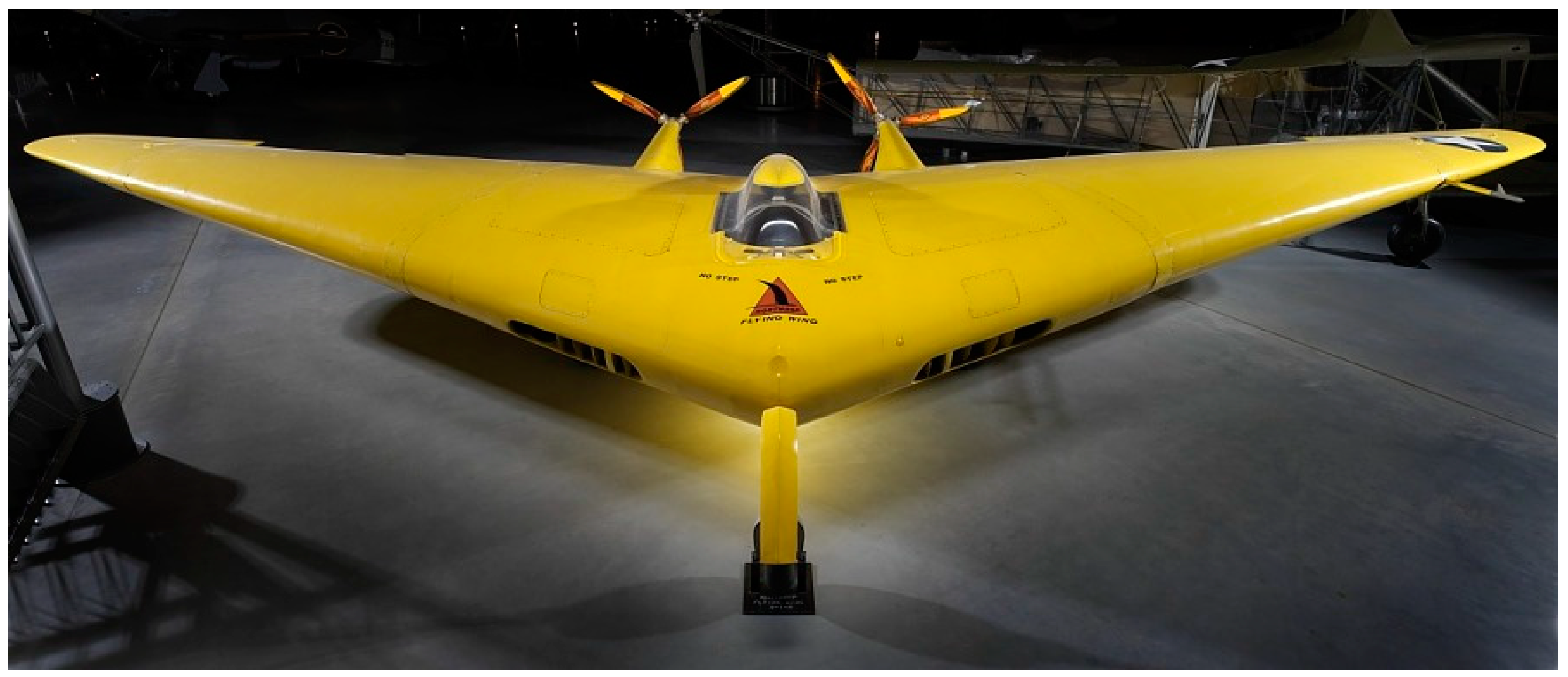
Figure 2.
The Ho 229 in flight. Source: [7].
Figure 2.
The Ho 229 in flight. Source: [7].
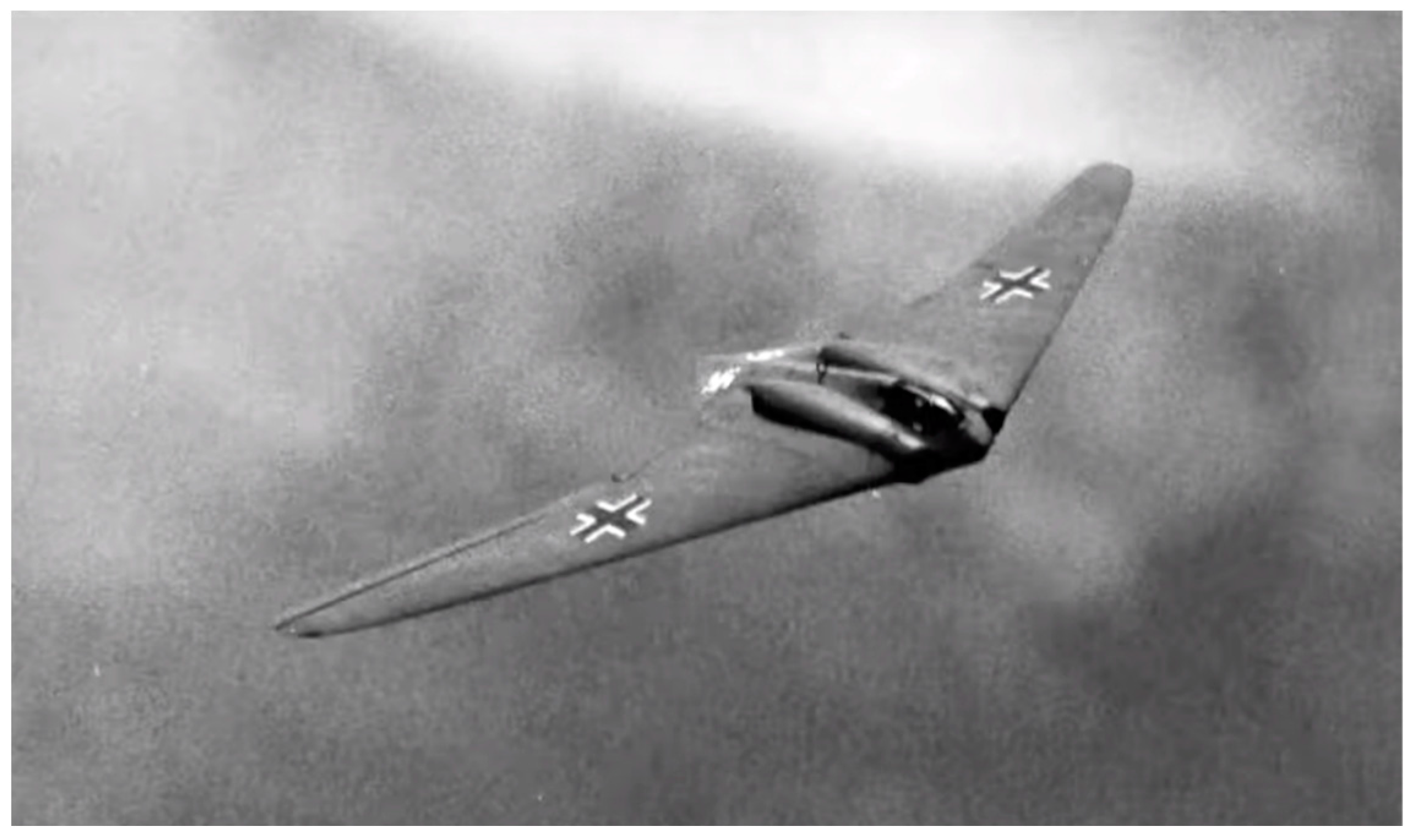
Figure 3.
B-21 Raider stealth bomber. Courtesy of the U.S. Air Force.
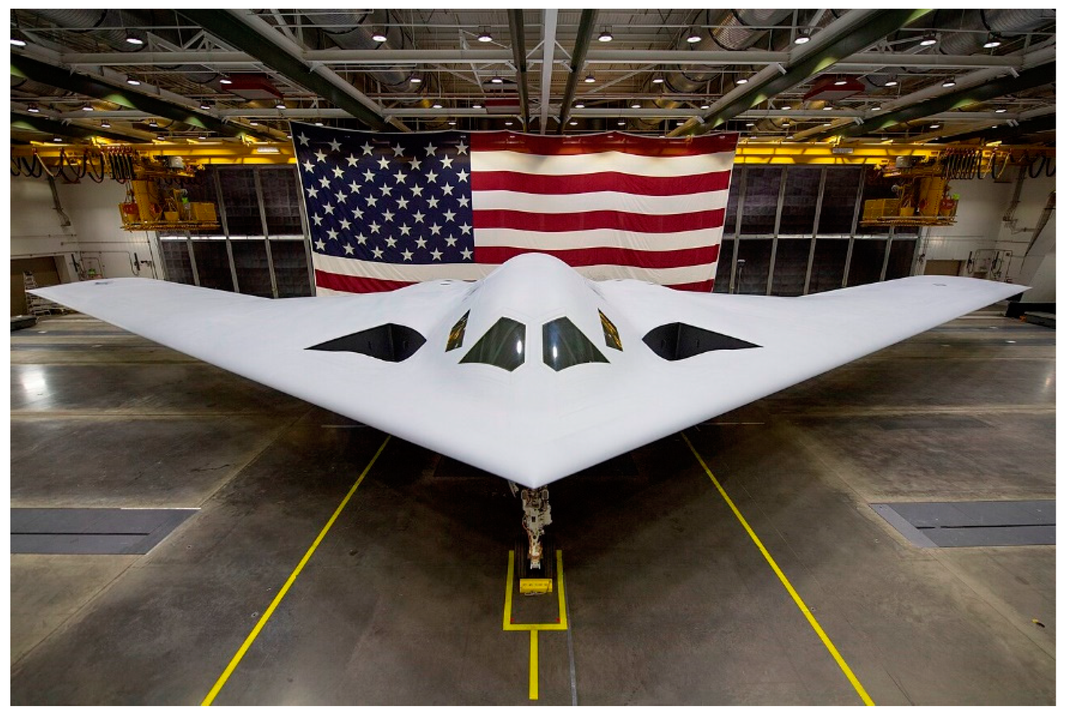
Figure 4.
Early BWB design [15].
Figure 4.
Early BWB design [15].
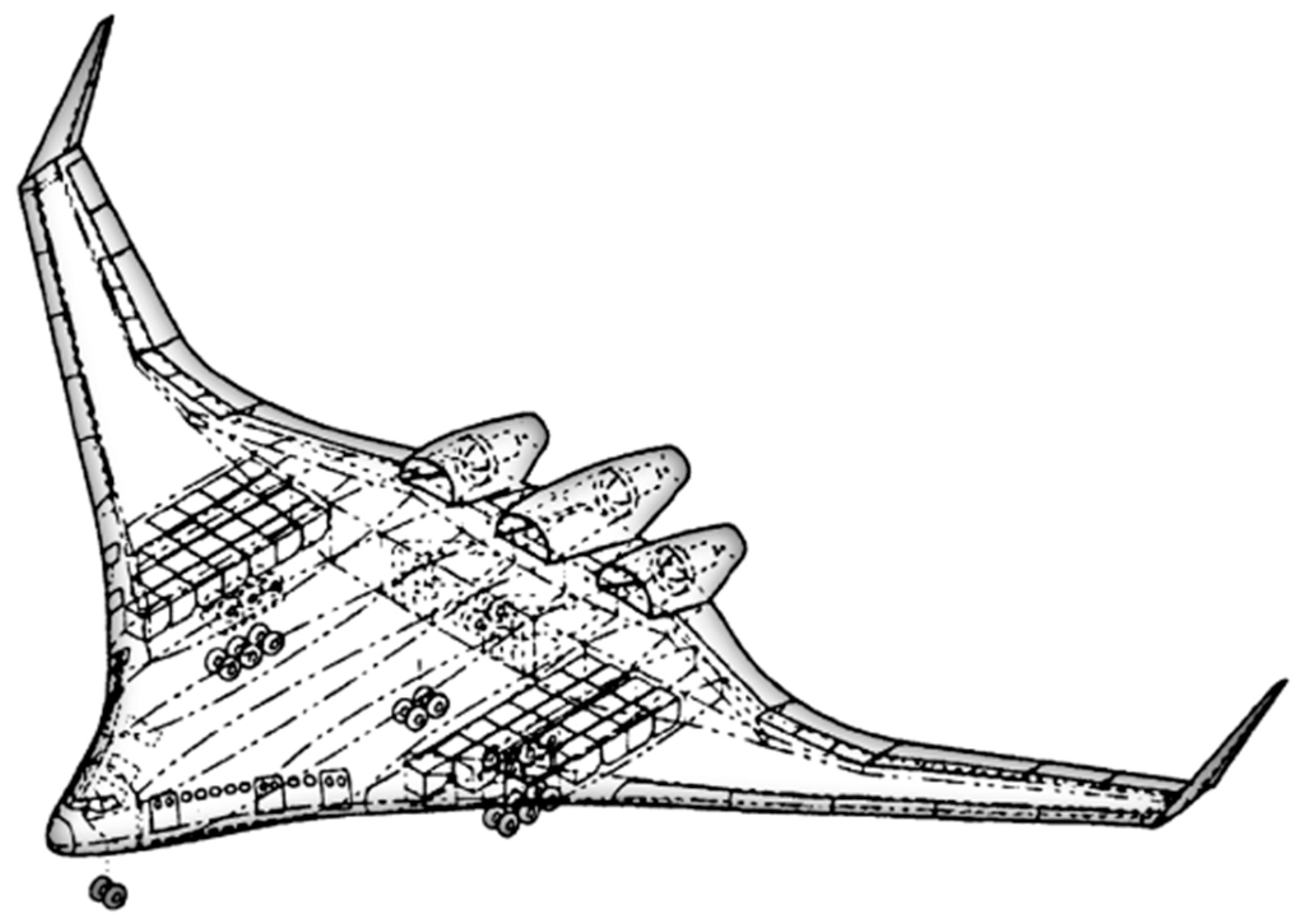
Figure 5.
Artist impression of Blended Wing body tanker aircraft (Courtesy of JetZero).
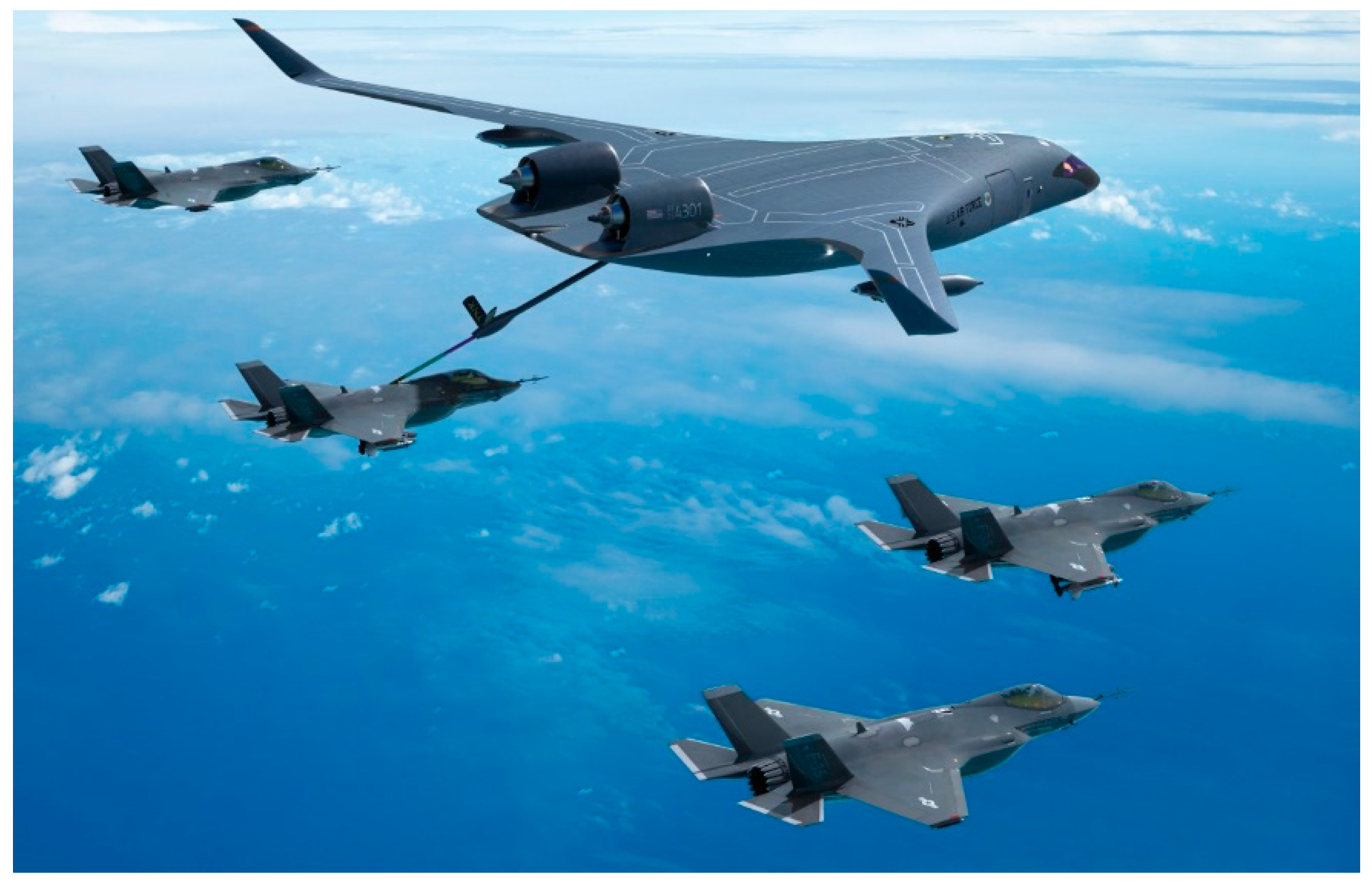
Figure 6.
Early structural concepts for centerbody BWB [28].
Figure 6.
Early structural concepts for centerbody BWB [28].
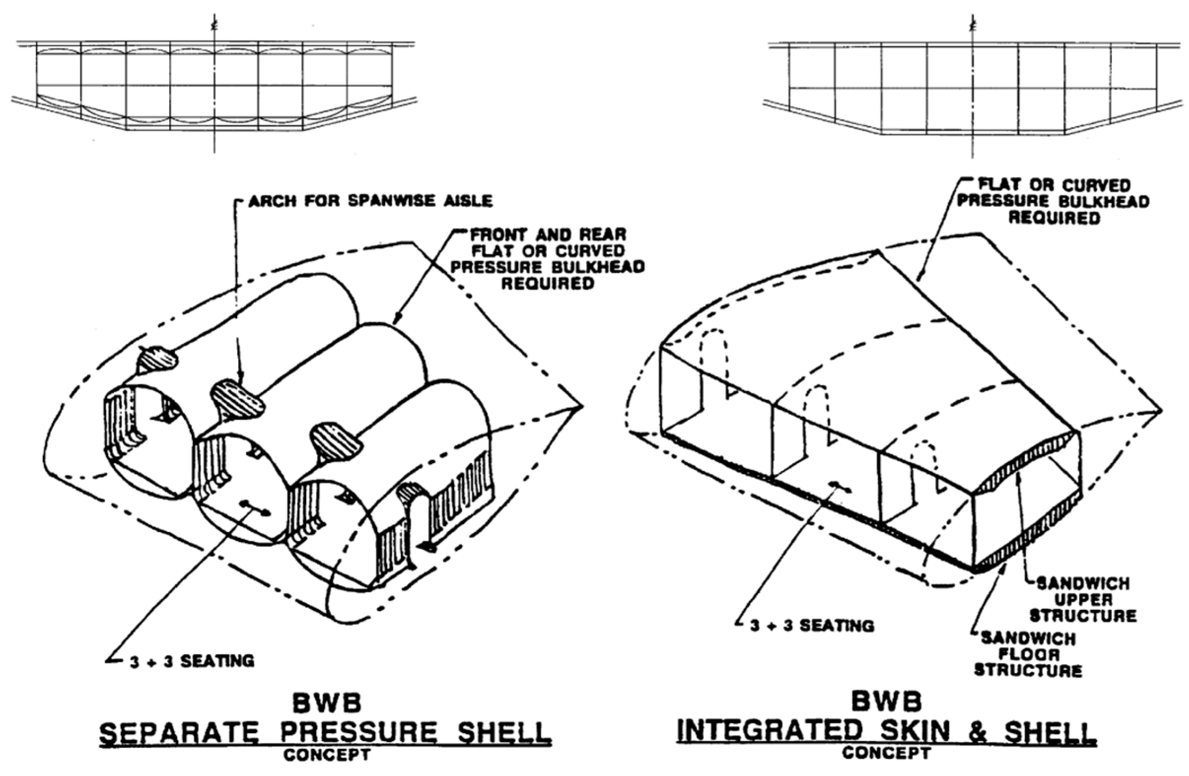
Figure 7.
FEA analysis of multi-bubble concept fuselage (MBF) loaded with cabin pressure and simulated aerodynamic loadings [43].
Figure 7.
FEA analysis of multi-bubble concept fuselage (MBF) loaded with cabin pressure and simulated aerodynamic loadings [43].
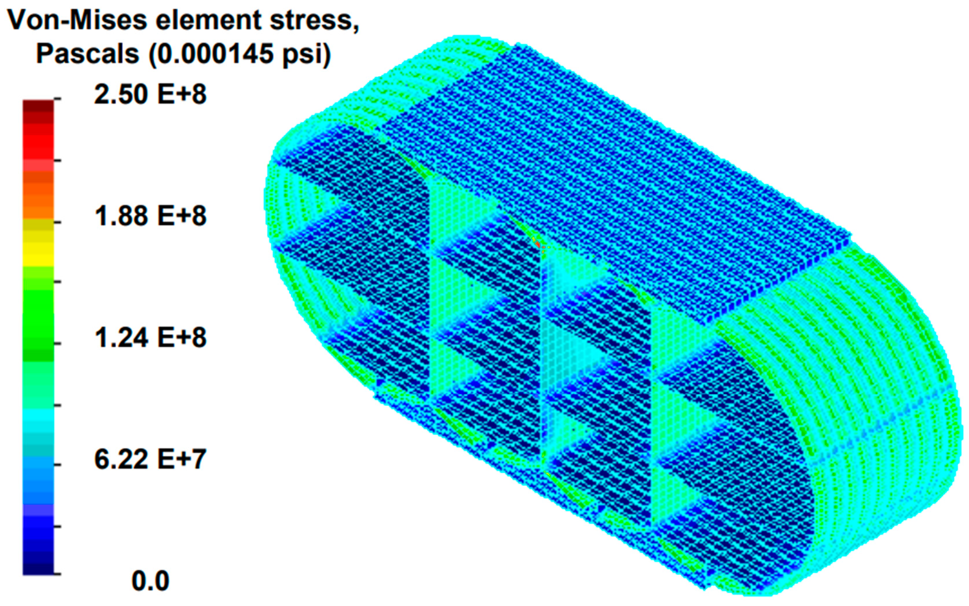
Figure 8.
Optimized CMBF structure for center body BWB [45].
Figure 8.
Optimized CMBF structure for center body BWB [45].
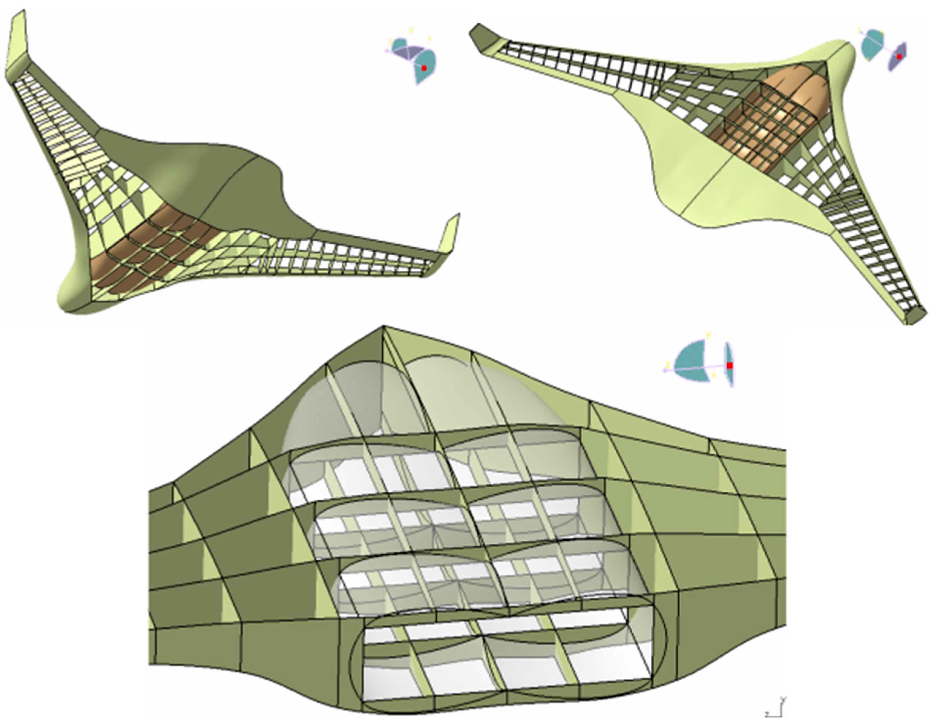
Figure 9.
Y-braced box fuselage for BWB vehicle [43].
Figure 9.
Y-braced box fuselage for BWB vehicle [43].
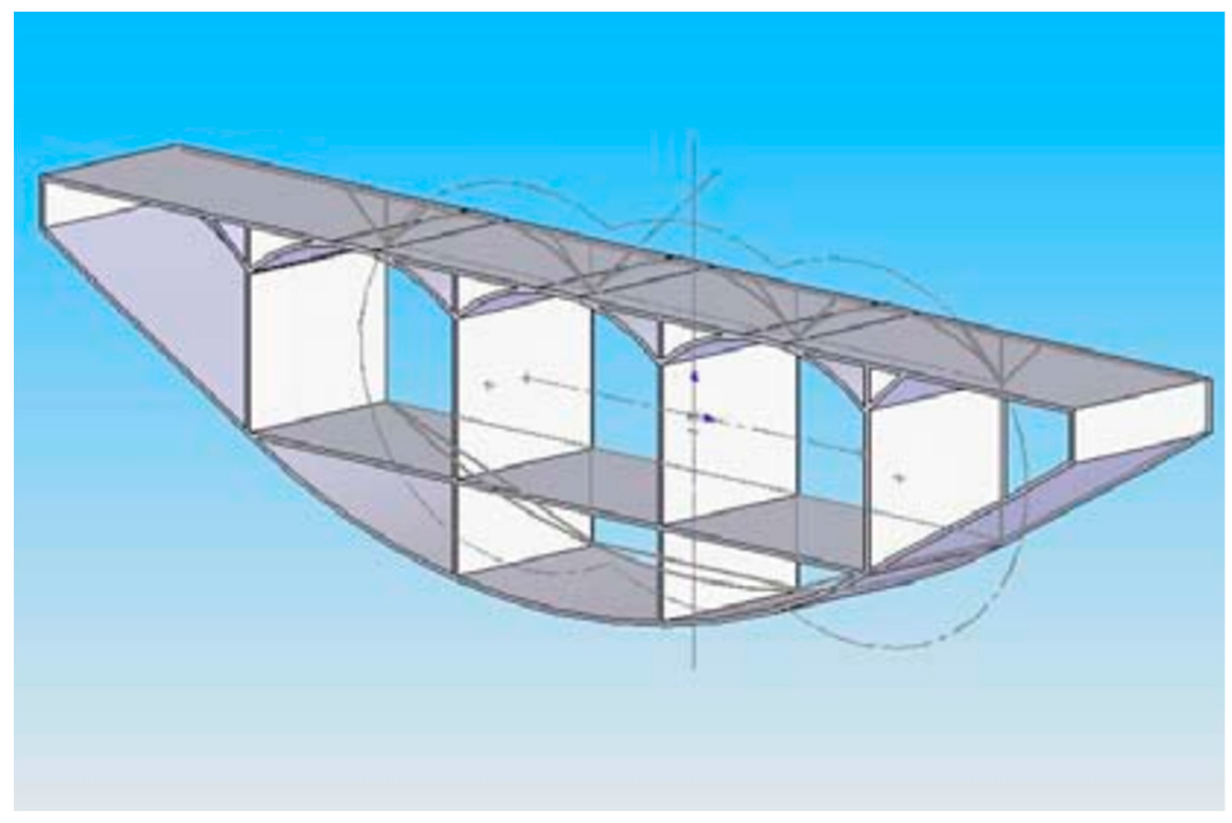
Figure 10.
Moment behavior of select blended wing body configurations [27].
Figure 10.
Moment behavior of select blended wing body configurations [27].
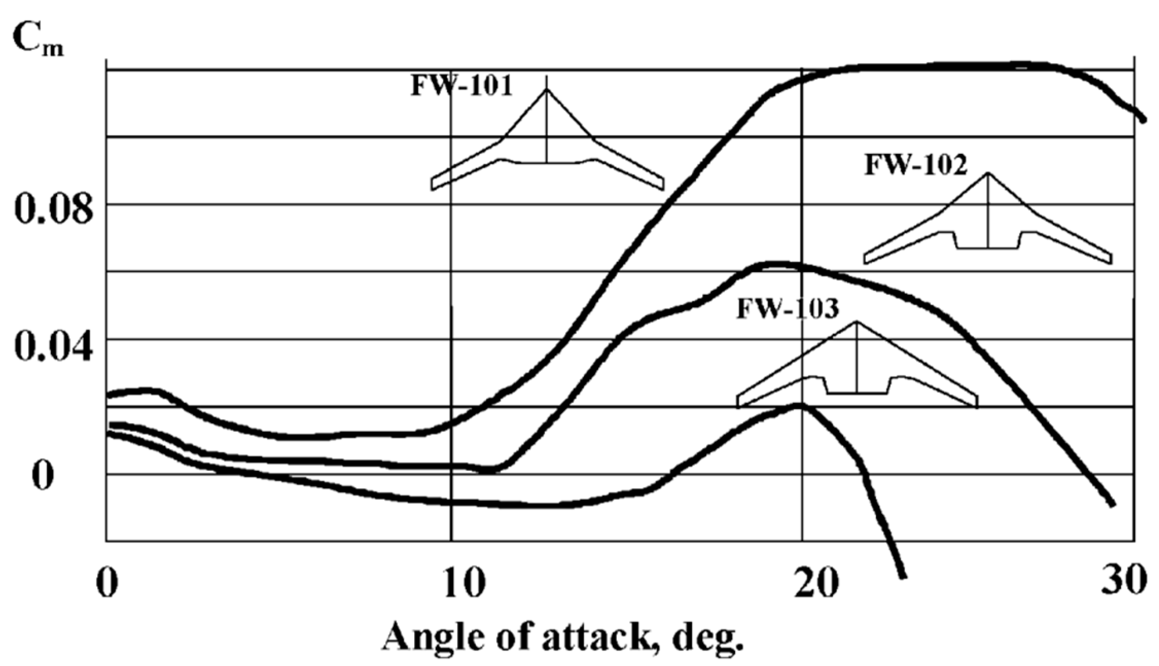
Figure 11.
Morphing trailing edge device in aileron mode [59].
Figure 11.
Morphing trailing edge device in aileron mode [59].
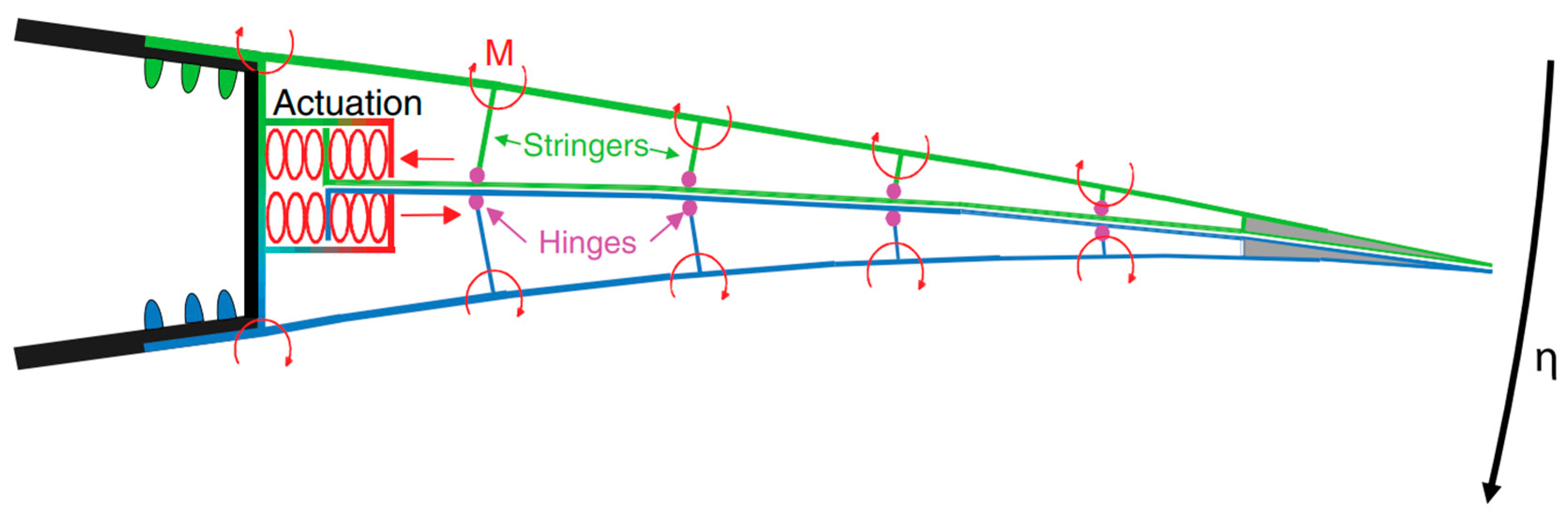
Figure 12.
Artist conception of the NGAS during mission. (Courtesy of Jetzero).
Disclaimer/Publisher’s Note: The statements, opinions and data contained in all publications are solely those of the individual author(s) and contributor(s) and not of MDPI and/or the editor(s). MDPI and/or the editor(s) disclaim responsibility for any injury to people or property resulting from any ideas, methods, instructions or products referred to in the content. |
© 2024 by the authors. Licensee MDPI, Basel, Switzerland. This article is an open access article distributed under the terms and conditions of the Creative Commons Attribution (CC BY) license (http://creativecommons.org/licenses/by/4.0/).
Copyright: This open access article is published under a Creative Commons CC BY 4.0 license, which permit the free download, distribution, and reuse, provided that the author and preprint are cited in any reuse.


