
Submitted:
29 April 2024
Posted:
30 April 2024
You are already at the latest version
Abstract
Это исследование сосредоточено на разработке системы искусственного зрения для гибкого дельта-робота-манипулятора и ее интеграции с межмашинной связью для оптимизации взаимодействия устройств в реальном времени. Эта интеграция направлена на увеличение скорости роботизированной системы и улучшение ее общей производительности. Предлагаемое сочетание системы искусственного зрения с межмашинной связью позволяет обнаруживать и распознавать цели с высокой точностью в режиме реального времени в ограниченном пространстве, предназначенном для позиционирования, дальнейшей локализации и выполнения производственных процессов, таких как сборка или сортировка деталей. . В данном исследовании RGB-изображения используются в качестве входных данных для алгоритма MASK-R-CNN, а результаты обрабатываются в соответствии с особенностями прототипа дельта-манипулятора робота. Данные, полученные от MASK-R-CNN, адаптированы для использования в системе управления дельта-роботом с учетом ее уникальных характеристик и требований к позиционированию. Технология M2M позволяет манипулятору робота быстро реагировать на изменения, например, на перемещение объектов или изменение их положения, что имеет решающее значение для задач сортировки и упаковки. Система была протестирована в условиях, близких к реальным, чтобы оценить ее производительность и надежность.
Keywords:
machine-to-machine communication
; delta robot manipulator
; artificial vision system
; RGB
; MASK-R-CNN
1. Introduction
Presently, the widespread adoption of artificial intelligence (AI) with various robotic systems to mimic human intelligence has triggered tremendous changes in today’s technological environment and the activities of humanity as a whole.
Over the past decades, elements of artificial intelligence, using techniques such as machine learning, deep learning, cognitive computing, etc. have made significant progress in creating a variety of applications and robotic systems that can perceive, analyze, and process incoming information, including decision-making autonomously without human intervention in various fields of activity such as logistics, transport, surveillance systems, automated complexes, health care and science [1].
The concept of applying artificial intelligence is justified as an interdisciplinary and complex technology to create intelligent robotic systems. This is justified by the fact that it combines different technologies that can operate as independent systems and also in combination with various Internet of Things (IoT) devices, allowing remote control of systems or devices through mobile control platforms. The complexity of intelligent robotic systems technology also lies in the integration and interaction between control, monitoring, and automation systems, including centralized data storage and processing and production facilities, which in turn must have properties such as self-awareness, self-prediction, self-comparison, self-configuration, self-service, organization of the process being performed and a sufficient level of sustainability without human involvement in the intelligent production process. This trend in the formation of intelligent robotic systems leads to the development of new approaches to industrial production based on the process of generation, as well as processes using AI elements of machine vision, and computer vision, which raises the relevance of research in the field of generation and detection of objects using elements of artificial vision without human participation.
In a broad understanding, the main role of artificial vision in modern intelligent robotic systems is to interpret obtained visual data, including processes such as object recognition, tracking, and image segmentation [2]. Currently, the effectiveness of image classification, object detection, and segmentation algorithms strongly depends on the analysis of visual data and its spatial patterns, including real-time data processing. The integration of complex data acquisition systems, processing algorithms, and computational complexity requires significant time and computational resources [3].
Various image augmentation techniques can be applied to simplify the process and prevent over-learning. These methods include modifications such as rotating, cropping, rotating, resizing, adding noise, random erasure, combining images, and other similar techniques. However, most robotic systems have insufficient data storage capacity and computational power, which makes the solution to this problem more urgent.
The combination of artificial intelligence algorithms with Internet of Things (IoT) devices is also popular. This approach is based on deployed deep or machine learning models that allow the processing of incoming visual data and analyzing it, including making decisions collaboratively or independently without human intervention [4]. In this case, storage in the form of a cloud server equipped with neural networks is introduced into the Internet of Things environment to perform the functions of load balancing of visual data for storage and processing, as well as to perform computational operations, which contributes as an assistant in analyzing the input data received from intelligent devices. This kind of interconnection between IoT devices and various servers is defined as “machine-to-machine communication” (M2M), which today is becoming more dominant than the interconnection between a human and an intelligent device or machine.
In today’s world, artificial vision and machine-to-machine communication play a vital role in the development of robotics and the automation of industrial and domestic processes. Artificial vision, as a key component of artificial intelligence, gives robots and automated systems the ability to perceive and analyze their surroundings using cameras, sensors, and other devices. M2M, on the other hand, allows these systems to share data and information, opening up new possibilities for network coordination and collaboration. Despite significant advances in artificial vision and machine-to-machine communication, many challenges in the development of intelligent robotic systems still exist for developers and researchers.
This research aims to develop an artificial vision system for a robotic device like the Delta robot - a manipulator using Machine-to-Machine technologies. Specific objectives of the research include studying the possibilities and advantages of M2M technologies for Delta robot manipulator operation, developing algorithms for image processing and data analysis, and creating an intelligent control system to coordinate the actions of the Delta robot manipulator based on the information received from the artificial vision system. The research results can be applied in various fields, including manufacturing, medicine, service, and education.
In the course of the research implementation, the authors review the latest trends and achievements in the development of artificial vision systems in robotic systems using M2M technologies. Also, the paper details the principles of the combined operation of the artificial vision system and machine-to-machine communication, including their role in the creation of autonomous robots and intelligent control systems based on the developed prototype delta robot - -manipulator by the authors [5].
In [5], the authors created a robotic system consisting of a fixed and mobile platform with three axes of freedom to move in a limited space, perform grasping operations, and function at high speed. Delta robot arms of this type have found wide application in the industrial sector, in areas such as sorting of objects/parts, assembly processes, and other operations where fast movement in three-dimensional space is a key factor. Today, they are also used in medical and pharmaceutical processes, as well as in the production of electronics and other high-precision products.
Considering the peculiarities of the positioning of the proposed flexible robot and the key forward and inverse kinematic parameters, the development proposed in the paper by the authors [5] was intended to conduct research on the creation of a machine vision system with an intelligent control system for its further optimal positioning and application in sorting processes.
This research on the development of an artificial vision system for a delta manipulator robot includes several key steps necessary to achieve the objective:
1. Development of computer vision algorithms for object recognition and image processing. This stage includes the development of algorithms for processing images obtained from the camera located in the delta robot manipulator, realized by studying algorithms for object detection, pattern detection, and motion identification. For this purpose, this paper applies the methods of machine learning and computer vision.
2. Development of a delta robot manipulator control system. In this stage, a control system is developed that will use image processing algorithms to control the motion and positioning of the robot. The control system developed should be able to take input data from the camera, process it using algorithms, and then send commands to move the robot.
3. Integration of the artificial vision system with the M2M-based robot control system to fulfill the specified tasks. This stage involves integrating the created artificial vision algorithm with a complex delta robot arm control system. The integration of the systems should be able to control the robot’s motion in such a way that it can respond to visual stimuli with high speed and accuracy while respecting the forward and backward kinematics of the robot’s operation.
4.Testing and debugging the artificial vision system in real robot working conditions. This stage includes the experimental study of the delta robot manipulator.
2. Related Work
Automation of production processes with the use of robotic systems provides many advantages in replacing the role of humans in reliable detection and rapid manipulation of various production processes [6]. To date, the research interest of scientists around the world is focused on the development of intelligent robotic systems that can be used in various types of industrial and domestic activities of mankind, the effectiveness of which is confirmed with less consumption of resources for their maintenance and training processes. The most important factor in the development of intelligent robots is in the criteria for ensuring high reliability and flexibility of the system being developed, as well as in the development of an effective system of adaptation to different circumstances and requirements. In this case, the introduction of artificial intelligence in the robotic system helps developers to increase the productivity of the process by reducing energy consumption for data processing, with a further reduction of time to perform various operations in real-time [7,8].
This trend in the development of intelligent robotic systems is implemented using machine learning algorithms and deep learning artificial neural networks to thoroughly understand human behavior to solve complex tasks by robots in industrial and domestic processes. Also, the integration of robotic systems with artificial intelligence today allows robots to perform such complex tasks as the detection of objects, their recognition, and segmentation by various attributes, including the processing of a large amount of data with further intellectual analysis to form a consistent action. In this case, the above standard tasks related to object detection and segmentation, including the processes of their tracking are performed using a combination of artificial vision and machine learning [9,10].
The above integration of robotic systems with various computer vision capabilities allows scientists to create fully functional intelligent robots using a variety of algorithms and performance parameters of artificial intelligence and machine-to-machine communication. This is due to the high increase in demand for the Internet of Things with the presence of the application of artificial vision capabilities over the last decade in the industrial sector to optimize image-based inspection processes, object digitization, and object detection, as well as to perform visual maintenance, robot calibration, including mobile navigation of the robotic system in space [11].
The visual overview of a robotic system based on artificial vision with a combination of machine learning techniques facilitates the kinematics of the robot, which has a significant impact on its basic characteristics and physical abilities.
It is important to note that target detection in a robotic system, is implemented using one-stage or two-stage artificial vision detection to identify and locate objects in images or video files, using various algorithms to analyze visual patterns and select objects against the background of space. [11].
Artificial vision includes many algorithms and analysis techniques depending on the application domain and performance, such as convolutional neural networks (CNN), support vector method (SVM), feature-based object detectors (Haar, HOG, SURF, etc.), segmentation methods (such as U-Net, Mask R-CNN), competitive image and keypoint detection methods (SIFT, ORB, SURF, etc.), deep neural networks for image generation (GAN, VAE), etc.
Despite the diversity of a wide sector of existing artificial vision methods and algorithms, most of the authors give preference [12,13,14,15,16] to the CNN model, which has established itself as one of the most powerful and widely used methods in the field of artificial vision. CNN algorithm models allow a robotic system to automatically extract hierarchical features from images or videos, which makes them effective for classification tasks, object detection, segmentation, and many others. Here, the authors [17.] use software libraries such as Tensor Flow, ImageAI, GluonCV, and YOLOv7 in implementing the algorithms for target detection.
Also, the authors [18] in developing A Vision-Based Path Planning and Object Tracking Framework for a 6-DOF Robotic Manipulator applied a triangulation technique in a three-dimensional stereovision coordinate system (SVCS), with an embedded RGB marker system, which eventually increased the accuracy of robot path prediction up to 91.8% by combining learning models with color region tracking process with machine learning.
Researchers [19] in creating joint identification and tracking modules in their work applied the Hyper Frame Vision (HFV) architecture consisting of a 3D sensor, however, the continuous process of capturing a sequence of stereo images by the camera is buffered into a large frame memory, which is energy consuming for a robotic system, which in turn requires processing the acquired large data in real-time.
To ensure the efficiency of the results, the authors [20] in their work applied the R-CNN, FASTER-RCNN, and MASK-RCNN algorithms, among which the last one has the highest target detection accuracy of up to 89.9%, which is estimated to be the most efficient among the considered algorithms.
Neural networks are superior to other methods and solutions in the task of object detection due to their ability to provide more accurate results in the shortest possible time for a robotic system. An intelligent robotic system developed based on the application of neural network with artificial intelligence is a modern technological solution that allows training the system to adapt to a variety of situations, make decisions, and perform tasks with minimal human participation, as well as to increase their performance significantly, level of autonomy and accuracy of tasks. This is confirmed by the practical achievements of the authors mentioned above.
The robotic system studied in this paper belongs to the type of delta robot manipulator, which has a wide application in manufacturing processes to perform various operations such as parts assembly, packaging, and precise positioning of objects. When building complex integrated robotic systems such as the delta robot arm, it is necessary to consider basic requirements such as [21]:
1. High accuracy and speed of movement: delta robots must have high accuracy and speed of movement, so the intelligent control system must ensure fast and accurate execution of given commands.
2. Stable, wear-resistant design: the delta robot arm must be rigid to ensure stable and accurate operation. The design should be strong and resistant to deformation.
3. High reliability: the control system must be robust and stable to minimize the likelihood of failure and ensure continuous operation of the manipulator.
4. Programmability and flexibility: the control system should support programming and adjustment of the manipulator parameters for different tasks and working conditions.
5. Safety: When designing and operating delta robots, safety measures must be taken into account to prevent possible injuries and damage.
6. Ease of use: the control system should be intuitive and easy to use to facilitate the operator’s work and increase the manipulator’s efficiency.
7. Ability to integrate with other systems: the control system should be compatible and integrate with other automated systems to perform complex tasks and increase productivity.
Based on the literature review of research in this area and the requirements, the authors propose a methodology for applying a convolutional neural network (CNN) based artificial vision algorithm for Delta Robot Manipulator, based on an additive RGB visual spectrum model. In this study, the components of the computer vision system and the control system of the Delta Robot Manipulator are realized using machine-to-machine communication using data mining techniques between electronic boards, providing effective control behind the computer vision system and the manipulator.
The computer vision system in this case is used to recognize objects and determine their position and orientation in space. This data is transmitted to the electronic boards of the delta robot control system, which perform trajectory calculations and commands to perform the task of manipulating the object.
M2M-based data mining techniques allow the system control process to be optimized, taking into account various factors such as speed and accuracy of task execution, power consumption, etc. This in turn makes it possible to improve the efficiency of the overall system and ensure accurate and fast task completion.
In such a context, the importance of machine-to-machine communication is to ensure that the data mining techniques of the delta robot control system work together with the components of the computer vision system, which will shape the efficient execution of the assigned tasks.
3. Materials and Methods
The design and research of a fully functional delta robot manipulator in this paper was carried out in four stages:
1) Solving the kinematic problems of manipulator construction solved earlier by the authors [5] in the study Trajectory Planning, Kinematics, and Experimental Validation of a 3D-Printed Delta Robot Manipulator.
2) Development of the mechanical design and electronic system of the Delta Robot Manipulator
3) Creation of an artificial vision system for the prototype Delta Robot Manipulator and its machine-to-machine communication protocol
4) Experimental study of the created artificial vision system with M2M interaction in the real working conditions of Delta Robot Manipulator
3.1. Solution of Kinematic Problems of Delta Robot Manipulator Construction
In this study, a type of parallel robot, the delta robot, was chosen as the prototype manipulator. The typical design of this type of delta robot is shown in Figure 1 [21]. It consists of the following elements: two platforms, a fixed upper base (1), and a small mobile platform (8) connected by three arms. Each arm comprises two parts: the upper arm (4) rigidly connected to the motor (3) located on the upper base, and the lower arm, which forms a parallelogram (5a, 5b) with so-called universal joints (6, 7) at its corners, allowing for angle adjustments. Each parallelogram is connected to the upper arm by a joint (16) in such a way that its upper side always remains perpendicular to its arm and parallel to the plane of the upper base. This configuration ensures that the movable robot platform, attached to the lower sides of the parallelograms, will also always be parallel to the upper base. The position of the platform can be controlled by changing the angle of rotation of the upper arms relative to the robot base using motors.
In the center of the lower platform (8), the so-called robot work unit (9) is attached. This is a manipulator with a gripping device. If necessary, another motor (11) can be additionally used, which provides rotation of the working body via a boom (14). Based on a typical model of a delta robot (Figure 1), a 3D model of the delta robot manipulator shown in Figure 2 was created using SolidWorks for further printing on a 3D printer, the Flying Bear Ghost 4S.
The delta robot consists of two triangular platforms, one stationary (1), and the other movable and an end effector (4). The platforms are connected by three kinematic chains, each consisting of two active (2) and passive arms (3) [5].
The main advantage of the developed delta robot -manipulator is - the high speed of fulfillment of set operations, due to the placement of weighty motors on the base of stationary type, in this case moving mechanisms are - arms and the bottom platform, which were made of light composite materials to reduce their force of inertia.
To build the prototype, the kinematic problem was solved when the desired position for the robot arm was known. This involved determining the angle values required to rotate the motors connected to the delta arms of the robot arm, followed by adjusting the gripping processes and confirming their correct positioning. This process of determining the angles for the kinematic problem is known as the inverse kinematic problem. The fixed base of the robot and its moving platform can be represented as equilateral triangles in Figure 3, where the angles of rotation of the robot arms concerning the base plane (angles of rotation of the motors) are denoted as Ѳ1, Ѳ2, and Ѳ3, and the coordinates of the point E0 located in the center of the moving platform and where the robot arm will be fixed are (x0, y0, z0).
Two functions are introduced to formulate the objectives:
1) finverse(x0, y0, z0) → (Ѳ1, Ѳ2, Ѳ3) for solving the inverse kinematic problem
2) fforward(Ѳ1, Ѳ2, Ѳ3) → (x0, y0, z0) for solving the forward kinematic problem.
The solution of these problems plays a key role in the operation and motion control of the Delta Robot Manipulator.
The importance of forward kinematic characterization lies in the processes of trajectory planning, and control of the Delta Robot Manipulator, and in the optimization of its motion trajectory to minimize energy and time consumption. This calculation allowed us to calculate the coordinates of the robot’s end based on the rotation angle of its components.
The inverse kinematic characterization of the delta robot in turn provides a means of calculating the required rotation angles to move the robot to a given position. The importance of this characterization is to ensure that the robot moves accurately to a given position based on its final coordinates, taking into account the correction of the joint rotation angles.
The delta robot comprises two triangular platforms: a fixed platform (1) and a mobile platform (2). These platforms are connected by three kinematic chains, each composed of two links: an active link (2) and a passive link (3). The end effector (4) is affixed to the mobile platform.
Based on a study by the authors of [5], the forward kinematics of the Delta Robot Manipulator allows the position of the turning elements to be determined based on the known angular rotation. In contrast, inverse kinematics allows the necessary turning positions to be determined to achieve a given robot position element.
3.2. Development of the Mechanical Design and Electronic System of the Delta Robot Manipulator
To develop the mechanical design of the Delta Robot Manipulator, a 3D model was generated using SolidWorks 3D CAD Design Software & PDM Systems. The design was carried out considering all technical requirements and functional characteristics necessary for the manipulator’s operation. Detailed drawings of all components of the manipulator were created using SolidWorks tools, including the frame, motors, links, and other parts.
Additionally, a visualization of the manipulator’s operation was created in SolidWorks, allowing for the checking of its functionality and efficiency. The resulting 3D model, shown in Figure 4, will be used to produce a prototype of the manipulator.
Authors should discuss the results and how they can be interpreted from the perspective of previous studies and of the working hypotheses. The findings and their implications should be discussed in the broadest context possible. Future research directions may also be highlighted.
During the development of the Delta Robot Manipulator, the majority of the frame connectors were 3D printed on a Flying Bear Ghost 4S 3D printer using Bestfilament PLA 0.75 mm plastic. The 3D printing process was facilitated by Cura Ultimaker 3D slicer. The frame elements, as depicted in Figure 5 of the Delta robot arm prototype, were modeled in the FreeCad automatic design (3D) software environment. This allowed for the determination of optimal dimensions before being printed on a 3D printer.
In general, the experimental setup consists of the following components of the main and auxiliary devices:
- three Nema 17 stepper motors (42HS60-1504-001);
- MKS SBase V1.3 control boards;
- DRV8825 stepper drivers;
- Endstop mechanical switch;
- MKS TFT35 V1.0 touch display with Wi-Fi module.
The upper part of the delta robot, as shown in Figure 6, comprises a flat platform on which manipulators or other working elements, such as Nema 17 type stepper motors of the brand 42HS60-1504-001, are mounted onto an alloy steel bracket. This bracket is securely fixed to the fixed plate through drilled holes.
The camera with high color sensitivity is located on a movable plate, connected to Raspberry Pi by a cable, to take photos or videos of the object, located on the bottom surface of the Delta Robot Manipulator.
Also, stepper drivers of the DRV8825 type, as depicted in Figure 7, were used. This type of driver is a device that configures the operating modes of the stepper motors in the Delta Robot Manipulator, controlling parameters such as the angle of rotation and direction of movement.
The wiring diagram of the stepper motor and the control board to the DRV8825 type driver is shown in Figure 8. In this case, it is necessary to ensure the correct connection of the phase wires to guarantee the motor’s proper operation. To achieve this, the phase wires of the stepper motor must be connected to the A1, A2, B1, and B2 outputs on the DRV8825 driver. Additionally, the stepper motor power wire is connected to the VMOT and GND power terminals on the DRV8825 driver. The step (STEP) and direction (DIR) control wires should be connected to the corresponding ports on the MKS SBase V1.3 control board. Furthermore, the power wires (VCC, GND) are connected to the control board, and the input signal wires (EN) are connected to the DRV8825 driver. Finally, the control board is connected to the power supply. After completing the wiring, the motor control program on the MKS SBase V1.3 control board can be initiated.
Special software is utilized to control all components of the system, enabling adjustment of movement parameters of the stepper motors, control of the robot’s positioning, and monitoring of its operation via the touchscreen display. This functionality is facilitated by the proper connection of Delta Robot Manipulator components in the electronic circuit, as depicted in Figure 9.
3.3. Developing an Artificial Vision System for the Delta Robot Manipulator Prototype and Its Machine-to-Machine Communication Protocol
3.3.1. Development of Artificial Vision System for Delta Robot Manipulator Prototype
The artificial vision system for the Delta Robot Manipulator prototype is designed to detect parts during the sorting process. The first step in developing the artificial vision system for the prototype involves collecting images for training, achieved by using image sensors to acquire image data. For prototype manipulators, the most commonly used type of images is color images of the RGB type. Additionally, modern architectures like YOLOv8 are employed in the experimental phase of the study.
The analysis of existing variants of applying machine learning models for the formation of artificial vision systems demonstrates the effectiveness of convolutional neural networks with MASK-R-CNN architecture, where the number of layers varies from 5 to 50. The application of this algorithm is one of the most effective for the process of object segmentation in images, providing the ability to select masks for instances of different objects in photos, even when the objects partially overlap or have different sizes. Structure of convolutional neural network is presented in Figure 10.
All feature maps in the convolution layer have the same dimensions, which are determined by the formula:
(s, s’) is the computed size of the convolutional map,
𝑚S- width of the previous map,
𝑚S’-height of the previous map,
𝑘S-width of the kernel,
𝑘S’-height of the kernel.
In order to avoid non-celebrated results, the step size can be varied from 0 to 2 relative units when calculating the output feature size of the map.
The application of MASK-R-CNN neural network architecture for Delta Robot Manipulator form the following basic processes of artificial vision elements:
- classification;
- semantic segmentation;
- object detection;
- instance segmentation.
Developing an artificial vision system using the MASK-R-CNN method has several advantages over other methods and is an effective tool for creating robotic systems capable of efficient real-time image processing.
The rationale behind the application of MASK-R-CNN in this study:
- provides accuracy object detection in images, which can accurately detect object boundaries and create masks that show the contour of each object.
- can process images in real-time, making it an excellent choice for robotics applications where processing speed is important.
- allows simultaneous object detection, classification, and image segmentation. This makes them a versatile tool for a variety of artificial vision applications.
- is open source, making them easily accessible and easy to use.
Additionally, the application of MASK-R-CNN enables the automation of several tasks related to image processing, thereby increasing the efficiency of robotic systems. The RGB model is an additive model, where visible light is concentrated during the creation of new colors for the image through addition. In this case, new colors are formed by the additive mixing of red, green, and blue in variable proportions, with three stripes in red, green, and blue colors present in these images. In the study, the architecture of the MASK-R-CNN algorithm with an adaptive RGB model is illustrated in Figure 11.
For the Delta Robot Manipulator to recognize objects in RGB-type images, setting up the classification code by object type is sufficient to identify the objects. In this study, the Open Source Computer Vision Library was utilized as an open-source computer vision and image processing library. However, for data processing and verification of neural network training results, including the optimization of imaging results, the joint operation of artificial vision based on MASK-R-CNN with machine-to-machine (M2M) protocol is applied. This will contribute to activating the Delta Robot Manipulator into a mobile state. In the study, the implementation of the MASK-R-CNN architecture with an adaptive RGB model was carried out using the Selective Search Algorithm. This algorithm can quickly suggest potential image regions for further object detection based on various characteristics such as color, texture, size, and shape.
The basic idea is to group image pixels into similar regions, which are then combined into larger segments to map objects in the image onto the considered Ozx, Ozy, Oxy Delta Robot Manipulator space for further positioning.
Yolo (You Only Look Once) technology represents an innovative approach to building artificial vision systems that leverage deep learning and computer vision technologies for image and video processing.
The advantages of using YOLOv8 technology for a delta robot arm include fast data processing and a high-speed algorithm, which allows the robot to react faster to changes in the environment and perform various tasks at high speed. When YOLOv8 technology is integrated with a delta robot arm, functions such as automatic recognition and positioning of objects for further processing or assembly can be realized.
3.3.2. Integration of Artificial Vision System with Machine-to-Machine Communication Protocol
Integration of the artificial vision system with the protocol of inter-machine communication can significantly expand the functionality of the delta robot - -manipulator in the orientation of positioning in three-dimensional space. The use of machine-to-machine communication protocols in combination with the artificial vision system allows data about recognized objects and segmented image areas to be transferred between different devices and systems. This primarily creates a distributed control system that allows the delta robot arm to efficiently navigate and coordinate in space, as well as process a large set of real-time data at high speed for target detection. The configuration of the interconnection between the various components and devices of the delta robot arm is shown in Figure 13.
Here is a simplified block diagram of the Delta manipulator system:
- power supply: The power supply provides power to the entire system. It converts AC power from the mains to DC power suitable for other system components.
- stepper Controller: The stepper controller is an important part of the system that drives the stepper motors. It interprets the commands of the main controller (for example, a microcontroller or a computer) and generates the necessary signals to control the stepper motors.
- encoder: The encoder provides feedback on the position and speed of the end effector of the manipulator or individual joints. This feedback is important for feedback control and precision positioning tasks. Encoders can be incremental or absolute depending on the requirements of the application.
- stepper gear motor: Stepper gear motors are actuators responsible for moving the joints of the manipulator. Stepper motors are preferred in many robotic applications because of their precise control and ability to maintain position without feedback when properly controlled.
The main controller, which can be a microcontroller or a computer, sends commands to the stepper controller depending on the desired trajectory or tasks. The stepper controller then coordinates the motion of the stepper motors based on these commands and feedback received from the encoders to achieve the desired motion of the Delta manipulator end effector.
A machine vision system for identifying and tracking the trajectory of objects usually includes several components working together to collect, process and analyze visual data.
- camera: The camera captures images or video footage of a scene where objects are present. The type of camera (RGB) depends on the specific requirements of the application, such as the need for color information or depth perception.
- lens: The lens focuses light on the camera matrix and determines aspects such as field of view, depth of field and focal length. Depending on the specific requirements of the application, such as the distance from the tracked objects and the required level of detail, different lenses can be used.
lighting: Proper lighting is crucial for good image quality and accurate object detection. Various lighting methods can be used, including ambient lighting, LED arrays, or strobe lights, depending on factors such as ambient lighting conditions and reflective properties of objects.
- image Processing Unit: This unit processes images captured by the camera to extract relevant information about objects in the scene. Image processing techniques can include noise reduction, image enhancement, segmentation (to separate objects from the background), feature extraction, and pattern recognition.
- an algorithm for detecting and tracking objects: Object detection algorithms identify and detect objects inside images or video frames. These algorithms can use techniques such as pattern matching, edge detection, contour detection, or machine learning-based approaches such as convolutional neural networks (MASK-R-CNN) for more complex scenarios. After objects are detected, tracking algorithms predict and update the positions of objects in successive frames, providing trajectory tracking.
- trajectory analysis and prediction: Trajectory analysis algorithms analyze patterns of movement of objects over time to predict their future positions and trajectories. These algorithms can use techniques such as Kalman filters, particle filters, or optical flow analysis to estimate the velocity, acceleration, and direction of movement of an object.
- feedback and management system: Trajectory information obtained from the vision system can be used to provide feedback to a control system or a robotic platform for real-time decision-making or adjustments. For example, in a robotic arm, trajectory information can be used to adjust the position and orientation of the arm to accurately interact with moving objects.
By integrating these components, a machine vision system can effectively identify and track the trajectory of objects. The Figure 14 shows the scheme of machine vision for identifying and tracking the trajectory of objects
In the conducted study, a highly color-sensitive camera was used to capture images of objects with subsequent processing by software applications. The captured object data was then transferred to Raspberry Pi. The Raspberry Pi performed data processing using Python programming language scripts and the OpenCV library for object detection. The processing results were then sent to the Arduino through the serial port. The Arduino in turn controlled motors to move the moving mechanisms of the manipulator based on the data received. The serial communication between the Raspberry Pi and Arduino provided bidirectional data transfer, allowing both devices to communicate with each other. In a typical setup, the Arduino could transmit data to the Raspberry Pi and also receive data from it and vice versa. Block diagram of machine-to-machine interaction (M2M) for artificial vision is illustrated in Figure 15.
The robotic platform allows predicting the trajectory of an object based on input data and outputting the results in a user-friendly format. The scheme of operation of the robotic platform for predicting the trajectory of movement is illustrated in Figure 16.
Integration of the artificial vision system with the delta robot manipulator control system is done through machine-to-machine communication, which is realized through an Ethernet interface designed for data exchange and processing between different systems. The scheme of operation of the Delta manipulator control model is illustrated in Figure 17.
This scheme of operation of the delta manipulator control model can be realised with the help of software and a control room that enables the control of the movement of each link, monitors their position and orientation, and corrects the movement to reach the desired end point.е
The proposed structure setup of the developed artificial vision system using M2M protocols provides a structured and efficient transfer of information between delta robot-manipulator devices with high accuracy in detecting objects and concentrated positioning towards the detected target.
4. Experimental Study of the Delta Robot Manipulator Prototype
The assembled fully functional delta robot manipulator illustrated in Figure 18 can find application in positioning tasks and the processes of sorting, and assembling parts, where the speed of manipulation and accuracy of object detection are important. For this purpose, an artificial vision system for the delta robot manipulator was developed, which is a rather complex task requiring the integration of various systems and components.
The developed artificial vision system for the delta manipulator robot should fulfill the following tasks:
- object detection and identification, selection of areas in the considered space;
- positioning of the delta robot manipulator in space, planning of movement trajectories, and interaction with objects.
To realize the first stage of the task, an artificial vision system was designed for the delta robot manipulator prototype. In addition, interaction with the machine-to-machine communication protocol was applied for positioning and determining motion trajectories for object detection.
The software part of the study was implemented using a joint combination of C++ and Python programming languages. By introducing the coordinates of forward and inverse kinematics of the delta robot manipulator, a special program code that describes the algorithm of the delta robot manipulator was written in the C++ programming environment, and the program code for working with the artificial vision system was implemented in the Python programming environment. By applying the methods of object detection and recognition, the main tasks of the computer vision system were solved, namely object detection, focusing on it, and tracking. Also in this environment, Python, the main parameters and properties of the computer vision system algorithm were written.
In the experimental study, the initial step of the delta robot arm operation is to determine the initial coordinates of the lower base of the manipulator in three-dimensional space. This is illustrated in Figure 19a, which shows the delta robot arm in the operating state, with the main components connected. The delta robot arm then changes its position Figure 19b to determine the initial coordinates of the lower base and switches to the waiting mode of pointing the object in the visible view of the manipulator.
Once the objects in the delta robot arm’s view have been detected and segmented, LAB color space recognition methods can be used to filter the objects based on their color, for this purpose, in the experimental study, position transformation from camera frame to delta robot arm frame in LAB color space is performed. The application of the LAB color space recognition method with the combination of the MASK-R-CNN algorithm improves the accuracy and efficiency of object detection in images, especially when color is an important feature for their identification or classification.
The presented software interface in Figure 20 consists of a code terminal (code algorithm for object detection and recognition), a serial terminal (reading output parameters and results), a frame buffer (dynamic video stream, 1fps), and histograms. In the experimental study, in the LAB color space, the luminance value is placed separately from the tone and color saturation values. Lightness in this case is given by the coordinate L, which varies on a scale from 0 to 100, that is, from the level of the darkest to the lightest tone, the chromatic component is formed using two Cartesian coordinates A and B. In the experimental study, the first (A) denotes the color position in the range from green to red, and the second (B) the range from blue to yellow.
This software with a special program code makes it possible to realize effective work of computer vision system in real-time mode, due to the presence of a “Frame Buffer” block, with the further translation of dynamic video streams in real-time. Also, this software has a block “Histogram”, which contains dynamically time-varying parametric graphs. The said graphs in the interface determine the color space values when objects are detected. The color space values determine and set the properties of the parameters of the object under investigation using the LAB method.
5. Results and Discussion
Unlike the color spaces of various types of cameras, which essentially represent a set of hardware data for reproducing color on paper or a monitor screen (where color may vary depending on factors such as the type of printing press, brand of ink, humidity in the shop, or monitor manufacturer and its settings), a delta-robot manipulator frame based on LAB defines a color space with high precision. Therefore, LAB is widely used in image processing software as an intermediate color space through which data conversion between other color spaces (e.g., from RGB scanner to CMYK) takes place. Additionally, the special properties of LAB make it a powerful color correction tool.
Next, object detection and positioning experiments were conducted to investigate the performance of the developed artificial vision system with M2M. During the implementation of the experimental part of the study, a comparative analysis of the application of the MASK-R-CNN algorithm architecture with the adaptive RGB and YOLOv8 models was conducted.
The object of study as a target for detection in the experimental part is a red-coloured circular shape with a diameter of 41 mm (Red, Circle) and a green-coloured square of 48 mm2 (Green, Square).
By properly positioning the delta manipulator of the robot depending on changes in the location of the sensing object, high accuracy and efficiency of the task can be achieved.
As shown in Figure 21, the robot reacts to changes in the environment and moves towards the object to obtain a better view or pick it up. This is facilitated by M2M sensors and artificial vision algorithms, which enable the robot to adapt to changes and make decisions based on the received information. Thus, it can adjust its position to perform a specific task by moving the movable part of the arm towards the object’s location.
Training the MASK-R-CNN model using YOLOv8 shows in Figure 22 and Figure 23, for 50 epochs resulted in the following results on the test sample of the experimental study, which confirms the potential of the MASK-R-CNN model with YOLOv8 in object detection for delta robot manipulator positioning, but further work is required to improve its performance for more real-world applications.
The results indicate that the MASK-R-CNN model using YOLOv8 is quite successful in recognizing “Red, Circle” (Figure 21) and “Green, Square” (Figure 22) objects. The recognition accuracy is close to 80%, which is a good result. The object detection time is also quite acceptable for real-time use.
One of the main drawbacks of the YOLOv8 model (and the previous version of YOLO) is its sensitivity to changes in brightness and color illumination. This is because YOLOv8, like other convolutional neural network (CNN) based models, is trained on static images that may differ from the conditions in which the model will be used. As a result, the model can significantly reduce the accuracy of object detection if the illumination level or colored background is incorrect.
Further improvements to the model can be achieved by adding more training data, improving the model architecture, or using other methods to improve the accuracy and speed of object detection.
The results of applying the MASK-R-CNN algorithm architecture with the adaptive RGB model are shown in Figure 24 and Figure 25, where the object is to be recognized as a red-colored circular shape with a diameter of 41 mm (Red, Circle) and a green-colored square of 48 mm2 (Green, Square).
Due to the nature of color detection in the LAB color space using the original image provided an opportunity to separately affect the brightness, and contrast of the image and its color. In the experiment, it allowed to accelerate image processing for further target detection and provided an opportunity to speed up the process of changing the manipulator position depending on the change of the object location.
The adapted MASK-R-CNN model using RGB data has the potential for use in a variety of applications but requires further optimization work to ensure acceptable real-time performance.
In this experiment, the MASK-R-CNN model with the adaptive RGB model demonstrates high object recognition accuracy. For both objects, “Red, Circle” and “Green, Square”, significant accuracy rates of 0.905 and 0.943 are achieved, respectively. This indicates the effectiveness of the adapted model in recognizing objects. The time taken to detect each object was about 2,000 seconds. This is quite a long time and can be improved and requires further optimization of the model to reduce the processing time. In Table 1 shows results comparison of MASK-R-CNN algorithm models.
The main disadvantage of the YOLOv8 model can be related to their complexity and computational resource intensity, which makes them less suitable for application on devices with limited resources or in tasks that require high real-time processing speed, such as delta robot manipulator.
The application of the LAB method based on the MASK-R-CNN algorithm architecture with an adaptive RGB model is more suitable for the task of a computer vision system related to the detection and recognition of the investigated object. The result of using this method was a clearer definition of the boundaries of the color space of the object under study, which effectively increased the efficiency of the computer vision system tasks. Additionally, the inter-machine interconnectivity simplified the process of controlling the delta-robot manipulator, allowing for rapid movement of the manipulator towards the detected object.
The period of data processing in the experiment was not more than 1 second, but due to the technical features of the modules used and the protocols of machine-to-machine communication, the detection process varied from 1 to 2 seconds.
6. Conclusion
During the first stage, the kinematics equations were derived for the construction of the manipulator, taking into account its geometrical parameters. This made it possible to determine the position of the lower end relative to the basic units of the manipulator.
In the second stage, the mechanical design of the manipulator was carried out, including material selection, and strength and stiffness calculations of the parts. The electronic control system of the manipulator was also designed, including the selection of controllers, motors, and sensors, which contributed to the creation of the manipulator control system.
The third stage of the work involved the creation of an artificial vision system for the manipulator through which it could interact with the environment. This system took into account recognizing objects and coordinating the movements of the manipulator using a machine-to-machine communication protocol.
In the final stage, an experimental study of a fully functional delta robot manipulator was carried out. Its characteristics, performance, and accuracy of object detection and positioning were tested. The results obtained helped to conclude the effectiveness and potential of using this manipulator in various industrial and robotics applications.
In the experimental study, the nature of the delta robot manipulator workflow was concluded as follows:
By applying the artificial vision algorithm MASK-R-CNN, the delta robot manipulator system performs the detection and classification of objects in the visible three-dimensional space. It then transmits the data to carry out the segmentation process, where the image is divided into individual segments, ultimately allowing for more accurate identification of the object and its distribution contour in space. After segmentation, the position and orientation of the object of study are determined. In this case, the image detection analysis determines the exact position and orientation of the detected object.
In the experimental study, the processing of received data and the transfer of visual data between different components of the system were carried out using the Ethernet M2M protocol. This protocol enabled the effective implementation of manipulator control commands based on the received data from the artificial vision system and facilitated receiving feedback on the performed operations. This, in turn, allowed for optimal generation of motion planning trajectories. In other words, the system plans optimal motion trajectories for the manipulator based on data on the object’s location.
The developed system of artificial vision with the interaction of machine-to-machine communication protocols for the delta robot manipulator in this study meets the above requirements, as well as provides high accuracy of object detection, with further motion planning and control of the manipulator based on the processing of the received visual information.
Such a system can be used in various industrial and automated scenarios, such as sorting objects on a conveyor, controlling the assembly or packaging process, as well as for other real-time object manipulation tasks.
Author Contributions
Conceptualization, G.S. and A.N.; methodology, A.U., G.T. and G.S.; software, A.U. and G.T.; validation, Y.S., G.B. and B.B.; formal analysis, A.N. and G.S.; investigation, B.B., A.N., G.S. and A.U.; resources, G.S. and S.Y.; data curation, A.N. and G.T.; writing—original draft preparation, B.B. and A.U.; writing—review and editing, G.T., A.U., G.S. and A.SN; visualization, B.B.; supervision, G.S.; project administration, G.T. All authors have read and agreed to the published version of the manuscript.
Funding
This research has been funded by the Science Committee of the Ministry of Science and Higher Education of the Republic of Kazakhstan (Grant № AP13268857).
Institutional Review Board Statement
Not applicable.
Informed Consent Statement
Not applicable.
Data Availability Statement
The data generated in this study are presented in the article. For any clarifications, please contact the corresponding author.
Acknowledgments
Not applicable.
Conflicts of Interest
The authors declare no conflict of interest.
References
- Tzampazaki, M.; Zografos, C.; Vrochidou, E.; Papakostas, G.A. Machine Vision—Moving from Industry 4.0 to Industry 5.0. Appl. Sci. 2024, 14, 1471. [CrossRef]
- M. Hussain, “When, Where, and Which?: Navigating the Intersection of Computer Vision and Generative AI for Strategic Business Integration,” in IEEE Access, vol. 11, pp. 127202-127215, 2023. [CrossRef]
- A. Abu, N. H. Indra, A. H. A. Rahman, N. A. Sapiee, and I. Ahmad, ‘‘A study on image classification based on deep learning and TensorFlow,’’ Int. J. Eng. Res. Technol., vol. 12, no. 4, pp. 563–569, 2019.
- Cao, X. Yao, H. Zhang, J. Jin, Y. Zhang and B. W. -K. Ling, “Slimmable Multi-Task Image Compression for Human and Machine Vision,” in IEEE Access, vol. 11, pp. 29946-29958, 2023. [CrossRef]
- Abu-Alim Ayazbay, Gani Balabyev, Sandugash Orazaliyeva, Konrad Gromaszek, and Algazy Zhauyt, “Trajectory Planning, Kinematics, and Experimental Validation of a 3D-Printed Delta Robot Manipulator,” International Journal of Mechanical Engineering and Robotics Research, Vol. 13, No. 1, pp. 113-125, 2024. [CrossRef]
- T. Kiyokawa, H. Katayama, Y. Tatsuta, J. Takamatsu and T. Ogasawara, “Robotic Waste Sorter With Agile Manipulation and Quickly Trainable Detector,” in IEEE Access, vol. 9, pp. 124616-124631, 2021. [CrossRef]
- R. F. N. Alshammari, H. Arshad, A. H. A. Rahman and O. S. Albahri, “Robotics Utilization in Automatic Vision-Based Assessment Systems From Artificial Intelligence Perspective: A Systematic Review,” in IEEE Access, vol. 10, pp. 77537-77570, 2022. [CrossRef]
- Jaramillo-Quintanar, D.; Gomez-Reyes, J.K.; Morales-Hernandez, L.A.; Dominguez-Trejo, B.; Rodriguez-Medina, D.A.; Cruz-Albarran, I.A. Automatic Segmentation of Facial Regions of Interest and Stress Detection Using Machine Learning. Sensors 2024, 24, 152. [CrossRef]
- Abdus Sattar, Md. Asif Mahmud Ridoy, Aloke Kumar Saha, Hafiz Md. Hasan Babu, Mohammad Nurul Huda, «Computer vision based deep learning approach for toxic and harmful substances detection in fruits», Heliyon, Volume 10, Issue 3, 2024, e25371, ISSN 2405-8440. [CrossRef]
- Jaramillo-Hernández, J.F.; Julian, V.; Marco-Detchart, C.; Rincón, J.A. Application of Machine Vision Techniques in Low-Cost Devices to Improve Efficiency in Precision Farming. Sensors 2024, 24, 937. [CrossRef]
- Magaña, A.; Vlaeyen, M.; Haitjema, H.; Bauer, P.; Schmucker, B.; Reinhart, G. Viewpoint Planning for Range Sensors Using Feature Cluster Constrained Spaces for Robot Vision Systems. Sensors 2023, 23, 7964. [CrossRef]
- Q. M. Rahman, P. Corke and F. Dayoub, “Run-Time Monitoring of Machine Learning for Robotic Perception: A Survey of Emerging Trends,” in IEEE Access, vol. 9, pp. 20067-20075, 2021. [CrossRef]
- Islam, M.; Jamil, H.M.M.; Pranto, S.A.; Das, R.K.; Amin, A.; Khan, A. Future Industrial Applications: Exploring LPWAN-Driven IoT Protocols. Sensors 2024, 24, 2509. [CrossRef]
- Wang, Y.; Liu, D.; Jeon, H.; Chu, Z.; Matson, E.T. End-to-end learning approach for autonomous driving: A convolutional neural network model. In Proceedings of the ICAART 2019—Proceedings of the 11th International Conference on Agents and Artificial Intelligence, Prague, Czech Republic, 19–21 February 2019; Volume 2, pp. 833–839.
- Wang, Y.; Han, Y.; Chen, J.; Wang, Z.; Zhong, Y. An FPGA-Based Hardware Low-Cost, Low-Consumption Target-Recognition and Sorting System. World Electr. Veh. J. 2023, 14, 245. [CrossRef]
- E. Bjørlykhaug and O. Egeland, “Vision System for Quality Assessment of Robotic Cleaning of Fish Processing Plants Using CNN,” in IEEE Access, vol. 7, pp. 71675-71685, 2019. [CrossRef]
- S. V. Mahadevkar et al., “A Review on Machine Learning Styles in Computer Vision—Techniques and Future Directions,” in IEEE Access, vol. 10, pp. 107293-107329, 2022. [CrossRef]
- A. Shahzad, X. Gao, A. Yasin, K. Javed and S. M. Anwar, “A Vision-Based Path Planning and Object Tracking Framework for 6-DOF Robotic Manipulator,” in IEEE Access, vol. 8, pp. 203158-203167, 2020. [CrossRef]
- Y. Sumi, Y. Ishiyama, and F. Tomita, ‘‘Robot-vision architecture for real-time 6-DOF object localization,’’ Comput. Vis. Image Understand., vol. 105, no. 3, pp. 218–230, Mar. 2007. [CrossRef]
- Guduru Dhanush, Narendra Khatri, Sandeep Kumar, Praveen Kumar Shukla, «A comprehensive review of machine vision systems and artificial intelligence algorithms for the detection and harvesting of agricultural produce», Scientific African, Volume 21, 2023, e01798, ISSN 2468-2276. [CrossRef]
- Vasques, C.M.A.; Figueiredo, F.A.V. The 3D-Printed Low-Cost Delta Robot Óscar: Technology Overview and Benchmarking. Eng. Proc. 2021, 11, 43. [CrossRef]
- Clavel, R. Device for the Movement and Positioning of an Element in Space. U.S. Patent 4,976,582, 11 December 1990.
Figure 1.
Delta robot manipulator design model [22].
Figure 1.
Delta robot manipulator design model [22].
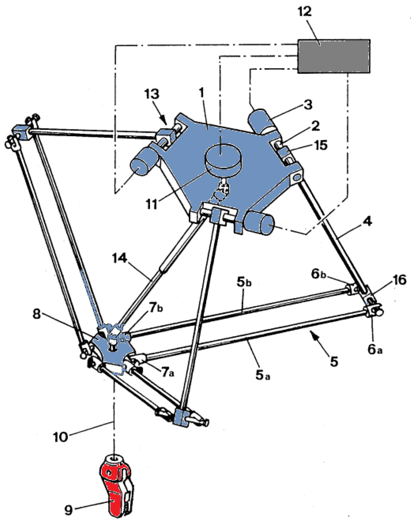
Figure 2.
3D model of the delta robot [5].
Figure 2.
3D model of the delta robot [5].
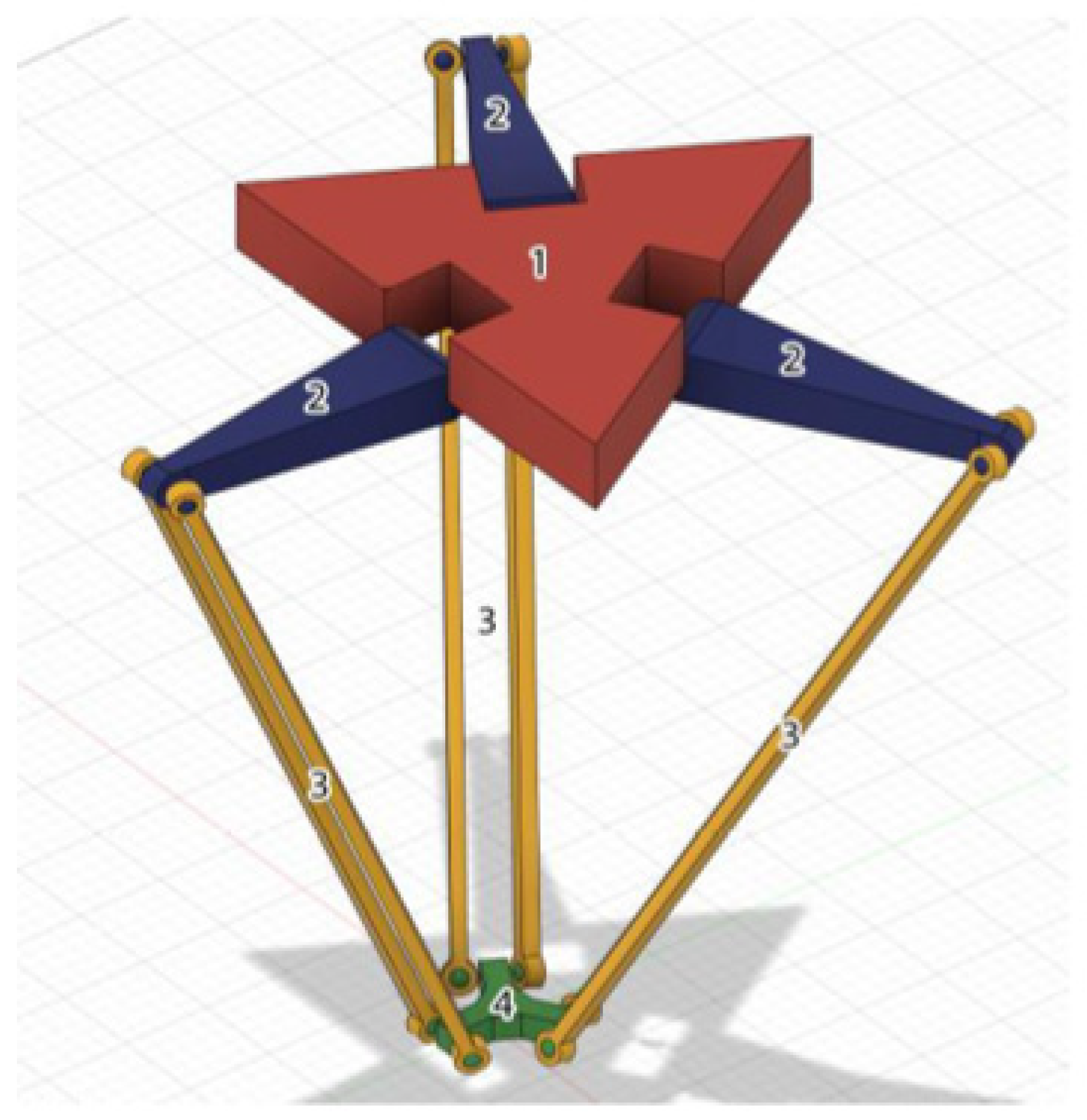
Figure 3.
Key parameters of the forward and inverse kinematic problem of the Delta Robot Manipulator.
Figure 3.
Key parameters of the forward and inverse kinematic problem of the Delta Robot Manipulator.
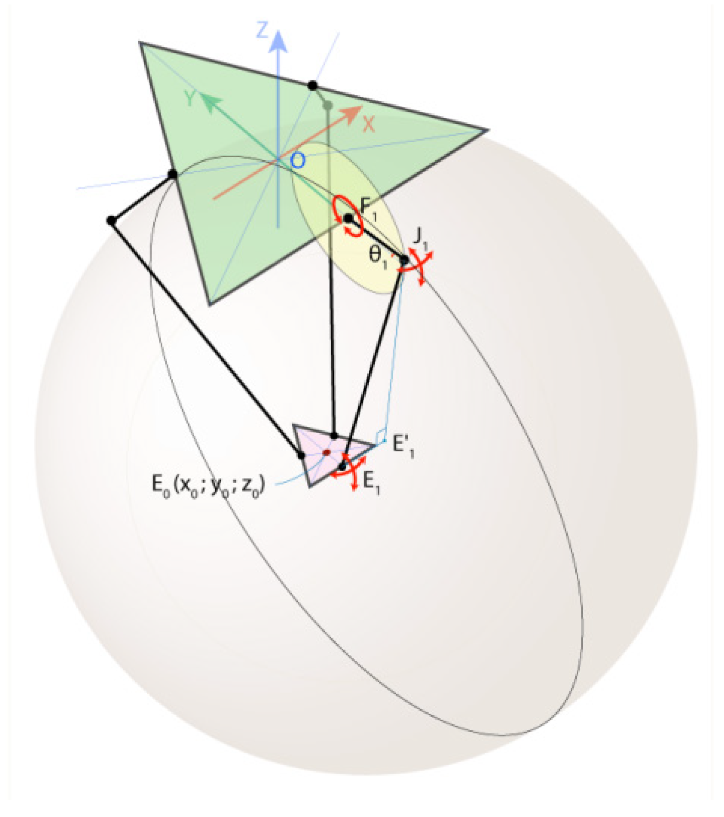
Figure 4.
3D model of the Delta robot (general view).
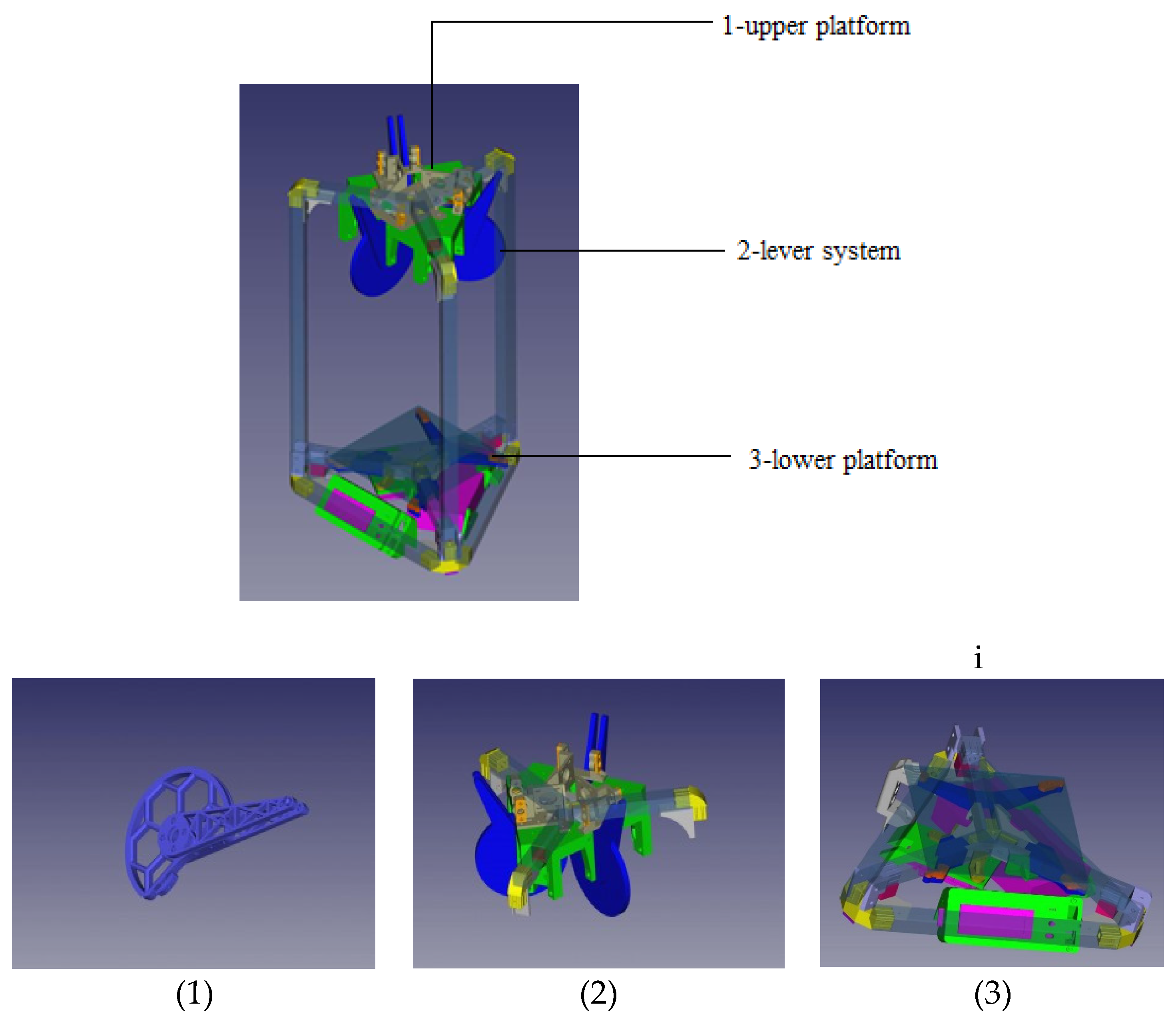
Figure 5.
Elements of the upper and lower platform. (a) “Upper carrier” element of the upper platform to support the gearbelt system. (b) “Carriage” element of the lower platform of the delta robot.
Figure 5.
Elements of the upper and lower platform. (a) “Upper carrier” element of the upper platform to support the gearbelt system. (b) “Carriage” element of the lower platform of the delta robot.
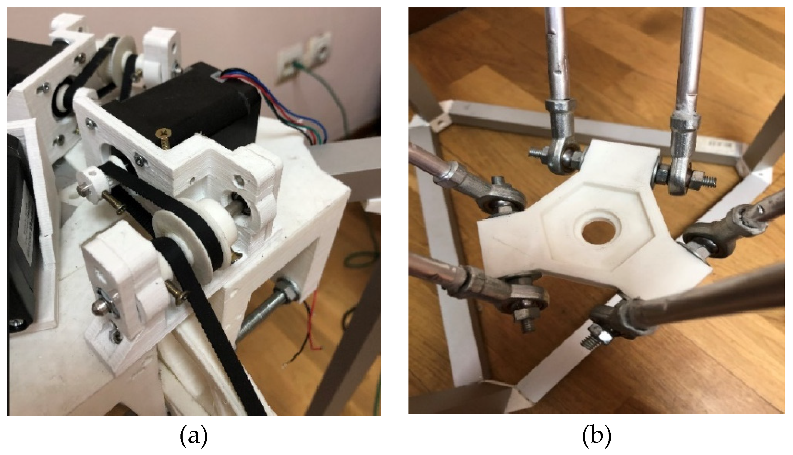
Figure 6.
Delta Robot Manipulator Top Platform. (a) “Top Holder” element of the upper platform with the gearbelt system. (b) General view from the top of the Upper Platform.
Figure 6.
Delta Robot Manipulator Top Platform. (a) “Top Holder” element of the upper platform with the gearbelt system. (b) General view from the top of the Upper Platform.
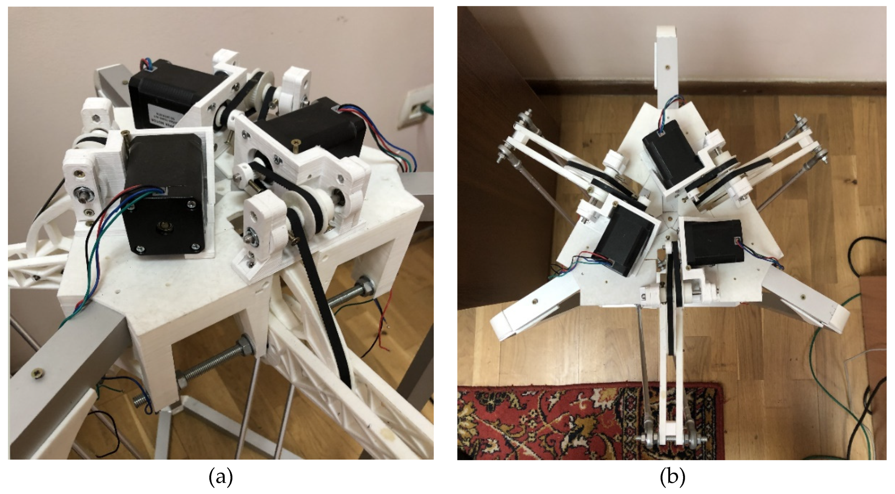
Figure 7.
Driver type DRV8825.
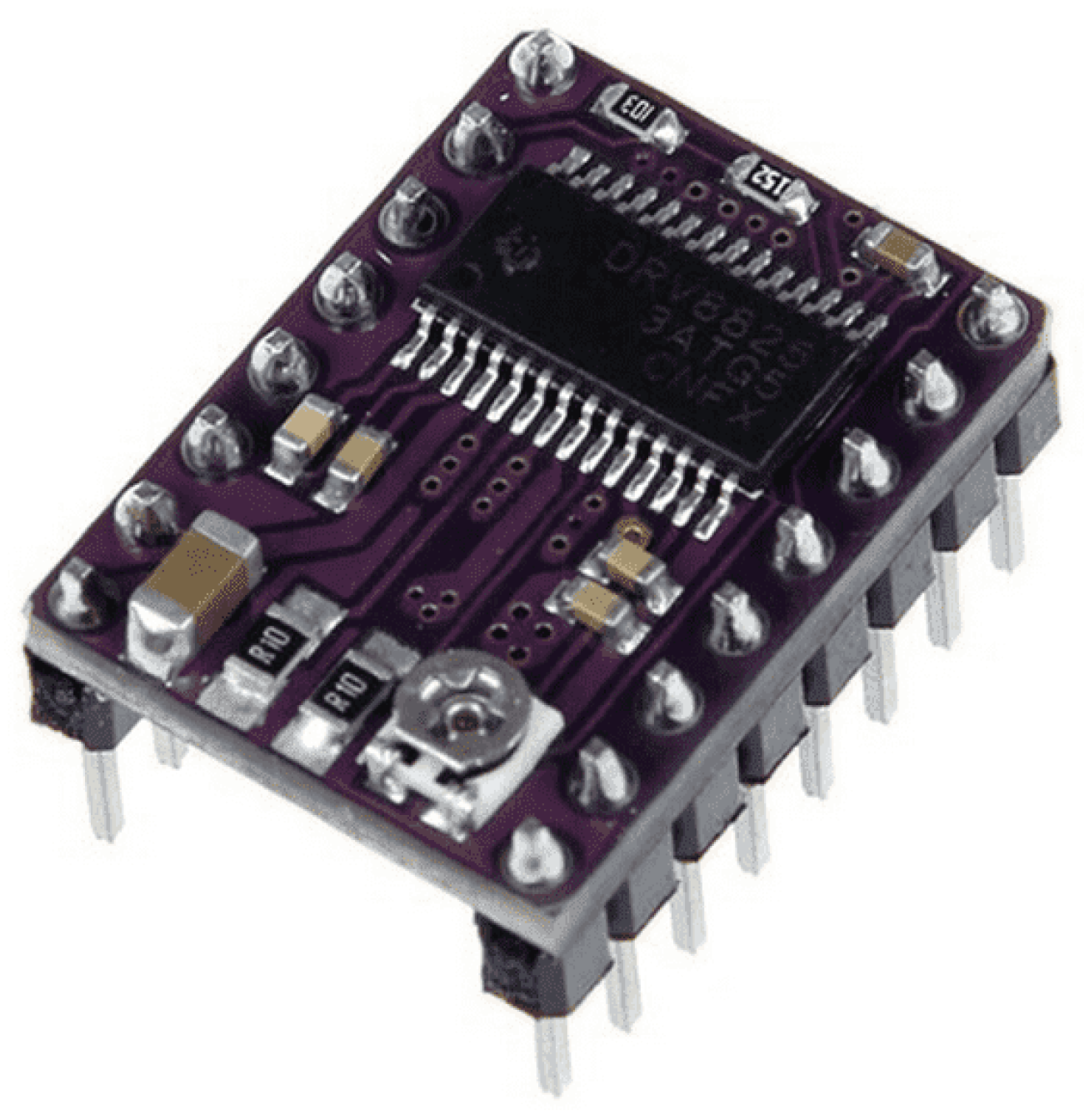
Figure 8.
Electronic wiring diagram of DRV8825 driver.
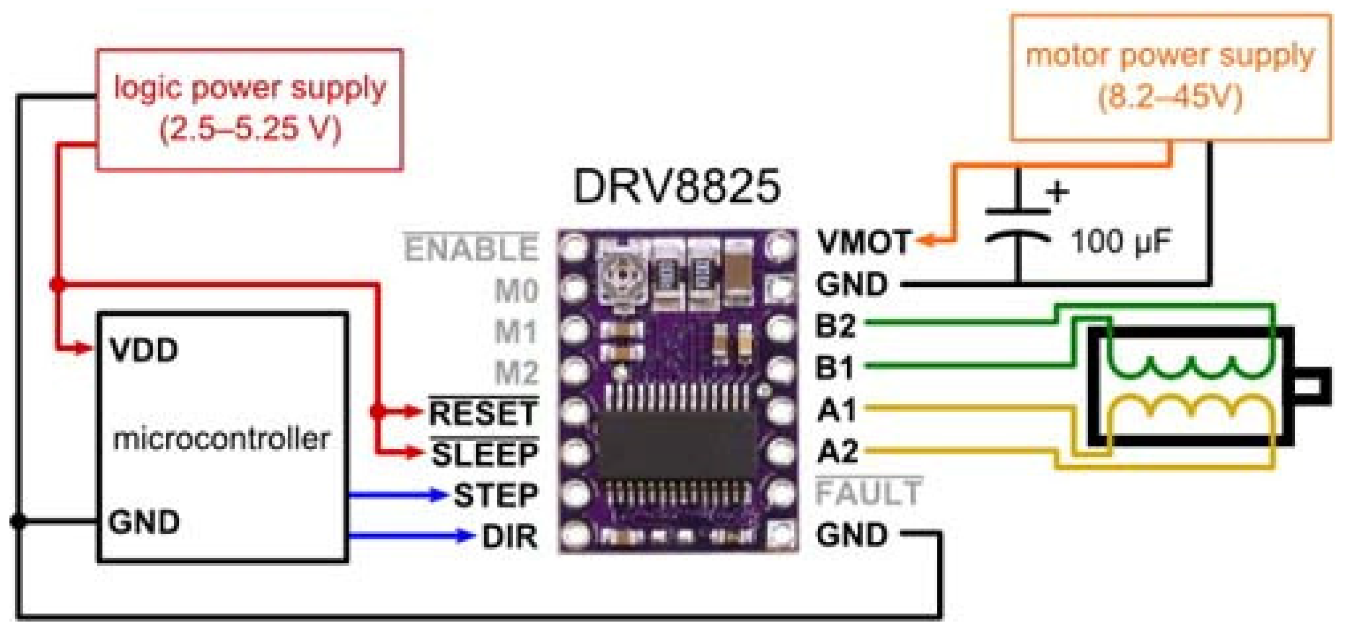
Figure 9.
Electronic wiring diagram of Delta Robot Manipulator components.
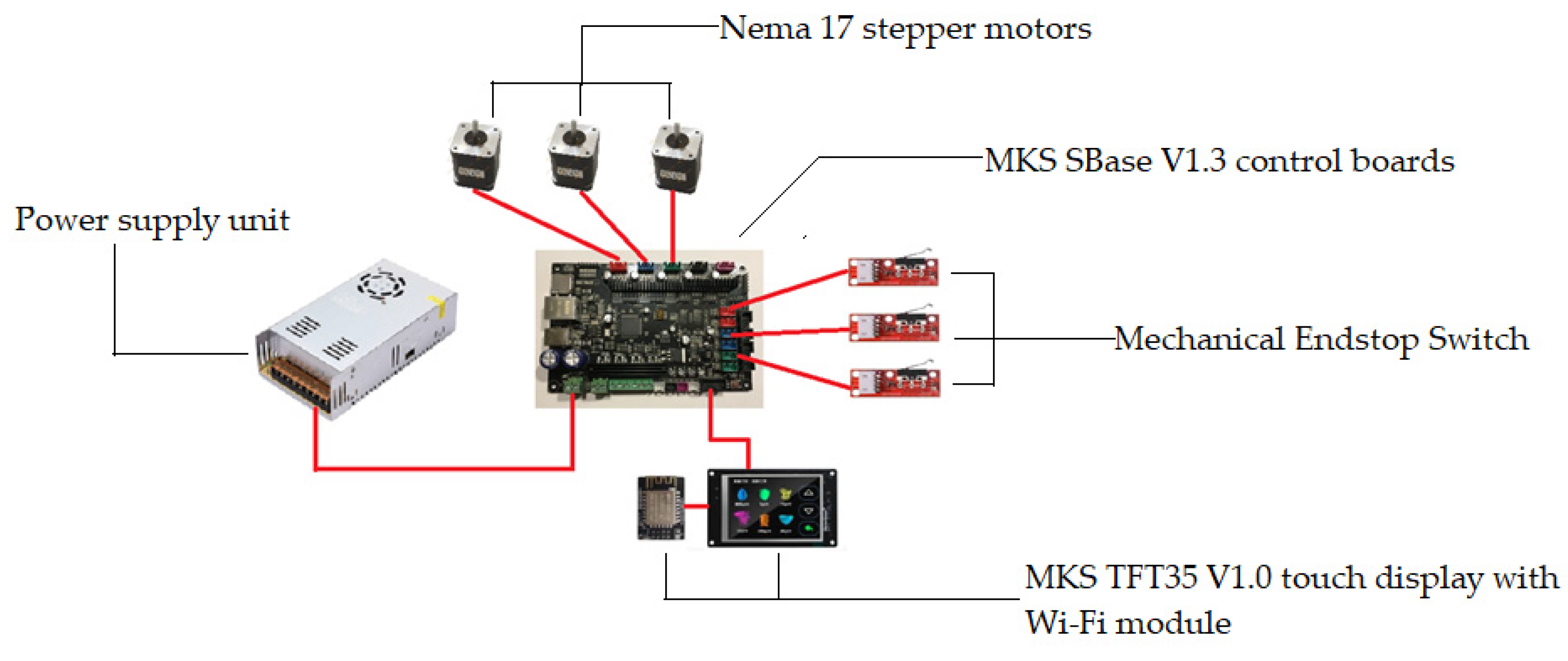
Figure 10.
Structure of convolutional neural network.
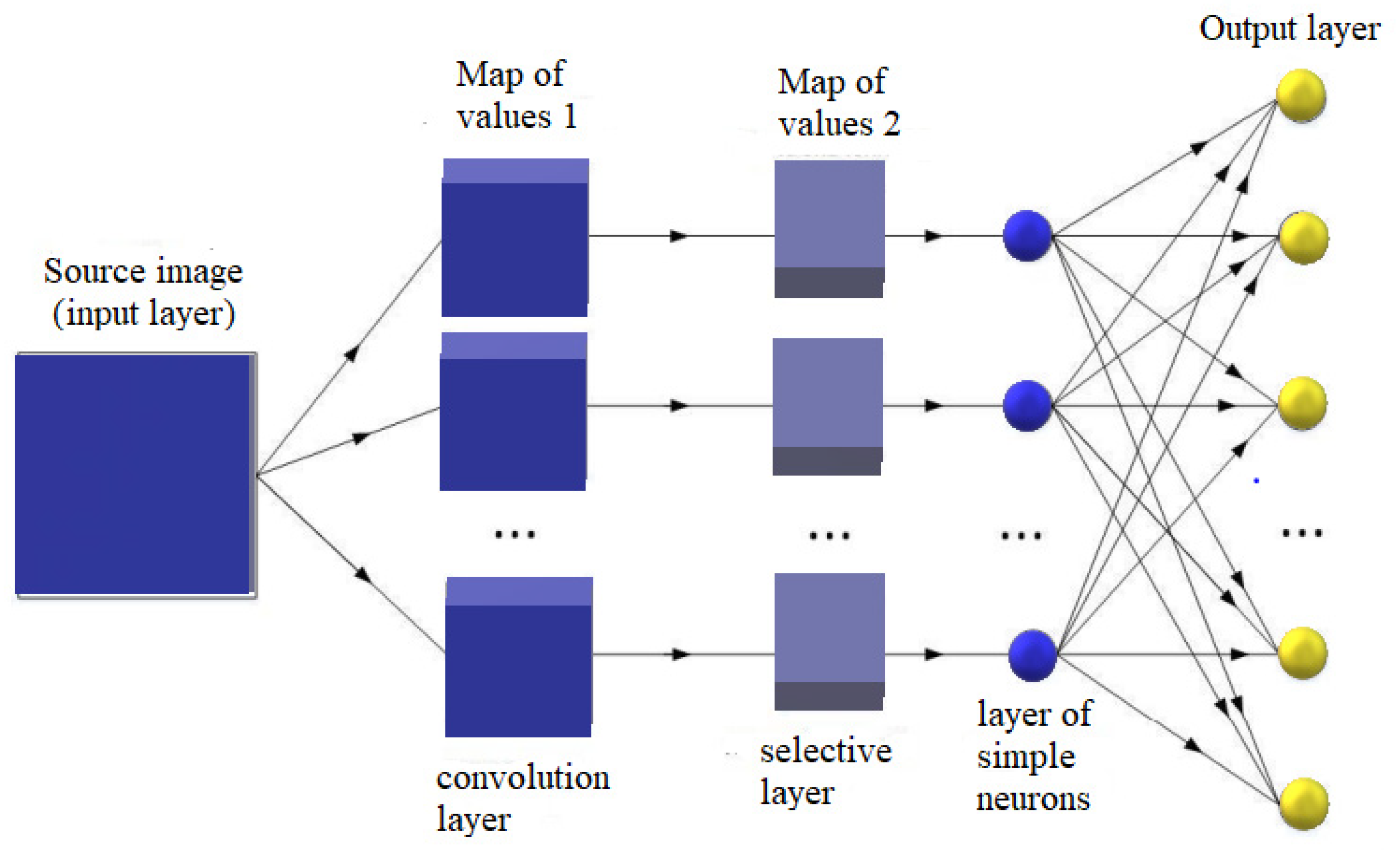
Figure 11.
Architecture of MASK-R-CNN algorithm with adaptive RGB model.
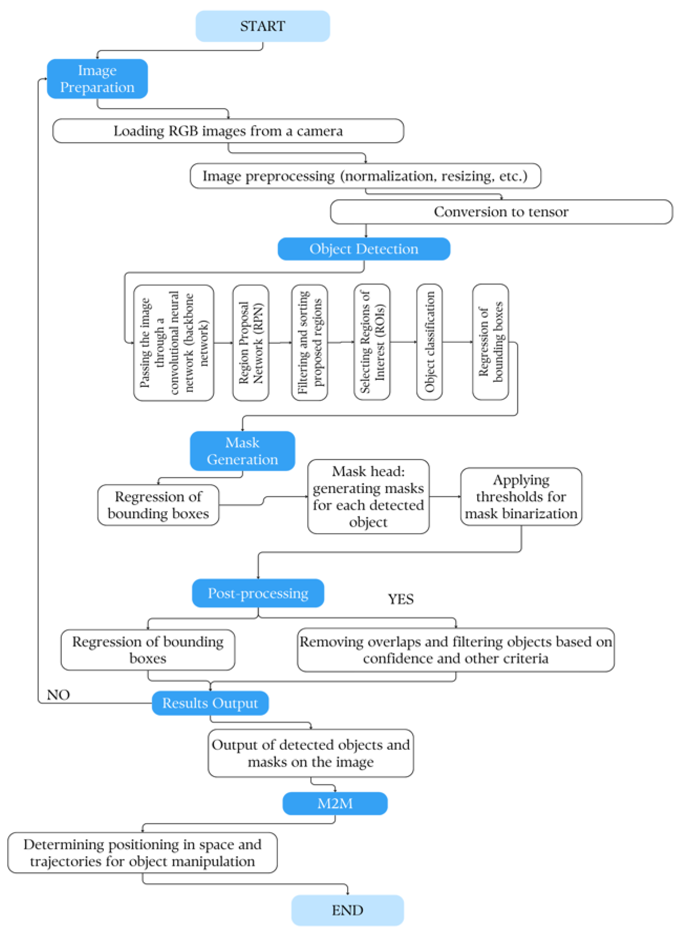
Figure 13.
The block diagram of the Delta manipulator.
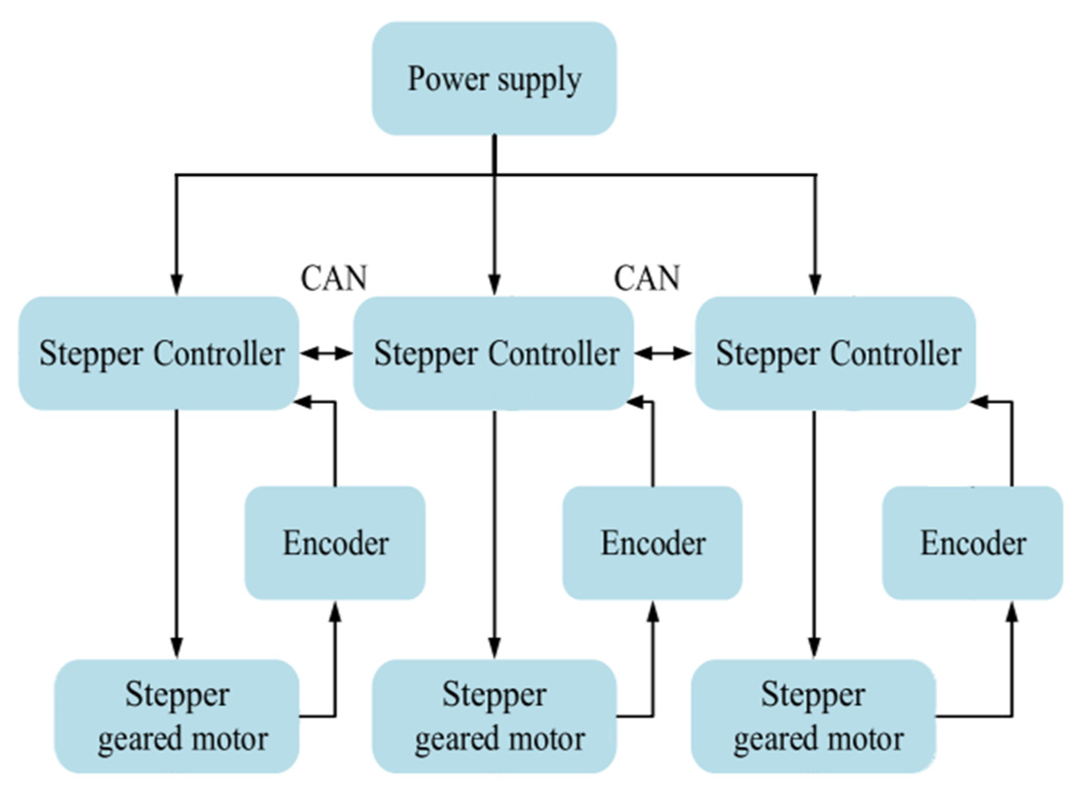
Figure 14.
The scheme of machine vision for identifying and tracking the trajectory of objects.
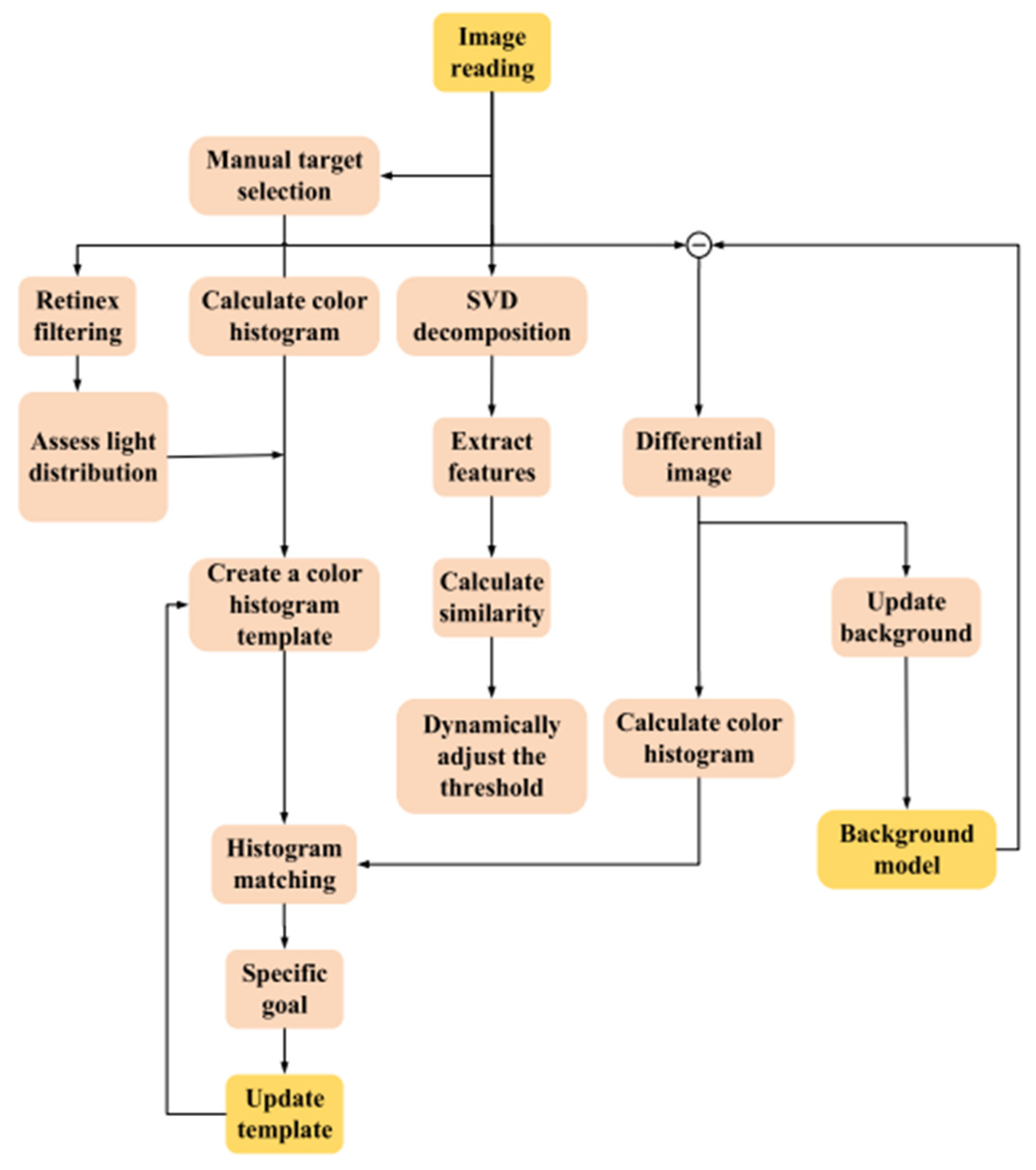
Figure 15.
Block diagram of machine-to-machine interaction (M2M) for artificial vision.
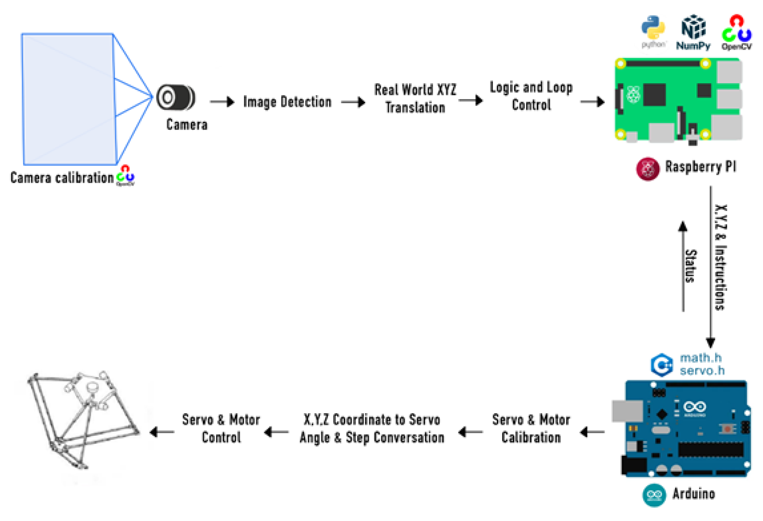
Figure 16.
The scheme of operation of the robotic platform for predicting the trajectory of movement.
Figure 16.
The scheme of operation of the robotic platform for predicting the trajectory of movement.
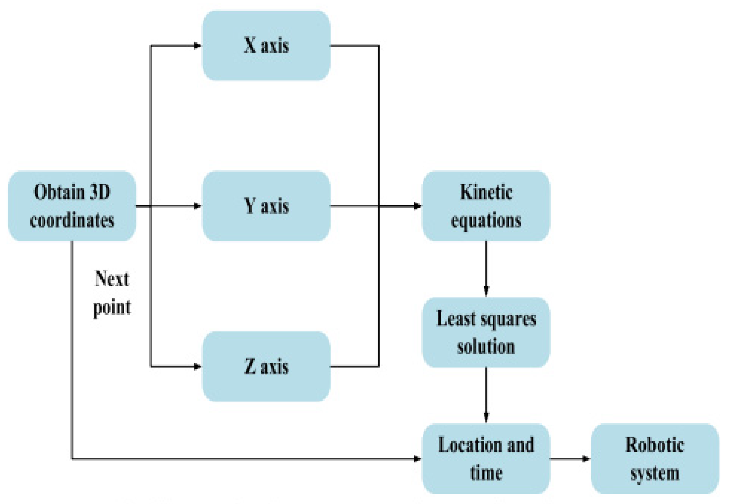
Figure 17.
The scheme of operation of the Delta manipulator control model.
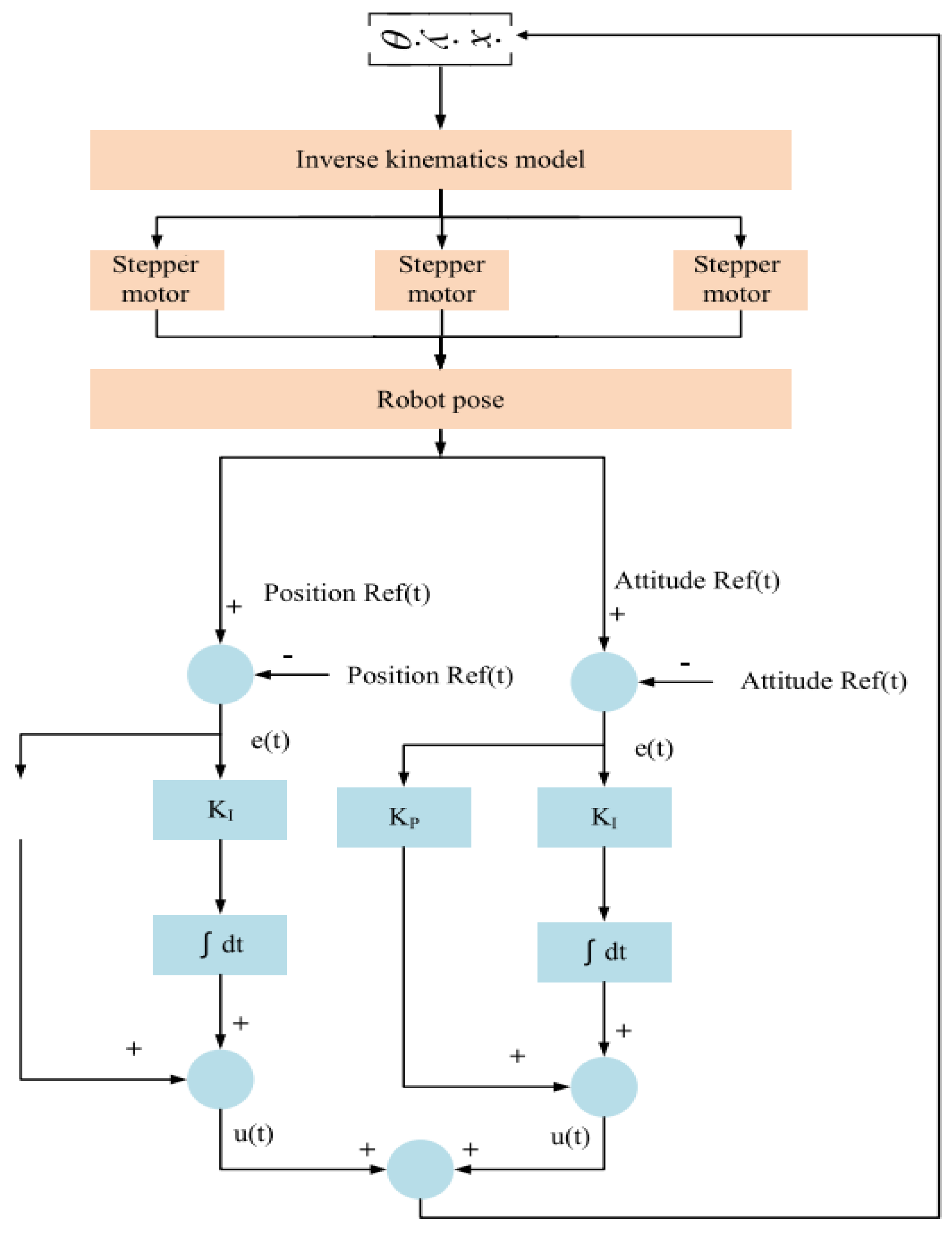
Figure 18.
The initial position of the delta robot manipulator.
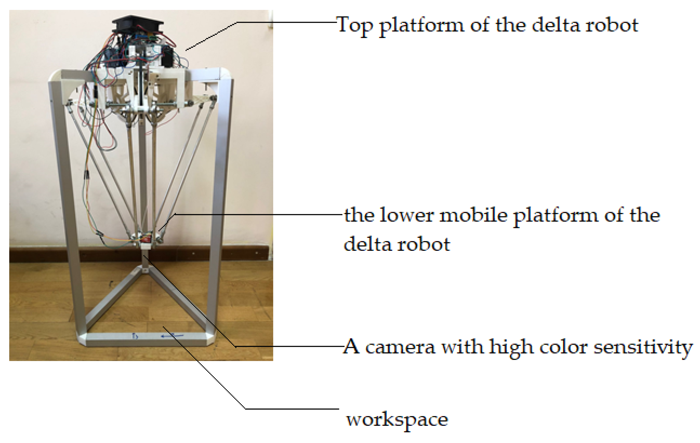
Figure 19.
Operating position of the delta robot arm. Initial position of the delta robot arm at startup b) Standby position after the initial coordinates of the lower base have been determined.
Figure 19.
Operating position of the delta robot arm. Initial position of the delta robot arm at startup b) Standby position after the initial coordinates of the lower base have been determined.

Figure 20.
Python software interface when realizing the process of determining the initial coordinates of the bottom base.
Figure 20.
Python software interface when realizing the process of determining the initial coordinates of the bottom base.
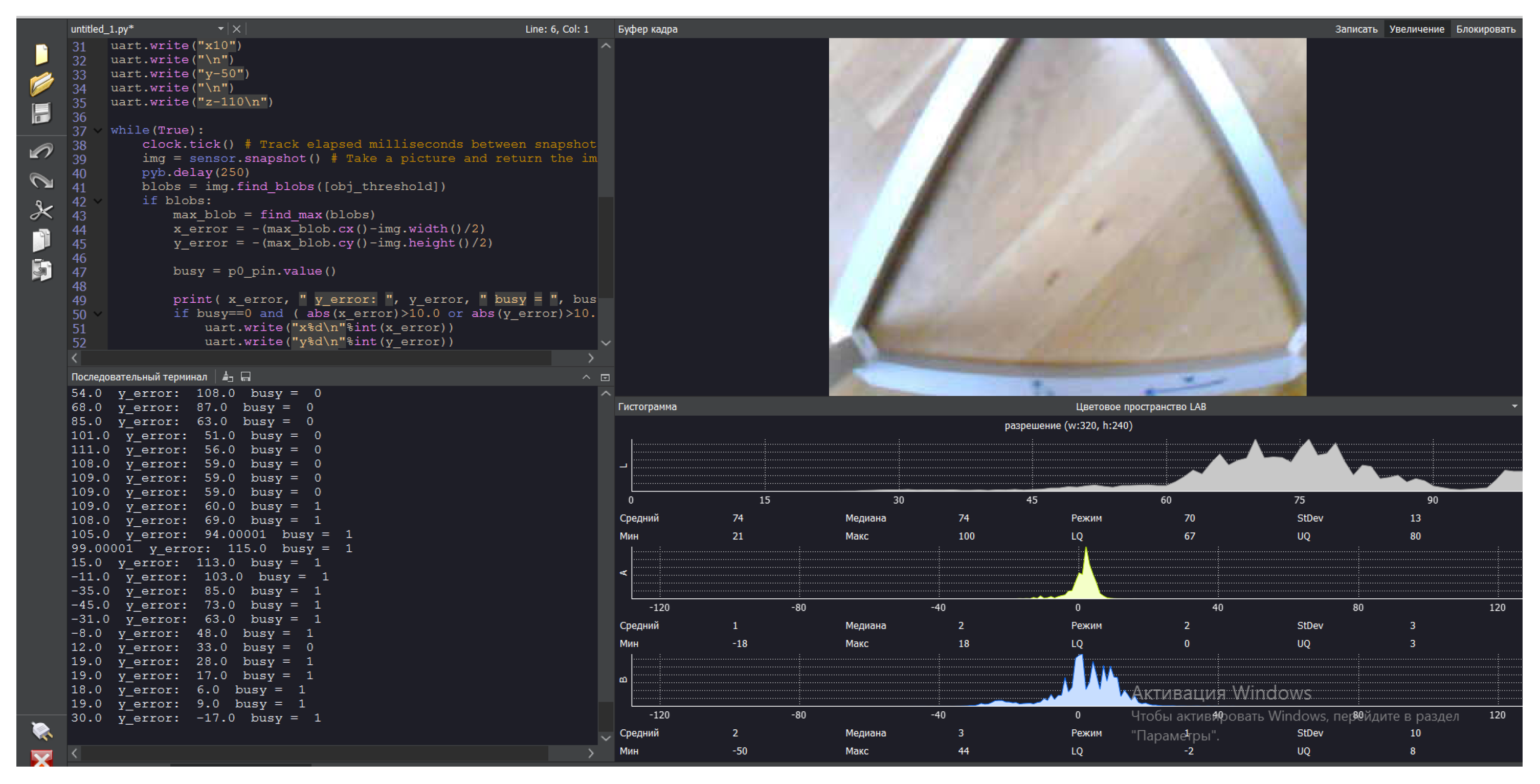
Figure 21.
Positioning of the delta robot arm depending on changes in the location of the sensing object. (a) The object under study is located in the center, and the manipulator position is adapted to the side of the object, towards the center. (b) When the object’s location changes to the right side, the manipulator position is shifted to the right side of the workspace. (c) When the object’s location changes to the left side, the manipulator position is shifted to the left side of the workspace.
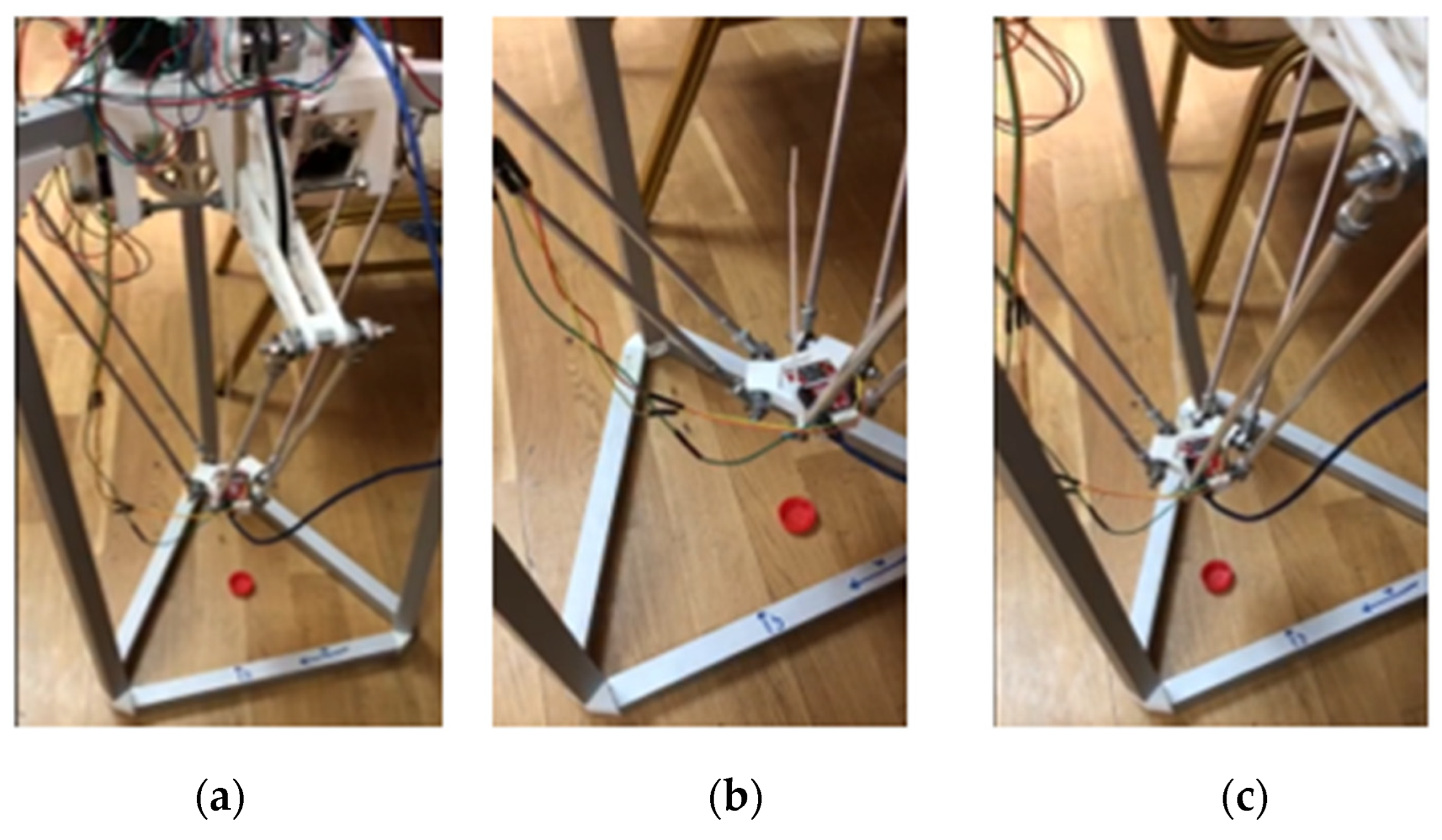
Figure 22.
Software interface of detection and centered focusing processes over an object with parameters color, shape - “Red, Circle” with application of YOLOv8 architecture.
Figure 22.
Software interface of detection and centered focusing processes over an object with parameters color, shape - “Red, Circle” with application of YOLOv8 architecture.
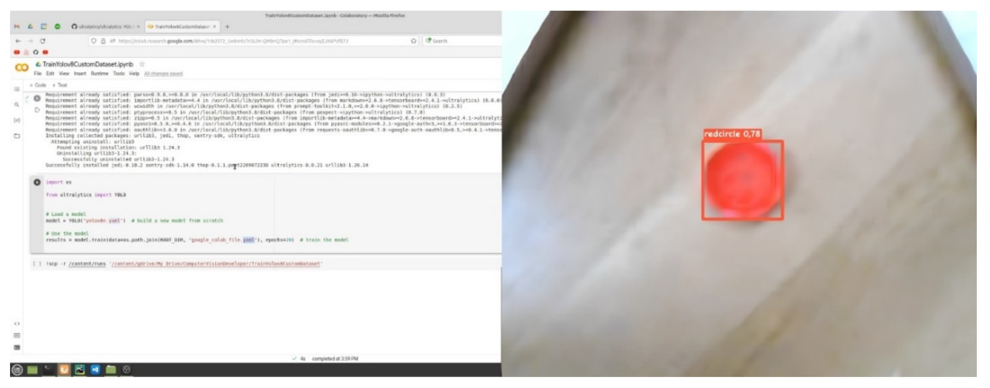
Figure 23.
Detection and centered focusing over an object with parameters color, shape - “Green, Square” using YOLOv8 architecture.
Figure 23.
Detection and centered focusing over an object with parameters color, shape - “Green, Square” using YOLOv8 architecture.
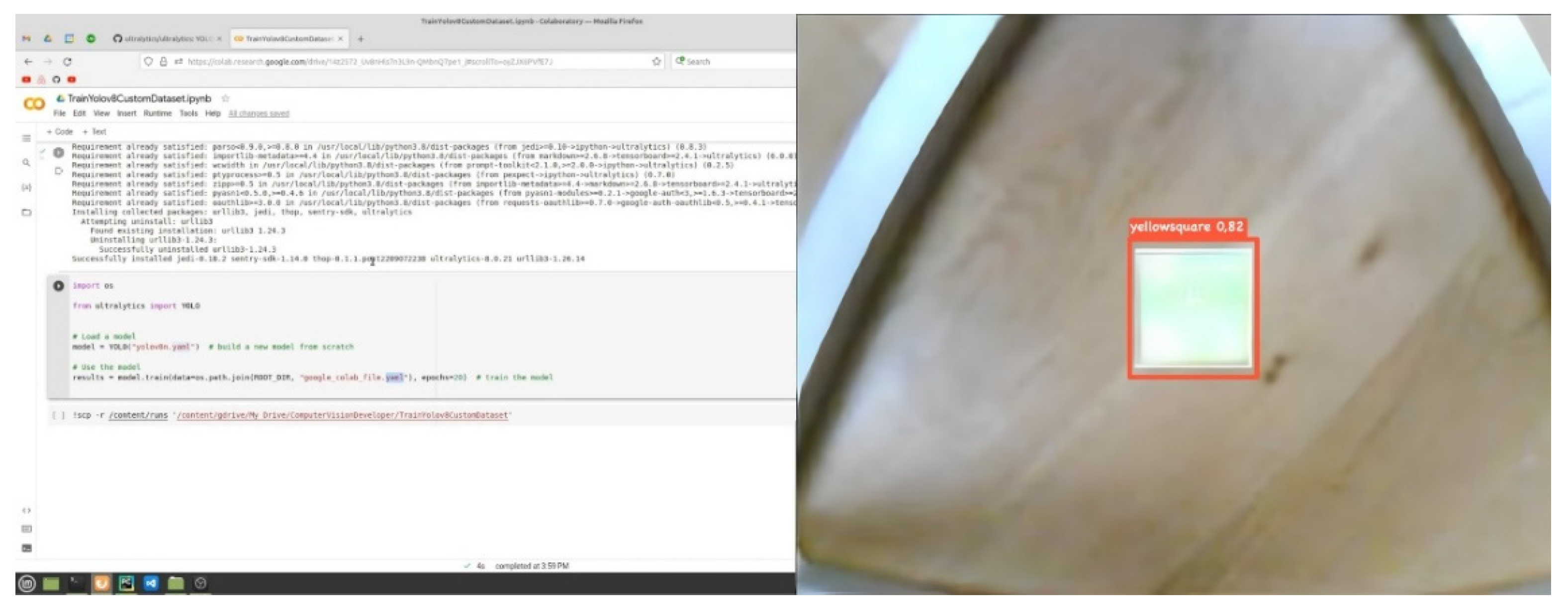
Figure 24.
The software interface of detection and centered focusing processes over the object with parameters color, shape - “Red, Circle” with the application of MASK-R-CNN algorithm architecture with adaptive RGB model.
Figure 24.
The software interface of detection and centered focusing processes over the object with parameters color, shape - “Red, Circle” with the application of MASK-R-CNN algorithm architecture with adaptive RGB model.
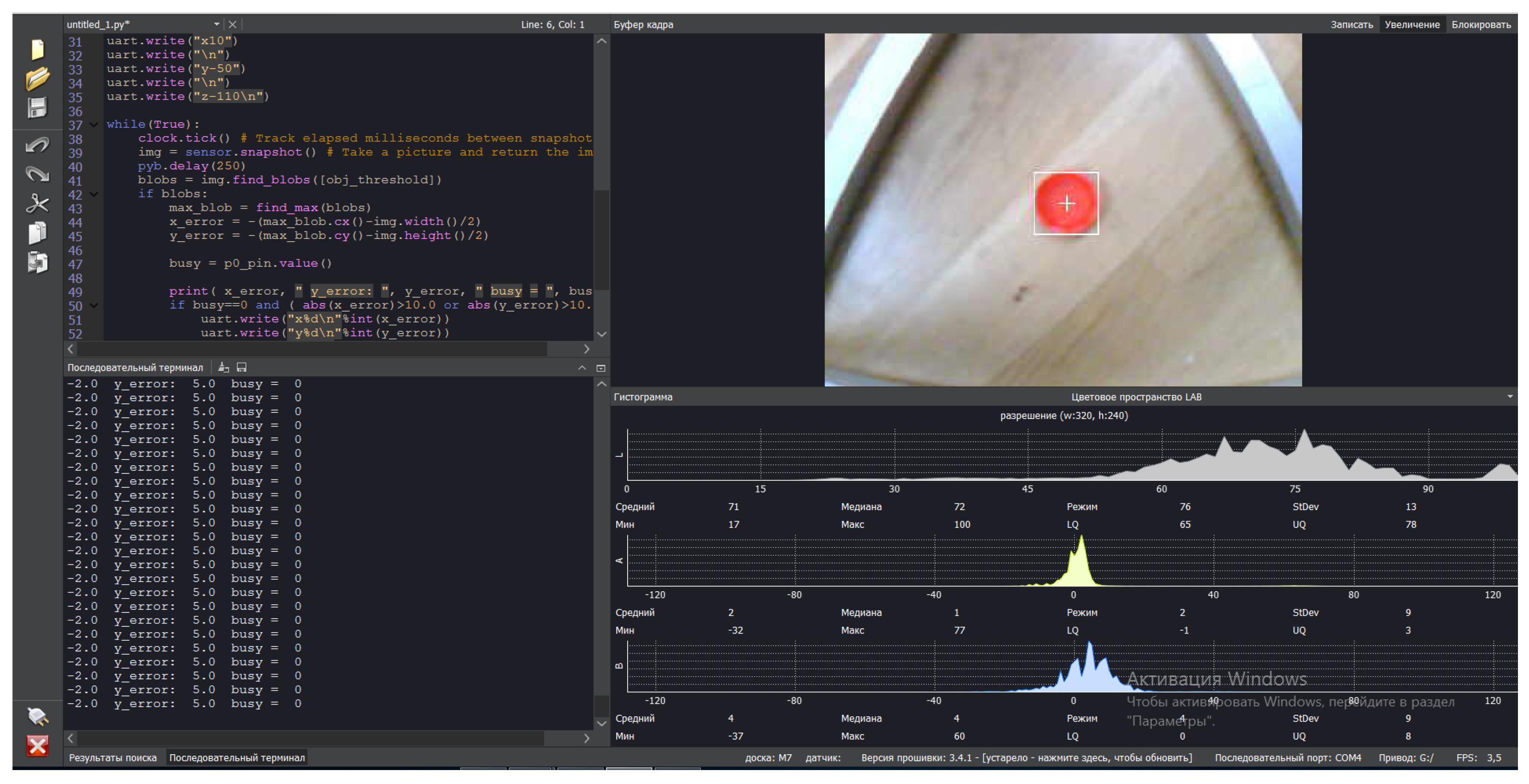
Figure 25.
Detection and centred focusing over an object with parameters colour, shape - “Green, Square” using MASK-R-CNN algorithm architecture with adaptive RGB model.
Figure 25.
Detection and centred focusing over an object with parameters colour, shape - “Green, Square” using MASK-R-CNN algorithm architecture with adaptive RGB model.
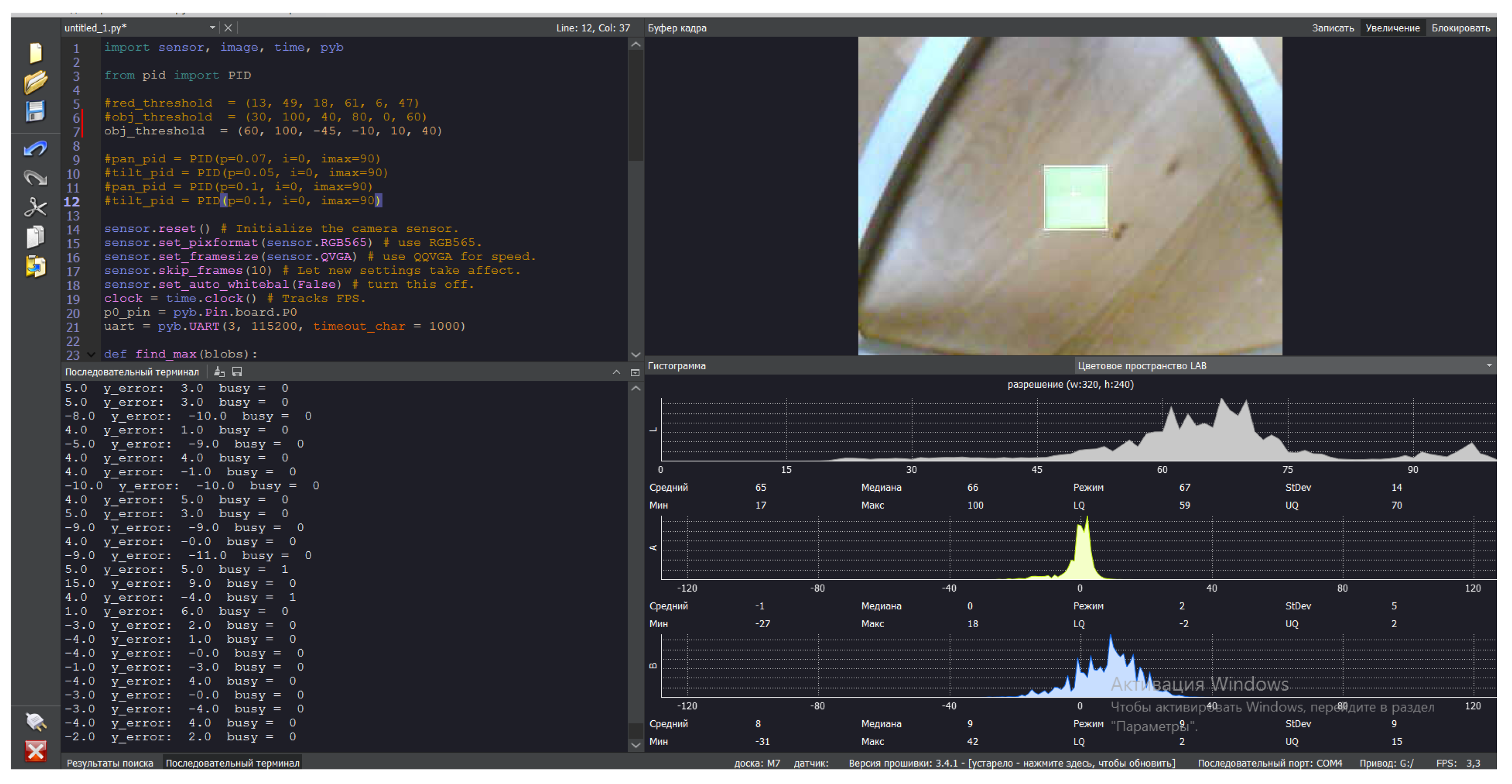

Table 1.
Comparison of MASK-R-CNN algorithm models.
| № | Model | Number of learning epochs | Recognition accuracy on the test sample | Object detection time, sec | ||
|---|---|---|---|---|---|---|
| Red, Circle | Green, Square | Red, Circle | Green, Square | |||
| 1 | YOLOv8 | 50 | 0,78 | 0,82 | 1,497 | 1,568 |
| 2 | RGB | 50 | 0,905 | 0,943 | 2,001 | 1,965 |
Disclaimer/Publisher’s Note: The statements, opinions and data contained in all publications are solely those of the individual author(s) and contributor(s) and not of MDPI and/or the editor(s). MDPI and/or the editor(s) disclaim responsibility for any injury to people or property resulting from any ideas, methods, instructions or products referred to in the content. |
© 2024 by the authors. Licensee MDPI, Basel, Switzerland. This article is an open access article distributed under the terms and conditions of the Creative Commons Attribution (CC BY) license (http://creativecommons.org/licenses/by/4.0/).
Copyright: This open access article is published under a Creative Commons CC BY 4.0 license, which permit the free download, distribution, and reuse, provided that the author and preprint are cited in any reuse.


