
Submitted:
20 April 2024
Posted:
23 April 2024
You are already at the latest version
Abstract
Abrasive Water Jet Machining (AWJM) is a non-conventional machining process that, unlike other methods, is deemed superior because of its applicability, versatility, and no heat-affected zones in the target material. The main objective of this paper was to develop a cheap, practical model for a low-pressure water jet cutting machine and provide some empirical test data for cutting delicate materials. Proper design calculations were performed and are included for both the water jet machine and the two-axis numerical control. Finite Element Analysis results validate the structural integrity of beams and columns in AWJM. Computational Fluid Dynamic analysis of the nozzle shows good agreement with the theoretical calculations regarding the pressure and velocity of the water-abrasive mixture exiting the nozzle. Modal analysis in ANSYS was done to mitigate potential failure due to resonance induced by vibrations. Limited testing on various thicknesses of polystyrene foam ranging from 1-5 mm thickness and rubber sheet of 1 mm thickness showed that even low pressure of 25-30 bar was sufficient to produce a kerf without any burr. However, extensive testing to report optimized parameters like nozzle transverse speed, standoff distance, abrasive flow rate, etc for working at low-pressure ranges is still a consideration for future investigation.
Keywords:
non-conventional machining
; computational fluid dynamic
I. Introduction
Abrasive water jet cutting is used to cut almost all types of materials like metals, polymers, ceramics, etc. Being a non-conventional process, it is expensive but highly preferred when the heat-affected zone is a significant concern. Humans have been manually cutting materials for approximately 5000 years. However, in the latter half of the 20th century, humans began to assemble and manufacture simple cutting gadgets. With time, the changes led to automated cutting, as is evident today. Initially, soft materials were cut, and with time this technology improved to cut more rigid materials such as solid metals. The first use of water jet cutting technology ever recorded was in the cutting of ceramic materials, which were to be used as an insulating matter for space shuttles of Boeing [1]. Today majority of non-conventional methods are used for cutting, but one of the most advanced mechanical processes is abrasive water jet cutting. Substances that chemically react with water are some of the exceptions for the AWJM [2].
The process of abrasive water jet cutting causes the erosion of materials through the forceful impact of a high-velocity water jet combined with abrasive particles [3]. The AWJM cutting process stands as a potent technology for machining diverse engineering materials across a wide spectrum of thicknesses. Its application spans various materials reflecting its broad utilization in modern manufacturing contexts [4,5,6]. The absence of a heat-affected zone, its non-contact nature between the tool and workpiece, and the low machining force exerted on the work surface, have propelled the adoption of this method over alternative machining processes [7,8]. In a study examining the influence of machining parameters on the surface topography and roughness of titanium metal using AWJM, significant insights were gleaned regarding the factors affecting surface roughness. Particularly, it was noted that the standoff distance exhibited a proportional relationship with the average surface roughness [9]. In another study jet pressure and standoff distance effect on the surface roughness of brass 360 was observed. Their findings revealed that water jet pressure emerged as the most influential factor associated with surface roughness [10]. The Taguchi method stands out as the most suitable approach for identifying optimized parameters while minimizing the number of experiments required, all without compromising quality [11,12]. Employing the Taguchi experimental method, an analysis was conducted to investigate the average surface roughness in AWJM cutting of cast iron metal. Parameters such as transverse speed, water pressure, standoff distance, and material feed rate were identified as influential factors affecting surface roughness. Notably, water pressure emerged as the most crucial factor, exhibiting an inversely proportional relationship with average surface roughness [13]. A study was conducted to examine the impact of AWJM process parameters, including water pressure, nozzle traverse speed, abrasive mass flow rate, and standoff distance, on the surface roughness (Ra) of aluminum. The results revealed that employing high water pressure and maintaining a low standoff distance is preferable for achieving a desirable surface finish [14]. A Taguchi method-based Analysis of Variance (ANOVA) was proposed to optimize the Abrasive Water Jet Machining process parameters to reduce average surface roughness. The significance of process parameters was assessed through variance analysis utilizing the L9 orthogonal array. The investigation unveiled that the feed rate emerged as the most crucial parameter influencing surface roughness [15].
Today the abrasive water jet cutting machines commercially available are being operated at pressures of 400 MPa or above to cut more rigid and tougher materials. The process is commonly used on an industrial scale. There are limited studies for abrasive water jet cutting machines that are available to operate at low pressures, e.g., less than 100 bar. Also, there exist minimal studies regarding the machining of more delicate materials at low pressure. As the operating pressure of commercially available AWJM is manyfold times the required pressure to cut the softer materials, this leads to increased power consumption, making it unviable for cutting delicate materials. This study focuses on the manufacturing of AWJM that operates at low pressures, making it cost-effective. Moreover, it also serves as a test-bed for studies on abrasive water jet cutting at low pressures. The maximum operating pressure for our AWJM is a gauge pressure of 32 bar.
II. Design Considerations
Before designing any component, a complete schematic diagram was developed. A general arrangement of the features in this regard can be seen in Figure 1.
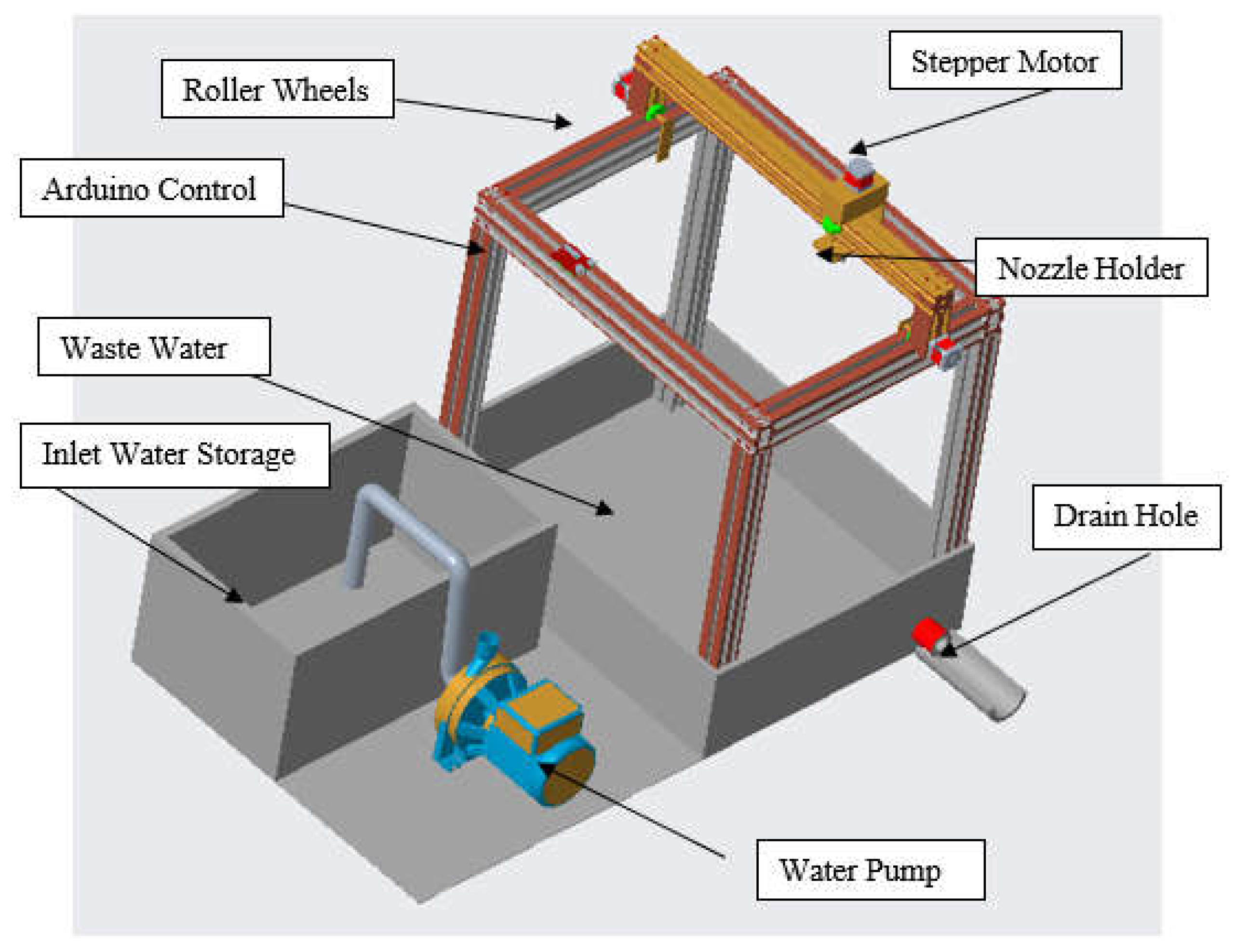
This general schematic diagram of the abrasive water jet cutting machine was then modeled in CAD software (Creo Parametric), and upon fabrication, it was expected to be like Figure 2.
The details of the selection/design of the components are given in chronological order below.
Pump
We selected a positive displacement pump. They are useful for flow rates below 100 m3/min and higher pressures. Since our flow rate was below this approximate threshold, and the pressure value was high (32 bar), a positive displacement pump was an ideal choice. For fluids like water, both positive displacement and centrifugal pumps are good options; however, positive displacement pumps have a higher efficiency than centrifugal pumps. The pump was motor-driven, and the intensifier attached to the pump generated and retained the high pressure required for cutting. Besides this, the 4-horsepower induction motor was used in this setup because it was a reliable and cost-effective option. The 3-phase motor used had higher efficiency and a good power factor.
Figure 2.
Model of AWJM designed in Creo Parametric Software.
Upper Cutting Head
The cutting head is a term collectively used for piping and nozzle along with the mixing chamber of abrasive particles. Generally, nozzles are made up of material like stainless steel. Some of the materials used in the industry for the manufacturing of nozzles are sapphire, ruby, and diamond, with a diameter range of 0.08 to 0.8 mm. However, these materials are very costly and, by no means, justify the cost of cutting soft materials.
High-pressure flexible pipes carry pressurized water to the nozzle. The nozzle converts the pressure head into the velocity head. Abrasives are mixed with the water before the water passes through the nozzle exit orifice.
Nozzle
The design of the nozzle was based on several factors ranging from velocity limitation, manufacturing constraint, and the cost of manufacturing. The nozzle orifice hole was kept at 0.5 mm because it was practically impossible to make a hole smaller due to our limited resources.
Abrasives were added through a separate chamber in the nozzle. The nozzle diameter selection also determined the size of the abrasive particles. Using very fine particles of a nanometer could be very costly and difficult to procure, choosing particles of a few micrometers was a viable option. The ANSYS analysis of the proposed nozzle with the flow of water with abrasive is shown in Figure 3.
The maximum pressure at the nozzle exit is 4.8×10⁷ Nm-2. The diameter at the outlet of the nozzle was 0.5 mm, so the exit area is . The upward thrust produced by the nozzle is:
This maximum thrust will be used later to calculate the forces on the beam and column for making a better and more effective design for the CNC structure.
Water Jet Exit Velocity
The velocity of the water that exits through the outlet is given by .
The Re for flow in a pipe is
The relationship between the velocity of the water-abrasive mixture exiting the nozzle and pressure is shown to increase monotonically up till the pressure limit of our setup was reached. This can be seen in Figure 4.
Flow rate of the Water-Abrasive Mixture through the Exit
The flow rate can be calculated using the below equation. Cd = 0.6 was used in our setup.
Relationship between the flow rate of the water-abrasive mixture and the pressure can be seen in Figure 5. The flow rate increases initially rapidly but with more increase in pressure the flow rate shows a declining trend which is expected due to possible backflow at the exit.
Power of Abrasive Water Jet
The relationship between the power of the water jet and pressure can be seen to be exponentially increasing as shown in Figure 6.
Abrasives
There is a wide variety of abrasives that are used in abrasive water jet cutting machining like the commonly found silica sand, aluminium oxide, olivine (sometimes used), etc. Silicon Carbide, due to its greater hardness, makes the largest width of cut. The abrasive we used was a mixture of the above compounds with a concentration of about 20% SiC to avoid clogging the nozzle. The mass of the abrasive was controlled, and a fixed amount of abrasive was added to prevent choking. The power of abrasive is simply calculated by formulation, shown below. The average density of flow changes when water mixes with abrasive. Note that the calculation is based on pressure in bar and diameter in mm.
The average density of the flow mixture has been calculated by the equation [16].
Mass of Abrasive
The mass of the abrasive can be determined using the formula:
The relation between the mass flow of abrasive and pressure can be seen in Figure 7. Increasing the pressure pushes more abrasives initially, but further pressure increases start choking the nozzle exit due to the small nozzle outlet.
Power of Abrasive
To determine the power of the abrasive for cutting we used the equations below:
The power of abrasives also shows an exponential increase by increasing the pressure which can be seen in Figure 8. Adding more finer abrasives will have a high impact on the cutting ability of the jet.
Flexible Piping
To get cost-effective and high-pressure pipes from the market, high-pressure flexible hose-annular, T321 pipes were selected. The nominal diameter available was ¾ inch. With complete data available for its pressure rating and maximum temperature range along with its weight per foot, it seemed like the best available option [17].
CNC Numerical Control Design
Design and Analysis of Structure
The design consideration for the CNC structure heavily relied upon the fact that the structure should be strong enough to resist any type of failure. The nozzle was allowed to move in 2D. There were two different modes of failure that the structural member could undergo. Firstly, the nozzle force could deflect and damage the beams and columns. Secondly, the columns were fixed, introducing an additional moment. Incorporating the force and moment helped in determining the maximum force needed to be resisted by the structure to prevent buckling or yielding.
Design and Analysis of Upper Beam
Due to the strength requirement, stainless steel was selected. The precision needed for the fineness of the cut would not be affected if the standoff distance decreased by 0.00128 mm for our setup. This deviation in standoff caused the accuracy of kerf width to be affected by less than 1% of the data available in the literature [16]. This deviation occurs due to the thrust force exerted by the water. The maximum deflection would occur when the nozzle reaches the center of the beam. Considering the weight of the beam along with the water jet force, the maximum available force was calculated. The top view projection of the CNC frame can be seen in Figure 9.
By applying the maximum deflection of the beam fixed at both ends in the formula, the desired moment of inertia of the beam was calculated. Fixing the standoff distance to 2 mm, the maximum deflection occurring in the beam was theoretically 0.0128 mm; hence the kerf width was affected by less than 1%, which was within the 0.1 mm accuracy target.
The value of ‘I’ comes out to be:
Design and Analysis of Supporting Column
The beams could undergo buckling if the desired forces exceeded the considered values. The complete data of the forces was calculated (nozzle water jet force and beam weight). Translating these forces to the side structure additionally introduced a moment too. Now, this force value was chosen, such that it corresponded to the maximum amount of force that the system experienced. The amount of the axial force over each column was calculated based on them. Another assumption was that the force was exerted axially over the column with no eccentricity. The forces and the moments on the CNC frame can be seen in Figure 10.
The length of the column was defined beforehand based on our space constraint. Hence, the Euler formula was used to calculate the critical moment of inertia. However, in this case, the simple length was not chosen because the column was fixed at both ends. We used the effective length denoted by K, which is K = 0.5 since the column was fixed at both ends. Translating 27 N force on the beam:
Modal Analysis of Setup
To avoid resonance, modal analysis was also performed; its results were compared and counted into the calculations of base structure and design. These vibrations, if left unattended, could cause material failure. If the induced vibrations of the motor and plunger pump matched with the natural frequency of the whole structure model, resonance could have occurred, which would not only cause inaccuracies in the cutting process but also highly compromise the integrity of the entire setup. The modal analysis performed gave different modes of vibration where resonance could occur. Upon comparison, it turned out that none of the modes matched anywhere near our actual produced vibrations, which was a significant proof of our designed setup to be safe from resonances.
Selection of Stepper Motor
The selection of a motor in the case of a numerically driven machine was the most integral part because it had to provide the required torque needed to drive the whole upper beam in a very subtle way. Of all the available motors, the stepper motor option seemed to be the best because it could provide the required acceleration and velocity. With a step accuracy of 0.01 mm, it can be used without fear of affecting the cut precision. The power of the motors depended on the torque required, and this involved incorporating many different forces like rotational inertial forces and rotational acceleration forces. The total mass of the beam, motors, and the nozzle was:
- Mass of the beam + Mass of the Upper Frame + Mass of the Nozzle = 1.1 kg
- Mass of 3 Motors = 0.6 kg
- The total mass of all components = 1.7 kg
The total forces comprise of two parts, mass and thrust force:
Total Force = Mass Force + Thrust Force = 27 N
The rolling resistance calculated is shown in Table 1.
For calculating the maximum linear acceleration we defined minimum and maximum velocity as 7 mm/s and 0 mm/s. Hence the total acceleration each second could be 7 mm/s2
The total linear accelerating forces are shown in Table 2.
Total forces are obtained by adding rolling resistance and accelerating forces:
Total Force = 0.27 N + 0.0189 N = 0.2889 N
Torque = r = 0.2889×0.02 = 0.00578 Nm
This is linear torque. Now the rotational inertia is calculated from the equation below:
The total inertia of the individual elements is:
| Load (kg.m2) | Pulley (kg.m2) | Belt (kg.m2) | Total (kg.m2) |
| 0.00108 | 0.000004 | 0.000012 | 0.001096 |
Rotational speed can be seen in Table 3.
The power required is calculated by:
III. Results and Discussion
The complete water jet assembly and the CNC structure for controlling the nozzle were manufactured and joined by a clamp for testing. The initial experiments for the thickness of polystyrene foam ranging from 1-5 mm thickness and rubber sheet of 1 mm thickness proved that low pressure of 25-30 bar was sufficient to produce a kerf without any burrs. The time of cutting was less than other conventional methods, and above all, no human interference was required. Although many avenues remained untouched in the experimentation phase like variation of different parameters like transverse speed, angle of orientation of nozzle, the variation of pressure, etc., however, preliminary testing showed that water jet cutting produced equally excellent and promising results even at low pressures. The manufactured model was cheap, useful, and completely automated. The water jet machine was designed based on the desired accuracy while producing a kerf with tight tolerance limits. The automation was done in such a way that the kerf fineness would never be disturbed. The components that were finally manufactured were done with a factor of safety of 1.5. The selection/design of components was based on preliminary theoretical calculations and was verified through the software available. FEA results validated the structural integrity of beams and columns in AWJM. CFD analysis of the nozzle showed good agreement with the theoretical calculations regarding the pressure and velocity of the jet exiting the nozzle. The modal analysis was done to avoid failure due to resonance caused by the vibrations. However, extensive testing remains an integral part of our future study.
Funding
This research did not receive any grants.
Acknowledgment
We thank all the anonymous reviewers for their hard reviewing work.
References
- Brozek, M. (2017). Steel cutting using abrasive water jet. In Proceedings of the International Scientific Conference, Jelgava, Latvia.
- M. Hashish and Water Jet Technology Association., Proceedings of the 7th American Water Jet Conference, August 28- 31, 1993, Seattle, Washington. Water Jet Technology Association, 1993.
- Yuvaraj, N.; Pradeep Kumar, M. Multiresponse Optimization of Abrasive Water Jet Cutting Process Parameters Using TOPSIS Approach. Mater. Manuf. Process. 2015, 30, 882–889. [Google Scholar] [CrossRef]
- Singh, S., Gupta, V., & Sankar, M. R. (2020). Abrasive Water Jet Machining. Advances in Abrasive Based Machining and Finishing Processes, 71-96.
- Tripathi, D.R.; Vachhani, K.H.; Kumari, S.; Dinbandhu; Abhishek, K. Experimental investigation on material removal rate during abrasive water jet machining of GFRP composites. Mater. Today: Proc. 2020, 26, 1389–1392. [Google Scholar] [CrossRef]
- Bhandarkar, V.; Singh, V.; Gupta, T. Experimental analysis and characterization of abrasive water jet machining of Inconel 718. Mater. Today: Proc. 2020, 23, 647–650. [Google Scholar] [CrossRef]
- Mohamad, W.; Kasim, M.; Norazlina, M.; Hafiz, M.; Izamshah, R.; Mohamed, S. Effect of standoff distance on the kerf characteristic during abrasive water jet machining. Results Eng. 2020, 6, 100101. [Google Scholar] [CrossRef]
- Bagchi, A.; Srivastava, M.; Tripathi, R.; Chattopadhyaya, S. Effect of different parameters on surface roughness and material removal rate in abrasive water jet cutting of Nimonic C263. Mater. Today: Proc. 2020, 27, 2239–2242. [Google Scholar] [CrossRef]
- Vasanth, S.; Muthuramalingam, T.; Vinothkumar, P.; Geethapriyan, T.; Murali, G. Performance Analysis of Process Parameters on Machining Titanium (Ti-6Al-4V) Alloy Using Abrasive Water Jet Machining Process. Procedia CIRP 2016, 46, 139–142. [Google Scholar] [CrossRef]
- Babu, M.N.; Muthukrishnan, N. Investigation on Surface Roughness in Abrasive Water-Jet Machining by the Response Surface Method. Mater. Manuf. Process. 2014, 29, 1422–1428. [Google Scholar] [CrossRef]
- Kumar, R.S.; Gajendran, S.; Kesavan, R. Estimation of Optimal Process Parameters for Abrasive Water Jet Machining Of Marble Using Multi Response Techniques. Mater. Today: Proc. 2018, 5, 11208–11218. [Google Scholar] [CrossRef]
- Badgujar, P.P.; Rathi, M.G. Taguchi method implementation in abrasive water jet machining process optimization. Int. J. Eng. Adv. Technol. 2014, 3, 66–70. [Google Scholar]
- Aultrin, K.J.; Anand, M.D. Optimization of machining parameters in AWJM process for an copper iron alloy using RSM and regression analysis. Int. J. Emerg. Eng. Res. Technol. 2014, 2, 19–34. [Google Scholar]
- Shibin, R.; Anandakrishnan, V.; Sathish, S.; Sujana, V.M. Investigation on the abrasive water jet machinability of AA2014 using SiC as abrasive. Mater. Today: Proc. 2020, 21, 519–522. [Google Scholar] [CrossRef]
- Selvan, M.C.P.; Raju, N.M.S.; Sachidananda, H.K. Effects of process parameters on surface roughness in abrasive waterjet cutting of aluminium. Front. Mech. Eng. 2012, 7, 439–444. [Google Scholar] [CrossRef]
- Jiang, S., Xia, Y., Popescu, R., Mihai, C., & Tan, K. (2005, August). Cutting capability equation of abrasive suspension jet. In Proceedings of 2005 WJTA American Waterjet Conference.
- High pressure flexible hose - annular. High Pressure Flexible Hose, Max Working Pressure 3250 psi. (n.d.). https://www.flexible-hose.org/flexible-metal-hose/high-pressure-flexible-hose.
Figure 1.
Schematic design of AWJM unit .
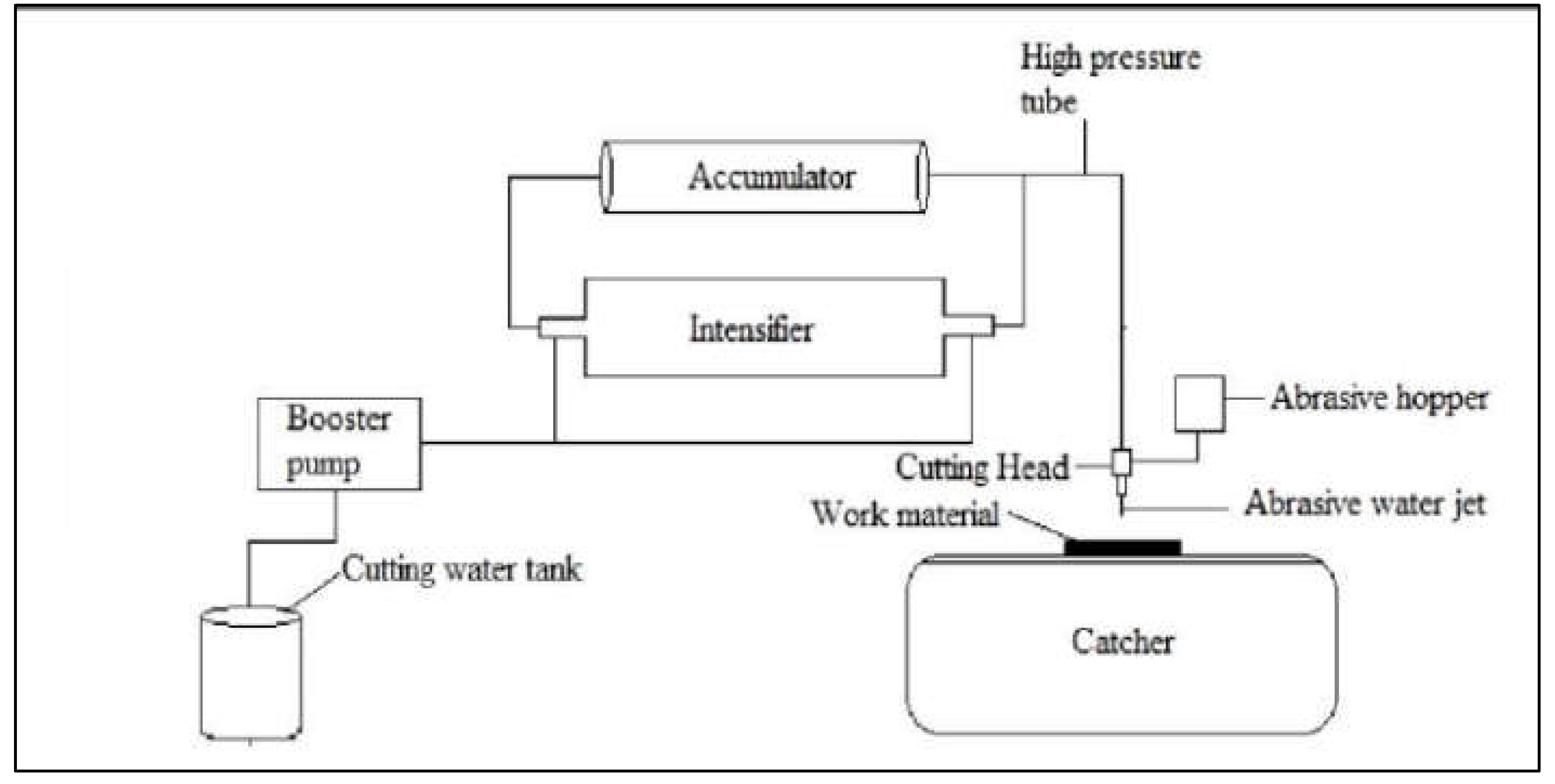
Figure 3.
Nozzle pressure analysis with maximum pressure observed at the exit.
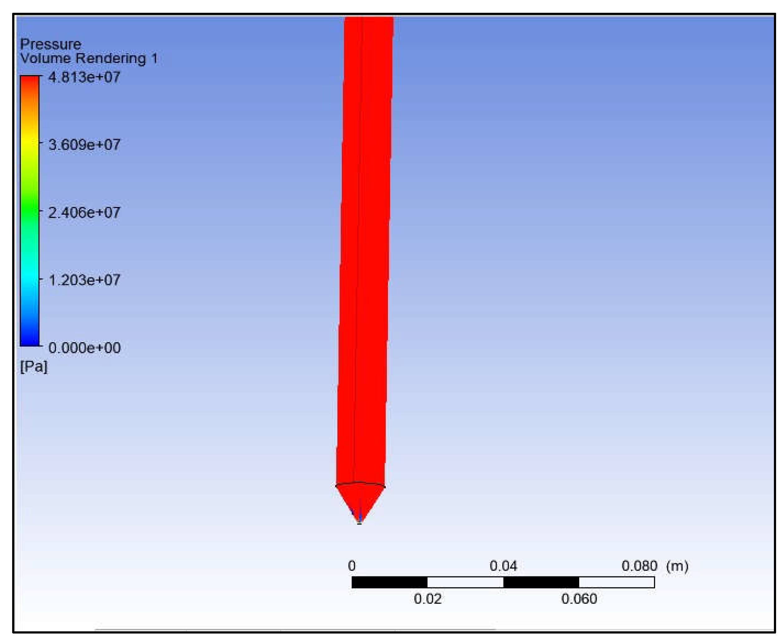
Figure 4.
Velocity of water-abrasive at exit versus variation with pressure.
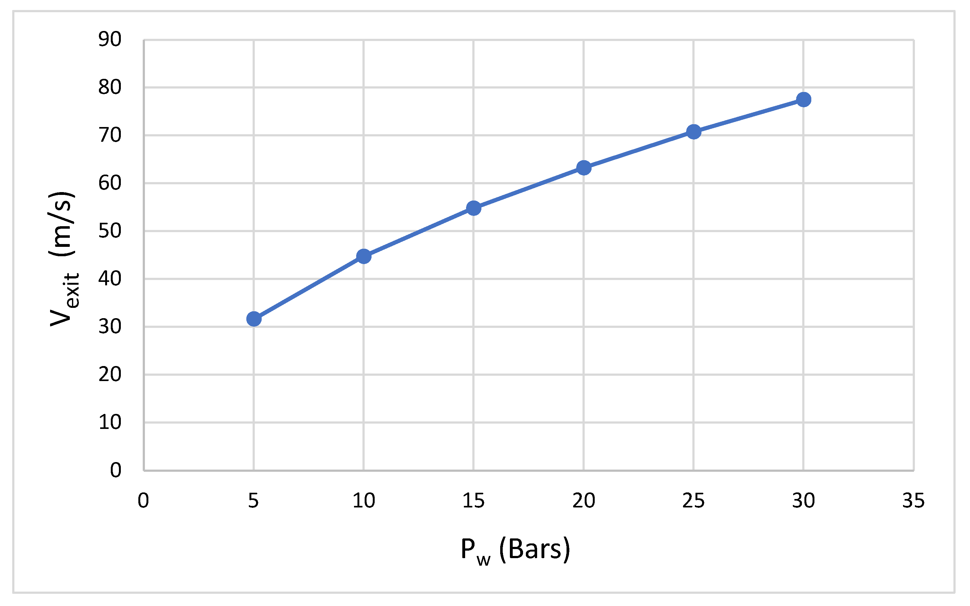
Figure 5.
Variation of flow rate through nozzle exit with pressure variation.
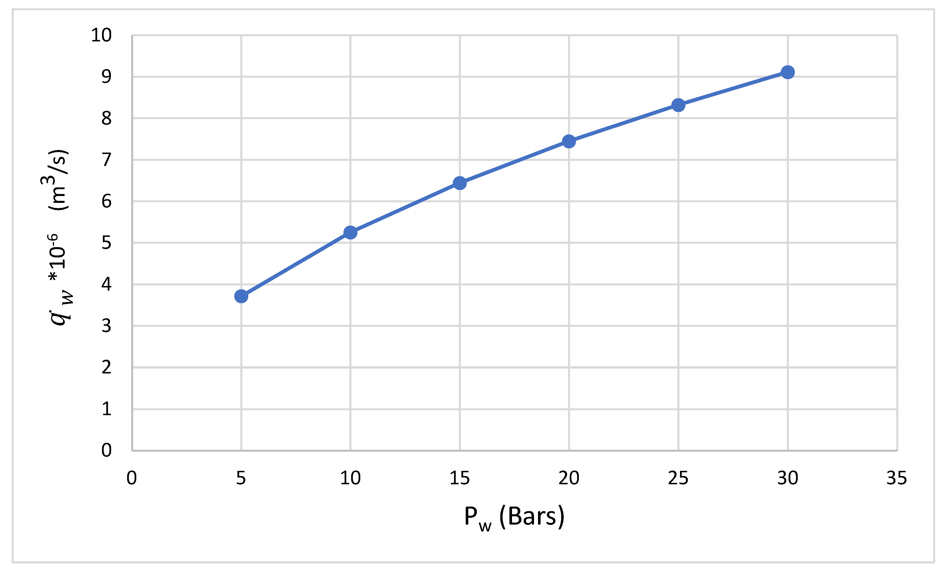
Figure 6.
Power of a water-abrasive mixture increases exponentially with increasing pressure.
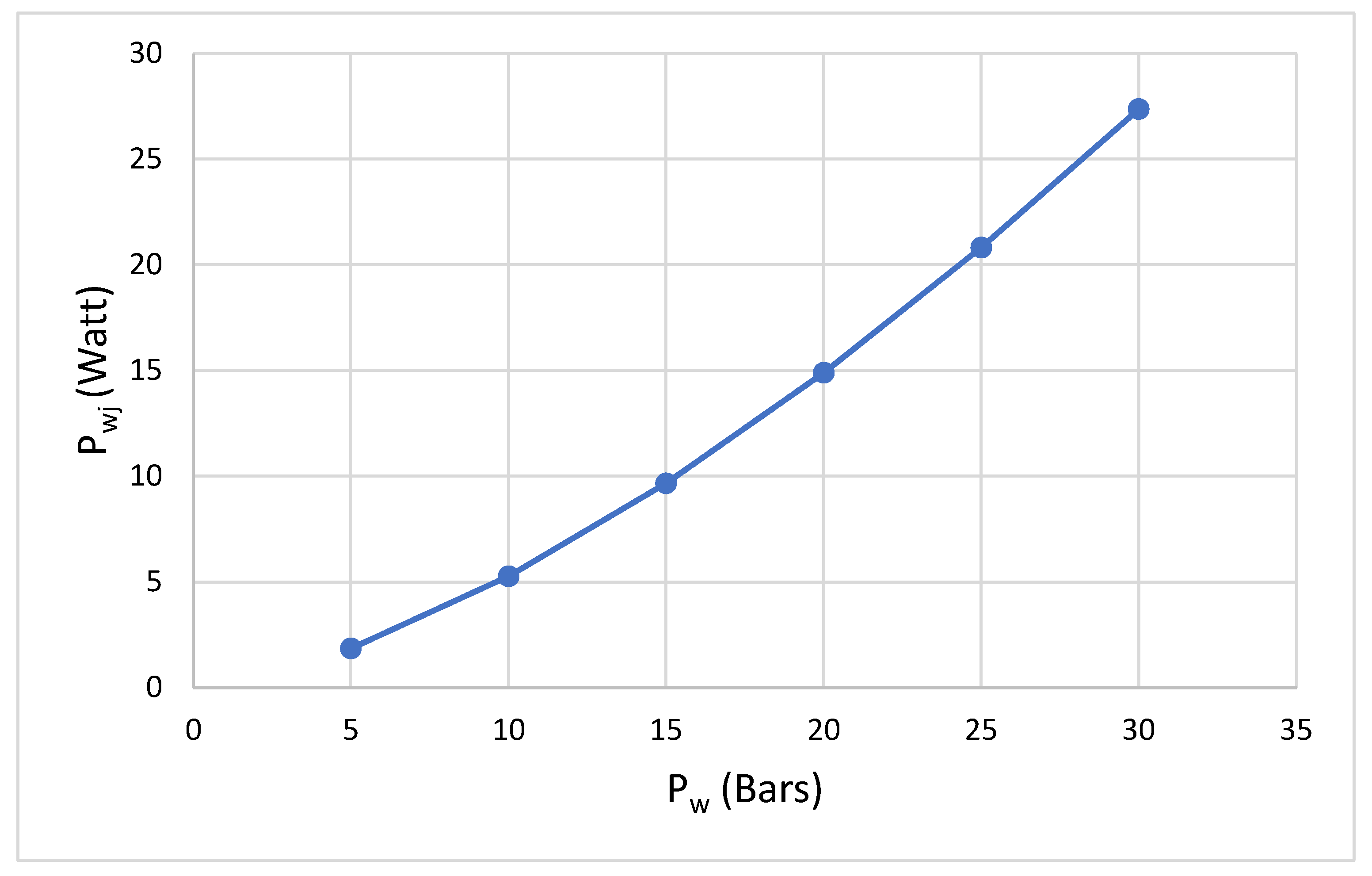
Figure 7.
Pressure effect on the mass flow rate of abrasive.
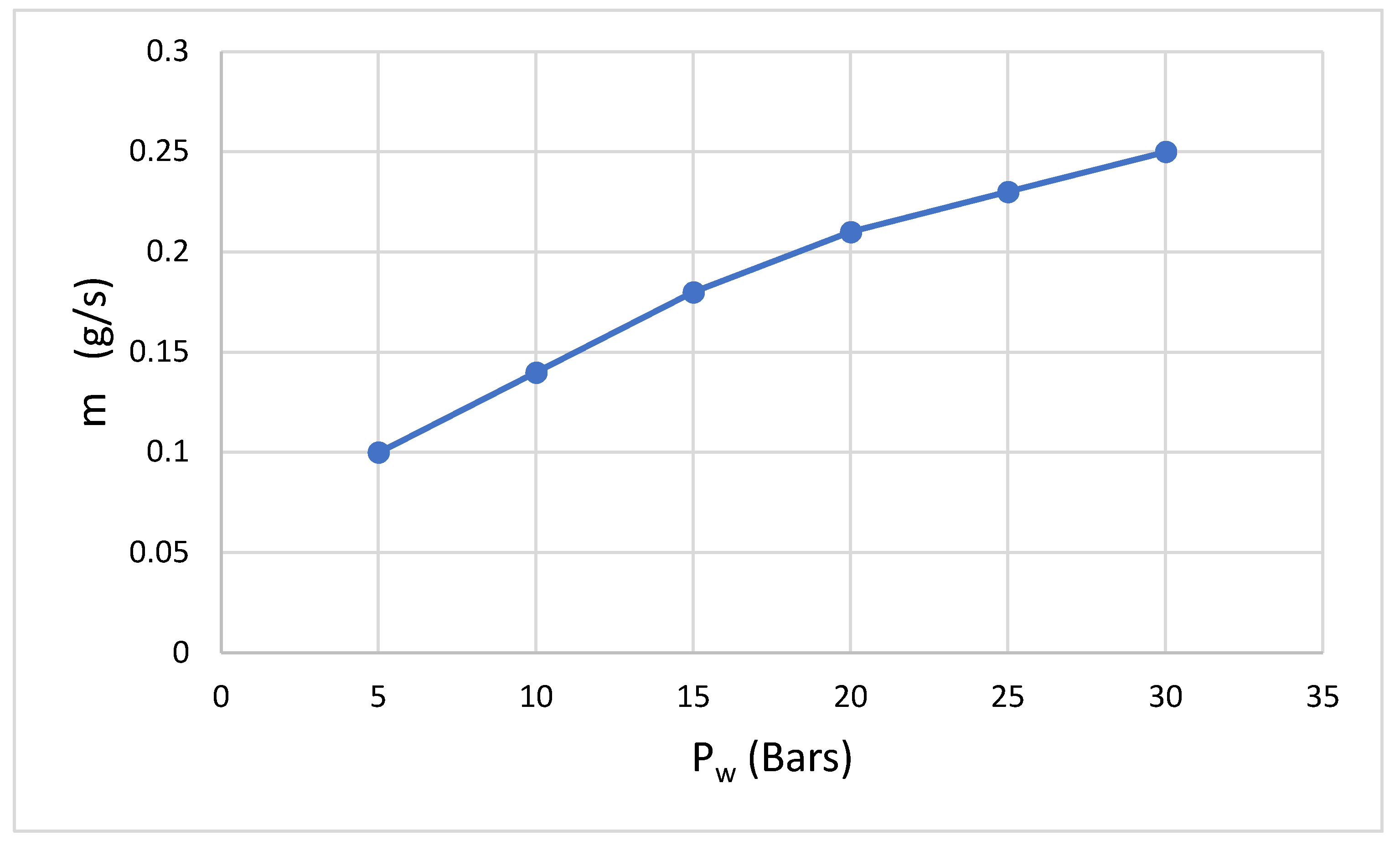
Figure 8.
Power of abrasive variation with pressure change.
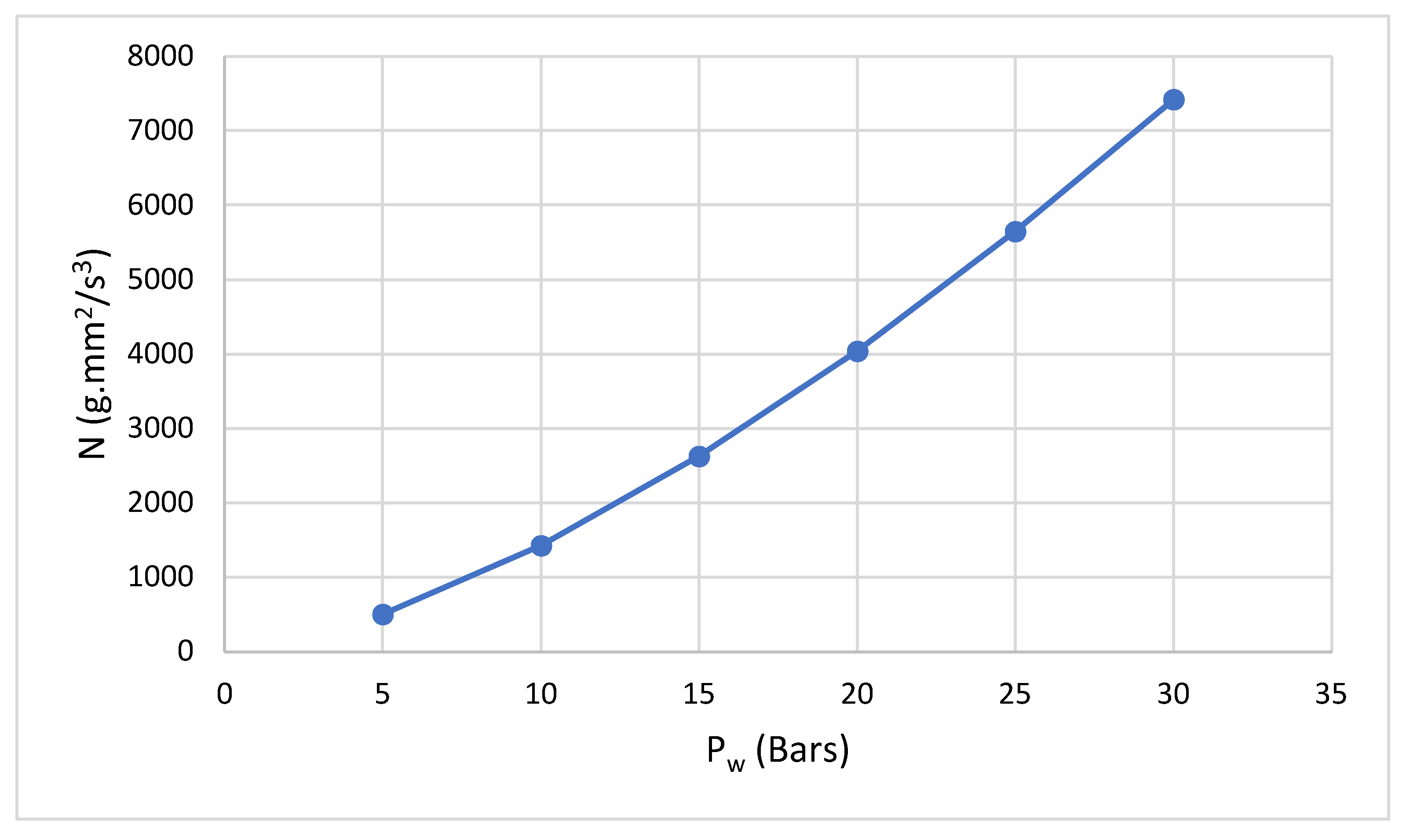
Figure 9.
Top view projection of the CNC frame with maximum force experienced by the structure.
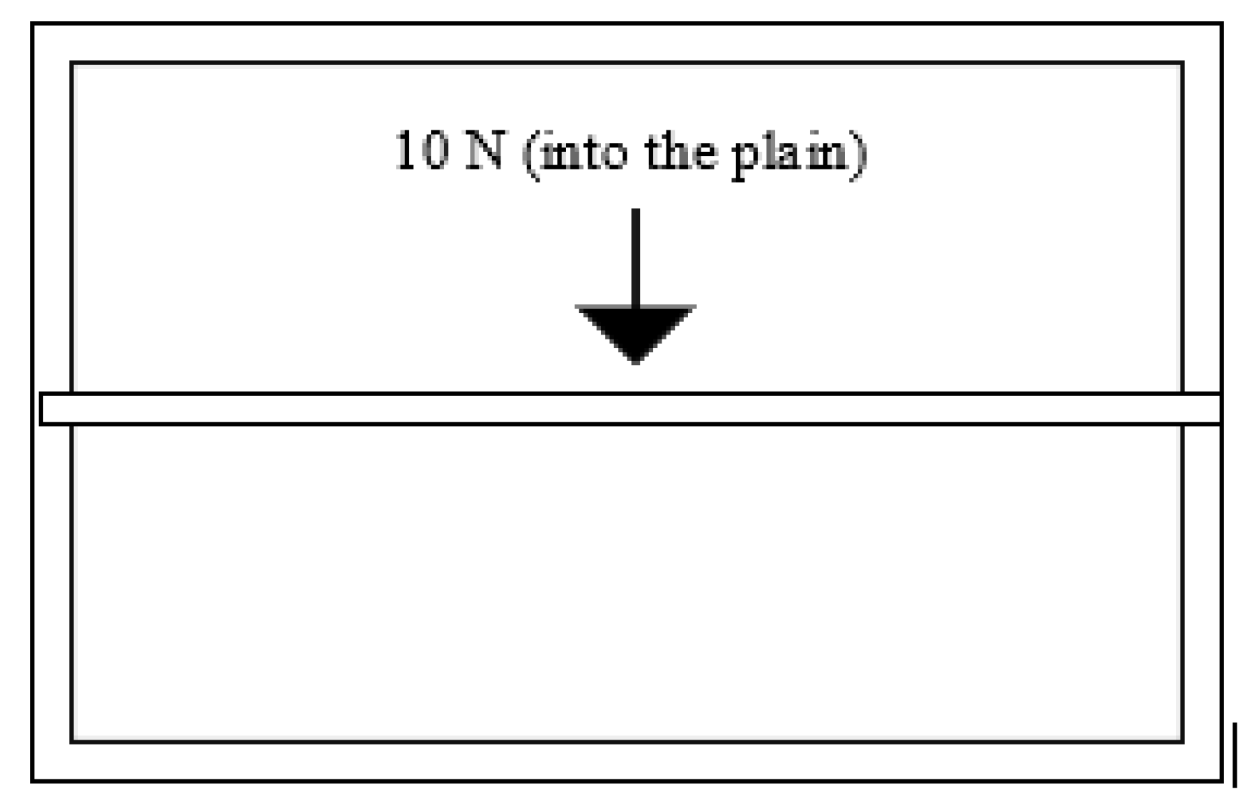
Figure 10.
Free body diagram of supporting column.
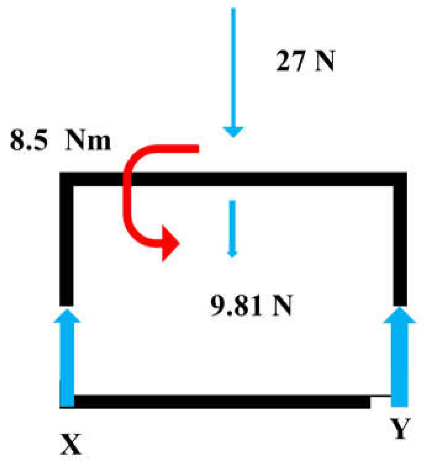

Table 1.
Rolling resistances.
| Force | Magnitude in N |
|---|---|
| Gross weight (N) | 27 |
| Rolling Coefficient (µ) | 0.01 |
| Total Rolling Resistance = F=µN | 0.27 N |
Table 2.
Linear accelerating forces.
| Quantity | Desired Value |
|---|---|
| Mass | 2.7 kg |
| Acceleration | 7 mm/s2 |
| Accelerating Forces | 0.0189 N |
Table 3.
Rotational speeds.
| Quantity | Desired theoretical Value |
|---|---|
| Linear Velocity | 7 mm/s |
| Radius | 2 cm |
| Rotational Speed rad/s | 0.35 rad/s |
| Rotational Speed RPM | 3.342 rpm |
Disclaimer/Publisher’s Note: The statements, opinions and data contained in all publications are solely those of the individual author(s) and contributor(s) and not of MDPI and/or the editor(s). MDPI and/or the editor(s) disclaim responsibility for any injury to people or property resulting from any ideas, methods, instructions or products referred to in the content. |
© 2024 by the authors. Licensee MDPI, Basel, Switzerland. This article is an open access article distributed under the terms and conditions of the Creative Commons Attribution (CC BY) license (http://creativecommons.org/licenses/by/4.0/).
Copyright: This open access article is published under a Creative Commons CC BY 4.0 license, which permit the free download, distribution, and reuse, provided that the author and preprint are cited in any reuse.


