Submitted:
22 April 2024
Posted:
23 April 2024
You are already at the latest version
Abstract
In the history of high-performance polymer composite parts with continuous in-plane fibre reinforcement, the comparatively moderate structural-mechanical properties in their out-of- plane-z-direction and the limited load carrying capability between individual reinforcement layers within the laminated structures have always been one of the greatest challenges. Plenty of research work has been carried out to improve load transfer capability as well as fracture toughness for crack opening events between the reinforcement layers by means of out-of-plane fibre reinforcement implementation, for example by sewing or z-pinning technologies. However, the results have not become established across a wide range of applications so far, because the technologies used have led to considerable losses of in-plane strength properties. In this paper first results are presented for a new method of a low fraction z-fibre reinforcement by means of very thin diameter laser drilled holes filled with short carbon fibres, demonstrating potential to improve Mode II fracture toughness.
Keywords:
Interlaminar fracture toughness
; Mode II
; z-pin reinforcement
; through-thickness fibre
; delamination
; laser drilling
1. Introduction
Continuously fibre reinforced polymer composites are well established for a large number of product applications since decades, mainly due to their excellent mass-related strength and stiffness properties. With the increasing social demand for a CO2-neutral and sustainable economy and the closing of material cycles, the need to develop new technologies to maximise the service life of technical products as well as to minimise the resources required for their manufacture and operation is also increasing [1]. Improved material properties, advanced manufacturing processes, adopted design principles and a comprehensive understanding of load cases are some of the most important factors that have led to more and more exploitation of the light weight design potential, especially for carbon fibre reinforced composites as they are commonly used for airframe structures today [2]. However, further thickness (and hence mass) reduction of structural parts is extremely difficult to achieve due to requirements linked to impact and repair events. In order to avoid expensive repair, composite airframe structures should provide sufficient damage tolerance against impacts originating from probable events such as e.g., hail, runway gravel or tool drop, and a certain minimum laminate thickness is necessary to achieve this [3,4,5,6]. Out-of-plane z-fibre reinforcements can improve both, the size of a resulting impact damage within the laminate as well as the residual laminate strength [7,8]. However, at the same time, they reduce in-plane properties, and through thickness reinforcements are not state-of-the-art for primary airframe series solutions today [9,10,11,12]. If repair of airframe structures is necessary, countersunk rivet solutions should be possible in order to maintain sufficient surface smoothness and to avoid unwanted aerodynamic drag [2]. A minimum laminate thickness is necessary to prevent unwanted rivet head pull through failure. This failure mode can be correlated with interlaminar shear strength [13] and it can therefore be assumed that improved interlaminar strength properties could enable thinner laminates for bolted repair solutions. An interesting attempt to improve the load transfer behaviour between the layers of a continuously fibre reinforced polymer composite proposed by Che et al. [14] is to apply a continuous z-fibre reinforcement with a very low fraction of z-pins (down to 0.16 vol%) and a very low z-pin diameter (down to 0.1 mm) in order to minimize unwanted reduction of the laminate in-plane properties. Results showed an increase of up to 176% of the Giic-value compared to the non-z-pinned reference laminate [14]. Z-pin insertion was achieved manually. As there are many studies published with continuous z-fibre reinforcement [7,15,16,17] with more or less potential for fast and efficient pin inserting technologies, only relatively few studies are available with discontinuous z-fibre reinforcement. Tatsuno et al. [18] have investigated the shear strength of thermoplastic welded joints modified with z-pins consisting of discontinuously carbon fibre reinforced polymer with a short carbon fibre length of 2 mm and z-pin diameters of 3 mm. One difficulty, however, was the flow behaviour of the melted short fibre-reinforced thermoplastic polymer in the prepared drill holes. Although the method may have the potential to increase the joint strength of welded composite parts, it must be assumed that the relatively large diameters of the z-pins applied in [18] have again a strong negative impact on the in-plane strength properties of the basic laminate. The aim of the present study was to investigate the potential improvements of the Mode II interlaminar fracture toughness of continuously fibre reinforced polymer composites by means of very thin diameter laser drilled holes, filled with short carbon fibre reinforced epoxy resin.
2. Experimental
2.1. Materials
In order to determine Giic-values samples were prepared according to DIN EN 6034. The prepreg material used was Cytec Cycom 977-2-34-12KHTS-134-1500 with a carbon fibre volume content of 58 vol%, an epoxy resin content of 42 vol% and a cured ply thickness of 125 μm. 24 layers of prepreg in 0 ° - orientation were stacked and vacuum bagged for a subsequent standard autoclave process, and a 150 μm thick film of Polytetrafluorethylene (PTFE) with a width of 50 mm was placed in the middle of the stack for later crack initiation. Vacuum was applied and samples were autoclave cured at 180 °C ± 5 °C for 180 min and a pressure of 7 bar, with heating and cooling rates of 2 °K/min. The samples were cut by means of a Mutronic Diadisc 5200 saw to a length of 127 ± 1 mm and a width of 25 ± 0.2 mm. The thickness was measured to 3.2 ± 0.1 mm. The length of the artificial crack created by the PTFE film in the middle of the samples was 40 mm ± 1 mm.
The base material for the production of the pins consisted of short carbon fibres and epoxy resin. Milled SIGRAFIL®C M150-3.0/200-UN fibres [19] with an average fibre length of 150 μm according to the manufacturer data sheet were used. The true length distribution of the short fibres was determined by means of a software-supported light microscopic analysis. 6 batches of short carbon fibres with a mass of 2.5 μg each were fully dispersed by means of 3 ml liquid, taken from a mixture of 100 ml distilled water and 3 ml of a household dishwashing detergent. 50-fold magnification images with a resolution of 1.022 μm / pixel taken by a Leica DM 6000 M microscope were used to determine the individual lengths of the fibre fractions. The distribution of the measured lengths can be seen in Figure 1.
The epoxy resin used for the z-pins was a mixture of EPIKOTE RIMR 935 resin and EPIKURE RIMH 936 hardener mixed in a volume ratio of 100:45. The viscosity of the mixture at room temperature is 320 mPas and the pot life is 240 min according to the manufacturer data sheet [20]. Liquid mixtures of resin and hardener with 10, 15 and 20 weight% short carbon fibres were prepared by stirring and subsequently degassed for several minutes by means of vacuum.
2.2. Laser Drilling
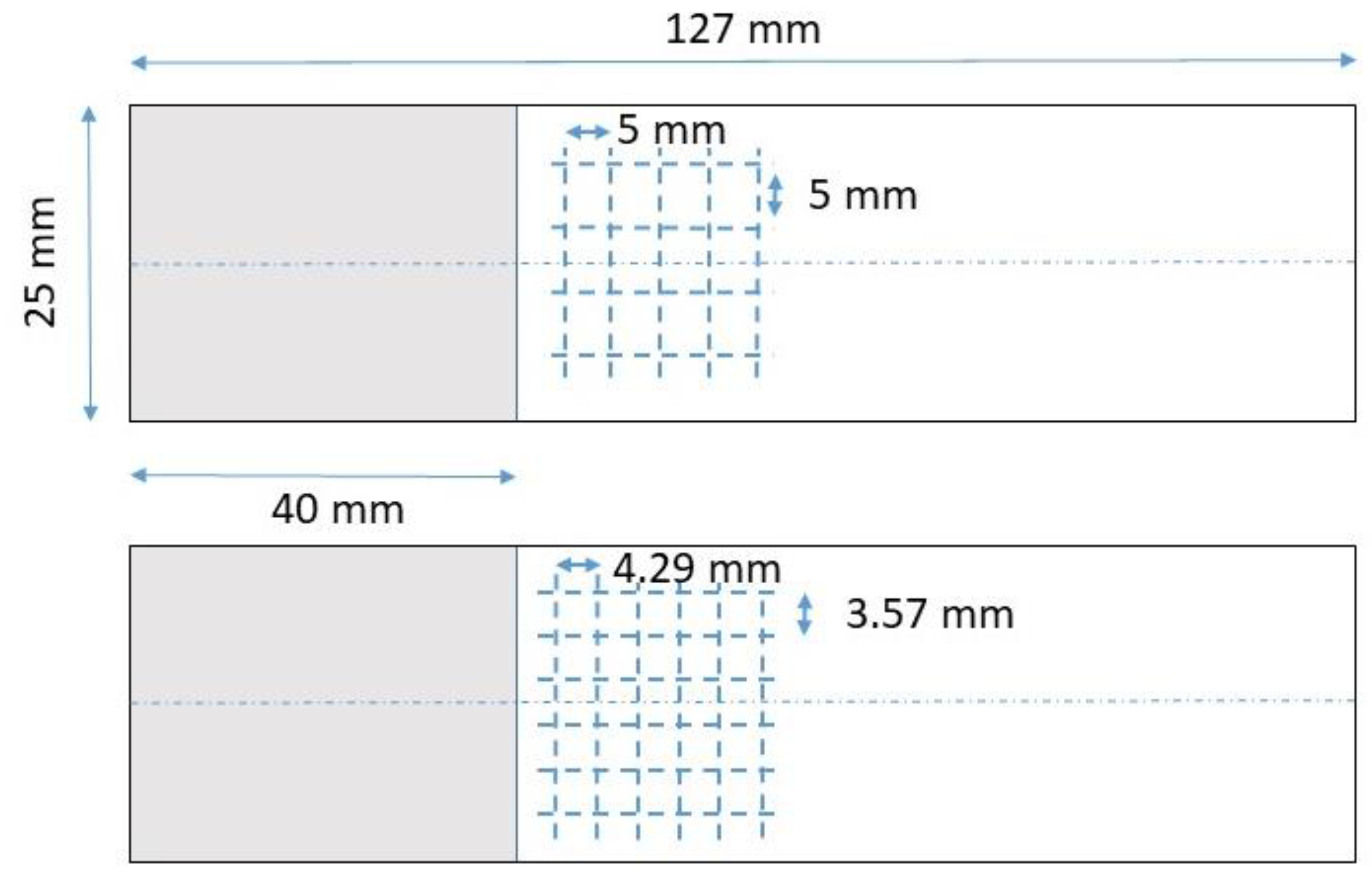
An ultrashort pulse laser with a wavelength of 532 nm was used to generate conical z-holes in the 3 mm thick cured CFRP samples. Process parameters at Institut für Oberflächen- und Schichttechnik GmbH Research Center OPTIMAS were adapted in order to achieve 2 different types of conical holes, the smaller one labelled with “Ps” with an intended outlet diameter target size (i.e., on the bottom side of the CFRP specimen) of 370 μm and the larger one labelled with “Pl” with an intended outlet diameter target size of 500 μm. For the smaller cones, a rectangular drilling pattern of 6 x 6 holes equidistantly spaced on each of the Giic specimen was selected, resulting in hole to hole and hole to edge distances of 3.57 mm crosswise, and 4.29 mm lengthwise. For the larger cones, a rectangular drilling pattern of 4 x 5 equidistantly spaced on each of the Giic specimen was selected, resulting in hole to hole and hole to edge distances of 5 mm crosswise, and 5 mm lengthwise.
Figure 2.
Size of Giic-Specimen and position of holes (z-pins) for 2 different hole sizes and drilling patterns: 4 x 5 larger holes “Pl” (top) with 500 μm outlet diameter target size and 6 x 6 smaller holes “Ps” (bottom) with 370 μm outlet diameter target size. The grey shaded areas indicate the position of the artificial crack in the middle of the samples.
A Zeiss Xradia 520 Versa X-ray microscope was used in order to determine volume and shape of the laser drilled holes, Figure 3. It was evident from this analysis as well as from additional light microscopy observations by a Leica DM 6000 M microscope that the intended, ideally circular entry opening cross section could not be maintained over the drilling depth, but instead, all samples showed an elliptical cross-section of the cone towards the end of the bore, with an inclination of the long elliptical side of 45° relative to the fibre orientation of the samples. The volume of the laser-drilled cone made visible by means of X-rays in Figure 3 shows two small lateral frays approximately in the centre. It is not clear whether these are due to thermomechanical effects of laser drilling or due to a zone of insufficient consolidation during the production of the CFRP samples in the autoclave.
The ellipse diameters a and b in Figure 3 determined were 326 ± 12 μm and 490 ± 7 μm for the bigger holes “Pl” with an inlet diameter d of 909 ± 7 μm, and 177 ± 10 μm and 339 ± 11 μm for the smaller hole “Ps” with an inlet diameter d of 787 ± 3 μm (mean values and scattering range for 12 samples measured for each drilling pattern). The volume content of the cones, i.e., also the intended volume content of the z-pin-reinforcement within the sample area of 25 mm x 30 mm (refer to drilling patterns shown in Figure 2) was calculated to approximately 1.2% for “Ps” and 1% for “Pl”.
2.3. Z-Pin Manufacturing
The 3 different mixtures of EPIKOTE RIMR 935 resin and EPIKURE RIMH 936 hardener with 10, 15 and 20 weight% short carbon fibres was applied on the surface of the drilled Giic-specimen by means of a spatula, and a needle with a diameter of 350 μm was used to insert the mixture. The specimen were covered by a PTFE film on the upper filling side of the samples to prevent the undesired intake of air into the cavities, and positioned on a peel ply on their lower side. Curing was achieved at 50°C for 24 hours. In preliminary tests, a vacuum of 0.6 bar and an autoclave overpressure of 7 bar were applied during cure, but the best filling results were achieved with unpressurised pre-curing at room temperature for 48 hours and subsequent post-curing at 50°C for 24 hours.
2.4. Mode II Testing
Three point bending tests were performed according to DIN EN 6034 in order to determine Giic crack opening energy release rates on a Zwick Retroline 1445 test machine, where the load was applied at a constant test speed of 1 mm/min. Deviating from the standard, the traverse stamp had a diameter of 20 mm instead of 25 mm. Tests were stopped if a 10% decrease of the maximum load achieved was reached. Giic-values were determined by Eq. 1, [21], where P is the load, a the initial crack length, d the traverse path distance, w the sample width and L the distance between the right and left support point, Figure 4. Load displacement curves were recorded for all samples. 5 samples were investigated for each of the 3 configurations: Non-z-pinned reference, Pl and Ps (ref. to Figure 2). 99% confidence intervals were calculated according to Eq. 2 [22], where t is the student distribution factor, μ the mean value, s the standard deviation and N the number of measurements.
3. Results
Figure 5 shows the results of the Mode II tests with mean values and the confidence interval of 99%. The untreated reference samples demonstrated a Giic-mean value of 3194 J/m2. The z-pinned samples showed a higher mean value of 3494 J/m2 (+ 10%) for the larger cones Pl and 3380 J/m2 (+ 6%) for the smaller cones Ps in smaller confidence intervals. A similar and statistically significant positive effect of the z-pin-reinforcement could also be confirmed by the calculation of the integral of the load-displacement curves, for which Pl showed a 12 % increase and Ps an 8% increase of the mean value. No significant changes of the maximum load (the initial failure load) were observed: The load was 1107 ±90 N within a 99% confidence interval for the reference samples, 1120 ±83 N for Pl and 1082 ±18 N for Ps. Note that the distance between the end of the artificial crack (i.e., the starting position of the induced Mode II crack) and the first row of z-pins was slightly different for Pl and Ps with 5 mm and 4.29 mm respectively.
A fracture surface analysis of Giic tested specimen by exposure of the samples in liquid contrast agent and subsequent x-ray analysis demonstrated differences in both, crack front formation and fracture surface size, Figure 6. While the untreated reference samples clearly had the largest fracture surface (although the lowest Giic-values) with a rather straight crack front, the z-pinned samples showed crack stopping functions by a wave-like crack front profile and smaller total fracture surfaces.
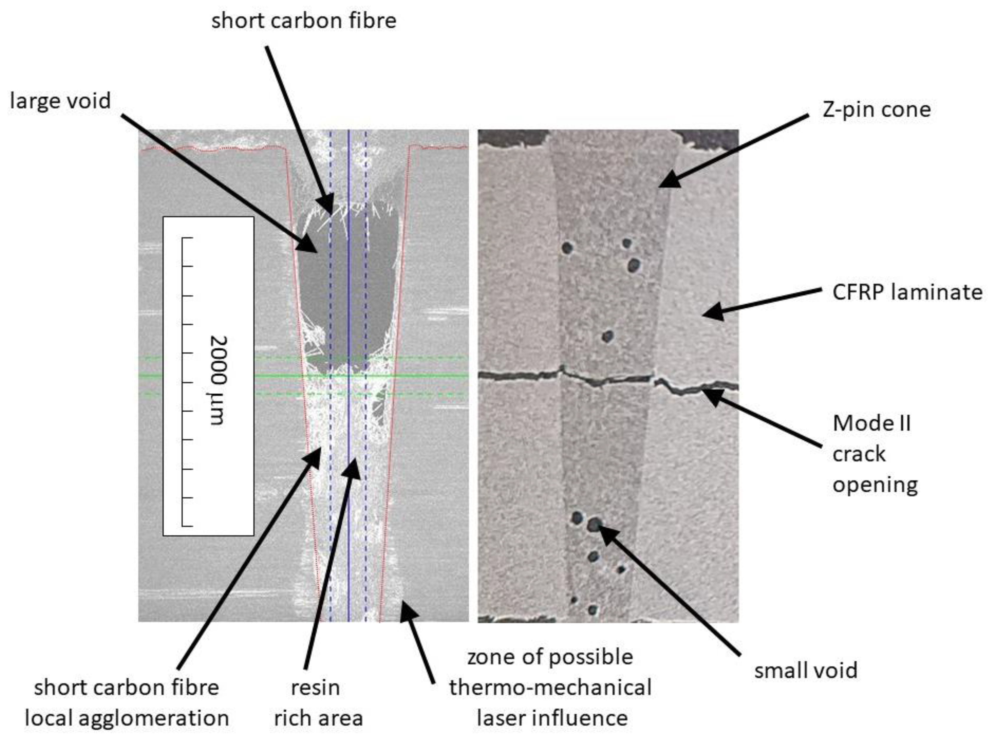
It is interesting to note that these results were achieved with the lowest content of short carbon fibres of only 10 weight% used for the z-pins due to the fact that it has turned out to be quite challenging to completely fill all laser drilled cones by the liquid resin-fibre mixture with 15 or even 20 weight % of short carbon fibres. Figure 7 shows x-ray imaging results of a non-fractured (left) and fractured (right) z-pin. It is obvious that the z-pins are not free of voids (air inclusions), and that the distribution of the short carbon fibres is not homogeneously in every case but can show local agglomerations. Even better Giic results seem likely if the filling of the cones and the fibre distribution could be improved. Although it is encouraging to see that even relatively “long” short carbon fibres could be inserted into the cones (Figure 7, left image, upper part of the z-pin), it should also be noted that the intended preferred direction of these fibres in z-direction as it was originally assumed to occur due to the viscous flow and edge friction effects of the conical hole could not be observed so far. Finally, it should be noted that a relatively large portion of the short carbon fibres used might have well been below the critical fibre length, refer to Figure 1. A calculation of the critical fibre length lc according to Eq. 3 where σf is the fibre strength set to 3 GPa, df the fibre diameter set to 7 μm, τB the fibre-matrix interface shear strength assumed with approximately 62 MPa leads to a value of approx. 170 μm. This would mean that a large portion of short carbon fibres in the z-pins would act rather as a weakening of the epoxy resin instead of a reinforcement. On the other hand, this again reveals some additional potential of the new method demonstrated here, if in future it will be possible to work with better resin-fibre mixtures that do not fall below the critical fibre length.
4. Summary and Conclusion
The potential of a z-pin reinforcement of CFRP laminates with a very low z-pin volume content of approximately 1 % and very small z-pin diameters well below 1 mm was investigated. Conical holes were laser drilled and injected with short carbon fibre reinforced liquid epoxy resin. Giic samples with different z-pin diameters and drilling patterns were prepared and tested according to DIN EN 6034. Results showed an increase of the Giic-values of 10 % in average for samples with conical z-pins of approximately 0.9 mm to 0.3 mm diameter and a decrease of the fracture surface compared to a non-pinned reference. These results were achieved with z-pins consisting of an only 10 weight% short carbon fibre reinforced epoxy. In future research work it has to be demonstrated that –different to state of the art sewing or z-pinning technologies with their well known negative impact on in-plane fibre orientation or their notch effects- the relatively thin pin diameters of only a few tenths of a millimetre with holes generated by laser drilling and the relatively low volume fraction of the z-pins will lead to minor or even negligible influence on important in-plane-properties, and that by inhibiting crack propagation also the impact behaviour of thin CFRP laminates can be improved. Focus should be put on design allowables most relevant for airframe design, such as open- and filled hole tension and compression as well as pin loaded bearing and compression after impact strength values.
Funding
The work carried out for this study was financed with own resources at Leibniz-Institut für Verbundwerkstoffe GmbH. As a member of the Leibniz Association, the institute receives institutional grants in accordance with the AV-WGL for the joint financial support of institutions by the federal and state governments (federal share 50%, share of the state of Rhineland-Palatinate and the entirety of the German states 50%).
Conflicts of Interest
The authors declare no conflict of interest.
Data Availability Statement
The raw data required to reproduce these findings cannot be shared at this time as the data also forms part of an ongoing study.
References
- EU, “European Green Deal,” [Online]. Available: https://ec.europa.eu/commission/presscorner/detail/en/ip_20_1669.
- U. P. Breuer, Commercial Aircraft Composite Technology, Switzerland: Springer International Publishing, 2016.
- X.-S. Yi, “Development of multifunctional composites for aerospace application,” in Multifunctionality of Polymer Composites, Oxford, Elsevier, 2015, pp. 367-415.
- G. A. O. Davies and R. Olsson, “Impact on composite structures,” The Aeronautical Journal, pp. 541-563, 2004, 108 (1089).
- C. D. Stavropoulos and G. C. Papanicolaou, “Effect of thickness on the compressive performance of ballistically impacted carbon fibre reinforced plastic (CFRP) laminates,” Journal of Materials Science, pp. 931-936, 1997, 32 (4). [CrossRef]
- Gilliot, Matrix influence on the impact tolerance of carbon composites made of non-crimp fabric, Dissertation, Magdeburg: DLR Forschungsberichte, 2010.
- A. P. Mouritz, “Review of z-pinned composite laminates,” Composites Part A: Applied Science and Manufacturing, pp. 2383- 2397, 2007, 38 (12). [CrossRef]
- G. Freitas, C. G. Freitas, C. Magee, P. Dardzinski and T. Fusco, “Fiber insertion process for improved damage tolerance in aircraft laminates,” Journal of Advanced Materials, pp. 36-43, 1994, 25.
- M. Knaupp and G. Scharr, “Manufacturing process and performance of dry carbon fabrics reinforced with rectangular and circular z-pins,” Journal of Composite Materials, pp. 2163- 2172, 2014, 48 (17). [CrossRef]
- A.Mouritz, K. H. A.Mouritz, K. H. Leong and I. Herszberg, “A review of the effect of stiching on the in-plane mechanical properties of fibre-reinforced polymer composites,” Composites Part A: Applied Science and Manufacturing, pp. 979-991, 1997, 28 (12). [CrossRef]
- P. Chang, A. P. Mouritz and B. N. Cox, “Properties and failure mechanisms on z-pinned laminates in monotonic and cyclic tension,” Composites Part A: Applied Science and Manufacturing, pp. 1501- 1513, 2006, 37 (10). [CrossRef]
- Tong, L.; Mouritz, A.P.; Bannister, M.K. 3D Fibre Reinforced Polymer Composites; Elsevier BV: Amsterdam, NX, Netherlands, 2002. [Google Scholar]
- U. D. o. Defense, Composite Materials Handbook MIL-HDBK-17-1E, 2005.
- Z. Che, M. Z. Che, M. Li, S. Wang, Y. Wang, Y. Gu and W. Zhang, “Mode II interlaminar fracture toughness enhancement for fine z-pin reinforced carbon fiber composite with low fraction of pins,” Polymer Composites vol 43, no. 5, pp. 2992-3002, 2022. [CrossRef]
- K. Partridge and D. D. R. Cartié, “Delamination resistant laminates by z-fiber pinning: Part I manufacture and fracture performance,” Composites Part A: Applied Science and Manufacturing, pp. 55-64, 2005, 36(1). [CrossRef]
- P. Chang, The mechanical properties and failure mechanisms of z-pinned composites, Dissertation, Melbourn: School of Aerospace, Mechanical Manufacturing Engineering, RMIT University, 2005.
- Lander, Designing with z-pins:locally reinforced composite structures, Dissertation, Cranfield: Composite Centre Cranfield University, 2008.
- D. Tatsuno, R. D. Tatsuno, R. Tanaka and T. Yoneyama, “Through-Thickness Fiber Formation Integrated into Carbon-Fiber-Reinforced Thermoplastic Laminate Welding Method,” Journal of Materials Engineering and Performance Vol 31 (12), pp. 9615-9629, 22 May. [CrossRef]
- S. Carbon, “Die Verstärker: Unsere Carbonkurzfasern,” Available online:. Available online: https://www.sglcarbon.com/loesungen/material/sigrafil-carbon-kurzfasern (accessed on 17 January 2024).
- HEXION, “Technical Data SheetEPIKOTE™ Resin MGS RIMR 935 and EPIKURE™ Curing Agent MGS RIMH 936- 937,” Available online:. Available online: https://airheart.ca/wp-content/uploads/2020/02/935TDS.pdf. (accessed on 17 January 2024).
- A. Carlsson, D. F. A. Carlsson, D. F. Adams and R. B. Pipes, Experimental characterization of advanced composite materials (Fourth Edition), London New York: CRC Press Taylor & Francis Group, 2024.
- F. León, Messtechnik, Berlin, Heidelberg: Springer, 2019.
Figure 1.
Measured results of the short carbon fibre length distribution. The shortest fibre was 17 μm, the longest 487 μm, the arithmetic mean value was 116 μm with a standard deviation of ± 91 μm. In addition to a manual fibre count and measurement, 7 images were analysed by a software each with 82 to 155 identified fibres. More than 50 % of the fibres had a length below 100 μm, only 24 % of the fibres had a length above 170 μm.
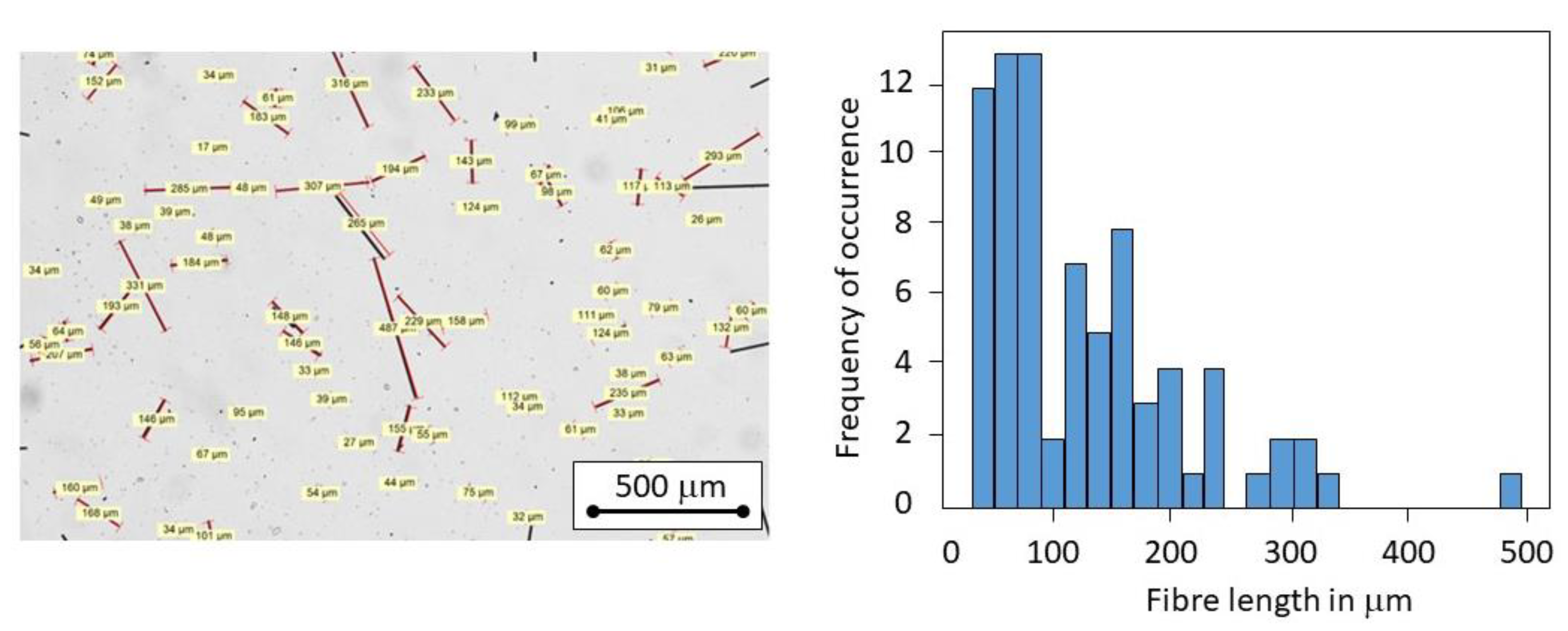
Figure 3.
X-ray microscope image of the conical laser drilled hole volume with circular initial cross section and elliptical outlet cross section.
Figure 3.
X-ray microscope image of the conical laser drilled hole volume with circular initial cross section and elliptical outlet cross section.
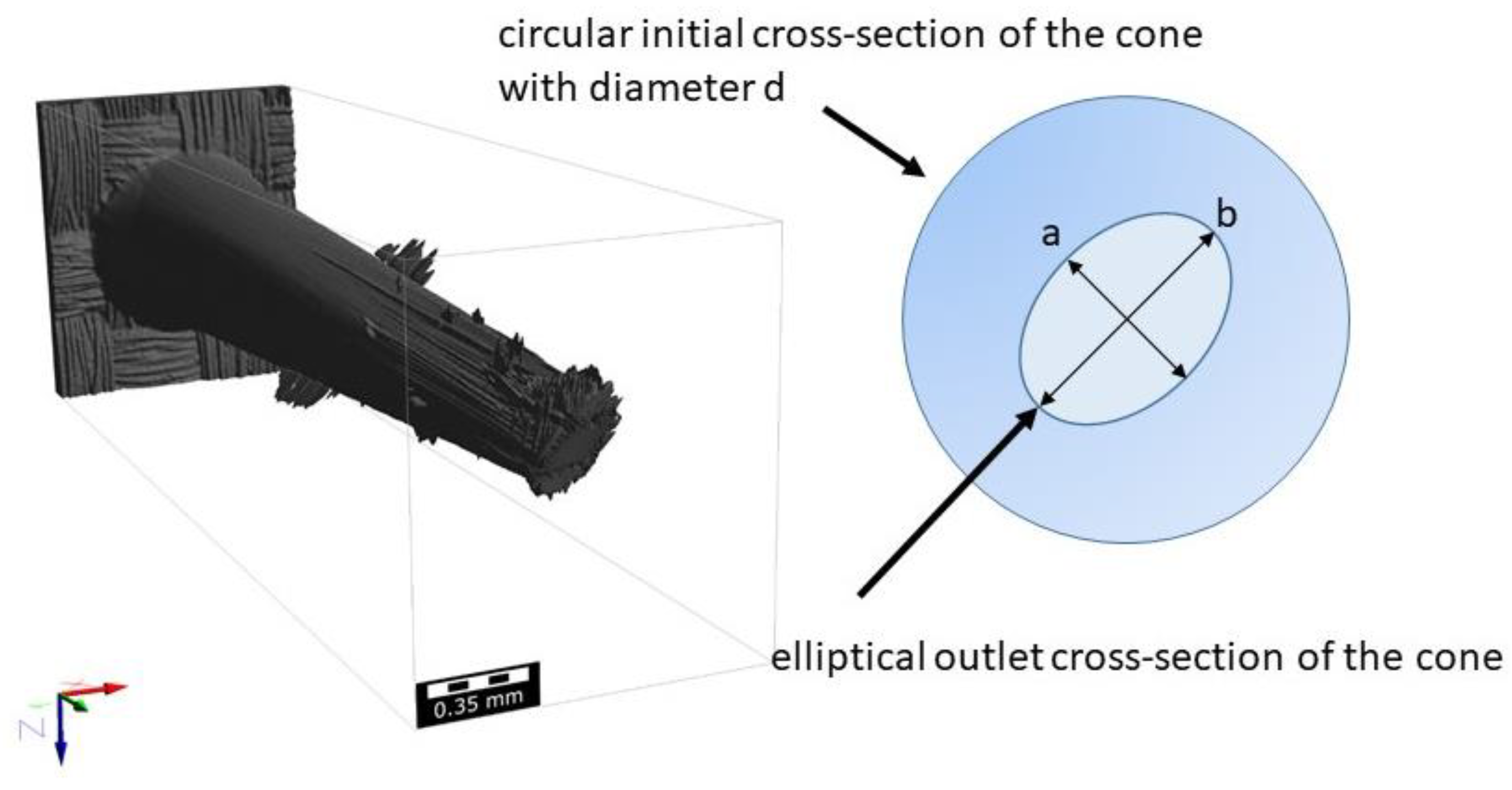
Figure 4.
Mode II test set up according to DIN EN 6034.
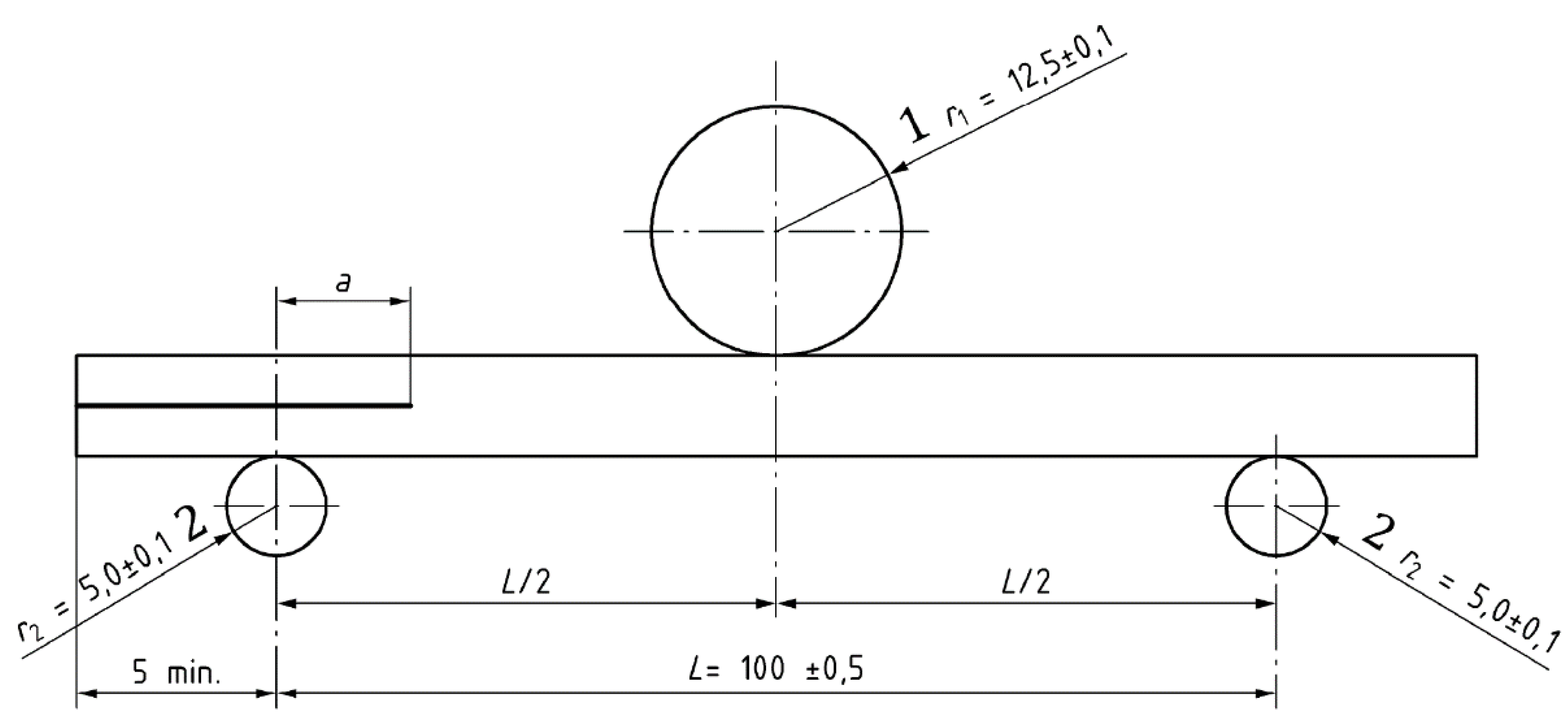
Figure 5.
Mode II test results for reference specimen (without z-pinning, left) and specimen with z-pins manufactured with a 10 weight% short carbon fibre reinforcement epoxy resin of larger Pl (middle) and smaller Ps (right) pin diameter. The specimen volume content of the z-pin-reinforcement within the crack-relevant sample area was approximately 1% for Pl and 1.2% for Ps.
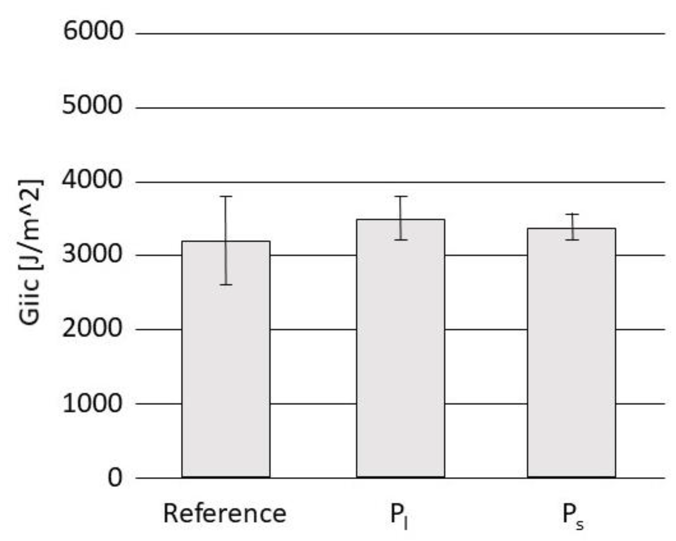
Figure 6.
Fracture surface analysis of tested Giic specimen by exposure to liquid contrast agent and subsequent x-ray microscopy image analysis for untreated reference (left), Pl (middle) and Ps z-pinned specimen. The red dotted line is equivalent with the position of the crack initiation. The Pl and Ps samples shown had a 10 weight% short carbon fibre reinforcement in the z-pins.
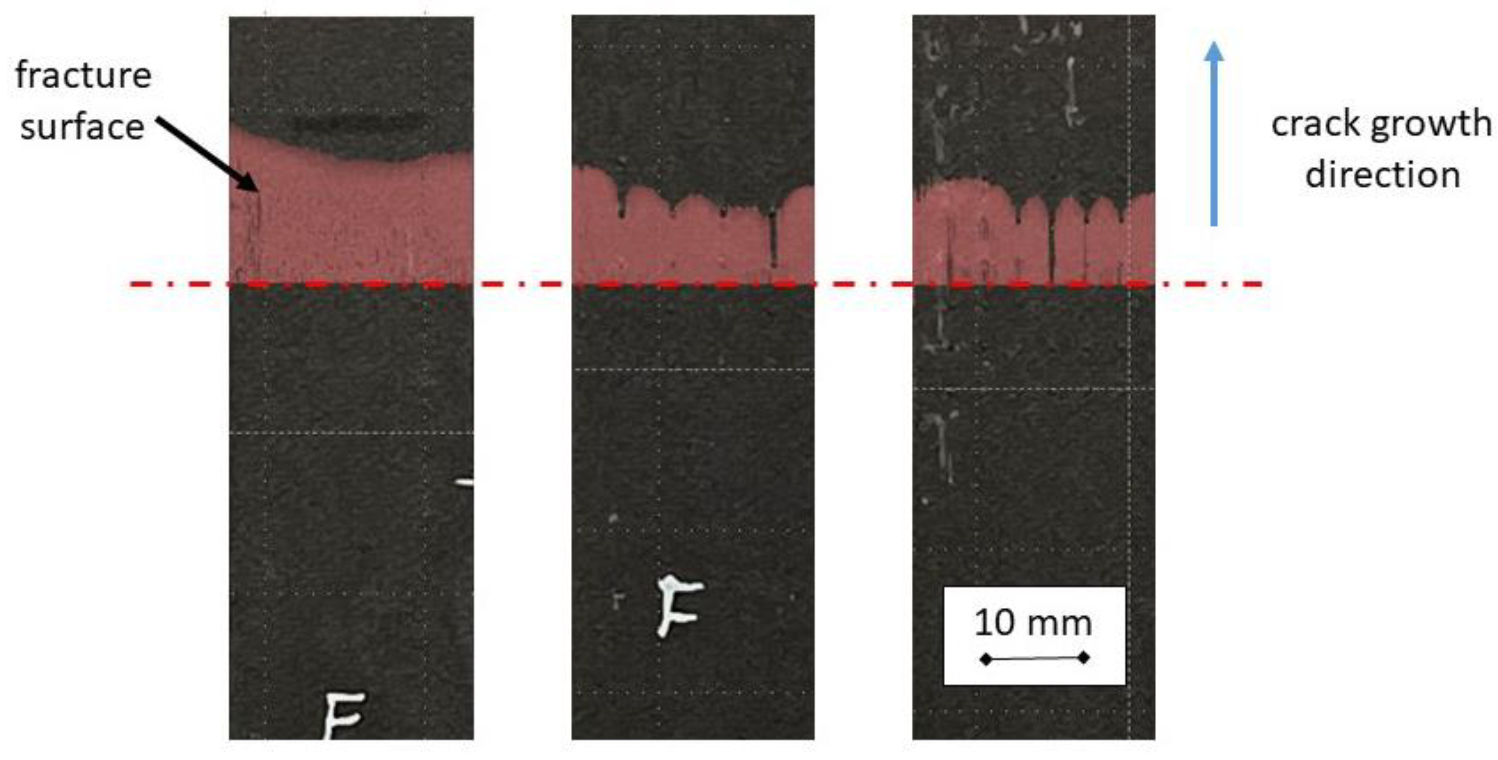
Figure 7.
X-ray images of short carbon fibre reinforced z-pins before (left) and after (right) Giic-testing. Images were taken from different Ps specimen and positions. Red dotted lines indicate the sample and cone edges. The z-pin of the right image is thoroughly filled and shows only very small inclusions of voids and a relatively homogeneous fibre distribution; the z-pin on the left shows a large void and a more inhomogeneous fibre distribution. Both z-pins were manufactured with a 10 weight% short carbon fibre reinforced epoxy.
Disclaimer/Publisher’s Note: The statements, opinions and data contained in all publications are solely those of the individual author(s) and contributor(s) and not of MDPI and/or the editor(s). MDPI and/or the editor(s) disclaim responsibility for any injury to people or property resulting from any ideas, methods, instructions or products referred to in the content. |
© 2024 by the authors. Licensee MDPI, Basel, Switzerland. This article is an open access article distributed under the terms and conditions of the Creative Commons Attribution (CC BY) license (https://creativecommons.org/licenses/by/4.0/).
Copyright: This open access article is published under a Creative Commons CC BY 4.0 license, which permit the free download, distribution, and reuse, provided that the author and preprint are cited in any reuse.


