Submitted:
17 April 2024
Posted:
18 April 2024
You are already at the latest version
Abstract
The article studies and analyzes a hybrid power source system, lithium battery, and fuel cell assisted by flexible photovoltaic panels for hybrid electric vehicles (HEVs). The new configuration operates based on optimizing the performance of the dual power source to maximize the available energy and operating time. The operational mode simulates specific driving conditions in urban, peripheral, and intercity routes under variable driving patterns and traffic conditions. The simulation results show that the new configuration increases the hybrid electric vehicle performance, providing higher reliability despite the more complex design. The proposed system reduces the external power supply dependence and avoids unexpected sudden stops due to energy exhaustion. The new configuration also extends the vehicle driving range depending on driving mode and route conditions. The vehicle driving range extension may reach up to 276.3 km. The hybridization of fuel cells with lithium battery and PV panel assistance enhances battery management, reducing battery servicing and increasing lifespan. The proposed topology is cheaper than a single fuel cell power system by 17.2%, reducing the total cost related to the single battery power system if we consider the battery recharge for its entire lifespan. The cost saving is 2.6% for the American market and 14.8% for the European one.
Keywords:
Hybrid Electric Vehicle
; Dual Power Source
; Renewable Energies
; Lithium Battery
; Fuel Cell
; Photovoltaic System
; Battery Management
; Driving Range
; Efficiency Improvement
; Cost Saving
Introduction
Electric vehicles represent an alternative to internal combustion engine cars for reducing fossil fuel dependence, preserving the environment, and contributing to carbon emissions reduction [1,2,3,4]. Electric vehicles offer various configurations depending on the power source, with battery electric vehicles (BEV) representing the most popular option [5,6,7].
An alternative solution for the electric vehicle (FEV) is the fuel-cell electric vehicle (FCEV), which operates under a hydrogen supply basis [8,9,10]. Despite BEV being the most extended version of FEV, fuel-cell electric vehicles are gaining popularity as fuel-cell research is improving and car manufacturers are offering new models with competitive characteristics compared to BEVs [11,12,13,14].
Battery electric vehicles have been extensively studied and characterized and continue improving to achieve higher performance, longer lifespan, and extended driving range, one of the principal users’ worries [15,16,17,18]. Despite the low implementation of fuel-cell electric vehicles in the automobile market, the new advances in fuel-cell research and technology make them an alternative for the future electric vehicle since hydrogen is abundant, and the residue, water vapor, does not generate environmental impact [14,19].
Hybrid configuration in electric vehicles is not new since battery electric vehicles assisted by photovoltaic energy, called vehicle integrated photovoltaics (VIPV) [20,21,22,23], already exists in commercial versions [24,25]. Nevertheless, this hybrid configuration is not very popular due to the low energy density of PV panels compared to the battery and the complexity of the hybrid design. Despite these drawbacks, researchers continue investigating how to improve the PV-BEV’s performance, especially the driving range [26].
Hybrid BEV-FCEV does not exist in commercial versions but is the subject of many research works, currently under the battery/fuel-cell/ultra-capacitor topology [27,28,29]. The great advantage of this configuration resides in the benefitting effects of using the battery for high power demand and fuel cells for medium and lower power requirements when a high-rate battery and a fuel cell are combined to supply energy for vehicle traction [30].
The hybridization of fuel cells and PV panels is barely studied. A prospective research deals with hybrid photovoltaic fuel cell/battery bank system [31,32,33]. Nevertheless, a system including a built-in electrolyzer is not yet explored, maybe due to the technology complexity of installing an electrolyzer connected to the PV panel for in-situ hydrogen generation. Among the problems derived from the use of fuel cells in electric vehicles, we can mention the hydrogen storage system, which represents a security problem if operated in pressurized tanks [34,35,36,37,38]. We can partially solve this problem by reducing the tank pressure; however, the lower the tank pressure, the shorter the FCEV autonomy.
This work proposes hybridizing a PV panel, a battery, and a fuel cell to power electric vehicles. Each power source is responsible for supplying energy under specific conditions, so they complement each other to optimize the hybrid system operation. The basis of this new idea is assembling the three systems in one, which makes the electric vehicle run under variable driving conditions for optimum performance, longer driving range, and higher durability.
Electric Vehicle Prototype Topology
Hybrid electric vehicles (HEVs) currently use an internal combustion engine and an electric motor powered by a lithium-ion battery [39,40]. Alternative topologies for HEVs consist of a combination of non-pollutant power sources, thus avoiding internal combustion engine use [41,42,43,44,45]. The diagram of Figure 1 shows the topology structure for HEVs.
PV and SC account for photovoltaic and super-capacitors. ICE only appears in the battery section because it is the only available commercial option. For our study, we selected the rounded option with a circle.
Fuel cell requires a continuous hydrogen supply, which we obtain from a pressurized tank, a hydrogen storage system in metal hydrates, a hydrocarbon reformer unit, or an electrolyzer [8,46,47,48,49]. Pressurized hydrogen shows the advantage of a high energy density, depending on the tank pressure, and long working time if we operate a large tank size. The gaseous hydrogen storage, however, is subjected to severe security precautions due to the explosion risk since the hydrogen is highly dangerous [50,51,52]. We can store the hydrogen in metal hydrates to avoid explosion risk; metal hydrates are not flammable and use less space than pressurized tanks. Metal hydrates have some limitations when it comes to releasing hydrogen during the desorption process, and they may not be the most efficient in adsorbing and desorbing hydrogen [36,53,54,55]. Direct hydrogen generation by electrolysis is a rapid, efficient, and safe method of generating gaseous hydrogen, having the problem of needing an in-situ electrolyzer for hydrogen flow generation to make the fuel cell work. This new technique contrasts with the up to now used methods to obtain hydrogen from methanol and propane, or ammonia. [56,57].
We select the last option, avoiding the pressurized hydrogen tank risk and the limited efficiency of hydrogen storage in a metal hydrate system. Therefore, the topology of the system consists of a lithium battery pack, a proton-exchange membrane fuel cell with an electrolyzer, and a vehicle rooftop photovoltaic system. Figure 2 shows the schematic view of the electric vehicle topology.
Hybrid System Characteristics
- a)
- Photovoltaic panel
Electric vehicle motor operates at a voltage between 360 V and 480 V, although recent models elevate the working voltage to 800 V [58,59,60,61]. Power sources should match operating voltage to avoid energy losses in the voltage conversion process; indeed, the higher the voltage conversion rate, the higher the energy losses [62,63,64].
Since photovoltaic panels currently operate in the range 12V to 48 V for a single panel, matching the electric motor operational voltage requires arranging in series PV panels until reaching the specific voltage; in our case, the number of panels in series is:
Vel and VFV are the electric motor and photovoltaic panel working voltage.
In our case, considering an electric motor of 480 V, and a 48V PV panel:
PV panel standard size depends on output maximum power [65,66]. Considering that the average power density is constant, around 200 W/m2, for a vehicle with an average rooftop size of 2.5 m2, we can install a panel of 500 W [67]. However, since the vehicle rooftop is not flat, the most adequate solar panel is a curved one (Figure 3), which increases the effective area due to its curvature [68].
Modern curved solar panel has a curving factor of 0.78, on average. Therefore, the effective area is:
In our case:
This surface allows a PV panel of 640 W.
If we use the car hood for PV panel installation, the effective surface increases by a factor of 1.8, thus allowing a PV panel system of 1152 W.
The energy generated by a PV system depends on the peak sun hours (psh) value, which depends on the location and day of the year. Since location depends on latitude and day of the year on declination, we should know these two parameters to determine the energy generation by the PV system.
A current practice to simplify the calculation is using the typical day of the month, thus reducing the whole year to twelve values, one per month [69].
Figure 4 shows the evolution of the energy generated by the rooftop and hood car photovoltaic installation. We consider the average declination value for the entire month.
We observe that photovoltaic energy generation moves in the range 2.6 kWh to 6.6 kWh. Considering an average latitude of 30º, and averaging the energy generation for the entire year, we obtain 5.2 kWh.
- b)
- Lithium battery
Lithium batteries are responsible for vehicle traction at the most demanding power-driving conditions, acceleration and uphill road; therefore, we can determine the battery energy capacity from the required maximum dynamic force and average vehicle speed. Mathematically:
The maximum dynamic force corresponds to the route segment where the vehicle is accelerating and/or climbing an uphill road:
m, a,v and <v> are the mass, acceleration, current and average vehicle speed, κ and μ are the drag and rolling coefficient, and α is the road slope.
Expressing the drag coefficient in terms of aerodynamic coefficient:
Cx is the vehicle aerodynamic coefficient, Af is the front area, and ρair is the air density.
A light-duty vehicle, including all the elements configured in Figure 2, weighs approximately 1900 kg [70]. This value differs depending on the manufacturer’s model, although the weigh reduces by 200 kg if we select the appropriate fuel cell system [71].
Considering a moderate driving pattern, characterized by an acceleration of 1.75 m/s2 [72], an aerodynamic coefficient of 0.29 [73], a rolling coefficient of 0.015 [73], and an average road slope of 2% (α=1.1º) [74], for average vehicle speed of 40 km/h in urban route [75], we have:
The required maximum power for a peak vehicle speed of 70 km/h, a current traffic limit in many urban areas [76], is:
This power corresponds to 105.3 CV (103.9 HP), which matches many light-duty vehicles’ engine power of similar characteristics [77].
Electric vehicle battery supplies the required energy for the electric engine. Nevertheless, to obtain the battery power and energy capacity, we should apply energy losses derived from transmission system and battery discharge; therefore:
In current conditions, transmission and battery discharge efficiency is 0.855 [78,79,80,81,82] and 0.95 [83,84]; replacing in Equation 10 and using data from Equation 9:
If we apply the WLTP protocol [85] to determine the time interval the vehicle submits to the maximum power requirement, we obtain a time fraction of 8.494%. Retrieving data from the literature, the average daily trip distance is 35 km [86]; therefore, for an average speed of 40 km/h, the daily travelling time is:
If we apply the battery fraction use to the daily traveling time, the daily battery time use is:
The required energy from the battery during this working time is:
Equation 14 provides the theoretical minimum battery energy capacity to cover energy demand for acceleration and uphill road.
Batteries, however, suffer from capacity modification depending on discharge rate according to the expression [87]:
Cr and Cn represent the real and nominal battery capacity. Coefficients a and b are empirical constants depending on battery type; for lithium-ion a=0.9541 and b=0.0148 [87].
Battery energy capacity depends on battery capacity and voltage as:
Because the battery voltage remains constant:
Replacing values from our prototype, we have:
Combining Equations 15, 16, and 18 and considering the battery voltage, the battery capacity results:
We must determine the battery discharge rate, XC, to evaluate if the battery stands for the maximum required power; applying data from our prototype:
A discharge rate of 12.3 is fully compatible with lithium battery performance.
- c)
- Fuel cell
Fuel cell power for electric vehicles depends on the type of cell used for electricity generation; in our case, we use an electrolyzer whose power range is 5 W to 250 kW [88], matching the required maximum power for our prototype. An alternative is a methanol reformer unit.
According to chemical reactions, the methanol reformer is more efficient since it produces three hydrogen moles per methanol unit, while the electrolyzer only produces two hydrogen moles per mole of water. Nevertheless, considering a fuel tank, methanol, or water of identical volume, the electrolyzer is more efficient since it produces 55.6 moles of hydrogen when using the electrolyzer and only 49.5 moles in the case of a methanol-reformer.
The gap in hydrogen generation comes from the difference in density between methanol and water, 792 kg/m3 and 1000 kg/m3 [89,90]. Considering methanol and water molecular mass [89,90]:
For a conventional light-duty vehicle 40 liters tank:
We consider hydrogen as an ideal gas, occupying 22.7 liters per mole.
Fuel cell operates when battery is deactivated, and vehicle is not working on energy recovery mode. Previous work studied the required energy distribution associated to inertial, drag, rolling and weight forces [91]; the results analysis shows that the vehicle only requires 20% of the maximum power to stand for drag and rolling forces. Therefore, the fuel cell should have a supplying power of:
The energy supplied by the fuel cell is:
Which corresponds to the following daily hydrogen flow:
eH2 is the hydrogen specific energy.
Replacing data for our prototype:
Considering the energy required by the fuel cell and an electrolyzer efficiency of 0.8 [92], the necessary power to make the electrolyzer work, Pely, is:
On the other hand, retrieving efficiency data from commercial electrolyzer units [93,94,95], we obtain:
We observe the good agreement between the two calculation methods, within 93.5% accuracy, which proves the quality of the calculated value. Comparing data from Equations 29 and 30 with the expected power demand from the fuel cell (Equation 25), a deviation of 8.6% occurs, which is attributed to inaccuracy in calculating the fuel cell operating time fraction from WLTP protocol.
Energy Balance
For a daily cycle, the proposed prototype requires a total power of 107.8 kW to operate the battery and fuel cell, with a combined energy capacity of 20.54 kWh. The solar photovoltaic system generates 5.2 kWh daily. Table 1 resumes the power and energy hybrid system characteristics.
We realize that the photovoltaic system cannot stand for battery or fuel cell power or energy demand; besides, even with a charged battery, the combined energy of the PV system and battery cannot match the fuel cell energy demand. Therefore, since we cannot enlarge the PV system size or reduce the fuel cell energy requirements, we should increase the battery capacity to compensate for the system energy unbalance.
Since the energy imbalance is 3.51 kWh, the new battery capacity should be:
The extended energy capacity is 9.8 kWh. Super-index o accounts for the extended capacity.
Nevertheless, to prevent sudden lack of energy due to cloudy days, the battery extended capacity should cover the PV energy supply, thus having a capacity of:
The new extended energy capacity is 15.0 kWh. Super-index FV,o indicated battery extended capacity for cloudy days.
The total energy balance, however, should include the battery and the fuel cell since the PV system is an additional power source not currently included in the vehicle powering system; computing these three elements results in 51.4 kWh. Comparing this value with the average conventional battery energy capacity over 120 different EV models for the same driving conditions and driving range [96], corresponding to a value of 51.6 kWh, we have a 0.4% deviation, which is negligible.
The high agreement between reference and calculated battery energy capacity shows that the design of the hybrid system is coherent and compatible with driving conditions.
Control System
The system configuration includes a control unit to operate the hybrid system. The control system works on a protocol that selects the power source, battery, or fuel cell for vehicle traction as a function of the driving conditions. The control system manages the PV panels to charge the battery or supply power to the fuel cell unit and detect the road type, flat, uphill, and downhill terrain, to select the power source according to road conditions. Figure 5 shows the flowchart of the control system operation.
The control system works this way:
- The solar sensor detects solar radiation and sends the signal to the control unit, which evaluates the intensity of solar radiation
- If the level of solar radiation is less than 250 W/m2, the control unit deactivates the photovoltaic system as an energy source and activates the battery to supply energy to the fuel cell (a) and to drive the vehicle (c1)
- If the solar radiation level is higher than 250 W/m2, the control unit activates the photovoltaic system (b) and detects the battery state of charge (SOC)
- If the battery is fully charged (SOC=100%), the control unit diverts the photovoltaic energy supply to the fuel cell (b2); otherwise, it switches the PV system to charge the battery to the 100% state of charge (b1) at which point the control unit returns to the initial state and the PV system supplies power to the fuel cell again (b2)
- In parallel, the control unit detects the driving and road conditions by receiving the vehicle speed and road inclination signal
- The control unit determines the acceleration from the moment the vehicle speed changes, using the classic dynamic equation
- If the acceleration exceeds a configured threshold, currently set at the conservative value (1 m/s2), the control unit interprets that the vehicle is accelerating and switches the energy source to the battery (c1), which powers the electric motor to drive the vehicle
- If the acceleration is lower than the configuration threshold or zero, the control unit switches the power supply to the fuel cell (c2), which powers the vehicle’s electric traction motor
- The control system continuously monitors road conditions (d); when it detects an uphill segment from the road inclination sensor, it switches the power supply to the battery (d1), regardless of the driving conditions encountered; otherwise, it maintains the fuel cell as a power source (d2) until driving or road conditions change
Driving Range Evaluation
Hybrid power system intends to improve energy efficiency, enhance battery and fuel cell management, and optimize the use of PV panels. This goal also aims to extend the vehicle driving range as a result of energy use optimization and efficiency increase.
Driving range evaluation depends on the power source use, battery, or fuel cell. Since we design the prototype with the fuel cell as a regular power source for low energy demand and the battery as an auxiliary source for high power requirements, we determine the driving range from the combined use. To do so, based on data from Table 1 and considering a 45-liter tank to supply water to the electrolyzer, which is the standard size for light-duty vehicles [97,98], we obtain the following driving range:
The driving range associated with battery use depends on the vehicle energy consumption rate under battery driving mode and the battery energy capacity. In modern electric light-duty vehicles, the average energy consumption rate is 164.96 Wh/km [99,100,101,102]; therefore, for a battery of 15 kWh like the one proposed for our prototype, we have:
ζr accounts for the energy consumption rate, in Wh/km.
The driving range in Equation 33 corresponds to the standard average energy rate. Nevertheless, we used for our hybrid system moderate driving conditions, which are not the standard ones for the average energy consumption used in the calculation of conventional battery energy capacity, since in moderate driving pattern, the energy consumption is 10% lower, on average, than the standard value [103,104]; therefore, the control unit protocol uses a value of 140.2 Wh/km [105], which results in the following driving range:
Applying a more conservative driving pattern extends the driving range by 16.1 km, 17.6% longer driving distance.
Repeating the process with the fuel cell, considering the fuel (water) tank size, the hydrogen flow required to make the fuel cell work, the cycle operating time, and the daily travelled distance:
Now, replacing values from our prototype characteristics:
This value is within the standard range for commercial fuel cell electric vehicles of similar characteristics, according to manufacturer data [106,107]. Compared to the average value reported by the literature [108,109], 520 km, we realize that our prototype shows a slightly longer driving range, 8.7 km, meaning a 1.7% longer distance.
Applying the reduced energy consumption rate, which corresponds to the operating conditions for the prototype performance simulation:
The driving range is extended by 93 km, 17.5% longer travelled distance, the same percentage as for the battery system.
We can compare the driving range for the proposed topology with the one for an electric vehicle powered by a lithium battery or a fuel cell. Table 2 resumes the results of this comparison.
The average, maximum, and minimum values are obtained from the manufacturer technical sheet for different models of light-duty electric vehicles of similar characteristics to our prototype [110,111].
We can evaluate the driving range gain, simulating an electric vehicle operating with two independent power sources, a battery, and a fuel cell. The working time of every power source is the same as for our prototype. Since the battery operates for 12% of the total time and the fuel cell for the remaining 88%, the simulated electric vehicle driving range is obtained by applying the fraction time to the driving range shown in Table 2, thus obtaining (Table 3):
We realize that the combined use of battery and fuel cell extends the driving range compared with the battery or the fuel cell option, which proves the enhancement of the electric vehicle performance operating under the hybrid power system basis.
Economic Analysis
Implementing a dual battery and fuel cell hybrid system as a power source for electric vehicle traction, plus installing photovoltaic panels on the vehicle rooftop and hood, may represent a significant investment related to the conventional topology of a single battery or fuel cell unit.
Flexible PV panels are more expensive than flat ones, but the continuous growth of the photovoltaic market reduces the manufacturing cost and the gap between flat and flexible PV panel prices [112,113,114,115].
Fuel cell cost is higher than lithium batteries [116,117]; however, new advances in fuel cell research forecast a promising future cost lowering [118,119]. A recent study predicts a drop in fuel cell cost by 2025 and a continuous dropping until 2030 [120]. Nevertheless, according to actual prices, a fuel cell costs around 400 USD per kW [121,122], although the price depends on the production rate [123].
Lithium-ion batteries, which are the most widely used for electric vehicles, have shown a dramatic declining cost in the past decades, from an initial price of nearly 8000 USD per kWh in 1990 to 100 USD per kWh in present days [124], with expecting lowering to less than 40 USD per kWh in few years [125].
Considering the current prices for lithium batteries and fuel cells, the total cost of a single battery or fuel cell installation compared with a hybrid system like the one we propose in this work for equal power and energy capacity is shown in Table 4.
We realize that the hybrid system is cheaper than the fuel cell but more expensive than the lithium battery. Nevertheless, since we reduce the frequency of battery recharge due to extended driving range for a standard lifespan of 15-20 years [126] and considering the daily traveled distance, 35 km, from the simulation, the number of battery recharges for every case, battery, and hybrid system is:
Considering an average electricity price of 0.2095 €/kWh for the European market [127] and 0.1272 USD/kWh (0.1351 €/kWh) for the American market [128], the additional cost for battery recharging is:
Now, adding this additional cost to the initial investment, we have (Table 5):
Analyzing the results from Table 5, we realize the hybrid system is cheaper for the European market by 1158.91 €, representing a relative cost saving of 14.8%. For the American market, the cost is similar, with a moderate cost saving of 214.58 € (227.90 USD), representing a reduction of 2.6%.
Conclusions
Hybrid battery and fuel cell power sources for electric vehicles represent a feasible and reliable alternative to current topologies. The PV panel implementation on the vehicle rooftop and hood helps to increase the energy supply and reduce the risk of sudden energy breakage and vehicle stops.
Hybrid system optimum performance is achieved when running the electric vehicle on battery for high power demand like medium or high acceleration processes and uphill road segments and on fuel cells for low power requirements such as low acceleration steps, constant vehicle speed, and flat and downhill route.
Power system management is optimized through a control unit that commutes the power source from the battery to the fuel cell and vice versa, depending on driving and road conditions. The control unit decision is based on continuous information provided by specific installed sensors (solar radiation, vehicle speed, and road tilt).
Electric vehicle performance is enhanced due to the optimized power source control, resulting in an extended driving range. The driving range gain related to an electric vehicle equipped with a dual independent battery and fuel power source block depends on the energy consumption rate of this latter vehicle configuration.
Driving range extension may reach up to 276.3 km, with a minimum and average gain of 127.2 km and 237.8 km. This driving range extension represents a significant improvement in the electric vehicle’s performance, increases user confidence in the electric car, and reduces the number of recharges of both the battery and the fuel cell.
The proposed hybrid system topology for electric vehicles is cheaper than a single fuel cell power source of equivalent energy capacity by 17.2%; the hybrid system is more expensive than the battery power source system if we consider only the initial investment. Nevertheless, if we analyze the total cost, including the battery recharge price for the whole battery lifespan, the hybrid system saves money, 2.6% for the American market and 14.8% for the European one.
References
- Weldon, P., Morrissey, P., & O’Mahony, M. (2018). Long-term cost of ownership comparative analysis between electric vehicles and internal combustion engine vehicles. Sustainable Cities and Society, 39, 578-591. [CrossRef]
- Ağbulut, Ü., & Bakir, H. (2019). The investigation on economic and ecological impacts of tendency to electric vehicles instead of internal combustion engines. Düzce Üniversitesi Bilim ve Teknoloji Dergisi, 7(1), 25-36. [CrossRef]
- Wilken, D., Oswald, M., Draheim, P., Pade, C., Brand, U., & Vogt, T. (2020). Multidimensional assessment of passenger cars: Comparison of electric vehicles with internal combustion engine vehicles. Procedia Cirp, 90, 291-296. [CrossRef]
- Woo, J., & Magee, C. L. (2020). Forecasting the value of battery electric vehicles compared to internal combustion engine vehicles: the influence of driving range and battery technology. International Journal of Energy Research, 44(8), 6483-6501. [CrossRef]
- Ding, N., Prasad, K., & Lie, T. T. (2017). The electric vehicle: a review. International Journal of Electric and Hybrid Vehicles, 9(1), 49-66. [CrossRef]
- Poullikkas, A. (2015). Sustainable options for electric vehicle technologies. Renewable and Sustainable Energy Reviews, 41, 1277-1287. [CrossRef]
- Hannan, M. A., Azidin, F. A., & Mohamed, A. (2014). Hybrid electric vehicles and their challenges: A review. Renewable and Sustainable Energy Reviews, 29, 135-150. [CrossRef]
- Pramuanjaroenkij, A., & Kakaç, S. (2023). The fuel cell electric vehicles: The highlight review. International Journal of Hydrogen Energy, 48(25), 9401-9425. [CrossRef]
- Sorlei, I. S., Bizon, N., Thounthong, P., Varlam, M., Carcadea, E., Culcer, M., ... & Raceanu, M. (2021). Fuel cell electric vehicles—A brief review of current topologies and energy management strategies. Energies, 14(1), 252. [CrossRef]
- Das, H. S., Tan, C. W., & Yatim, A. H. M. (2017). Fuel cell hybrid electric vehicles: A review on power conditioning units and topologies. Renewable and Sustainable Energy Reviews, 76, 268-291. [CrossRef]
- Yang, W. C. (2000). Fuel cell electric vehicles: Recent advances and challenges.Thomas, C. E. (2009). Fuel cell and battery electric vehicles compared. international journal of hydrogen energy, 34(15), 6005-6020. [CrossRef]
- Maggetto, G., & Van Mierlo, J. (2001, July). Electric vehicles, hybrid electric vehicles and fuel cell electric vehicles: state of the art and perspectives. In Annales de Chimie Science des Materiaux (Vol. 26, No. 4, pp. 9-26). No longer published by Elsevier.
- Tanç, B., Arat, H. T., Baltacıoğlu, E., & Aydın, K. (2019). Overview of the next quarter century vision of hydrogen fuel cell electric vehicles. International Journal of Hydrogen Energy, 44(20), 10120-10128. [CrossRef]
- Muthukumar, M., Rengarajan, N., Velliyangiri, B., Omprakas, M. A., Rohit, C. B., & Raja, U. K. (2021). The development of fuel cell electric vehicles–A review. Materials Today: Proceedings, 45, 1181-1187. [CrossRef]
- Raja, V. B., Raja, I., & Kavvampally, R. (2021, December). Advancements in battery technologies of electric vehicle. In Journal of Physics: Conference Series (Vol. 2129, No. 1, p. 012011). IOP Publishing. [CrossRef]
- Manzetti, S., & Mariasiu, F. (2015). Electric vehicle battery technologies: From present state to future systems. Renewable and Sustainable Energy Reviews, 51, 1004-1012. [CrossRef]
- Rezvanizaniani, S. M., Liu, Z., Chen, Y., & Lee, J. (2014). Review and recent advances in battery health monitoring and prognostics technologies for electric vehicle (EV) safety and mobility. Journal of power sources, 256, 110-124. [CrossRef]
- Andwari, A. M., Pesiridis, A., Rajoo, S., Martinez-Botas, R., & Esfahanian, V. (2017). A review of Battery Electric Vehicle technology and readiness levels. Renewable and Sustainable Energy Reviews, 78, 414-430. [CrossRef]
- Thomas, C. E. (2009). Fuel cell and battery electric vehicles compared. international journal of hydrogen energy, 34(15), 6005-6020. [CrossRef]
- Schuss, C., Fabritius, T., Eichberger, B., & Rahkonen, T. (2019). Impacts on the output power of photovoltaics on top of electric and hybrid electric vehicles. IEEE Transactions on Instrumentation and Measurement, 69(5), 2449-2458. [CrossRef]
- Ben Said-Romdhane, M., & Skander-Mustapha, S. (2021). A review on vehicle-integrated photovoltaic panels. Advanced Technologies for Solar Photovoltaics Energy Systems, 349-370. [CrossRef]
- Abdul Rauf Bhatti, Zainal Salam, Mohd Junaidi Bin Abdul Aziz, Kong Pui Yee, Ratil H. Ashique, Electric vehicles charging using photovoltaic: Status and technological review, Renewable and Sustainable Energy Reviews, Volume 54, 2016, Pages 34-47, ISSN 1364-0321. [CrossRef]
- Ben Said-Romdhane, M., Skander-Mustapha, S. (2021). A Review on Vehicle-Integrated Photovoltaic Panels. In: Motahhir, S., Eltamaly, A.M. (eds) Advanced Technologies for Solar Photovoltaics Energy Systems. Green Energy and Technology. Springer, Cham. [CrossRef]
- Vehicle Integrated Photovoltaics (VIPV). Fraunhofer ISE. Vehicle-Integrated Photovoltaics - Fraunhofer ISE [Accessed online: 10/04/2024].
- Vehicle-integrated PV for heavy-duty trucks. PV Magazine. Vehicle-integrated PV for heavy-duty trucks – pv magazine International (pv-magazine.com) [Accessed online: 10/04/2024].
- Sagaria, S., Duarte, G., Neves, D., & Baptista, P. (2022). Photovoltaic integrated electric vehicles: Assessment of synergies between solar energy, vehicle types and usage patterns. Journal of Cleaner Production, 348, 131402. [CrossRef]
- Pollet, B. G., Staffell, I., & Shang, J. L. (2012). Current status of hybrid, battery and fuel cell electric vehicles: From electrochemistry to market prospects. Electrochimica Acta, 84, 235-249. [CrossRef]
- Khaligh, A., & Li, Z. (2010). Battery, ultracapacitor, fuel cell, and hybrid energy storage systems for electric, hybrid electric, fuel cell, and plug-in hybrid electric vehicles: State of the art. IEEE transactions on Vehicular Technology, 59(6), 2806-2814. [CrossRef]
- Das, H. S., Tan, C. W., & Yatim, A. H. M. (2017). Fuel cell hybrid electric vehicles: A review on power conditioning units and topologies. Renewable and Sustainable Energy Reviews, 76, 268-291. [CrossRef]
- Armenta-Déu, C. (2024) Control Device for Dual Battery Block and Fuel Cell Hybrid Power System for Electric Vehicles. Preprints.org, Preprints ID: preprints-95366. [CrossRef]
- Mokrani, Z., Rekioua, D., & Rekioua, T. (2014). Modeling, control and power management of hybrid photovoltaic fuel cells with battery bank supplying electric vehicle. International Journal of Hydrogen Energy, 39(27), 15178-15187. [CrossRef]
- Mohamed, N., Aymen, F., Altamimi, A., Khan, Z. A., & Lassaad, S. (2022). Power management and control of a hybrid electric vehicle based on photovoltaic, fuel cells, and battery energy sources. Sustainability, 14(5), 2551. [CrossRef]
- Huang, Z., Zhang, C., Zeng, T., Lv, C., & Chan, S. H. (2019). Modeling and energy management of a photovoltaic-fuel cell-battery hybrid electric vehicle. Energy Storage, 1(3), e61. [CrossRef]
- Park, B., & Kim, Y. (2023). Reenacting the hydrogen tank explosion of a fuel-cell electric vehicle: An experimental study. International Journal of Hydrogen Energy, 48(89), 34987-35003. [CrossRef]
- Bedir, F., Kayfeci, M., & Elmas, U. (2015). Safety Rules and Measures to Be Taken Where Hydrogen Gas Is Stored. Progress in Clean Energy, Volume 2: Novel Systems and Applications, 551-565.
- Rivard, E., Trudeau, M., & Zaghib, K. (2019). Hydrogen storage for mobility: A review. Materials, 12(12), 1973. [CrossRef] [PubMed]
- Paster, M. D., Ahluwalia, R. K., Berry, G., Elgowainy, A., Lasher, S., McKenney, K., & Gardiner, M. (2011). Hydrogen storage technology options for fuel cell vehicles: well-to-wheel costs, energy efficiencies, and greenhouse gas emissions. International Journal of Hydrogen Energy, 36(22), 14534-14551. [CrossRef]
- Rasul, M. G., Hazrat, M. A., Sattar, M. A., Jahirul, M. I., & Shearer, M. J. (2022). The future of hydrogen: Challenges on production, storage and applications. Energy Conversion and Management, 272, 116326. [CrossRef]
- Penina, N., Turygin, Y. V., & Racek, V. (2010, June). Comparative analysis of different types of hybrid electric vehicles. In 13th Mechatronika 2010 (pp. 102-104). IEEE.
- Vidyanandan, K. V. (2018). Overview of electric and hybrid vehicles. Energy Scan, 3, 7-14.
- Kebriaei, M., Niasar, A. H., & Asaei, B. (2015, October). Hybrid electric vehicles: An overview. In 2015 International Conference on Connected Vehicles and Expo (ICCVE) (pp. 299-305). IEEE.
- Pistoia, G. (Ed.). (2010). Electric and hybrid vehicles: Power sources, models, sustainability, infrastructure and the market. Elsevier.
- Chau, K. T., & Wong, Y. S. (2001). Hybridization of energy sources in electric vehicles. Energy Conversion and Management, 42(9), 1059-1069. [CrossRef]
- Maggetto, G., & Van Mierlo, J. (2001, July). Electric vehicles, hybrid electric vehicles and fuel cell electric vehicles: state of the art and perspectives. In Annales de Chimie Science des Materiaux (Vol. 26, No. 4, pp. 9-26). No longer published by Elsevier.
- Fathabadi, H. (2018). Novel fuel cell/battery/supercapacitor hybrid power source for fuel cell hybrid electric vehicles. Energy, 143, 467-477. [CrossRef]
- Thomas, C. E., Kuhn Jr, I. F., James, B. D., Lomax Jr, F. D., & Baum, G. N. (1998). Affordable hydrogen supply pathways for fuel cell vehicles. International Journal of Hydrogen Energy, 23(6), 507-516. [CrossRef]
- Zhao, Y., Liu, Y., Liu, G., Yang, Q., Li, L., & Gao, Z. (2022). Air and hydrogen supply systems and equipment for PEM fuel cells: A review. International Journal of Green Energy, 19(4), 331-348. [CrossRef]
- Lototskyy, M. V., Tolj, I., Pickering, L., Sita, C., Barbir, F., & Yartys, V. (2017). The use of metal hydrides in fuel cell applications. Progress in Natural Science: Materials International, 27(1), 3-20. [CrossRef]
- Davids, M. W., Lototskyy, M., Malinowski, M., Van Schalkwyk, D., Parsons, A., Pasupathi, S., ... & Van Niekerk, T. (2019). Metal hydride hydrogen storage tank for light fuel cell vehicle. International Journal of Hydrogen Energy, 44(55), 29263-29272. [CrossRef]
- Smaragdakis, A., Kamenopoulos, S., & Tsoutsos, T. (2020). How risky is the introduction of fuel cell electric vehicles in a Mediterranean town?. International Journal of Hydrogen Energy, 45(35), 18075-18088. [CrossRef]
- Park, J., Yoo, Y., Ryu, J., & Lee, H. (2022). Study on the explosion of the hydrogen fuel tank of fuel cell electric vehicles in semi-enclosed spaces. Energies, 16(1), 241. [CrossRef]
- Shen, Y., Lv, H., Hu, Y., Li, J., Lan, H., & Zhang, C. (2023). Preliminary hazard identification for qualitative risk assessment on onboard hydrogen storage and supply systems of hydrogen fuel cell vehicles. Renewable Energy, 212, 834-854. [CrossRef]
- Hirose, K. (2010). Handbook of hydrogen storage: new materials for future energy storage. John Wiley & Sons.
- Durbin, D. J., & Malardier-Jugroot, C. (2013). Review of hydrogen storage techniques for on board vehicle applications. International journal of hydrogen energy, 38(34), 14595-14617. [CrossRef]
- Hassan, I. A., Ramadan, H. S., Saleh, M. A., & Hissel, D. (2021). Hydrogen storage technologies for stationary and mobile applications: Review, analysis and perspectives. Renewable and Sustainable Energy Reviews, 149, 111311. [CrossRef]
- Prigent, M. (1997). On board hydrogen generation for fuel cell powered electric cars. A review of various available techniques. Revue de l’Institut français du pétrole, 52(3), 349-360. [CrossRef]
- Avcı, A. K., Önsan, Z. İ., & Trimm, D. L. (2003). On-board hydrogen generation for fuel cell-powered vehicles: the use of methanol and propane. Topics in catalysis, 22, 359-367. [CrossRef]
- Bansal, R. C. (2017). Electric vehicles. In Handbook of automotive power electronics and motor drives (pp. 55-96). CRC Press.
- Why Electric Car Needs the High-Voltage Battery. How Do Electric Car Batteries Work. GO-TO U. https://go-tou.com/en/news/how-electric-car-batteries-work [Accessed online: 10/04/2024].
- High Voltage Vehicles: Why 800-Volts EVs are on the Rise. Engineering.com https://www.engineering.com/story/high-voltage-vehicles-why-800-volt-evs-are-on-the-rise [Accessed online: 10/04/2024].
- Electric Vehicle Motors: Battery and Supply Voltage. Tech Tips. Matsusada Precision. https://www.matsusada.com/column/ev-power.html [Accessed online: 10/04/2024].
- Kamamura, Atsuo., Miguchi, Yasuhiko., Setiadi, Hadi., Obara, Hidemine (2022) Survey of 99.9% Class Efficiency DC-AC Power Conversion and Technical Issues. Transactions on Electrical and Electronics Engineering (IEEJ). Institute of Electrical Engineers of Japan. Volume 18, Issue 1, pages 6-14. [CrossRef]
- Mikhaylov, Konstantin & Tervonen, Jouni & Fadeev, Dmitry. (2012). Development of Energy Efficiency Aware Applications Using Commercial Low Power Embedded Systems. 10.5772/38171.
- How much energy is wasted when converting DC power to AC and then back to DC?. Quora. https://www.quora.com/How-much-energy-is-wasted-when-converting-DC-power-to-AC-and-then-back-to-DC [Accessed online: 10/04/2024].
- Solar Photovoltaic Panel Sizes: A Complete Guide. Skills Training Course. https://www.skillstg.co.uk/blog/solar-photovoltaic-panel-sizes/#:~:text=Most%20residential%20solar%20panels%27%20standard,different%20levels%20of%20energy%20output. [Accessed online:11/04/2024].
- Solar Panels Dimensions. AIRIS Solutions. https://airisenergy.us/solar-panels-dimensions/#:~:text=The%20standard%20solar%20panel%20size,3.25%20feet%20by%205.5%20feet.&text=The%20average%2072-cell%20solar,60-cell%20standard%20size%20panels. [Accessed online: 11/4/2024].
- Passenger car roof area and curvature. Research Gate. https://www.researchgate.net/figure/Passenger-car-roof-area-and-curvature_fig3_349656294#:~:text=The%20roof%20area%20of%20an,for%20larger%20vehicles.%20... [Accessed online: 11/04/2024].
- Kim, Sehyeon & Holz, Markus & Park, Soojin & Yoon, Yongbeum & Cho, Eunchel & Yi, Junsin. (2021). Future Options for Lightweight Photovoltaic Modules in Electrical Passenger Cars. Sustainability. 13. 2532. [CrossRef]
- An Introduction to Solar Radiation. Muhammad Iqbal. Academic Press. 1983. ISBN: 978-0-12-373750-2. [CrossRef]
- Thomas, C.E. (Sandy) (2009) Fuel Cell and Battery Electric Vehicles Compared. Department of Energy (DOE). US. 3/27/2009. https://www.energy.gov/eere/fuelcells/articles/fuel-cell-and-battery-electric-vehicles-compared [Accessed online: 11/04/2024].
- Pethaiah, S. & Sadasivuni, Kishor kumar & Jayakumar, Arunkumar & Ponnamma, Deepalekshmi & Tiwary, Chandra & Sasikumar, Gangadharan. (2020). Methanol Electrolysis for Hydrogen Production Using Polymer Electrolyte Membrane: A Mini-Review. Energies. 13. [CrossRef]
- Armenta-Déu, C., Coulaud, T. (2023) Design of a Control System for Determining the Autonomy of Electric Vehicles. Journal of Mechatronics and Automation, Volume 9, Issue 2, pages 1-16.
- Kühlwein, Jörg (2016) Driving Resistances of Light-Duty Vehicles in Europe: Present Situation, Trends and Scenarios for 2025. The International Council on Clean Transportation (ICCT). Berlin.
- Cross Slope. Safety. Federal Highway Administration. U.S. Department Transportation. https://safety.fhwa.dot.gov/geometric/pubs/mitigationstrategies/chapter3/3_crossslope.cfm#:~:text=On%20high-speed%20roadways%2C%20normal,centerline%20not%20exceeding%204%20percent. [Accessed online: 11/04/2024].
- Carlier, Mathilde. Average speed in Europe’s most congested cities in 2017, based on congested level. Transportation & Logistics. Vehicles & Road Traffic. Statista. Posted on Apr. 20, 2022 https://www.statista.com/statistics/264703/average-speed-in-europes-15-most-congested-cities/ [Accessed online: 11/04/2024].
- Speed limits by country. Wikipedia. https://www.statista.com/statistics/264703/average-speed-in-europes-15-most-congested-cities/ [Accessed online: 11/04/2024].
- Ligth-duty Vehicle. Engine Testing. First Edition (2021) Science Direct. https://www.sciencedirect.com/topics/engineering/light-duty-vehicle [Accessed online: 11/04/2024].
- T. Hofman, C.H. Dai (2010) Energy Efficiency Analysis and Comparison of Transmission Technologies for an Electric Vehicle. Technische Universiteit Eindhoven (TU/e) Department of Mechanical Engineering, Control Systems Technology Group, PO BOX 512, 5600 MB Eindhoven, The Netherlands https://www.iri.upc.edu/people/riera/VPPC10/vppc2010.univ-lille1.fr/uploads/PDF/papers/RT4/95-43218-final.pdf [Accessed online: 07/04/2024].
- Boloor, Madhur; Valderrama, Patricia; Statler, Ada; Garcia, Samuel What are electric vehicles? Efficient, for one. Electric Vehicle Basics. Posted on July31, 2019 https://www.nrdc.org/bio/madhur-boloor/electric-vehicle-basics#:~:text=Electric%20motors%20makes%20vehicles%20substantially,for%20a%20gas%20combustion%20engine. [Accessed online: 07/04/2024].
- Lacock, Stephan, Armand André du Plessis, and Marthinus Johannes Booysen. 2023. “Electric Vehicle Drivetrain Efficiency and the Multi-Speed Transmission Question” World Electric Vehicle Journal 14, no. 12: 342. [CrossRef]
- Energy losses in EV drivetrain. Department of Energy (DOE). https://www.google.com/search?client=opera&q=efficiency+of+an+electric+motor+transmission&sourceid=opera&ie=UTF-8&oe=UTF-8#ip=1 [Accessed online: 07/04/2024].
- Drivetrain losses (efficiency). X-engineer. https://x-engineer.org/drivetrain-losses-efficiency/#:~:text=Overall%20efficiency%20of%20the%20drivetrain&text=This%20means%20that%20around%2015.9,which%20have%20a%20central%20differential. [Accessed online: 07/04/2024].
- BU-808c: Coulombic and Energy Efficiency with the Battery. Battery University. https://batteryuniversity.com/article/bu-808c-coulombic-and-energy-efficiency-with-the-battery [Accessed online: 07/04/2024].
- Armenta-Déu, C., Boucheix, B. (2023) Evaluation of Lithium-Ion Battery Performance under variable climatic conditions: Influence on the Driving Range of Electric Vehicles. Future Transportation 2023, 3(2), 535-551. [CrossRef]
- WLTP. https://es.wikipedia.org/wiki/WLTP [Accessed online: 11/04/2024].
- Jacobs-Crisioni, Chris & Kompil, Mert & Baranzelli, Claudia & Lavalle, Carlo. (2015). Indicators of urban form and sustainable urban transport: Introducing simulation-based indicators for the LUISA modelling platform. [CrossRef]
- Armenta-Déu, C., Carriquiry, J.P., Guzmán, S. (2019) Capacity correction factor for Li-ion batteries: Influence of the discharge rate. Journal of Energy Storage, Volume 25, October 2019, 100839. [CrossRef]
- Handbook of Fuel Cells: Fundamentals, Technology, Applications, 4 Volume Set. Wolf Vielstich (Editor), Arnold Lamm (Editor), Hubert A. Gasteiger (Editor). John Wiley and Sons. May 2003. New York, NY, USA. ISBN: 978-0-471-49926-8.
- Methanol Physical Properties. Centiner Engineer Corporation. https://www.cetinerengineering.com/Properties.htm [Accessed online: 14/04/2024].
- Properties of water. Wikipedia. https://en.wikipedia.org/wiki/Properties_of_water [Accessed online: 14/04/2024].
- Armenta-Déu, C. (2024) Battery Management for Improved Performance in Hybrid Electric Vehicles. Preprints.org https://www.preprints.org/manuscript/202407.0747.v1. [CrossRef]
- Kruse, Bjørnar. ”Hydrogen Status og muligheter” (PDF). bellona.org/. Bellona Norway. Retrieved 22 April 2018.
- Bernholz, Jan (September 13, 2018). ”RWE’s former, current and possible future energy storage applications” (PDF). RWE. p. 10.
- “ITM – Hydrogen Refuelling Infrastructure – February 2017” (PDF). level-network.com. Archived (PDF) from the original on 17 April 2018. Retrieved 17 April 2018.
- “Cost reduction and performance increase of PEM electrolysers” (PDF). www.fch.europa.eu. Fuel Cells and Hydrogen Joint Undertaking. Retrieved 17 April 2018.
- Useable battery capacity of full electric vehicles. Electric Vehicle Database. Useable battery capacity of full electric vehicles cheatsheet - EV Database (ev-database.org) [Accessed online: 15/04/2024].
- What Is The Average Size Of A Car Gas Tank?”. www.mechanicbase.com. 19 September 2022. Retrieved 4 January 2023 [Accessed online: 16/04/2024].
- What is the Capacity of a Car’s Gas Tank? https://www.way.com/blog/car-gas-tank-capacity/ [Accessed online: 15/04/2024].
- Energy consumption of full electric vehicles. Electric Vehicle Database. https://ev-database.org/cheatsheet/energy-consumption-electric-car [Accessed online: 14/04/2024].
- Energy consumption and driving range of an electric vehicle. https://www.kbc.be/corporate/en/mobility/energy-consumption-electric-car.html [Accessed online: 11/04/2024].
- Mark Singer, Caley Johnson, Edward Rose, Erin Nobler, and Luna Hoopes. Electric Vehicle Efficiency Ratios for Light-Duty Vehicles Registered in the United States. National Renewable Energy Laboratory (NREL). Technical Report NREL/TP-5400-84631 March 2023.
- Mark Singer, Caley Johnson, Edward Rose, Erin Nobler, and Luna Hoopes. Electric Vehicle Efficiency Ratios for Light-Duty Vehicles Registered in the United States. National Renewable Energy Laboratory (NREL). Technical Report NREL/TP-5400-84631 March 2023.
- Armenta-Déu, C., Rincón, C. (2024) Reduction of GHG Emissions: Air Quality Improvement in Urban Areas. Current Research in Environmental Science and Ecology Letters, Volume 1, Issue 1, pages 1-16.
- Armenta-Déu, C., Cortés, H. (2022) Advanced Method to Calculate Real Driving Range for Electric Vehicles. Journal of Automobile Engineering and Applications, Volume 9, Issue 3, pages 1-19.
- Armenta-Déu, C. (2024) Improving Sustainability in Urban and Road Transportation: Control Device for Dual Battery Block and Fuel Cell Hybrid Power System for Electric Vehicles, Sustainability 16(5), 2110 https://www.mdpi.com/2071-1050/16/5/2110/pdf.
- Toyota. https://www.toyota.com [Accessed online: 16/04/2024].
- KIA. https://www.kia.com/es/ [Accessed online: 16/04/2024].
- Jennifer Kurtz, Sam Sprik, Genevieve Saur, and Shaun Onorato. Fuel Cell Electric Vehicle Driving and Fueling Behavior. National Renewable Energy Laboratory (NREL). Technical Report NREL/TP-5400-73010 March 2019.
- Hydrogen Fuel Cell Electric Cars. DriveClean. California Air Resources Board. ca.gov https://driveclean.ca.gov/hydrogen-fuel-cell#:~:text=Fueling,a%20standard%20car%27s%20gas%20tank [Accessed online: 16/04/2024].
- Electric car mileage range. https://www.resultsdistributor.com/web?gad_source=5&gclid=EAIaIQobChMIhNL3lY7HhQMVsEtBAh2lhQDmEAAYASAAEgL3ovD_BwE&o=1670601&q=electric+car+mileage+range&qo=semQuery&ag=fw59&an=google_s&tt=rmd&ad=semA&akid=1000000261rdb162625861411kwd-302323592798c20881938655 [Accessed online: 16/04/2024].
- Find Electric Car Mileage Range https://www.discovertoday.co/web?gad_source=5&gclid=EAIaIQobChMI9_fi247HhQMVD0RBAh0hHQu4EAAYAiAAEgKzSPD_BwE&o=1669776&q=electric+car+mileage+range&qo=semQuery&ag=fw&an=google_s&tt=rmd&ad=semA&akid=1000000104dto159233523724kwd-302323592798c20923517895 [Accessed online: 16/04/2024].
- Esmaeili Shayan, M., Najafi, G., Ghobadian, B., Gorjian, S., Mazlan, M., Samami, M., & Shabanzadeh, A. (2022). Flexible photovoltaic system on non-conventional surfaces: a techno-economic analysis. Sustainability, 14(6), 3566. [CrossRef]
- Gambhir, A., Sandwell, P., & Nelson, J. (2016). The future costs of OPV–A bottom-up model of material and manufacturing costs with uncertainty analysis. Solar Energy Materials and Solar Cells, 156, 49-58. [CrossRef]
- Hegedus, S. (2006). Thin film solar modules: the low cost, high throughput and versatile alternative to Si wafers. Progress in photovoltaics: research and applications, 14(5), 393-411. [CrossRef]
- Li, Q., & Zanelli, A. (2021). A review on fabrication and applications of textile envelope integrated flexible photovoltaic systems. Renewable and Sustainable Energy Reviews, 139, 110678. [CrossRef]
- Thomas, C. E. (2009). Fuel cell and battery electric vehicles compared. international journal of hydrogen energy, 34(15), 6005-6020. [CrossRef]
- Offer, G. J., Howey, D., Contestabile, M., Clague, R., & Brandon, N. P. (2010). Comparative analysis of battery electric, hydrogen fuel cell and hybrid vehicles in a future sustainable road transport system. Energy policy, 38(1), 24-29. [CrossRef]
- Ruffini, E., & Wei, M. (2018). Future costs of fuel cell electric vehicles in California using a learning rate approach. Energy, 150, 329-341. [CrossRef]
- Bekel, K., & Pauliuk, S. (2019). Prospective cost and environmental impact assessment of battery and fuel cell electric vehicles in Germany. The International Journal of Life Cycle Assessment, 24, 2220-2237. [CrossRef]
- Battery and fuel cell future cost comparison. Technology Trends Team. Advanced Propulsion Centre. UK. March 2023. https://www.apcuk.co.uk/wp-content/uploads/2023/02/Battery-and-Fuel-Cell-Cost-Comparison-report.pdf [Accessed online: 17/04/2024].
- Charles Kubert. Fuel Cell Technology. A Clean, Reliable Source for Stationary Power. Clean Energy States Alliance (CESA). May 2010. https://www.cesa.org/wp-content/uploads/CESA-fuelcelltechnology-may2010.pdf [Accessed online: 17/04/2024].
- 8 Types of Fuel Cell by Price Point. Horizon Educational. https://www.horizoneducational.com/8-types-of-fuel-cell-by-price-point/ [Accessed online: 16/04/2024].
- Manufacturing Cost Analysis of PEM Fuel Cell Systems for 5- and 10-kW Backup Power Applications. Battelle Memorial Institute. US. Department of Energy (DOE). October 2016. https://www.energy.gov/eere/fuelcells/articles/manufacturing-cost-analysis-pem-fuel-cell-systems-5-and-10-kw-backup-power [Accessed online: 17/04/2024].
- Electric vehicles and batteries. The Economist. Dec. 23rd, 2021. https://www.economist.com/espressochart/2021-12-23?utm_medium=cpc.adword.pd&utm_source=google&ppccampaignID=18151738051&ppcadID=&utm_campaign=a.22brand_pmax&utm_content=conversion.direct-response.anonymous&gad_source=1&gclid=CjwKCAjww_iwBhApEiwAuG6ccMD66O_YH9jvynEp8Y3gic1OrB-w6MJdJMR7CTfnDcDbuY_38FA9GRoCzzQQAvD_BwE&gclsrc=aw.ds [Accessed online: 17/04/2024].
- Trends in batteries. Global EV Outlook 2023. International Energy Agency (IEA). https://www.iea.org/reports/global-ev-outlook-2023/trends-in-batteries [Accessed online: 17/04/2024].
- What’s the lifecycle of an electric vehicle battery?. Drax. Posted on 19th August 2022. What’s the lifecycle of an electric vehicle battery? | Drax [Accessed online: 17/04/2024].
- Electricity price statistics. Eurostat. Statistics Explained. Updated in October 2023. Electricity price statistics - Statistics Explained (europa.eu) [Accessed online: 17/04/2024].
- Average retail electricity prices in the United States in selected years from 1990 to 2023. Energy & Environment. Energy. Statista. Updated in March 2024. Historical electricity prices U.S. 1990-2023 | Statista [Accessed online: 17/04/2024].
Figure 1.
Topology of hybrid electric vehicles.
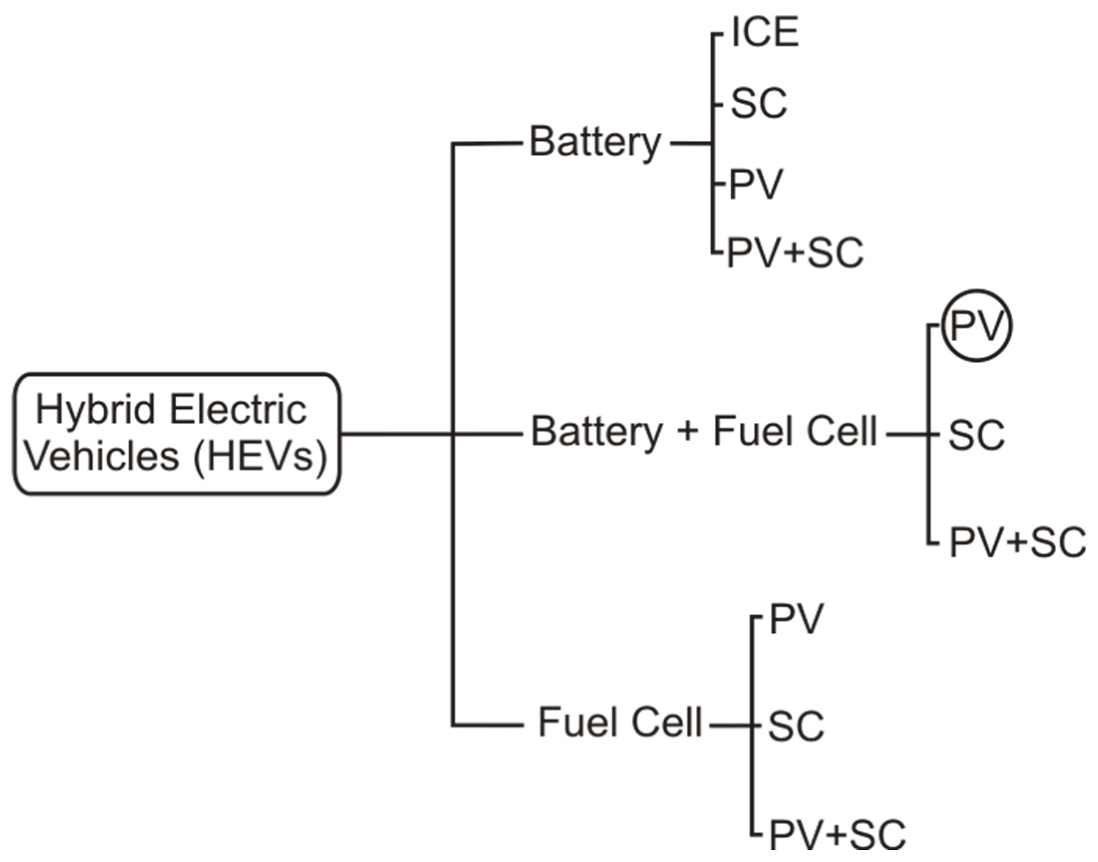
Figure 2.
Topology of the hybrid electric vehicle prototype.
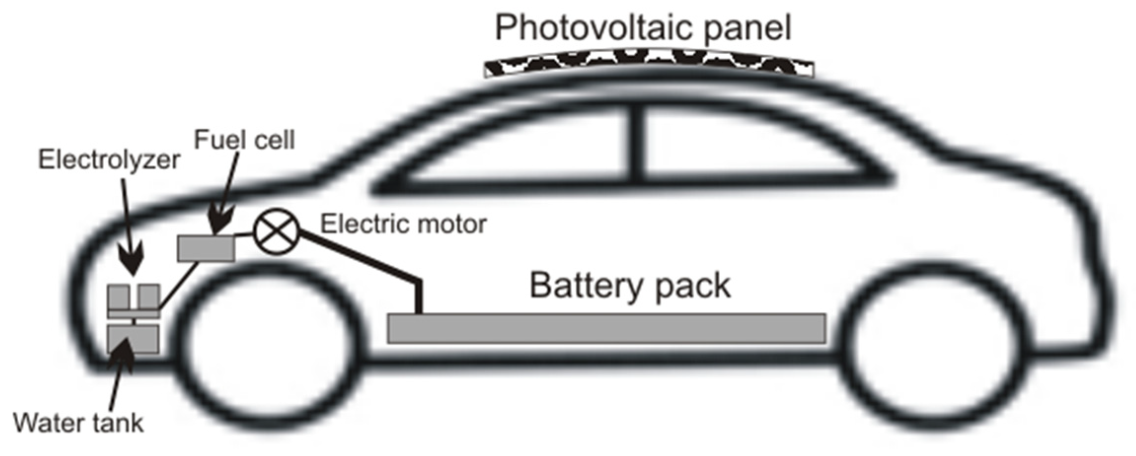
Figure 3.
Curve solar photovoltaic panel for vehicle rooftop mounting.

Figure 4.
Evolution of PV energy generation.
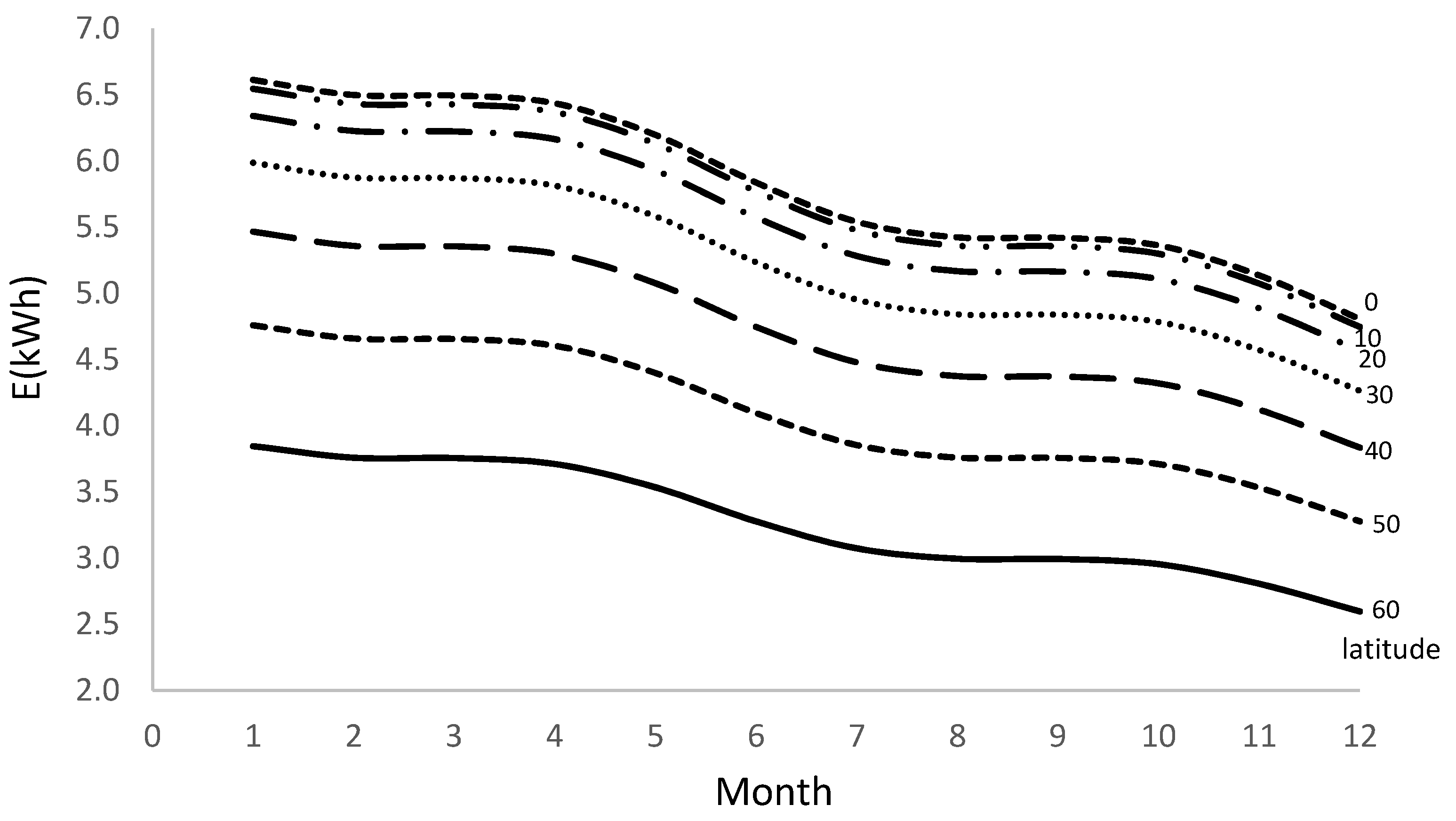
Figure 5.
Flowchart of control system operation.
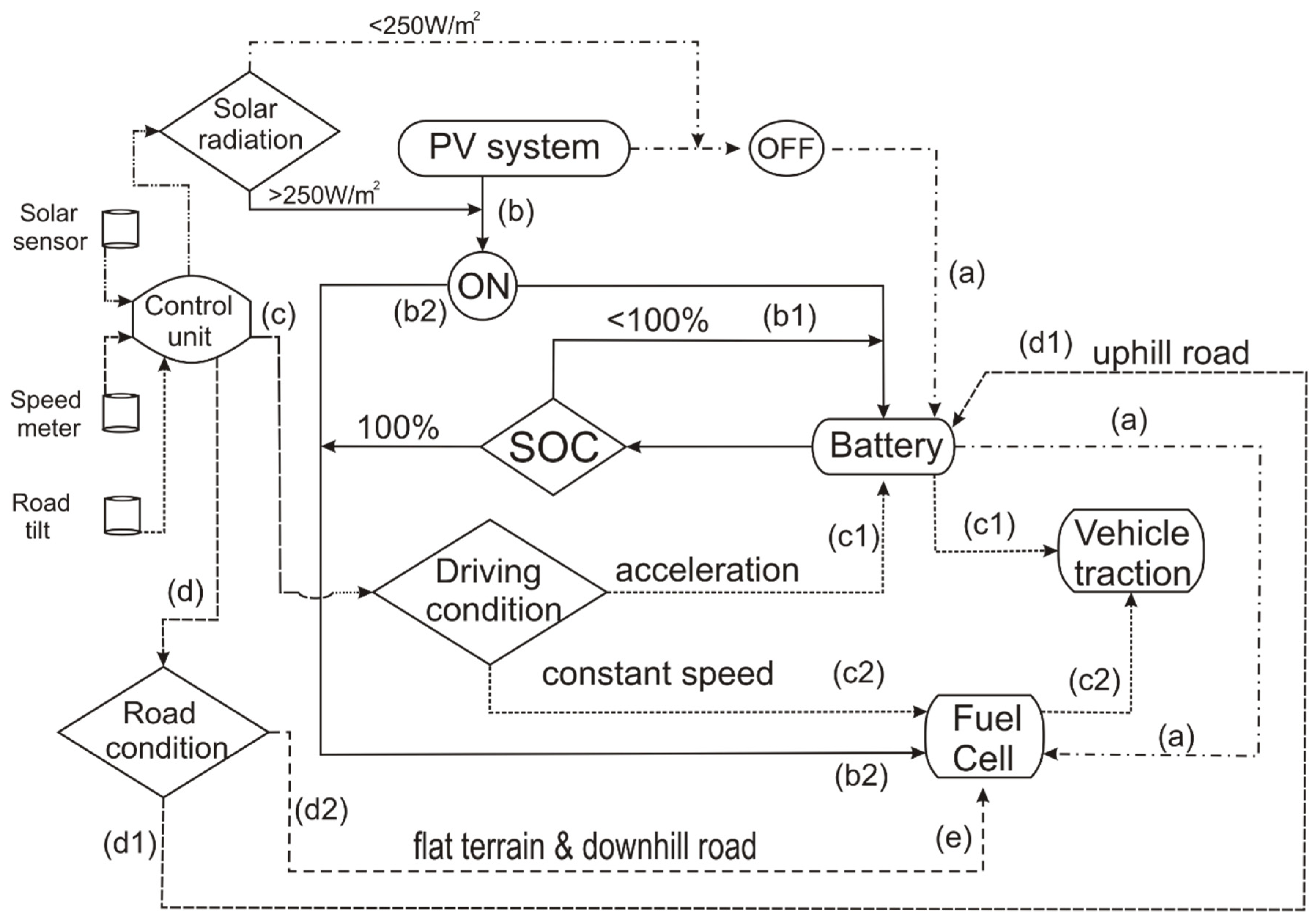

Table 1.
Hybrid system daily power and energy characteristics.
| Photovoltaic System | Battery | Fuel Cell | |||
|---|---|---|---|---|---|
| Power (kW) | Energy (kWh) | Power (kW) | Energy (kWh) | Power (kW) | Energy (kWh) |
| 1.152 | 5.2 | 92.3 | 6.27 | 15.5 | 14.27 |
Table 2.
Driving range for different electric vehicle topology (km).
| Topology | Standard Energy Consumption Rate | Reduced Energy Consumption Rate | ||
|---|---|---|---|---|
| Maximum | Average | Minimum | ||
| Battery only | 317.1 | 275.7 | 248.1 | 324.4 |
| Fuel cell only | 640.0 | 520.0 | 480.0 | 528.7 |
| Battery + Fuel cell | n.a. | n.a. | n.a. | 728.5 |
Table 3.
Driving range gain for the hybrid prototype (all values in km).
| Energy consumption rate | |||
|---|---|---|---|
| Optimum | Average | Minimum | |
| Prototype | 728.5 | 728.5 | 728.5 |
| Simulated | 601.3 | 490.7 | 452.2 |
| Gain | 127.2 | 237.8 | 276.3 |
Table 4.
Comparative cost of single and hybrid power system for electric vehicles.
| Cost | ||
|---|---|---|
| System | USD | € |
| Lithium battery | 7170.0 | 6750.8 |
| Fuel Cell | 9737.5 | 9168.1 |
| Hybrid | 8311.8 | 7825.8 |
Table 5.
Comparative global cost of single and hybrid power system for electric vehicles for the battery lifespan.
Table 5.
Comparative global cost of single and hybrid power system for electric vehicles for the battery lifespan.
| Cost | ||
|---|---|---|
| System | USD | € |
| Lithium battery | 8526.4 | 8984.7 |
| Hybrid | 8311.8 | 7825.8 |
Disclaimer/Publisher’s Note: The statements, opinions and data contained in all publications are solely those of the individual author(s) and contributor(s) and not of MDPI and/or the editor(s). MDPI and/or the editor(s) disclaim responsibility for any injury to people or property resulting from any ideas, methods, instructions or products referred to in the content. |
© 2024 by the authors. Licensee MDPI, Basel, Switzerland. This article is an open access article distributed under the terms and conditions of the Creative Commons Attribution (CC BY) license (http://creativecommons.org/licenses/by/4.0/).
Copyright: This open access article is published under a Creative Commons CC BY 4.0 license, which permit the free download, distribution, and reuse, provided that the author and preprint are cited in any reuse.


