Submitted:
29 March 2024
Posted:
29 March 2024
Read the latest preprint version here
Abstract
An analysis of form and size of the fatigue wear of gear wheel top layer of the prototype oil pump (type 3PW-BPF-24) is presented in the publication. The object of research was subject to endurance tests, so called labour resource test. During this test the pump was loaded in cycles with maximal working pressure. Additionally, continuous monitoring tests of exploitational and environmental parameters were conducted. After a completion of the endurance test the noticed superficial defects due to a phenomenon of the top layer fatigue and previously applied thermochemical treatment were measured and described. The work was finished with an analysis of obtained results and conclusions concerning a selection optimization of the thermal treatment parameters. Taking into consideration the presented results (suggestions) in the technology of improving strength prop-erties of gear wheels (of this type oil pumps) may render it possible to obtain an appropriate fa-tigue endurance of the top layer, i.e. a minimization of observed superficial defects.
Keywords:
analysis of surface
; pitting
; thermochemical treatment
; residual austenite
; gear pump
1. Introduction
Gear wheels, as the basic components of the majority of drive transmissions systems, a transmission of rotary motion or a transport of medium (e.g. oil) must appropriately meet a series of rigorous technical requirements. A contact between the teeth of wheels (pinions), mutually collaborating, is regarded to be, in the domain of tribology, one of the most complicated cases of contact interaction. Taking into consideration all the factors aimed at an improvement of life, efficiency and reliability of gears and gear pumps in the designing and manufacturing phase does not seem to be sufficient yet. An essential and really equivalent factor also includes a correct exploitation of this type subassemblies, taking into consideration new diagnostic and control methods. For example an application of units in multi-source systems increases the endurance of components because the control is carried out in an automatic way without a direct operator’s participation. The life of subassemblies may be even threefold longer in this case [1,2]. Apart from technical requirements, it is also essential to consider other factors having an impact on life, efficiency and reliability of gear pumps. The designing process of gear wheel must take into account an appropriate geometry of teeth, a proper profile, dimensional tolerances and a selection of materials. An accuracy of manufacture and a precise fitting of elements are crucial for ensuring an optimum operation of the system.
A correct lubrication of collaborating gear wheels has a key significance for a reduction of friction, wear and failures [3,4]. A regular maintenance, an exchange of oil and monitoring of lubrication quality are important activities in maintaining an appropriate reliability and endurance. In particular a lubrication plays an essential role in the case of using working liquids being an oil-in-water emulsions [5] or an operation of pump in the conditions of thermal shock [6].
The state-of-the-art diagnostic methods such as an analysis of vibrations, thermographics or spectrometry enable to monitor a condition of a gear wheel during its exploitation. They enable to detect early signs of wear, damages or irregularities which renders it possible to undertake appropriate corrective measures before an occurrence of more serious failures. It is possible to find in literature many novel elaborations and suggestions, concerning gear wheels and gear pumps. Tests of new materials, technologies of manufacture, an improvement of teeth geometry and an optimization of lubrication are aimed at increasing endurance, efficiency and reliability of these elements.
In the work [7] the authors presented research results oriented onto testing of efficiency and reliability of different techniques for monitoring damages of gears. Test cases with different kinds of teeth damages in the gear were used. In the result of tests it was stated that the beta kurtosis was a reliable diagnostic technique and a wavelet transform was useful for a visualization of inspection, in particular while using residue signals. In the work [8] the authors concentrated on an identification of future testing possibilities in the scope of diagnostics of damages, using a quality analysis of the tree of damages. In turn, in the work [9] a simple monitoring method of the condition of gears, operated in impulse environments, was presented. The method of synchronous median has turned out to be more resistant to a presence of impulse components of signal which makes it more reliable in an estimation of the state of individual components of the machine. The tests were based both on numerical as well as experimental data. Besides, there are other publications, in which selected diagnostic methods, concerning an assessment of gear wheels condition - a detection of damages during an operation of a pump or of a gear - without any disassembly [10,11,12,13], are presented.
The damaged gear wheels are subject to macroscopic and microscopic tests to obtain even better results. The assessment methods of gear wheels wear after their disassembly, with use of microscopes such as microscopes of focal differentiation made by the Alicona Company [17,18], can deliver detailed information on state of surfaces of gear wheels and the degree of their wear.
During a wear assessment of gear wheels with use of microscopes, specialistic software and high resolution of images a precise geometric measurement of external and internal dimensions of teeth, a profile of tooth, pitches and tolerances [19,20] is carried out. Additionally, the methods of finite elements analysis (FEM) e.g. the ANSYS software enabling to conduct a virtual analysis of load and wear of gear teeth based on a numerical method, are also used. These methods are particularly useful for forecasting a behavior of gear wheels in different operational conditions, an optimization of the project and a diagnosis of problems related to the strength and wear [21,22,23].
In this work the tests of form and size of fatigue wear of the top layer of oil gear pump wheel (3PW-BPF-24) are presented. The object of tests was operated during a determined number of hours at strictly controlled operational and environmental parameters. A microscope of focal differentiation by Alicona was used for an identification, measurement and description of noticed superficial defects, which resulted from the fatigue process of the top layer and an earlier thermochemical treatment.
2. Macroscopic Tests of Gear Pumps
Macroscopic tests, concerning the fatigue wear of gear pumps concentrate on an analysis and assessment of structural fatigue, which may lead to a failure in this type of device. Those tests include a detailed analysis of the material fatigue, geometric distortions and other factors affecting the strength of gear pumps. Within the framework of those tests, the methods of observations and measurements, which enable an assessment of the fatigue wear on the macroscopic level, are used most often. This process can incorporate an analysis of cracks, microcracks, changes of shape and structural damages on the surfaces of teeth, pump frame, shafts and other elements [24,25,26]. Macroscopic tests enable an assessment of gear pumps condition, an identification of potential problem areas and an assessment of the remaining life and reliability of these devices. Based on macroscopic observations, it also possible to elaborate a strategy of maintenance and repair of gear pumps to minimize a risk of failure and to extend their life. The examples of work concerning macroscopic tests of fatigue wear in gear pumps are e.g. [27,28,29]. In the work [27] experimental tests of macroscopic fatigue wear in gear pumps, concentrating on an analysis of failure and prevention have been conducted. In the work [28] its authors carried out a macroscopic observation and an analysis of a fatigue damage in gear pumps at different operational conditions. In turn, in the work [29] the test is concentrated on macroscopic characteristics of gear pumps failures in the conditions of high speed and big load. In these tests an essential aspect includes an analysis of so called pitting, i.e. a generation of losses on teeth surfaces of gear wheels. Pitting is one of the main mechanisms of fatigue damage in gear pumps and that is why this phenomenon has a key significance in macroscopic tests concerning an assessment of fatigue wear.
2.1. A Consideration of Pitting in a Fatigue Wear Assessment of Gear Wheel Top Layer
The basic phenomenon of top layer wear of gear wheels operated in the medium such as hydraulic oil, mainly includes pitting. It is a kind of damage which occurs on surfaces of teeth and it is characterized by a generation of micro and macrocracks and electric discharges in the result of high contact stresses.
Pitting can lead to a gradual deterioration of teeth surface quality, causing an erosion and flaking of material. This phenomenon is particularly dangerous because it can lead to serious damages of gear wheels and in consequence to a failure of the whole machine. Tests are concentrated on an identification, measurement and description of pitting to analyze its impact on the output and life of gear pumps in a better way.
Over the years from 2010 to 2022 many interesting tests, concerning pitting and micro-pitting in the context of gear wheels, were concluded. The researchers tried to go deeply into mechanisms of generating these damages and to identify factors which affect them. One of such tests was an elaboration [30], in which the authors concentrated on a generation and evolution of pitting in gear wheels. Analyzing different factors, which affect a generation of this damage, they suggested strategies of minimizing the pitting, aimed act an extension of a gear-box.
Another analysis, which deserves an attention, is presented in [31]. The tests were concentrated on a behaviour of micro-pitting in relation to different conditions of lubrication in gear wheels. Through an analysis of identification and propagation mechanisms of micro-pitting and assessment of lubrication impact on this process, the researchers recognized the processes occurring during this damage. In the work [32] the authors concentrated on an analysis of pitting in worm-and-sector steering gears. Using a semi-terministic method, the researchers attempted to understand processes of damage and to assess an impact of different factors on pitting in the gears of this type.
The tests, conducted by [33] were concentrated on an impact of micro-pitting on fatigue life of teeth surfaces in gears. Using a numerical and experimental analysis, the researchers assessed an impact of micro-pitting on life of gears. All these tests have an essential significance for understanding pitting and micro-pitting in the context of gear wheels. They present different aspects of those damages such as mechanisms of generation, an impact of environmental factors and lubrication and also strategies of minimization and assessment of the impact on gear life.
Besides, operational properties of machine elements such as gear wheels others mainly depend on an application of appropriate manufacturing technologies. In particular, due to life of steel elements, subject to treatment, the heat treatment giving optimum useful properties [34,35] has an essential significance.
A key issue includes a presence of residual austenite in the top layer of gear wheels subject to heat treatment [36]. A significant number of research projects indicates that a presence of residual austenite, apart from a suitable limit value, reduces fatigue strength, hardness and abrasion resistance [37,38,39].
3. Characteristics of Test Object
The analysis results of fatigue wear form and size of the driven wheel of the prototype, high pressure gear pump (type: 3PW-BPF-24) are presented in this elaboration. The pump was subject to an endurance test (so called labour resource test) [40]. The endurance test is a part of a compulsory set of tests to be performed before introducing the pump to the mass production. The test, according to the accepted standard, requires a million cycles of loading. The period of one cycle is 2s, during which the pump is loaded with the rated pressure at the half-cycle and afterwards it is unloaded. The pump rotational speed (according to the project assumptions) is determined in the scope from 600 to 6000 rev/min. However, the rotational speed, at which the pump was tested, complies with the rated speed of 1500 rev/min. The pump operational medium was hydraulic oil HL68, having a wide application in medium loaded hydraulic drive and control systems. According to the producer’s catalogue card [41] the HL68 oil guarantees a good protection of surfaces of lubricated elements (density: 0.885 g/cm3 at 15°C, kinematic viscosity: 68 mm2/s at 40°C). During the test the oil temperature was maintained on the level of recommended rated value reaching 50°C. However, the maximum temperature limit of operation for this unit is 80°C. The object of tests worked 24 hours, day and night, at controlled rated operational and environmental parameters (i.e. appropriate rotational speed and constant temperature) till one million cycles of loading is reached (about 24 days). After endurance test the hydraulic characteristics for selected rotational speed n=800; 1000; 1500; 2000 rev/min were determined. The condition, enabling to approve of the pump design, according to the standard, includes a reduction of efficiency at any working pressure by a value not exceeding 8% in relation to the characteristics obtained directly after a factory run in. After a completion of the labour resource test the experimental unit was disassembled and each of its components was subject to detailed visual inspection and an analysis oriented onto a determination of the wear degree.
A general view of the analyzed pinion after a completion of the labour resource test is presented in Figure 1.
The project assumptions required a manufacture of the pinion, subject to tests, of steel for carburization of the 17HNM grade (acc. to out-of-date standard PN-89/H-84030-02) or 17NiCrMo6-4 acc. to PN-EN ISO 683-2:2022-07) and reaching the following properties due to applying thermochemical treatment:
- the thickness of carburized layer (after mechanical working): 0.5-0.9 mm (marked in Figure 2);
- the core hardness: 29-42 HRC;
- the hardness of top layer of working surfaces: 60-64 HRC.
The values given above were not fully reached due to high contents of residual austenite (which is described in a further part of this elaboration).
4. Results of Macroscopic Tests
Macroscopic tests of gear wheel external surfaces were made with naked eye and with use of stereoscopic microscope SMT-800 [42].
On the external surface of teeth both sides, the traces of exploitation in a form of chippings and of working surfaces wear – Figure 1 [42] were seen.
After cutting off a specimen perpendicularly to the tooth generating line, after its regrinding and pickling with use of the reagent Mi11Fe acc. to PN-H-04503:1961, some changes of macrostructure resulting from an application of the surface thermochemical treatment to the depth of about 0.55mm, shown in Figure 2 [42], were noticed. Additionally, the macroscopic analysis of external surfaces of the gear wheel also showed a presence of micropitting, which is a minute kind of superficial damage. Micropitting is caused by contact stress and cyclic loading which leads to a generation of microdamages on the surface of teeth. An occurrence of micropitting may indicate inappropriate operational of constructional parameters of the gear wheel.
5. Results of Microscopic Tests
Specimens for microscopic tests were cut off perpendicularly to the tooth generating line. Microscopic tests were conducted at magnification in the scope from 100x to 1000x in the non-pickling condition and after pickling with the reagent Mi1Fe according to the out-of-date standard PN-H-04503:1961. The metallographic microscope Epiphot 200, coupled with a digital film camera CCD Nikon, was used. The photographic documentation (of characteristic structures), related to the scope of work [42], is only and exclusively presented in the elaboration.
In the non-pickling condition an occurrence of a minor amount of non-metallic inclusions, mainly in a form of oxides spaced pointwise, was noticed. In the close-to-the-surface layer no internal oxidation zone was spotted [42].
After pickling with the reagent Mi1Fe a structure typical for carbonized, heat treated objects was seen. A determination of a conventional depth of hardening after carbonization was carried out by a measurement of hardness at the cross-section along the normal to the carbonized surface, in the direction from the surface to the inside of material according to the standard PN-EN ISO 18203:2022-09. The measurements were taken with use of the Vickers method in the conditions according to PN-EN ISO 6507-1:2018-05. The Zwick 321 hardness tester, the load of 1 kG (9.807 N) acting within the time of 15 s, was applied. An average core hardness from five measurements , made with use of the Vickers method, is 445 +/-3.25HV1 [42].
The depth of the tooth carbonized zone from side A is about 593 μm. An occurrence of about 30% residual austenite and then low-temperature tempered, fine acicular martensite of gradually decreasing carbon contents were detected – Figure 3. A cracked, strongly deformed layer of the thickness about 9 μm was seen on the tooth surface - Figure 4 [42].
The depth of the tooth carbonized zone from the B side is about 542 μm. In the close-to-the-surface zone from the B side to the depth of about 43.29 μm an occurrence of about 30% residual austenite and then low-temperature tempered, fine acicular martensite of gradually decreasing carbon contents were seen - Figure 5. A cracked, strongly deformed layer of the thickness about 7 μm was detected on the tooth surface - Figure 6 [42].
A structure of low carbon martensite after heat treatment typical for steels for carbonization was seen in the specimen core.
6. Analysis of the Material Chemical Composition
An analysis of the chemical composition of the pinion material was performed with the use of the spectral method, applying the PMI Master Pro spectrometer made by the Oxford Instruments Company.The results of the chemical composition of the specimen material are presented in Table 1. The obtained values were listed and compared with the chemical composition of the 17HNM steel acc. to the out-of-date standard PN-89/H-84030-02.
In the conducted analysis of the chemical composition, with use of the spectral method, it can be stated that in the scope of analyzed elements the material of the specimen, subject to tests, suits best the steel for carbonizing of the grade 17HNM acc. to the out-of-date standard PN-89/H8430-02 but it has no direct equivalent in the group of alloy, machine steels for carbonizing acc. to the standard PN-EN ISO 683-3:2022-07. An exact determination of the steel grade subject to tests, acc. to the standards, compulsory at present, requires an additional series of strength tests [42]. Additionally, the results of the chemical composition analysis indicate a presence possibility of other elements which can have an impact on the material properties. Such tests will enable an assessment of strength, hardness and other essential mechanical parameters which are of key significance for a correct identification of the material and its useful properties.
7. Methodology of Test
The Alicona InfiniteFocus G4 microscope of focal differentiation, which is a universal, precise and quick optical device for a measurement of the profile geometry, roughness and topography of the surface 3D, was used for an assessment of the kind and size of the top layer wear - Figure 7.
Scans of individual areas of pitting breaches were realized (in relation to the need) with objectives in the 5x or 10x magnification. During digitalizing a polarization diaphragm, which is in particular dedicated to strongly reflexive specimen was used (it was a necessity in the case of applying the Focus-Variation technology). An analysis of the surface topography 3D was carried out according to the recommendations PN-EN ISO 25178-600:2019-05 Standard.
Additionally, during the microscopic analysis with use of the microscope of focal differentiation Alicona InfiniteFocus G4, advanced algorithms of image processing, enabling an identification and measurement of micro - pitting depth, were applied. Due to that it was possible to obtain detailed information concerning the depth and dimensions of these defects which is essential for an assessment of their impact on the strength and functionality of a gear wheel.
8. Wear Assessment of Top Layer Working Surfaces of the Pinion
In the result of taking superficial scans 3D superficial fatigue damages (characterized by breaches of oval shapes and sharp edges, inclined perpendicularly to the surface of the teeth under analysis) - Figure 8, were diagnosed.
The observed breaches, generated in the result of the material chipping, have different dimensions, rough bottom and they occur locally or an a much smaller scale but on a bigger tooth surface (micropitting) - in particular below the pitch diameter of pinion. A linear arrangement of described defects was observed in some places - Figure 9.
An advancing chipping of the material particles, which is presented in Figure 9 can lead, in extreme conditions, to a reduction of the teeth working surface to a degree which will make a further transmission of loads (in the case of gears) impossible. In some situations teeth of carbonized wheels can change their shape to the degree leading to their significant wear or even fracture in the result of pitting. Carbonized and hardened teeth of wheels, which were subject to pitting in the area of the tooth root connected with a significant wear, are vulnerable to fracture. The reason is an initiation and a development of fatigue cracks in the pits generated where the crumbled away material was. A significant noise accompanies an operation of gear wheels with considerable pitting [43].
A surface increase of pitting cavities is caused very often by their mutual connecting. In Figure 10 and Figure 11 the limiting state before a connection of two fatigue breaches is presented.
The main reason of generating this type of breaches includes exceeding of limiting contact stresses of the teeth collaborating surfaces. The degree of tolerating this kind of defects (their number, size and arrangements) depends mainly on the application area. In this case (at an assumption of the forecasted pump life due to a degradation development of the top layer of collaborating teeth), it does not have any big significance. Pitting breaches in the scope of dimensions 0.1-1.5 mm (Figure 8) and even to 2.5 mm (Figure 9) do not exclude the pinion from its further (but temporary) exploitation. It should be borne in mind that correct filtration should be ensured. In this case a high pressure filter of exact purification should be installed directly after the pump to prevent against a failure of valves and receivers situated in the hydraulic line between the pump and the tank, caused by solid impurities.
Additionally, it should be taken into an account that a breach of 1 mm dia. close to the fillet of the tooth heat treated or superficially hardened, may begin a crack, which can finally lead to a tooth break; and that is why in some cases this kind of breach should be treated as inadmissible (e.g. in air applications) [43].
Destructive pitting develops naturally from non - destructive pitting, micropitting and that one in turn from a dull finish of surface and imperfections in the top layer of collaborating teeth. An essential issue also concerns a characteristic of chipping (Figure 8, Figure 9, Figure 10, Figure 11 and Figure 12) as well as a relationship between its depth and thickness of the top layer, subject to heat treatment, thermochemical treatment. The present measurement technologies (optical metrology) enable to check a real depth of this type defects.
To determine the essence of top layer wear of the pinion selected working surfaces under testing, a short geometric analysis of individual chippings was performed. In Table 2 basic measurement values, characterizing geometries of defects, are presented, i.e. maximum depths of pitting chippings are compared in relation to the changes in the macrostructure resulting from the applied thermochemical treatment.
In the cases under analysis the defect depth of the top layer did not exceed the depth of layer subject to thermochemical treatment. A location of all the chippings is enclosed in the scope of the zone, having the structure of law-temperature tempering, fine-acicular martensite of comparatively decreasing carbon contents. The measurement data from Table 2 are graphically presented in Figure 13.
9. Conclusions
Based on the taken 3D scans (defining the geometry of defects) it was stated that the conducted thermochemical treatment only partly met the project assumptions (in the sense of obtaining appropriate changes in the macrostructure inside the material). Unfortunately, a high content (up to 30%) of residual austenite in the volume of hardened surface enables to formulate a hypothetical conclusion concerning non-optimum parameters of a thermochemical process in relation to the chemical composition of the pinion under analysis.
An occurrence of residual austenite causes a reduction of the tooth surface hardness, an initiation of brittle fractures, a rapid reduction of fatigue strength and an increase of brittleness, in particular it can indicate a trend of generating fractures of the superficial layer during an exploitation [42].
Additionally, in the result of conducted analysis of chemical composition with use of spectral method, it can be stated that in the scope of the elements under analysis the material of the specimen, subject to tests, does not have its direct equivalent in the group of alloy, machine steels for carbonization according to the standard PN-EN ISO 683:2022-07. An application of steel grade, dedicated by the standards in power, enables to avoid a presence of other elements, which can affect properties of the material. A maintenance of a correct chemical composition will ensure required strength, hardness and other mechanical parameters which play a key role in ensuring correct useful properties.
Besides, to extend life of gear wheels, pinions their heat treatment should be selected properly. In the case of heavily loaded gear wheels it is recommended to use sub-zero treatment enabling a very efficient minimization of residual austenite contents and thus an improvement of hardness and a dimensional stabilization.
Additional information concerning recommendations and advantages resulting from heat treatment is as follows:
- the microstructure of the specimen, after the present heat treatment, subject to tests, indicates a partial meeting of project assumptions, but with a presence of residual austenite;
- a high content of residual austenite in the hardened surface volume suggests non-optimum parameters of heat treatment process in relation to the chemical composition of pinion subject to tests.
- Advantages resulting from heat treatment:
- a life extension of gear wheel parts through a minimization of residual austenite contents;
- an improvement of tooth surface hardness and dimensional stabilization;
- a reduction of initiations of brittle fractures, an improvement of fatigue strength and a reduction of brittleness;
- a protection against a generation of fractures in the top layer during an exploitation.
In relation to the information given above, it is recommended to apply additional heat treatment, in a form of sub-zero treatment which will enable an efficient minimization of the residual austenite contents, an improvement of hardness and a dimensional stabilization which will contribute towards an extension of the pinion life and an improvement of its useful properties.
Author Contributions
Conceptualization, R.Ł., P.O. and W.D.; methodology, A.D., R.Ł. and W.D.; software, M.K. and P.O.; validation, A.D., R.Ł. and M.K.; formal analysis, R.Ł. and P.O.; investigation, W.D.; resources, P.O., A.D. and M.K.; data curation, P.O. and W.D.; writing—original draft preparation, R.Ł., A.D.; writing—review and editing, P.O., W.D. and M.K.; visualization, R.Ł. and A.D.; supervision, W.D. All authors have read and agreed to the published version of the manuscript.
Funding
This research received no external funding.
Data Availability Statement
Not applicable.
Conflicts of Interest
The authors declare no conflict of interest.
References
- Kędzia, K. A method of determining optimal parameters for the secondary energy source of a multisource hydrostatic drive system in machines working in closed spaces. Energies 2022, 15(14), 5132. [Google Scholar] [CrossRef]
- Zubair, A. , Kędzia, K., Abbass, M. Fractional-order PID controller (FOPID) based iterative learning control for a nonlinear boiler system. Energies 2023, 16(3), 1045. [Google Scholar] [CrossRef]
- Szkodo, M., Stanisławska, A., Śliwiński, P. On the Durability of the Hydraulic Satellite Motor Working Mechanism in Overload Condition. Advances in Materials Science, 16(1), March 2016. [CrossRef]
- Osiński, P. Wysokosprawnościowe pompy zębate. Wrocław: Oficyna Wydawnicza Politechniki Wrocławskiej, 2019.
- Śliwiński, P. The methodology of design of satellite working mechanism of positive displacement machine. Scientific Reports, 12, 2022, 13685. [CrossRef]
- Jasinski, R. Analysis of the heating process of hydraulic motors during start-up in thermal shock conditions. Energies, 15(55), 2022. [CrossRef]
- Wang, G., Ismail, F., Golnaraghi, M.F. Assessment of gear damage monitoring techniques using vibration measurements. Mechanical Systems and Signal Processing, 15(5), 2001, 905-922. ISSN 0888-3270. [CrossRef]
- García Márquez, F.P., Pinar Pérez, J.M., Pliego Marugán, A., Papaelias, M. Identification of critical components of wind turbines using FTA over time. Renewable Energy, 87(Part 2), 2016, 869-883. ISSN 0960-1481. [CrossRef]
- Schmidt, S., Zimroz, R., Chaari, F., Heyns, P.S., Haddar, M.A. Simple Condition Monitoring Method for Gearboxes Operating in Impulsive Environments. Sensors, 20, 2020, 2115. [CrossRef]
- Zimroz, R., Bartelmus, W., Barszcz, T. Advanced signal processing methods for fault diagnosis of gears. MDPI AG, 2016. [CrossRef]
- Antoniadis, I., Panagiotopoulos, P., Ampatzidis, T. A review of condition monitoring techniques for gearboxes. Reliability Engineering & System Safety, 202, 2020, 107134. [CrossRef]
- Liang, Y., Zuo, M.J. Gear fault diagnosis and prognosis: A review of vibration-based methods. Mechanism and Machine Theory, 78, 2014, 21-46. [CrossRef]
- Yilmaz, A., Demircioglu, O. Review of vibration-based condition monitoring and diagnostics of gears. Mechanical Systems and Signal Processing, 87, 2017, 556-576. [CrossRef]
- Seshadri, R., Ratna Kumar, P.V. Gearbox condition monitoring based on oil analysis: A review. Measurement, 104, 2017, 349-362. [CrossRef]
- Guo, H., Zhang, K., Wang, Z. A review on gear fault diagnosis using oil debris analysis. Measurement, 132, 2018, 395-404. [CrossRef]
- Stearns, M., Mathew, J., Nair, A.S. Gearbox condition monitoring and fault diagnosis using oil debris analysis. Journal of Sound and Vibration, 333(25), 2014, 7046-7059. [CrossRef]
- Ahmed, Y.S., Fox-Rabinovich, G., Paiva, J.M., Wagg, T., Veldhuis, S.C. Effect of Built-Up Edge Formation during Stable State of Wear in AISI 304 Stainless Steel on Machining Performance and Surface Integrity of the Machined Part. Materials, 10, 2017, 1230. [CrossRef]
- Bello, S.M., Verveniotou, E., Cornish, L., Parfitt, S.A. 3-dimensional microscope analysis of bone and tooth surface modifications: comparisons of fossil specimens and replicas. Scanning, 33, 2011, 316-324. [CrossRef]
- Evans, A.A., Macdonald, D. Using metrology in early prehistoric stone tool research: further work and a brief instrument comparison. Scanning, 33, 2011, 294-303. [CrossRef]
- Chang, H., Borghesani, P., Smith, W.A., Peng, Z. Application of surface replication combined with image analysis to investigate wear evolution on gear teeth - A case study. Wear, 430–431, 2019, 355-368. ISSN 0043-1648. [CrossRef]
- Chen, X., Cheng, G., Li, Y. Analysis of gear fatigue life based on the finite element method. Journal of Mechanical Engineering, 54(14), 2018, 45-51.
- Guo, Y., Peng, Z., Huang, T. Numerical simulation and analysis of the tooth contact stress of helical gears based on ANSYS. Proceedings of the Institution of Mechanical Engineers, Part C: Journal of Mechanical Engineering Science, 230(2), 2016, 180-192.
- Hojjati, M., Golafshani, A.A. A comprehensive study on the prediction of gear fatigue life using finite element analysis. Journal of Vibration Engineering & Technologies, 7(3), 2019, 309-320.
- Rong, Z., Sun, Z. Research on fatigue failure of gear pump based on macro observation. International Journal of Mechanical Sciences, 155, 2019, 136-144.
- Zou, X., Ma, Y., Zhou, L. Fatigue analysis and life prediction of gear pumps based on macroscopic observation. Journal of Mechanical Engineering Research and Developments, 41(2), 2018, 109-113.
- Zhang, J., Li, D., Huang, H. Experimental investigation of fatigue life for gear pumps based on macroscopic observation. International Journal of Mechanical Engineering and Applications, 4(6), 2016, 132-137.
- Li, Y., Liu, S., Wang, J. Experimental investigation on the macroscopic fatigue failure of gear pumps. Journal of Failure Analysis and Prevention, 18(5), 2018, 1167-1176.
- Zhang, L., Li, C., Sun, C. Macroscopic observation and analysis of fatigue failure in gear pumps under different working conditions. Tribology International, 116, 2017, 1-9.
- Wang, Y., Zhao, Q., Zheng, J. Investigation on macroscopic failure characteristics of gear pumps under high-speed and heavy-load conditions. Journal of Mechanical Engineering, 52(4), 2016, 107-112.
- Song, Y., Cheng, X., Zhang, X. Investigation on the formation and evolution mechanism of pitting in gears. Tribology International, 158, 2021, 106913.
- Gao, W., Wu, T., Zhu, Y. Investigation on micro-pitting initiation and propagation behavior in gears under different lubrication conditions. Journal of Tribology, 142(2), 2020, 021503.
- Zhang, J., Chen, L., Li, X. Investigation on the pitting failure of helical gears based on the semi-deterministic method. Engineering Failure Analysis, 105, 2019, 791-802.
- Liu, Q., Wang, Y., Guo, Y. A study on the impact of micro-pitting on the tooth surface fatigue life of gears. International Journal of Fatigue, 113, 2018, 69-77.
- Smith, W.R., Hashemi, J. Foundations of Materials Science and Engineering. 4th Edition. McGraw-Hill Education, 2006. ISBN 978-0073529240.
- Rajan, T.V., Sharma, C.P., Sharma, A. Heat Treatment: Principles and Techniques. New Age International, 2012. ISBN 978-8122430199.
- eleńkowski, J. Austenit szczątkowy w stalach węglowych i stopowych. Obróbkametalu, tom 1, 2015, 14-18, AWART MEDIA.
- Zhang, Y., Zhang, Z., Wang, H., Li, Q. Effect of retained austenite on the mechanical properties and wear resistance of bearing steel. Materials Science and Engineering: A, 711, 2018, 259-266.
- Luo, Q., Han, F., Song, L., Li, Y., Cao, J. Effects of retained austenite on fatigue properties of high strength gear steel. Materials Science and Engineering: A, 656, 2016, 223-229.
- Al-Helal, I.M., Al-Azzawi, A.H., Al-Tikrity, E.T. Effect of retained austenite on the mechanical properties of low-alloy steels. Journal of Materials Engineering and Performance, 23(9), 2014, 3265-3272.
- Osiński, P., Bury, P., Cieślicki, R., Rutański, J. Durability tests of prototype gear pumps with reduced flow ripple. Technical Transactions, 117(1), 2020, 1-8.
- Karta Charakterystyki Hydrol L-HL 68. Producent OrlenOIL, 2022. https://www.orlenoil.pl/PL/NaszaOferta/KartyCharakterystyki/Strony/KartyCharakterystyki.aspx.
- Dudziński, W. Ekspertyza dot. badań metalograficznych w celu określenia poprawności wykonania operacji nawęglania i hartowania koła zębatego. Politechnika Wrocławska, Wydział Mechaniczny, Katedra Materiałoznawstwa, Wytrzymałości i Spawalnictwa, Wrocław 2016.
- PN-M-88506:1991, Reduktory i motoreduktory ogólnego przeznaczenia - Uszkodzenia kół zębatych - Terminologia (wersja polska).
Figure 1.
General view of gear wheel [42].
Figure 1.
General view of gear wheel [42].
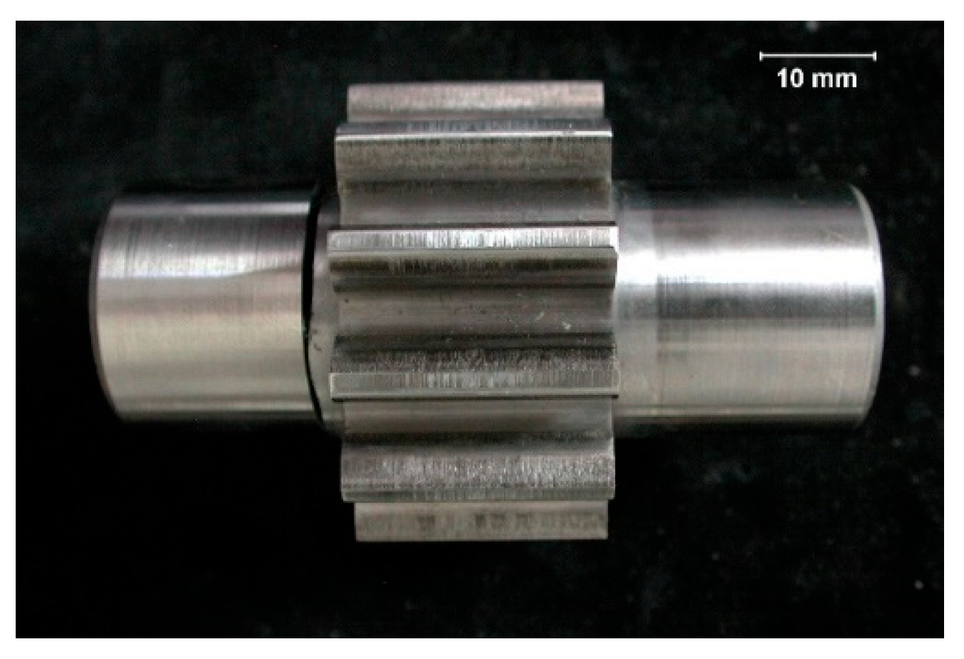
Figure 2.
Tooth cross-section (visible changes of macrostructure resulting from the applied thermochemical treatment) [42].
Figure 2.
Tooth cross-section (visible changes of macrostructure resulting from the applied thermochemical treatment) [42].
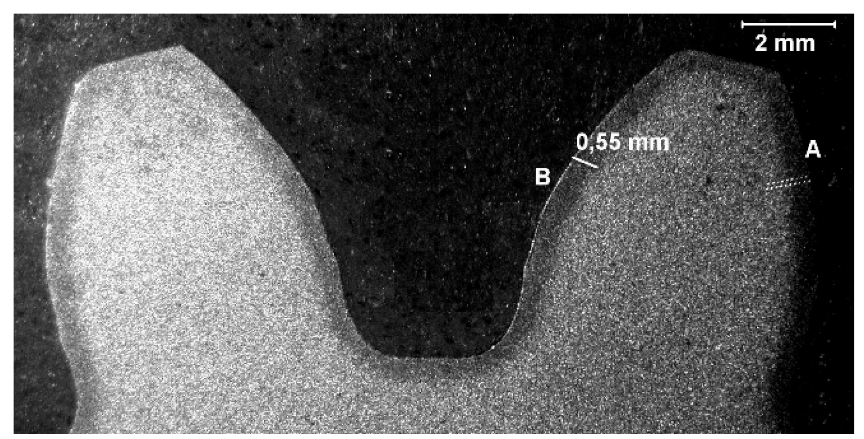
Figure 3.
View of carbonized and hardened layer on the specimen cross-section from the A side with indentations of hardness distribution measurements and the layer of residual austenite (light microscopy, Mi1Fe pickling) [42].
Figure 3.
View of carbonized and hardened layer on the specimen cross-section from the A side with indentations of hardness distribution measurements and the layer of residual austenite (light microscopy, Mi1Fe pickling) [42].
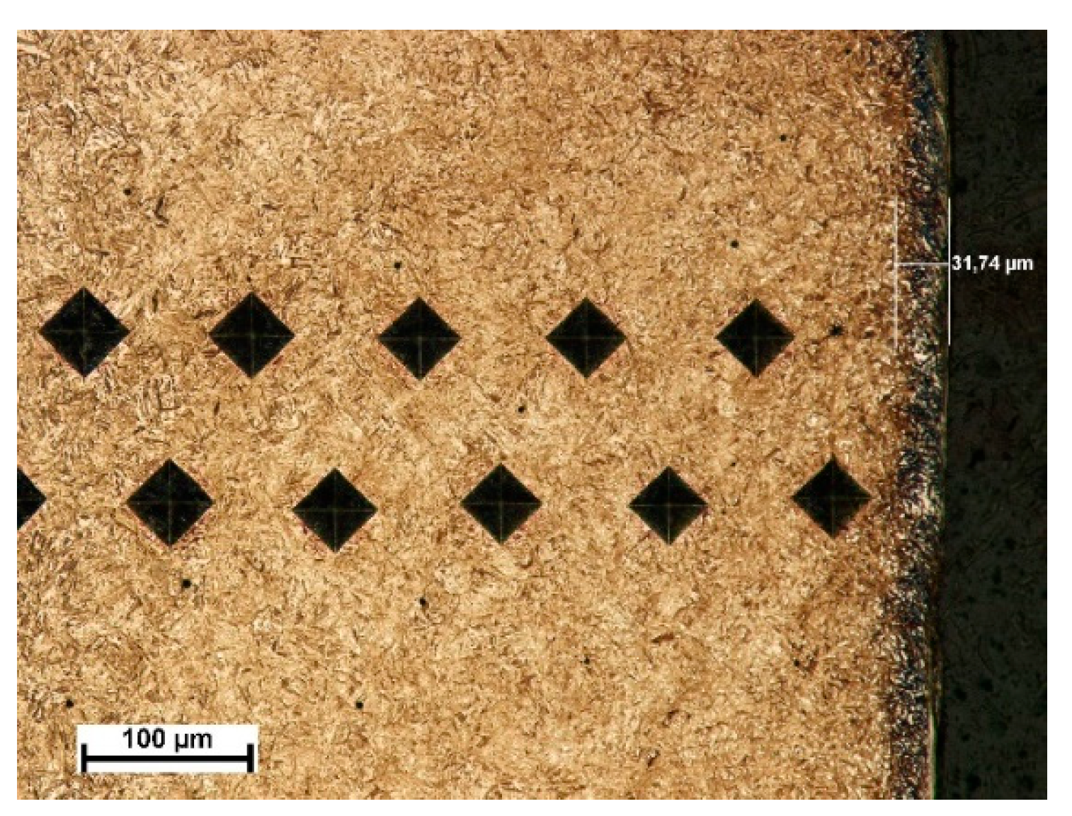
Figure 4.
View of carbonized and hardened layer on the cross-section of the specimen from the A side - martensite with residual austenite with strongly deformed and cracked layer of the thickness about 9 μm (light microscopy, Mi1Fe pickling) [42].
Figure 4.
View of carbonized and hardened layer on the cross-section of the specimen from the A side - martensite with residual austenite with strongly deformed and cracked layer of the thickness about 9 μm (light microscopy, Mi1Fe pickling) [42].
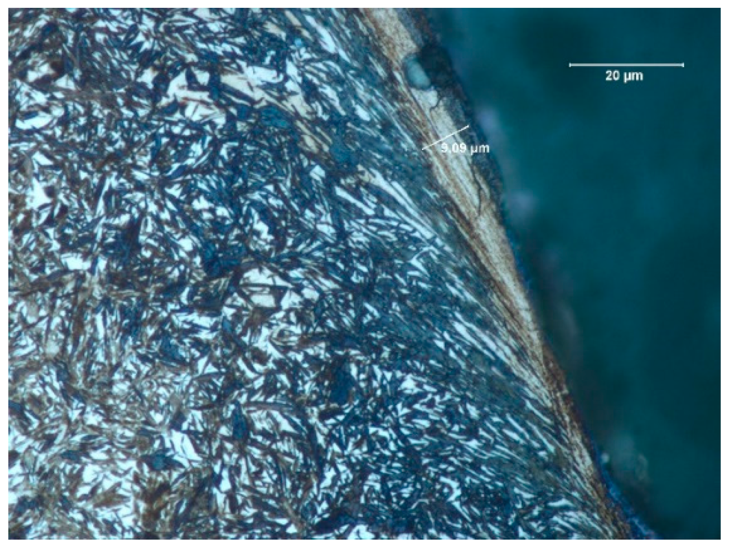
Figure 5.
View of carbonized and hardened layer on the specimen cross-section from the B side with indentions of the hardness distribution measurements and the layer of residual austenite (light microscopy, Mi1Fe pickling) [42].
Figure 5.
View of carbonized and hardened layer on the specimen cross-section from the B side with indentions of the hardness distribution measurements and the layer of residual austenite (light microscopy, Mi1Fe pickling) [42].
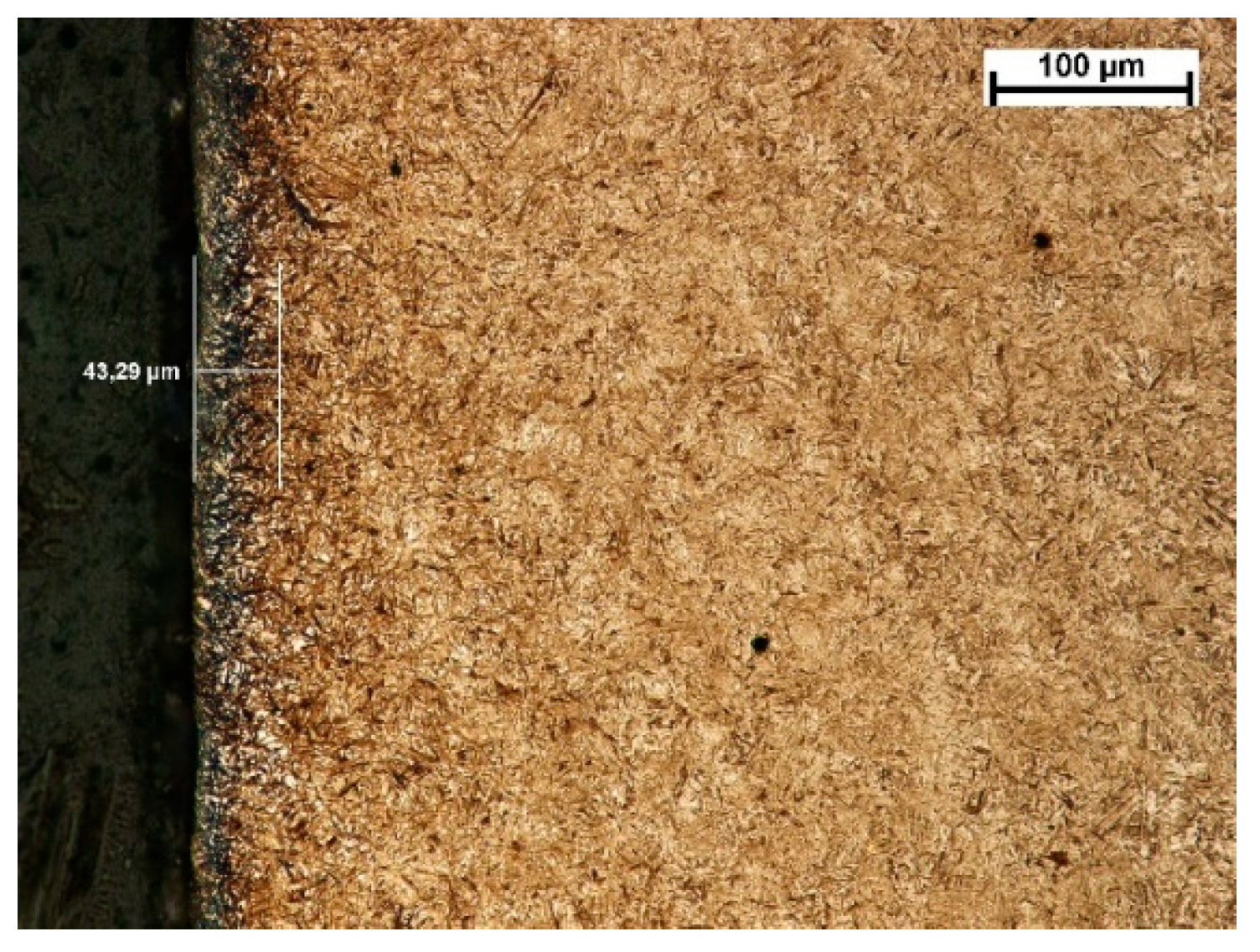
Figure 6.
View of carbonized and hardened layer on the specimen cross-section from the B side-martensite with residual austenite with strongly deformed and cracked layer of the thickness about 7.3 μm (light microscopy, Mi1Fe pickling) [42].
Figure 6.
View of carbonized and hardened layer on the specimen cross-section from the B side-martensite with residual austenite with strongly deformed and cracked layer of the thickness about 7.3 μm (light microscopy, Mi1Fe pickling) [42].
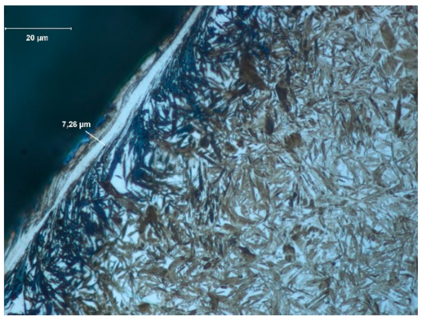
Figure 7.
Characteristics of the measurement rig (Alicona InfiniteFocus G4 microscope of focal differentiation).
Figure 7.
Characteristics of the measurement rig (Alicona InfiniteFocus G4 microscope of focal differentiation).
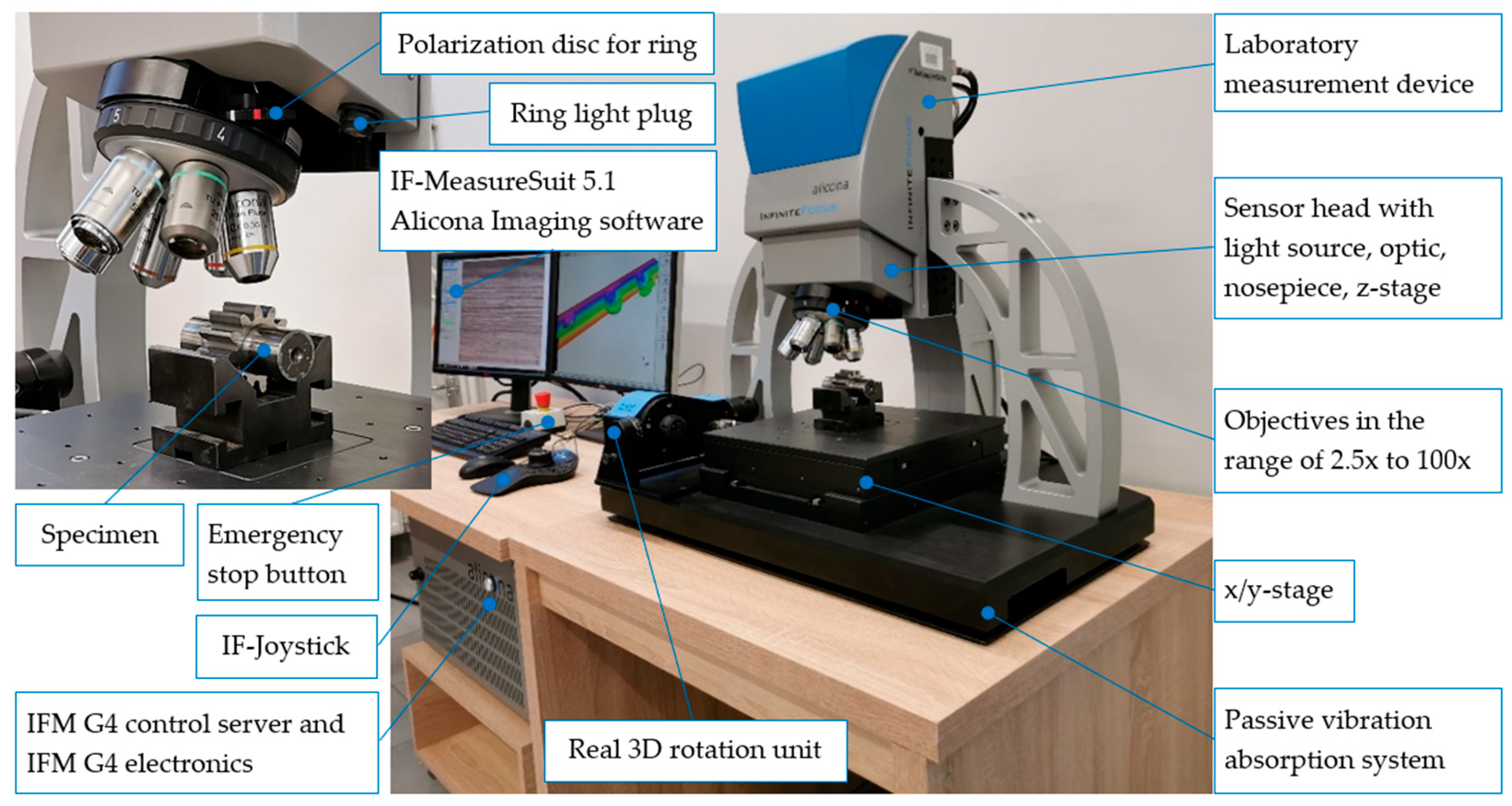
Figure 8.
Fatigue pits (pitting) on the tooth working surface - magnification 5x; a) photo simulation, b) profile curve, ----- - line of cross - section, □ - indication of breaches edges inclined to the surfaces, subject to analysis at the angle close to 90° on the cross-section.
Figure 8.
Fatigue pits (pitting) on the tooth working surface - magnification 5x; a) photo simulation, b) profile curve, ----- - line of cross - section, □ - indication of breaches edges inclined to the surfaces, subject to analysis at the angle close to 90° on the cross-section.
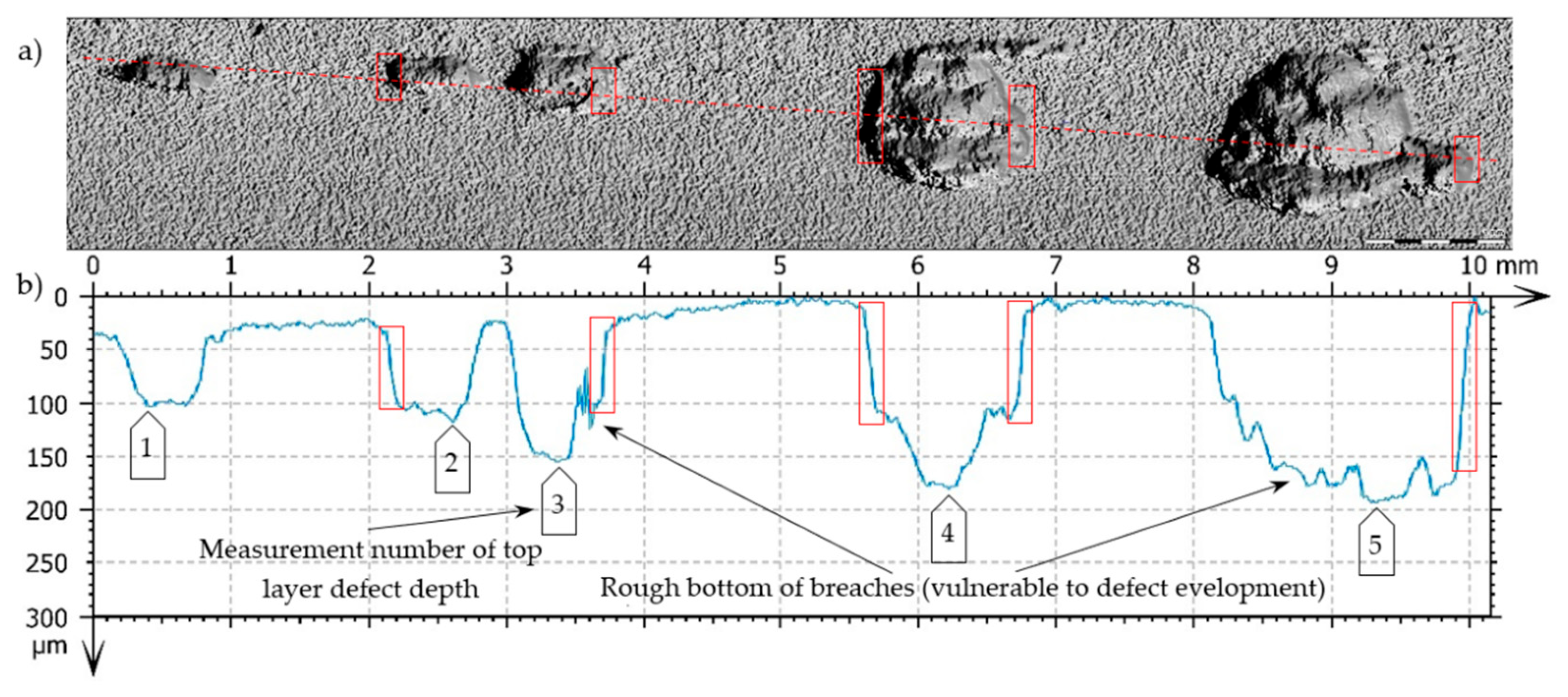
Figure 9.
Fatigue pit (pitting) on the tooth working surface - magnitude 5x. a) photo simulation, b) profile curve, c) and d) 3D superficial view - pseudocolour of surface with the depth visualization, -----, ----- - lines of cross-section.
Figure 9.
Fatigue pit (pitting) on the tooth working surface - magnitude 5x. a) photo simulation, b) profile curve, c) and d) 3D superficial view - pseudocolour of surface with the depth visualization, -----, ----- - lines of cross-section.
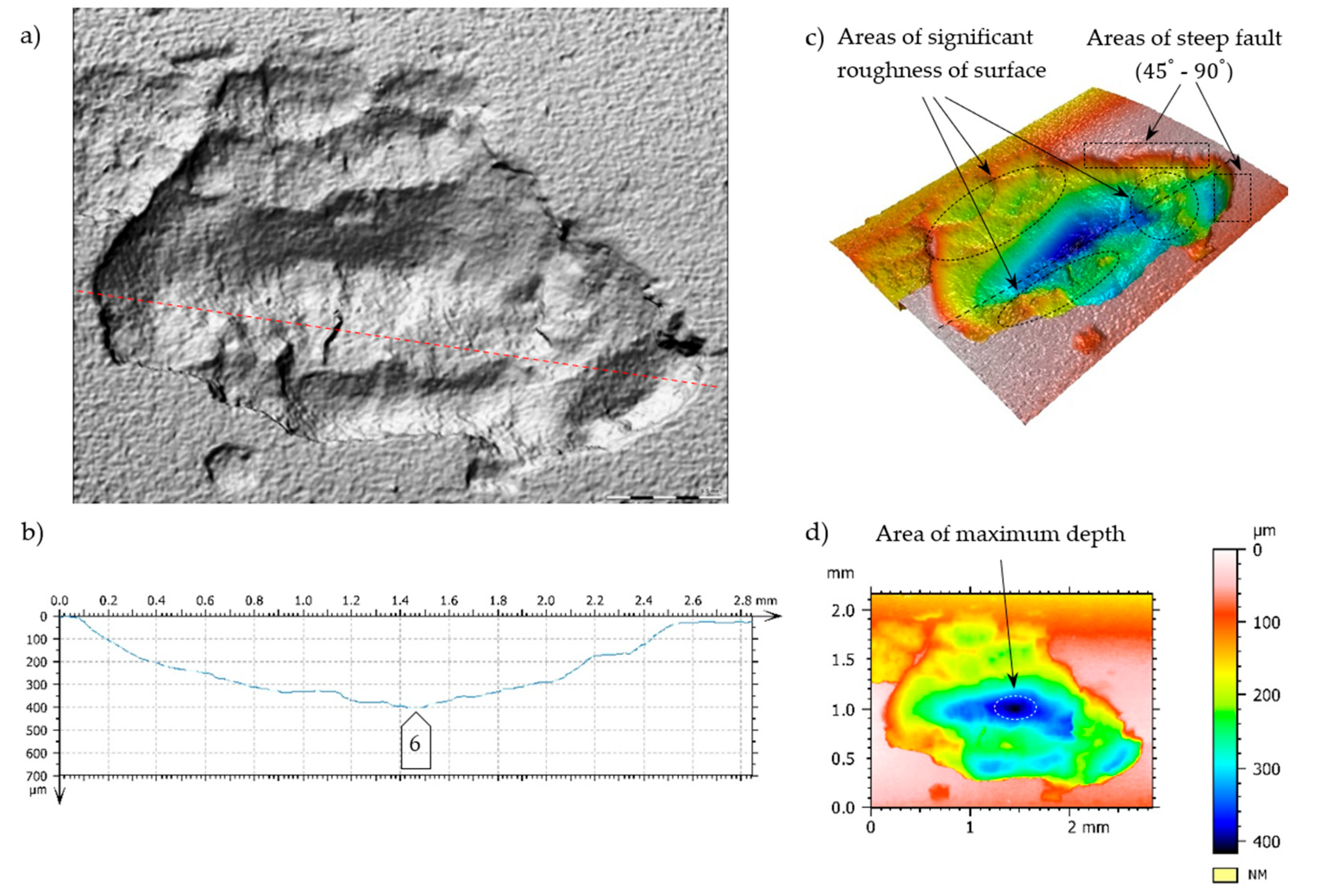
Figure 10.
Fatigue pit (pitting) on the tooth working surface - magnitude 10x. a) and b) superficial 3D view - pseudocolour of surface with visualization of depth, c) profile curve,----- - cross-section line, □ - indication of breaches edges, inclined at the angle close to 90° to the surfaces under analysis, on the cross-section.
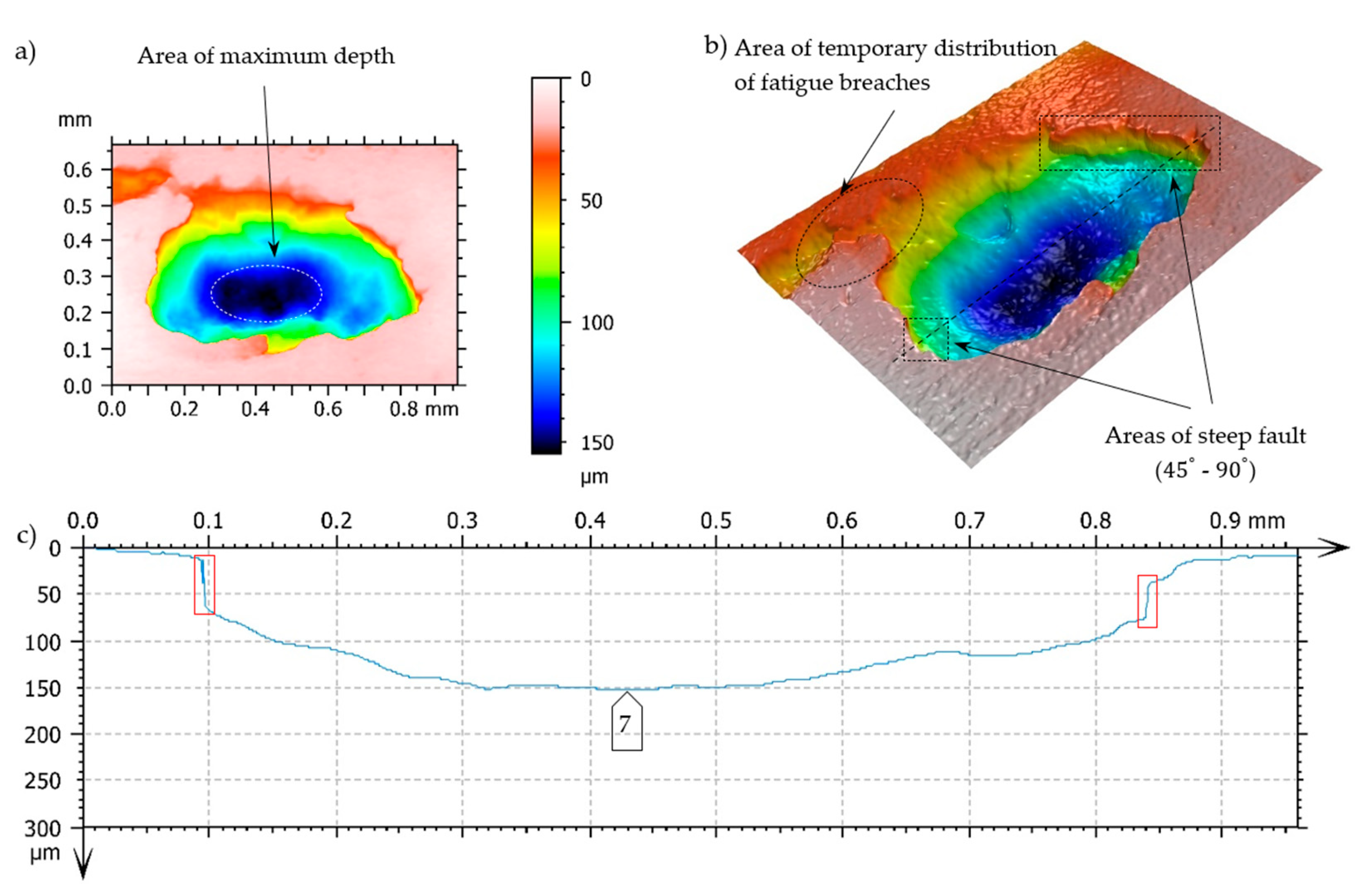
Figure 11.
Fatigue pit (pitting) on the tooth working surface - magnitude 10x. a) and b) superficial view 3D - pseudocolour of surface with visualization of depth, c) profile curve, ----- - line of cross-section, □ - indication of breaches edges, inclined at the angle close to 90° to the surfaces under analysis, on the cross - section.
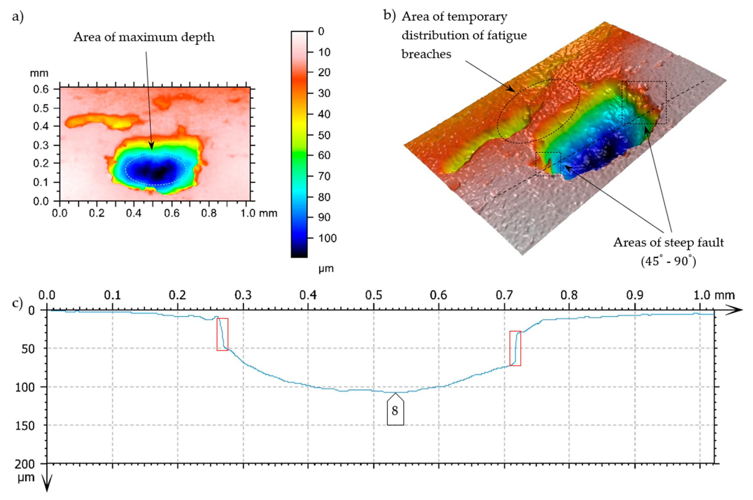
Figure 12.
Fatigue pit (pitting) on the tooth working surface - magnitude 10x. a) and b) superficial view 3D - pseudocolour of surface with visualization of depth, c) profile curve, ----- - line of cross - section, □ - indication of breaches edges, inclined at the angle close to 90° to the surfaces under analysis, on the cross-section.
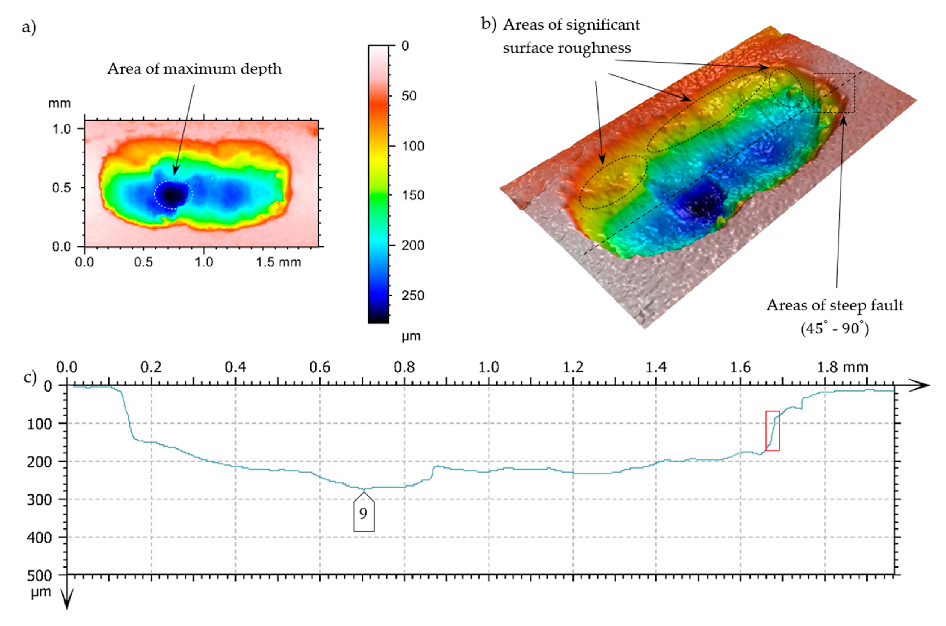
Figure 13.
Graphical presentation of the data from Table 2.
Figure 13.
Graphical presentation of the data from Table 2.
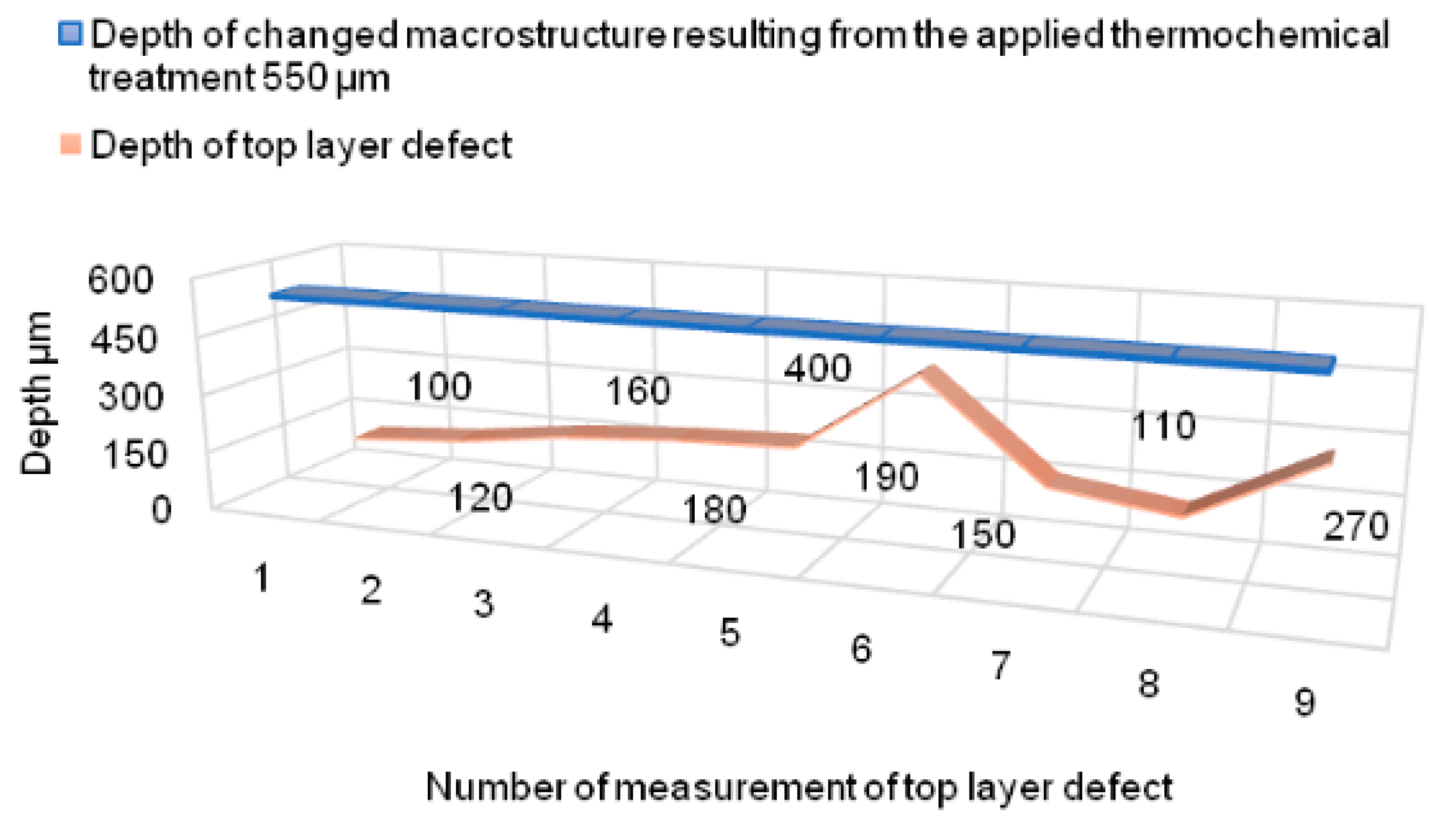

Table 1.
Average value (from three measurements) of the specimen chemical composition [42, and the requirements of the standard PN-89/H-84030-02].
Table 1.
Average value (from three measurements) of the specimen chemical composition [42, and the requirements of the standard PN-89/H-84030-02].
| % | C | Mn | Si | P | S | Cr | Ni | Mo | V |
| Tested material | 0.2140 | 0.6350 | 0.3510 | 0.0160 | 0.0030 | 1.3300 | 1.6400 | 0.2670 | 0.0060 |
| 17HNM acc. to PN 89/H-84030 |
0.14-0.19 | 0.40-0.70 | 0.17-0.37 | 0.035 | 0.035 | 1.50-1.80 | 1.40-1.70 | 0.25-0.35 | - |
| % | Cu | Al | Ti | Nb | Co | As | B | Pb | Zr |
| Tested material | 0.1790 | 0.0180 | 0.0030 | 0.0000 | 0.0140 | 0.0210 | 0.0020 | 0.0090 | 0.0030 |
| 17HNM acc. to PN 89/H-84030 |
- | - | - | - | - | - | - | - | - |
Table 2.
Geometric characteristics of chippings and an analysis of selected values in relation to the depth changes of macrostructure resulting from the applied superficial thermochemical treatment.
Table 2.
Geometric characteristics of chippings and an analysis of selected values in relation to the depth changes of macrostructure resulting from the applied superficial thermochemical treatment.
| I | II mm |
III µm |
|---|---|---|
| 1 | 0.8 | 100 |
| 2 | 0.7 | 120 |
| 3 | 0.8 | 160 |
| 4 | 1.3 | 180 |
| 5 | 1.95 | 190 |
| 6 | 2.5 | 400 |
| 7 | 0.75 | 150 |
| 8 | 0.5 | 110 |
| 9 | 0.85 | 270 |
I - no. of defect, II - maximum dimension of chipping measured in parallel to the tooth flank pitch line (+/-0.05mm), III - maximum depth of chipping measured in relation to the local flank pitch line surface in the defect vicinity (+/- 5 μm).
Disclaimer/Publisher’s Note: The statements, opinions and data contained in all publications are solely those of the individual author(s) and contributor(s) and not of MDPI and/or the editor(s). MDPI and/or the editor(s) disclaim responsibility for any injury to people or property resulting from any ideas, methods, instructions or products referred to in the content. |
© 2024 by the authors. Licensee MDPI, Basel, Switzerland. This article is an open access article distributed under the terms and conditions of the Creative Commons Attribution (CC BY) license (http://creativecommons.org/licenses/by/4.0/).
Copyright: This open access article is published under a Creative Commons CC BY 4.0 license, which permit the free download, distribution, and reuse, provided that the author and preprint are cited in any reuse.


