
Submitted:
15 March 2024
Posted:
18 March 2024
You are already at the latest version
Abstract
The incremental sheet forming represents a relatively recent technology that guarantees high customization, thanks to the layered manufacturing principle typical of rapid prototyping, and cost-effectiveness, because it does not require dedicated equipment. Research has initially shown that this process is effective in metal materials capable of withstanding plastic deformation but, in recent years, the interest in this technique has been increasing for the manufacture of complex polymer sheet components as an alternative to the conventional technologies, based on heating-shaping-cooling manufacturing routes. Conversely, incremental formed polymer sheets can suffer from some peculiar defects, for example twisting. To reduce the risk of this phenomenon and the occurrence of failures, a viable way is to choose toolpath strategies that make the tool/sheet contact conditions less severe, and this represents the main goal of the present research. Polycarbonate sheets were worked by incremental forming; in detail, cone frusta with a fixed wall angle were manufactured with a reference and a stair toolpath strategy, and both the forming forces and the twist angle were monitored. The analysis of the results highlighted that a stair toolpath involving an alternation of diagonal up and vertical down steps represents a useful strategy to mitigate the forming forces and, with them, the occurrence of the twisting phenomenon in incremental formed thermoplastic sheets.
Keywords:
incremental forming
; polycarbonate
; toolpath strategy
; forming forces
; twisting
1. Introduction
Polymeric materials show good properties like light-weight, strength, corrosion resistance, price, etc. that make them strongly used in the manufacturing industry [1]. Typical parts made of thermoplastics are manufactured with repetitive operations of heating, shaping, and cooling [2]; usually, these operations are oriented to mass production both for the energy costs and the investments in equipment and tools. Moreover, it is frequent that the procedures usually used in the sheet metal forming are employed for the manufacture of polymer sheet parts of different shapes [3]; in these cases, the forming processes strongly depend on the material properties and the forming temperature, so as highlighted in [4].
During the last decade, the interest in developing procedures with a higher level of flexibility has increased progressively, due to the significant advances in the use of computers applied to manufacturing. For example, think the additive manufacturing technologies [5] or the incremental sheet forming (ISF) that can guarantee customized production without dedicated dies, in a brief time and at a low cost, starting from sheets of pure metals, alloys, polymers, and composites [6,7].
ISF represents a viable alternative to conventional technologies based on heating-shaping-cooling manufacturing routes, guaranteeing high levels of materials’ formability and the carrying out at room temperature; a clamped sheet is progressively deformed by a forming tool that, controlled by a CNC machine, describes a path to manufacture the final part geometry [8]. Due to its characteristics of flexibility, it is strongly oriented toward the production of batches with small and medium size; furthermore, recent studies have highlighted that ISF for polymeric parts allows reducing energy consumption, compared to conventional processes [9].
The first studies on the incremental forming of polymeric sheets were conducted by Franzen et al. [10] and focused on the feasibility of ISF for polyvinylchloride (PVC) sheets, while its extendibility to other commercial polymers was demonstrated by Martins et al. [11].
Significant analyses on the influence of the main process parameters were conducted on polypropylene (PP) sheets in [12] as well as on polyamide (PA), polycarbonate (PC), polyethylene terephthalate (PET) and PVC [13,14,15] to determine their formability limits. Other studies were aimed at finding new methods to better investigate the formability limits [2,16].
Moreover, the behaviour of new materials like the biocompatible polycaprolactone (PCL) when incrementally formed was analysed [4], as well as the efficiency of new solutions to improve the quality of the ISF polymer parts; consider, for example, some previous authors’ works that investigated a prior cold-rolling process of the sheets [17] or their self-heating as the effect of the feed rate and the spindle [18].
Another relevant field of investigation, strictly linked to formability, was related to the failure and defect modes. So as reported by [10], the polymer sheets processed by ISF can be affected by ductile fracture at the transition region between the wall and the corner radius or tearing along the walls, and defects like wrinkling and twisting. The occurrence of these defects, although not representing sheet fractures, limits the formability of the ISF parts. Moreover, they are strictly connected; in particular, the wrinkles can be twisted around the axis of revolution in the direction of tool rotation. Then, the twisting can worsen the quality of polymer parts made by ISF; it is a phenomenon due to an uncontrolled pivoting of the formed parts around the clamping frame and is caused by the tangential forces (with the consequent in-plane shear) that the forming tool exerts on the sheet.
The twisting phenomenon interests all the materials, like metals [19], but is particularly perceived by thermoplastic sheets [20], due to their softer nature. A viable way to prevent it is to act on the toolpath strategy; for example, it can be significantly reduced by using an alternating toolpath in anticlockwise and clockwise directions, so as shown by [8] and, for PC parts, by [21]. Another way provides for reducing the forming forces that act in the sheet plane; note that the occurrence of the phenomenon is more probable for higher and more regular plane forces, because they determine a combination of continued strain accumulation and asymmetric strain levels [22,23].
According to what reported above and following previous authors’ work aiming to optimize the forming process through a numerical approach [24,25], this paper investigates how to reduce the twisting phenomenon and, with it, the occurrence of failures, through the choice of toolpath strategies that make the tool/sheet contact conditions less severe. Cone frusta with fixed wall angle were produced by thin PC sheets, using the single-point incremental forming (SPIF) by setting typical process parameters [21] and different toolpath strategies; SPIF represents the simplest variant of ISF and involves the use of a simple tool, a clamping frame, and the absence of dies.
The material used in this study is an amorphous thermoplastic polymer also known as a “transparency metal” due to its relevant mechanical and physiochemical properties; significant toughness, stiffness, strength, heat and flame resistance, and dimensionally stability, among others [26], make it strongly used in several applications in the fields of communication, transport, medical apparatus, aerospace environment, and so on [27].
Some features from the experimental campaign were analysed, i.e., the forming forces and the twisting angle, to show the potential of the optimized toolpath strategy of reducing both and, also, the risk of failures and other defects on incrementally formed polymer parts.
2. Materials and Methods
The experimental campaign on PC sheets with a thickness t = 1.5 mm was conducted carrying out SPIF tests at room temperature, by a C.B. Ferrari high speed four-axis vertical machining centre that drives the forming tool, a hemispherical head stainless steel stylus with a diameter D = 10 mm; the main materials’ properties of the sheets and of the forming tool are reported in [24].
The tests provided the manufacture of cone frusta with a fixed wall angle; these components were characterized by the height h = 20 mm, the radius of the major base R = 35 mm, the wall angle α = 60° and a square flange with a side L = 100 mm. The blocking system of the sheet was constituted by a clamping frame. The geometrical features of the components and of the forming tool with their values are reported in Figure 1, while the experimental setup during a SPIF test is shown in Figure 2.
The forming process under exam involved a localized and incremental deformation of the sheet as the effect of its interaction with the forming tool; the risks of failing tests due to the tool/sheet interaction were reduced by lubricating the sheets with mineral oil for cold forming [28].
Two different toolpath strategies (of which a not-to-scale schematization is reported in Figure 3) were considered, and, for both, a feed rate of 1000 mm/min was set. The two strategies required that the tool covered 60 equally spaced points for each complete turn of a conical helix, while the vertical distance between two consecutive turns was equal to vs = 1 mm (see, in Figure 3a,b respectively, the three-dimensional representation of some turns of the helix and a complete turn in the XY-plane view, common for the two toolpath strategies).
With the first strategy, the distance between two consecutive points was covered by a segment; it can be considered as a reference toolpath (ref_tp) strategy. The second strategy (hr_tp) provided for an alternation of an upward and a vertical down segment between two consecutive points of the helix; this stair path was tested for three different values of the height of the ramp (hr) of the upward segment. The three tested values were equal to hr = 0.5 mm (hr0.5_tp), hr = 1.0 mm (hr1.0_tp) and hr = 1.5 mm (hr1.5_tp); for the last one, also a test without lubrication (hr1.5_tp_dry) was carried out, to evaluate its influence for the toolpath which is expected to be the less severe [25]. The differences between these strategies can be appreciated in the representation of a half turn in the YZ-plane view of Figure 3c. Note that the arrows in Figure 3 indicates the toolpath direction.
To control the process, two components of the forming forces were monitored and acquired; in detail the vertical (FZ) and one horizontal component (FX) were acquired through a Kistler 9257A piezoelectric dynamometer at 2000 Hz and subsequently filtered by means of a NI 9239 input module and the VBA 1.0 B software (see the reference axes for the forces and the position of the dynamometer in Figure 2).
Moreover, also the twist angle θ was evaluated as a measure of the twisting magnitude; to do this, the bottom of the undeformed sheets (which did not come in contact with the forming tool) was marked with a cross and its rotation at the end of the test, compared to its original position, was measured [29]. Figure 4 reports a CAD representation of this evaluation.
3. Results
All the tests were carried out without the occurrence of failures and wrinkles; at the same time, they all showed twisting. Concerning this, you can see in Figure 5 the bottom surface of a sound component created by the ref_tp (Figure 5a) and one by the hr1.5_tp (Figure 5b); these toolpaths represent the limit cases in terms of severity of the contact conditions.
The complete trend of the two components of the forming forces for the above-mentioned toolpaths weas reported in Figure 6. See that for a simpler comparison of the trends, the processing time on the abscissa axis is reported in percentage terms, because it is not the same for the different toolpaths, due to their different lengths. In this regard, Table 1 reports the forming time depending on the toolpath.
Finally, Table 2 reports the twist angle for the different toolpaths (for the hr1.5_tp, both in lubricated and dry conditions).
4. Discussion
Following the first sentence of the results, all the tests were carried out without incurring failures; then, all the toolpaths guarantee the correct execution of the SPIF process. This is in line with what expected, in light of the results in terms of formability from varying wall angle cone frusta tests, carried out by the authors and presented in a previous work [21], which highlighted a maximum wall angle in similar conditions of about 80° (significantly higher than the one chosen for the fixed wall angle of the cone frusta manufactured in this experimental campaign).
Passing to the analysis of the forming forces, a qualitative evaluation of their trend passes for the interpretation of the images in Figure 6; a better interpretation is possible by observing a particular of them for the two limit cases in a 70 ÷ 80 percentage time range (see Figure 7).
From Figures 6a and 7a it is possible to note that the reference strategy shows a trend that is typical for the SPIF of cone frusta when using a conical helix toolpath [30], as a result of the continuous vertical down movement of the forming tool that involves a continuous and constant tool/sheet contact condition. The vertical component follows the tensile trend of the material, with a first significant and a second more gradual increase with the forming time. Little oscillations are due to a little variability of the sheet stiffness because the distance of the tool (describing circular turns) from the frame (with a square shape) is not constant. The horizontal component shows a typical sinusoidal trend, with increasing amplitude as well as the vertical one.
The stair path strategy (see Figures 6b and 7b for the hr1.5_tp) also presents typical SPIF trends, but with a fluctuation that follows the diagonal up and vertical down parts of the toolpath and is a consequence of a partial elastic recovery [31].
To compare quantitatively the forming forces for the different toolpaths, some relevant information was collected from the data of the two last complete turns (see the part of the trend in the rectangular box in Figure 6a). From this data set, a boxplot of the vertical component of the forming forces is generated, reporting five relevant values (see Figure 8a): minimum, first quartile, second quartile (median), third quartile and maximum. Moreover, Figure 8b reports the average of FZ and of the absolute values of FX, labelled as FZ,m and |FX|m respectively.
As anticipated, the fluctuation of the forces increases from the reference to the stair path strategy and, for the last one, with the ramp height (see Figure 8a); conversely, the mean value of both the force components decreases (see Figure 8b). Despite this, not even for the limit case (hr1.5_tp) the forces go to zero; then, the selected toolpaths do not determine no-contact conditions between the tool and the sheet in any time of the process. Furthermore, it is possible to observe that for the toolpath guaranteeing the less severe contact conditions, the lubrication results to be irrelevant. This aspect, added up the FEM prediction of reduced energy consumption [25], makes the hr1.5_tp a viable way on the improvement of ISF towards more efficiency and green manufacturing process [32].
Finally, the considerations on the forming forces, particularly the ones summarized in Figure 8b, translate into similar conclusions for the twisting phenomenon, with its reduction for the stair path strategy and with the increase of ramp height (lubrication conditions irrelevant for the limit case), as highlighted by the data in Table 2.
5. Conclusions
In the present paper, the results of an experimental campaign based on the manufacture by the single-point incremental forming of fixed wall angle cone frusta from polycarbonate sheets, 1.5 mm in thickness, were presented. The aim was to investigate the influence of the toolpath strategy on the forming forces and the magnitude of the twisting phenomenon.
The tests highlighted that, compared to a reference toolpath, the choice of a stair path strategy that alternates diagonal up and vertical down steps allows to reduce the forming forces, due to a partial elastic recovery during the process; furthermore, a comparison between the tests carried out in lubricated and dry conditions when using this strategy with a ramp height equal to 1.5 mm shows the irrelevancy of the lubrication conditions and this implies a positive impact on the environment. Finally, a slight reduction of the twist angle occurs when using the optimized strategy.
Future works could aim to extend the experimental research and to use numerical methods for a more effective optimization of the incremental sheet forming; different toolpath strategies can be investigated to further reduce the forming forces and the defectiveness of the components formed incrementally, as well as their influence on relevant features concerning the dimensional accuracy and the surface quality.
Author Contributions
Conceptualization, A.F. and M.D.; data curation, A.F., L.B and D.D.F; writing—original draft preparation, A.F.; writing—review and editing, A.F. and M.D.; supervision, A.F.; funding acquisition, A.F., and L.B. All authors have read and agreed to the published version of the manuscript.
Funding
This work was supported by the “Programma per il Finanziamento della Ricerca di Ateneo (FRA) 2022” of the University of Naples Federico II.
Data Availability Statement
Not applicable.
Conflicts of Interest
The authors declare no conflicts of interest.
References
- Rosa-Sainz, A.; Centeno, G.; Silva, M.B.; Vallellano, C. Experimental Failure Analysis in Polycarbonate Sheet Deformed by Spif. J. Manuf. Process. 2021, 64, 1153–1168. [Google Scholar] [CrossRef]
- Rosa-Sainz, A.; Centeno, G.; Silva, M.B.; Andrés López-Fernández, J.; Jesus Martínez-Donaire, A.; Vallellano, C. On the Determination of Forming Limits in Polycarbonate Sheets. Materials (Basel). 2020, 13, 928. [Google Scholar] [CrossRef]
- Shaw, M.T. Cold Forming of Polymeric Materials. Annu. Rev. Mater. Sci. 1980, 10, 19–42. [Google Scholar] [CrossRef]
- Bagudanch, I.; Centeno, G.; Vallellano, C.; Garcia-Romeu, M.L. Revisiting Formability and Failure of Polymeric Sheets Deformed by Single Point Incremental Forming. Polym. Degrad. Stab. 2017, 144, 366–377. [Google Scholar] [CrossRef]
- Tofail, S.A.M.; Koumoulos, E.P.; Bandyopadhyay, A.; Bose, S.; O’Donoghue, L.; Charitidis, C. Additive Manufacturing: Scientific and Technological Challenges, Market Uptake and Opportunities. Mater. Today 2018, 21, 22–37. [Google Scholar] [CrossRef]
- Bertini, L.; Kubit, A.; Al-Sabur, R.; Gradzik, A.; Ochał, K.; Slota, J.; Korzeniowski, M. Investigating Residual Stresses in Metal-Plastic Composites Stiffening Ribs Formed Using the Single Point Incremental Forming Method. Materials (Basel). 2022, 15, 8252. [Google Scholar] [CrossRef]
- Behera, A.K.; de Sousa, R.A.; Ingarao, G.; Oleksik, V. Single Point Incremental Forming: An Assessment of the Progress and Technology Trends from 2005 to 2015. J. Manuf. Process. 2017, 27, 37–62. [Google Scholar] [CrossRef]
- Jeswiet, J.; Micari, F.; Hirt, G.; Bramley, A.; Duflou, J.; Allwood, J. Asymmetric Single Point Incremental Forming of Sheet Metal. CIRP Ann. 2005, 54, 88–114. [Google Scholar] [CrossRef]
- Bagudanch, I.; Garcia-Romeu, M.L.; Sabater, M. Incremental Forming of Polymers: Process Parameters Selection from the Perspective of Electric Energy Consumption and Cost. J. Clean. Prod. 2016, 112, 1013–1024. [Google Scholar] [CrossRef]
- Franzen, V.; Kwiatkowski, L.; Martins, P.A.F.; Tekkaya, A.E. Single Point Incremental Forming of PVC. J. Mater. Process. Technol. 2009, 209, 462–469. [Google Scholar] [CrossRef]
- Martins, P.A.F.; Kwiatkowski, L.; Franzen, V.; Tekkaya, A.E.; Kleiner, M. Single Point Incremental Forming of Polymers. CIRP Ann. 2009, 58, 229–232. [Google Scholar] [CrossRef]
- Le, V.S.; Ghiotti, A.; Lucchetta, G. Preliminary Studies on Single Point Incremental Forming for Thermoplastic Materials. Int. J. Mater. Form. 2008, 1, 1179–1182. [Google Scholar] [CrossRef]
- Marques, T.A.; Silva, M.B.; Martins, P.A.F. On the Potential of Single Point Incremental Forming of Sheet Polymer Parts. Int. J. Adv. Manuf. Technol. 2012, 60, 75–86. [Google Scholar] [CrossRef]
- Bagudanch, I.; Garcia-Romeu, M.L.; Centeno, G.; Elías-Zúñiga, A.; Ciurana, J. Forming Force and Temperature Effects on Single Point Incremental Forming of Polyvinylchloride. J. Mater. Process. Technol. 2015, 219, 221–229. [Google Scholar] [CrossRef]
- Davarpanah, M.A.; Mirkouei, A.; Yu, X.; Malhotra, R.; Pilla, S. Effects of Incremental Depth and Tool Rotation on Failure Modes and Microstructural Properties in Single Point Incremental Forming of Polymers. J. Mater. Process. Technol. 2015, 222, 287–300. [Google Scholar] [CrossRef]
- Martínez-Donaire, A.J.; García-Lomas, F.J.; Vallellano, C. New Approaches to Detect the Onset of Localised Necking in Sheets under Through-Thickness Strain Gradients. Mater. Des. 2014, 57, 135–145. [Google Scholar] [CrossRef]
- Durante, M.; Formisano, A.; Boccarusso, L.; Langella, A. Influence of Cold-Rolling on Incremental Sheet Forming of Polycarbonate. Mater. Manuf. Process. 2020, 35, 328–336. [Google Scholar] [CrossRef]
- Formisano, A.; Lambiase, F.; Durante, M. Polymer Self-Heating during Incremental Forming. J. Manuf. Process. 2020, 58, 1189–1199. [Google Scholar] [CrossRef]
- Formisano, A.; Boccarusso, L.; Capece Minutolo, F.; Carrino, L.; Durante, M.; Langella, A. Negative and Positive Incremental Forming: Comparison by Geometrical, Experimental, and FEM Considerations. Mater. Manuf. Process. 2017, 32, 530–536. [Google Scholar] [CrossRef]
- Zhu, H.; Ou, H.; Popov, A. Incremental Sheet Forming of Thermoplastics: A Review. Int. J. Adv. Manuf. Technol. 2020, 111, 565–587. [Google Scholar] [CrossRef]
- Durante, M.; Formisano, A.; Lambiase, F. Incremental Forming of Polycarbonate Sheets. J. Mater. Process. Technol. 2018, 253, 57–63. [Google Scholar] [CrossRef]
- Chang, Z.; Chen, J. Mechanism of the Twisting in Incremental Sheet Forming Process. J. Mater. Process. Technol. 2020, 276, 116396. [Google Scholar] [CrossRef]
- Duflou, J.R.; Vanhove, H.; Verbert, J.; Gu, J.; Vasilakos, I.; Eyckens, P. Twist Revisited: Twist Phenomena in Single Point Incremental Forming. CIRP Ann. 2010, 59, 307–310. [Google Scholar] [CrossRef]
- Formisano, A.; Durante, M.; Boccarusso, L.; Memola Capece, F. A Numerical Approach to Optimize the Toolpath Strategy for Polymers Forming. Mater. Res. Proc. 2023, 28, 1697–1702. [Google Scholar] [CrossRef]
- Formisano, A.; Boccarusso, L.; Durante, M. Optimization of Single-Point Incremental Forming of Polymer Sheets through FEM. Mater. 2023, Vol. 16, Page 451 2023, 16, 451. [Google Scholar] [CrossRef]
- Hou, Z.X.; Wu, J.; Wang, Z.R. A Study of the Bulge-Forming of Polycarbonate (PC) Sheet. J. Mater. Process. Technol. 2004, 151, 312–315. [Google Scholar] [CrossRef]
- Beşliu, I.; Tamaşag, I.; Slătineanu, L. An Experimental Study on Incremental Forming Process of Polycarbonate Sheets. Macromol. Symp. 2021, 395, 2000282. [Google Scholar] [CrossRef]
- Beșliu-Băncescu, I.; Slătineanu, L.; Dodun, O.; Nagîț, G. Influence of Lubrication and Cooling on the Quality of Single-Point Incremental Forming Parts of Polycarbonate Sheets. J. Manuf. Mater. Process. 2021, Vol. 5, Page 75 2021, 5, 75. [Google Scholar] [CrossRef]
- Durante, M.; Formisano, A.; Lambiase, F. Formability of Polycarbonate Sheets in Single-Point Incremental Forming. Int. J. Adv. Manuf. Technol. 2019, 102, 2049–2062. [Google Scholar] [CrossRef]
- Rosca, N.; Trzepieciński, T.; Oleksik, V. Minimizing the Forces in the Single Point Incremental Forming Process of Polymeric Materials Using Taguchi Design of Experiments and Analysis of Variance. Materials 2022, 15, 6453. [Google Scholar] [CrossRef]
- Wei, H.; Zhou, L.; Heidarshenas, B.; Ashraf, I.K.; Han, C. Investigation on the Influence of Springback on Precision of Symmetric-Cone-like Parts in Sheet Metal Incremental Forming Process. Int. J. Light. Mater. Manuf. 2019, 2, 140–145. [Google Scholar] [CrossRef]
- Liu, F.; Li, Y.; Ghafoor, S.; Cheng, Z.; Li, F.; Li, J. Sustainability Assessment of Incremental Sheet Forming: A Review. Int. J. Adv. Manuf. Technol. 2022, 119, 1385–1405. [Google Scholar] [CrossRef]
Figure 1.
Geometrical features of the fixed wall angle cone frusta and of the forming tool.
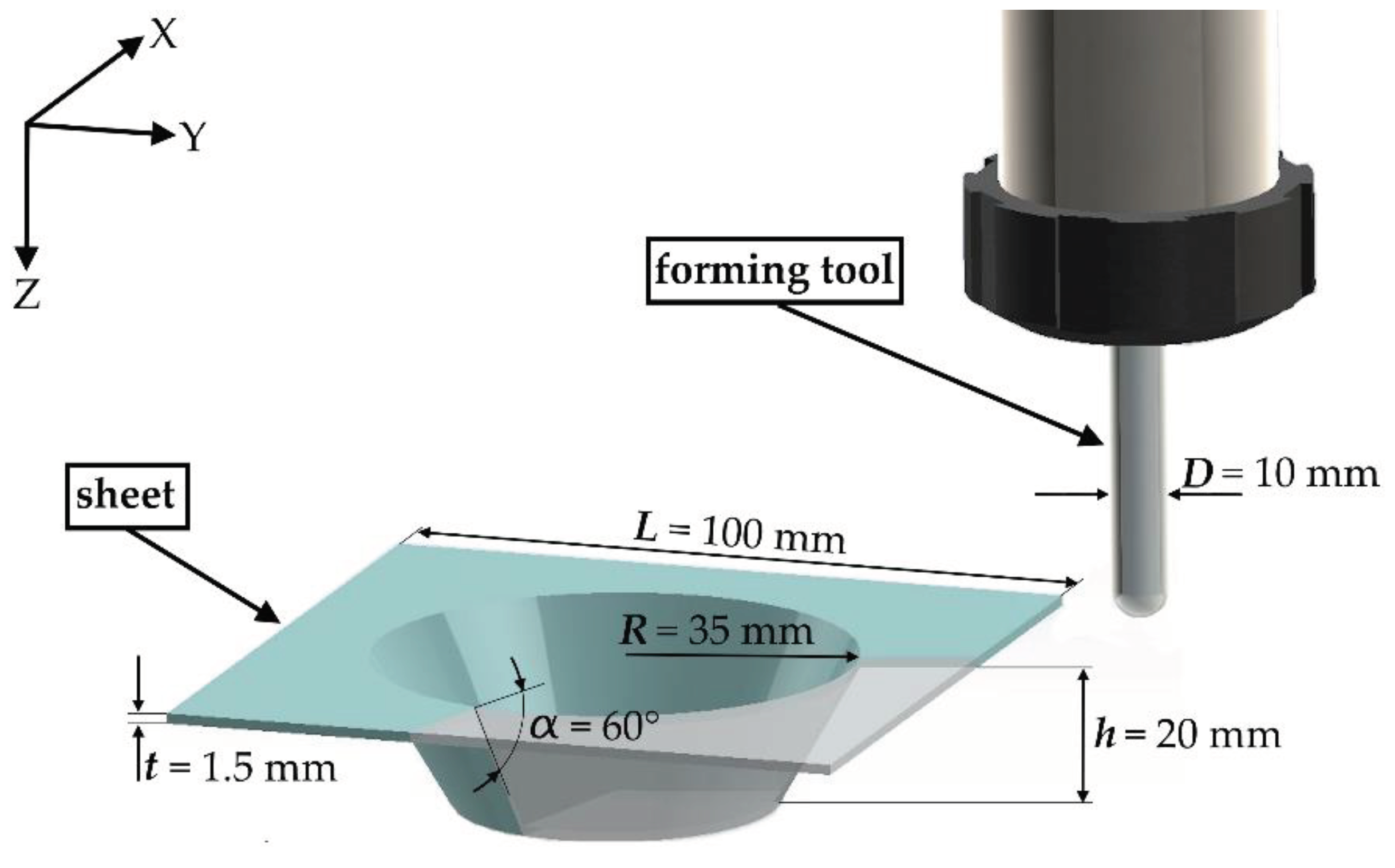
Figure 2.
Experimental setup during an incremental forming test.
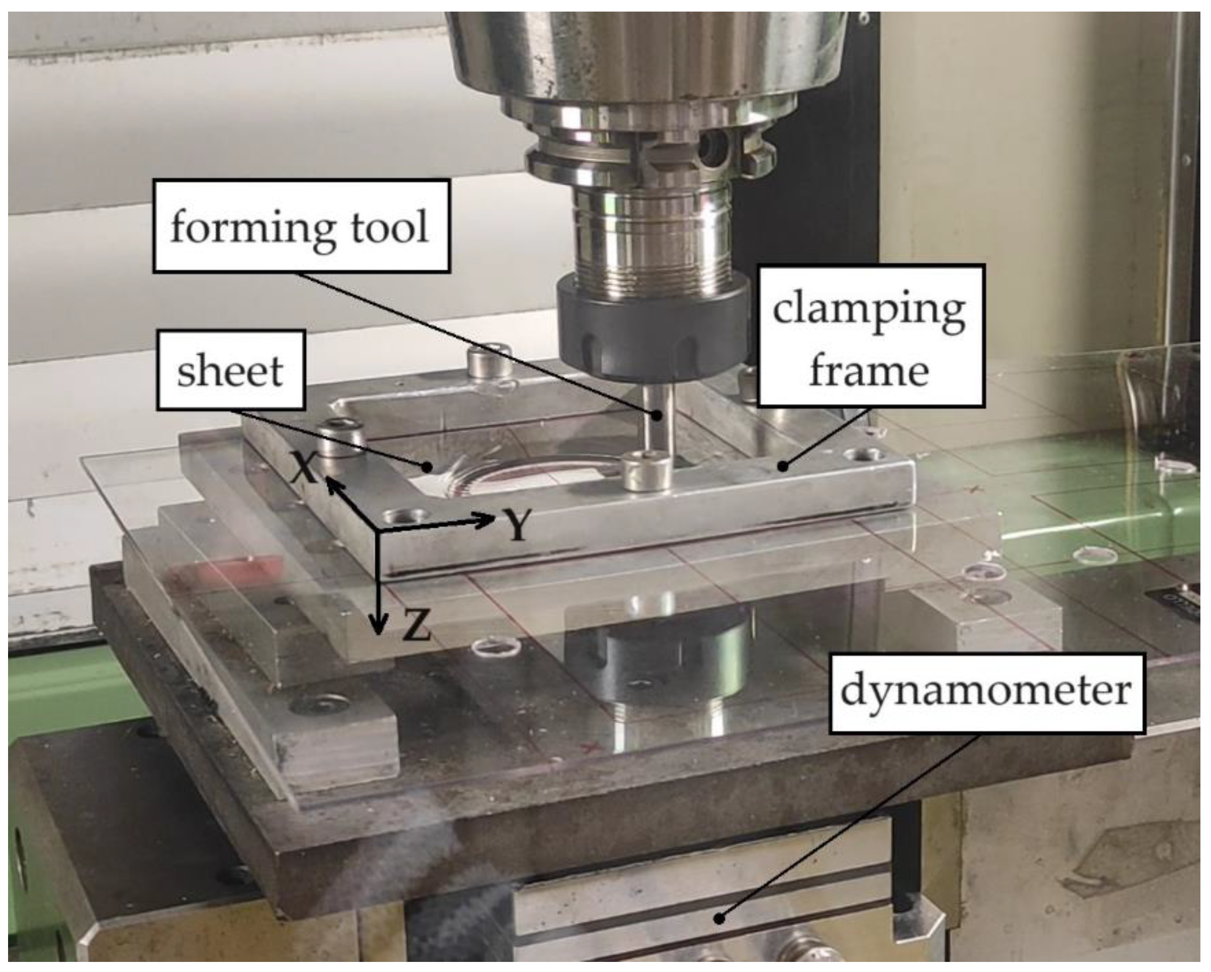
Figure 3.
Not-to-scale schematization of the toolpath strategies: (a) conical helix; (b) XY-plane and (c) YZ-plane views of the toolpaths.
Figure 3.
Not-to-scale schematization of the toolpath strategies: (a) conical helix; (b) XY-plane and (c) YZ-plane views of the toolpaths.
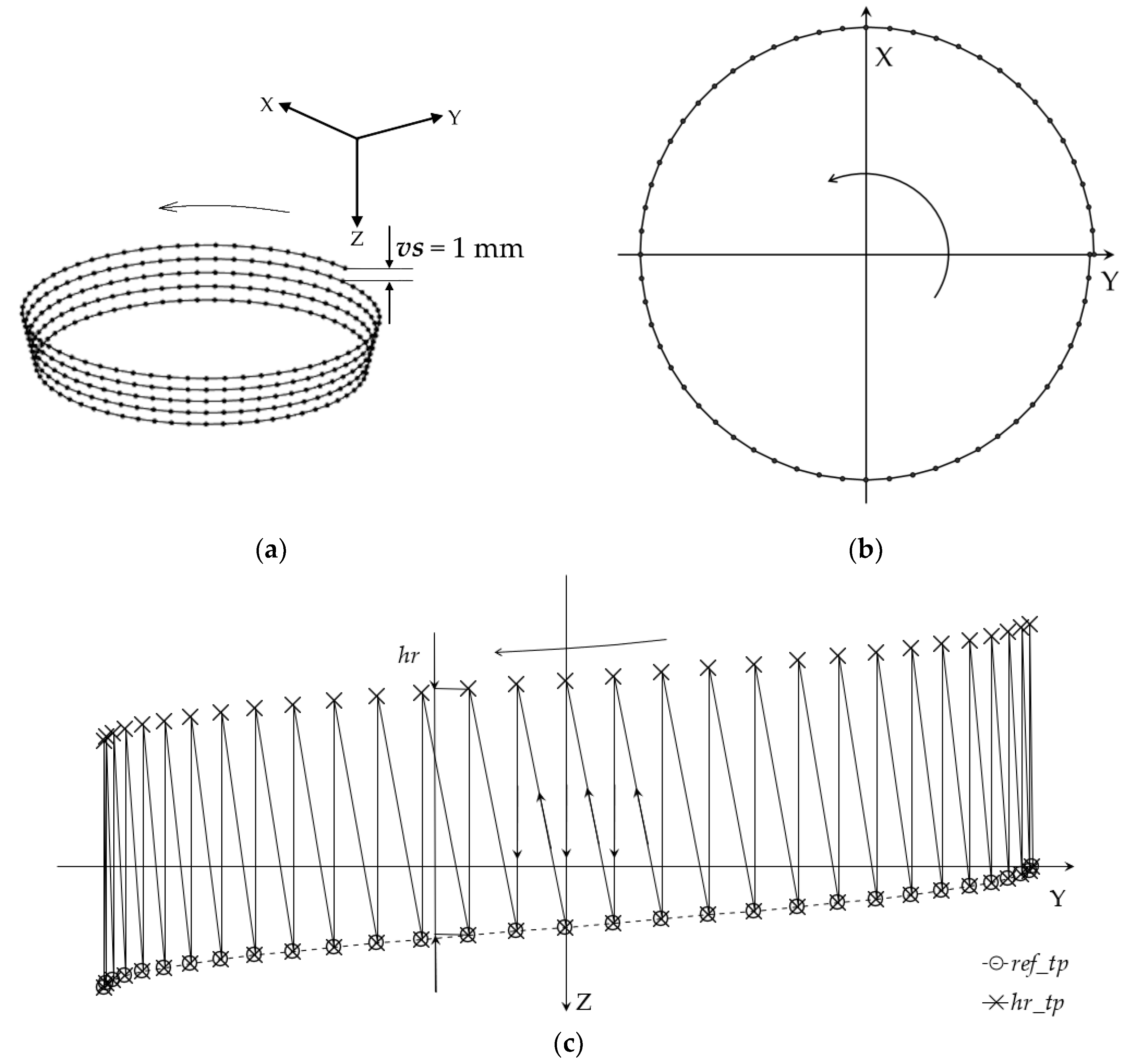
Figure 4.
CAD representation of the evaluation of the twist angle.
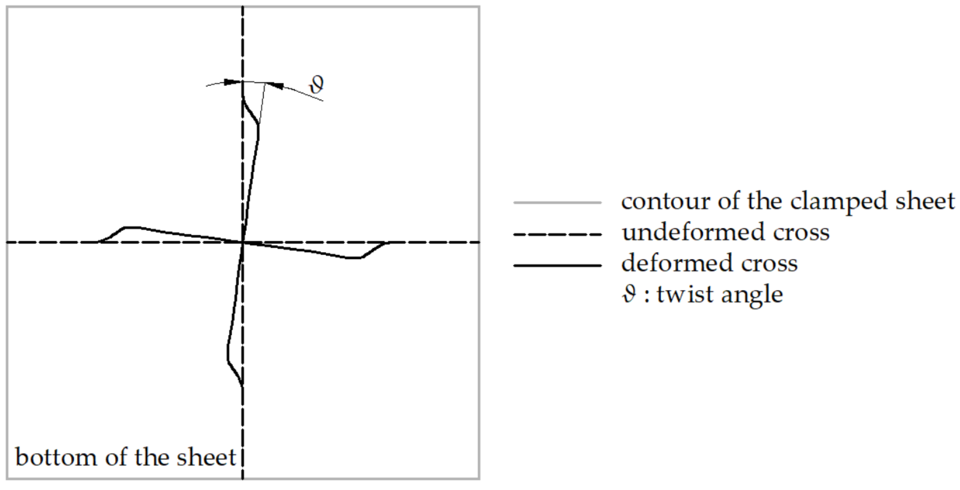
Figure 5.
Cone frustum manufactured by: (a) the ref_tp; (b) the hr1.5_tp.
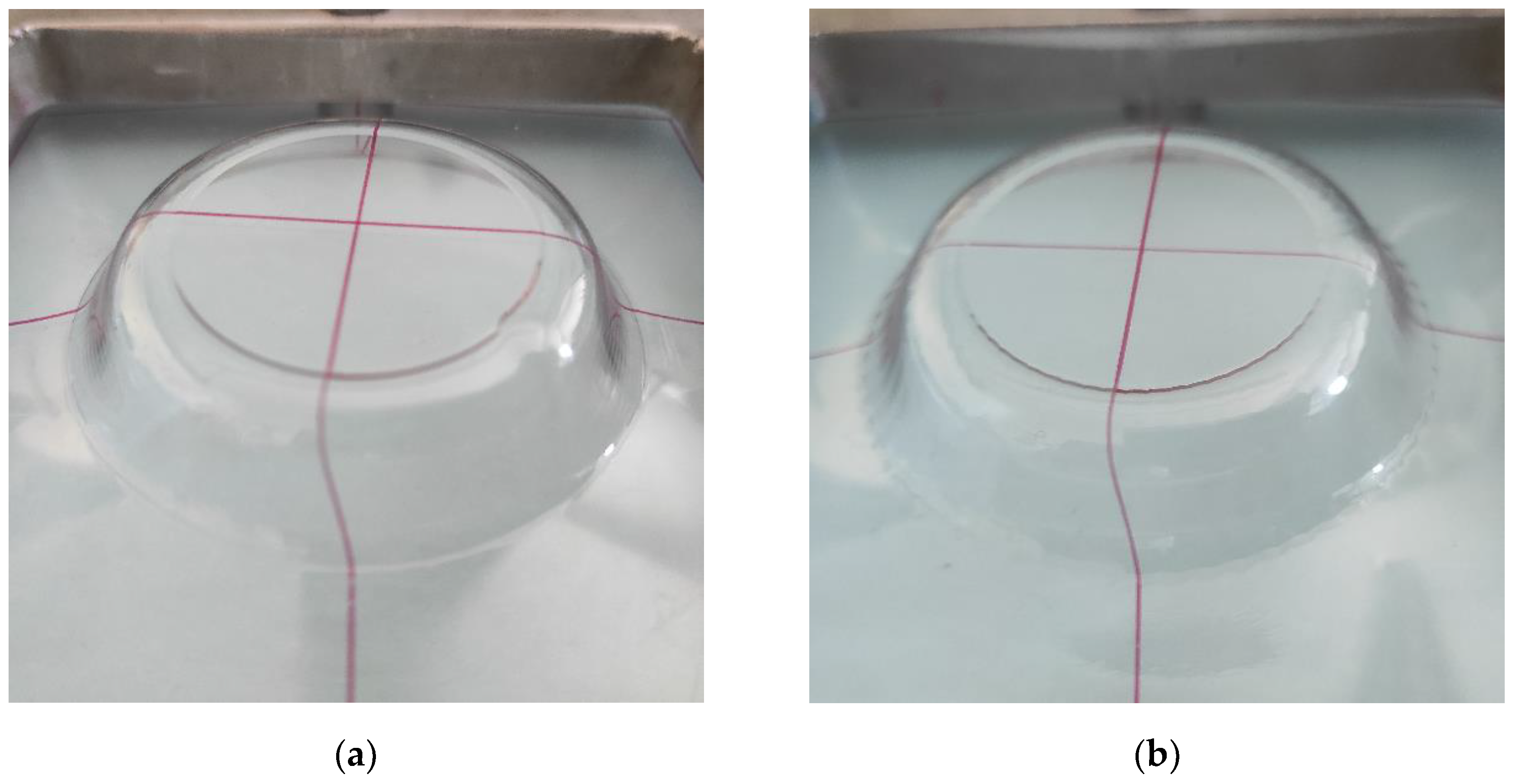
Figure 6.
Complete trend of the forming forces using: (a) the ref_tp; (b) the hr1.5_tp.
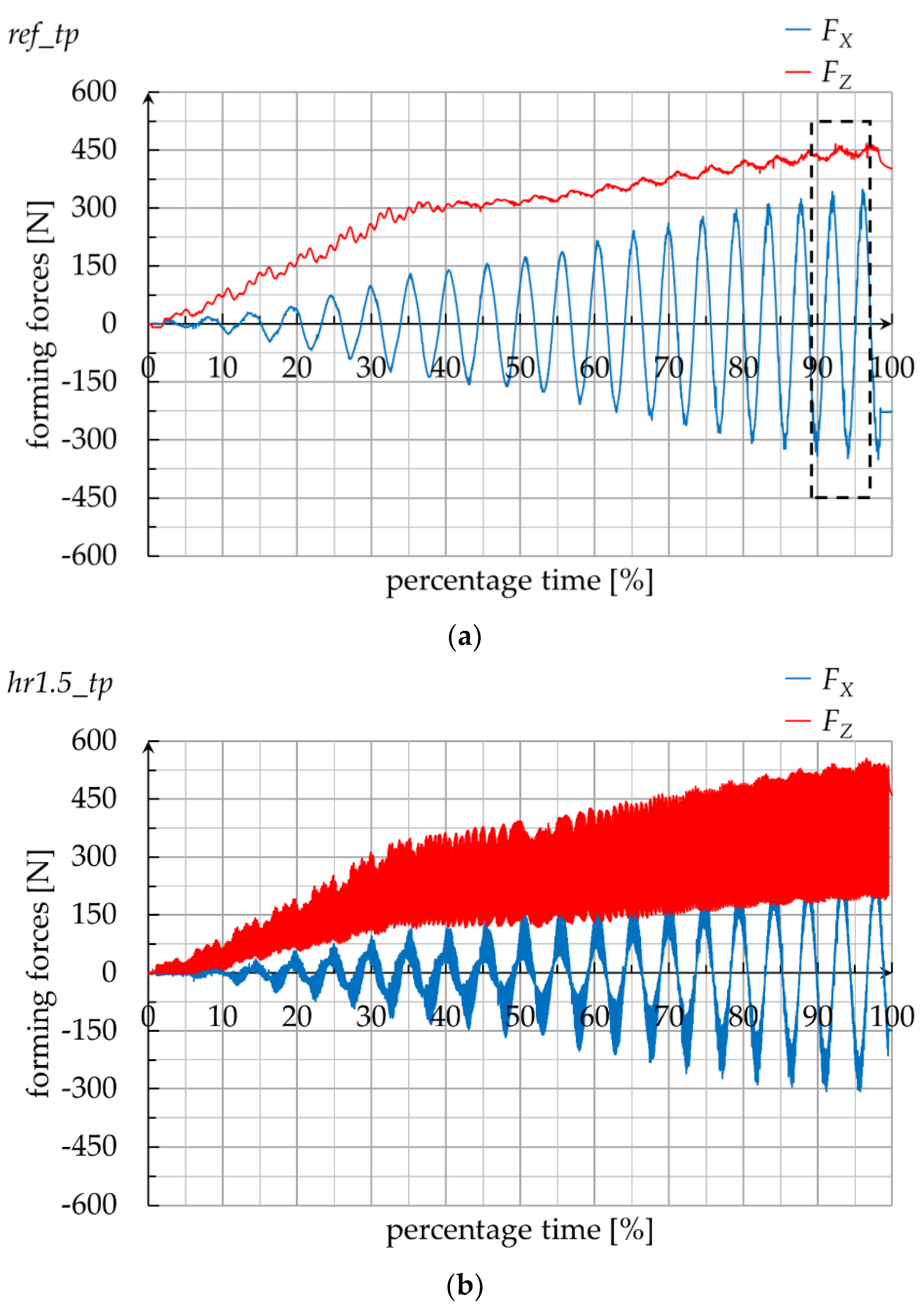
Figure 7.
70 ÷ 80 percentage time range trend of the forming forces using: (a) the ref_tp; (b) the hr1.5_tp.
Figure 7.
70 ÷ 80 percentage time range trend of the forming forces using: (a) the ref_tp; (b) the hr1.5_tp.
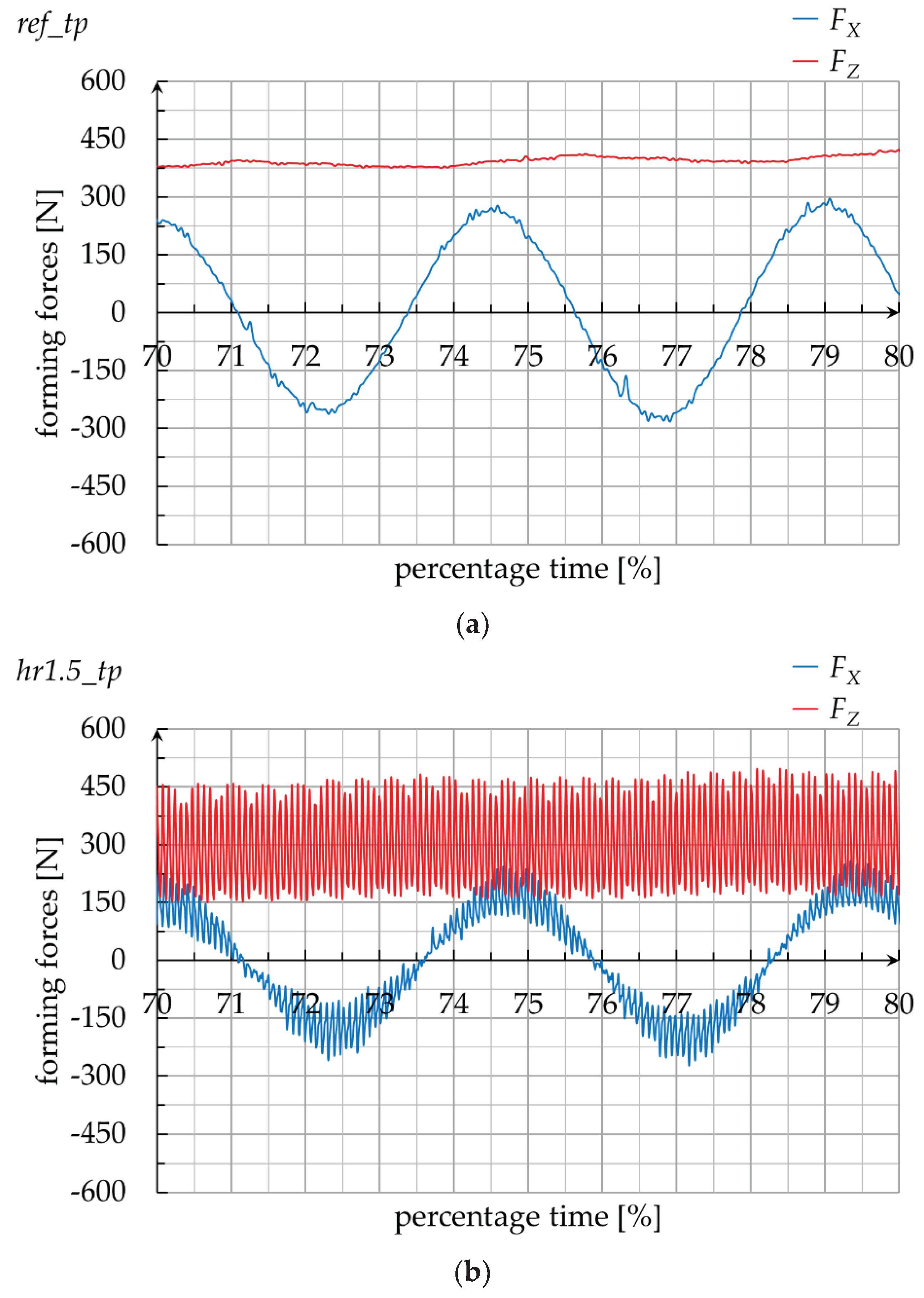
Figure 8.
Forming force data analyses from the last two complete turns of the different toolpaths: (a) boxplot for the vertical component; (b) average of the vertical component and of the absolute values of the horizontal component.
Figure 8.
Forming force data analyses from the last two complete turns of the different toolpaths: (a) boxplot for the vertical component; (b) average of the vertical component and of the absolute values of the horizontal component.
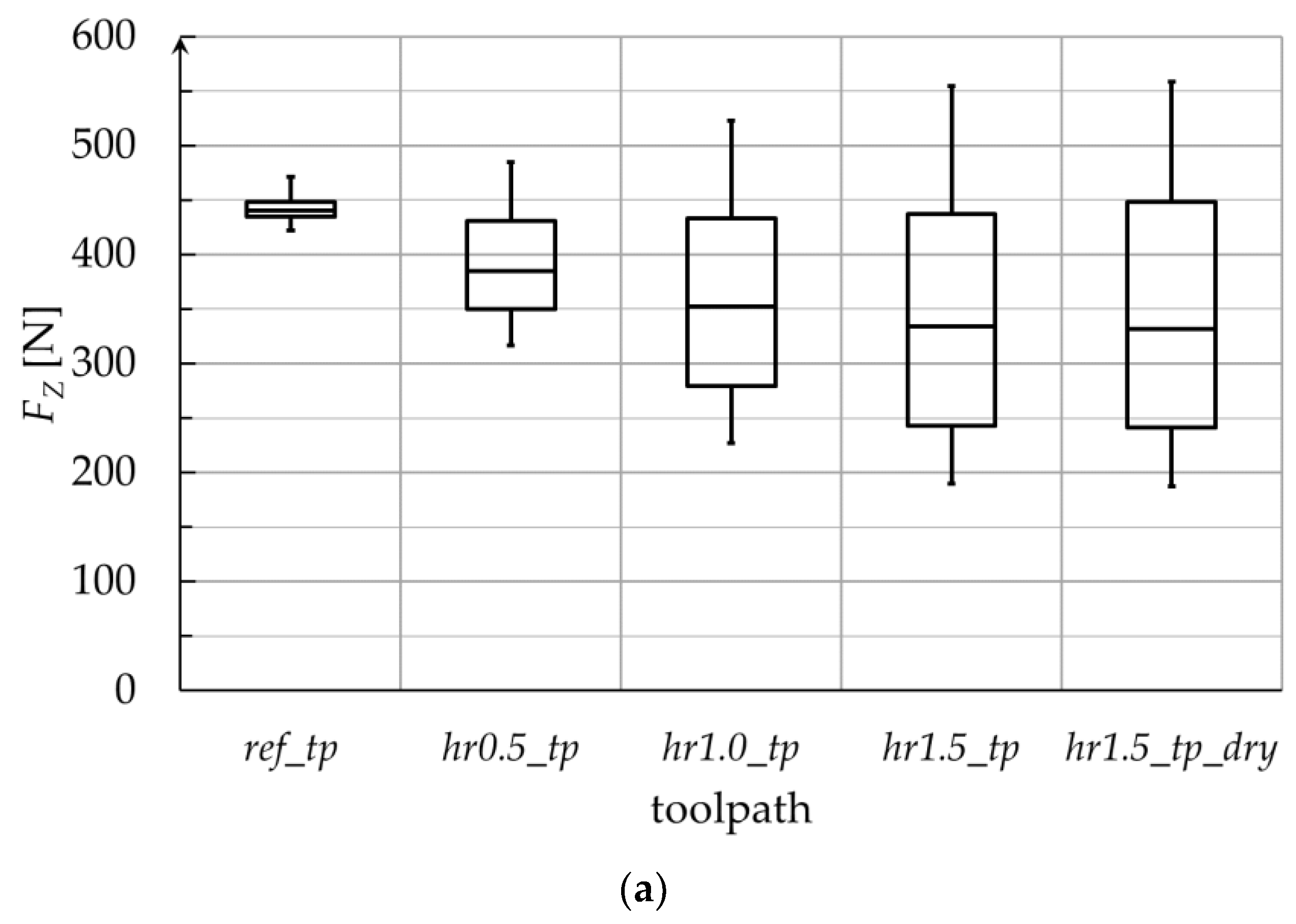
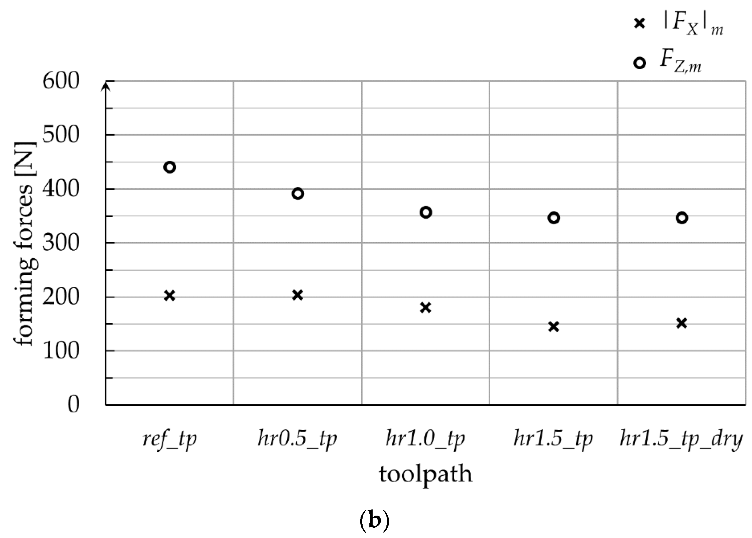

Table 1.
Forming times for the different toolpaths.
| Toolpath | Forming time [s] |
|---|---|
| ref_tp | 200.5 |
| hr0.5_tp | 241 |
| hr1.0_tp | 286.5 |
| hr1.5_tp | 337.5 |
Table 2.
Twist angles for the different toolpaths.
| Toolpath | Twist angle [°] |
|---|---|
| ref_tp | 7.0 |
| hr0.5_tp | 6.9 |
| hr1.0_tp | 6.6 |
| hr1.5_tp | 6.1 |
| hr1.5_tp_dry | 6.2 |
Disclaimer/Publisher’s Note: The statements, opinions and data contained in all publications are solely those of the individual author(s) and contributor(s) and not of MDPI and/or the editor(s). MDPI and/or the editor(s) disclaim responsibility for any injury to people or property resulting from any ideas, methods, instructions or products referred to in the content. |
© 2024 by the authors. Licensee MDPI, Basel, Switzerland. This article is an open access article distributed under the terms and conditions of the Creative Commons Attribution (CC BY) license (https://creativecommons.org/licenses/by/4.0/).
Copyright: This open access article is published under a Creative Commons CC BY 4.0 license, which permit the free download, distribution, and reuse, provided that the author and preprint are cited in any reuse.


