Submitted:
11 March 2024
Posted:
12 March 2024
You are already at the latest version
Abstract
The study of the tribological behavior of the braking system in auto vehicles requires knowing the characteristics of the material in contact and, in the work process, for the friction pair, brake disc-pads. Materials structural analysis is necessary because the wear process depends on the friction pair chemical composition, and brake disk-pads, respectively on the work process parameters (pressing force, rotational speed, traffic conditions, etc.). The material of the brake discs is generally the same gray cast iron, but the brake pads can be semi-metallic (particles of steel, copper, brass, and graphite, all united with a special resin), organic materials (particles of rubber, glass, and kevlar all joined with the help of a resin), composite materials that contain different constituents and ceramic materials (rarely have small copper particles). Therefore, the purpose of the paper is to know the crystalline structure and the mechanical properties of the brake pad materials, through specific studies and analyses, with important implications on the friction and wear behavior.
Keywords:
Brake pads
; Crystalline structure
; Tribological properties
; Braking system
1. Introduction
Evolution in time of the braking systems has meant continuous improvement to be efficient and reliable [1]. The main function of the brake is the speed control, and the deceleration rate of a vehicle is defined by energy dissipation.
Main objective of the braking system study is to improve its performance to ensure a safe, stable braking, in any situations/conditions. This improving, is also brought by the structural changes in the materials of the disc-brake pads pair due to the problems that appear in the braking system (creak, noise, and vibrations).
These problems can be solved by decreasing the friction coefficient (COF) but with it is decreases also the performance of the braking system [2]. These aspects encountered in the braking system are a problem for the automotive industry and for passengers, being essential in the design stage of a braking system.
Studies have been made considering different uncertain parameters, such as the coefficient of friction and other constructive parameters of the braking system. To avoid as much as possible the problems of creak, noise, and vibrations, these parameters assume structural modifications in the brake disc-pads pair. In this way, due to the influence of structural changes, it was necessary information obtaining for the optimal choice of the friction pair materials, to ensure the performance and stability of the braking system [3].
Based on previous experiences it is necessary to develop new friction materials and test their characteristics not to repeat the same disadvantages in their structure, but to obtain the total quality and reliability [4].
Many numerical simulations were performed at the contact interface (friction) interface of the disc material and brake pads, considering their predominant influence. At present, these contacts influence the phenomena of noise, creak, and vibrations, and therefore stability is not yet well understood [5]. Therefore, the braking system performance represents one aspect of improving the friction materials properties, in particular, those of the contact surfaces.
Thus, the brake screeching phenomenon was analyzed by Ganji and Ganji in ref. [6], considering the motion nonlinear equations due to large deformations and the revised of different material selection schemes, to find an optimized selection procedure [7]. Phatak and Kulkarni [8] achieved squeal reduction by structural modification and by studying the parameters affecting brake noise.
Shin [9] realized and experienced brake pads with the three-layer, first and third layers from plastic, and the middle layer from felt. Such pads reduce noise, improve the impact resistance of the brake pads, and ensure the braking system stability. Gao and Song [10] proposed the friction material for brake pads to be obtained by the process of metal-based sintering because it improves adhesion, COF, and wear resistance. This transformation supposes that structural changes can obtain the brake pads with varying stiffness and damping.
This process can improve the braking system stability and can reduce noise and vibration when braking, but its dynamics remain unclear. Instead, Wei, et al. al. [11] proposed the braking pads with two-layer (one basic and another friction) by simplifying the three-layer ones.
To produce the braking force, the friction layer is in contact with the brake disc, while the base layer plays the role of support. By optimizing the brake pad parameters, the chaotic vibrations were reduced [12], and hence the braking system stability was improved.
The experiments regarding the wear behavior of the brake pads must be preceded by metallographic [8,9], chemical [10], and even mechanical analyses [11,12] of the materials in contact. It is mentioned that the wear process depends on both the brake pad material and the disc material together with the working process parameters (pressing force, traffic conditions, rotational speed, etc.).
These analyses are necessary because the wear process does not depend only on the brake pad material, but and the disc material, respectively the working process parameters.
Therefore, the aim of the paper is represented by the used materials' structural analysis (metallographic, chemical, but also mechanical) as well as tribological, especially, those for the contact surfaces (before experimental testing at wear) to obtain the experiments data necessary to improve the braking system, to extend its life, respectively to optimize its operation.
2. Materials and Methods
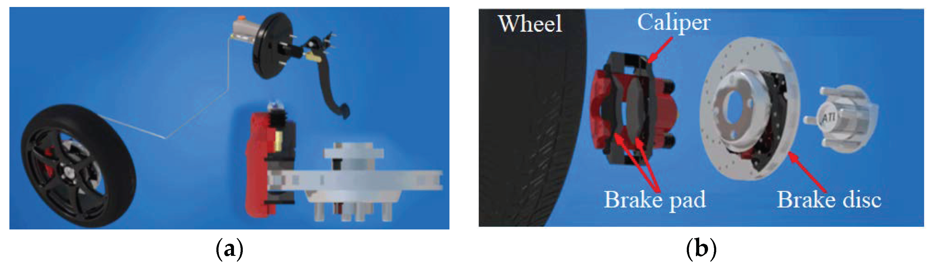
The main purpose of braking systems is to achieve the required braking torque, which causes the wheels to slow down and therefore brake. Today, most cars are equipped with the brake disc-pads system (Figure 1a) both on the front axle and also on the rear axle.
The braking system is a rotating cast iron disc rotated by the wheel hub and a bridge element, called a caliper, which is fixed on the axle housing, hub axle, or suspension bracket depending on the constructive version and it rides on the disc (Figure 1b). The caliper contains a of pistons and the brake pads pair, which by pressing the brake pedal lock the rotating disc, depending on the generated hydraulic pressure behind each piston and determines the speed reduction [13].
First, the samples were taken and prepared to perform the metallographic, chemical, and mechanical analyses in according with ref. [16]. Using a metallographic microscope (Olympus NTD Inc., USA) equipped with a camera and image processing software Stream Essentials, the metallographic analysis was possible on samples taken from the brake pad shown in Figure 2.
For this, brake pad samples were sectioned, using a Bosch Multi Wheel cutting machine with a disc of 76 x 10 x 1 mm manual actuation (Struers Inc., USA).
The samples from the brake pad and disc, to be handled and studied easily at the microscope were introduced in a resin matrix with a hardener and mixed in a special bowl. During mixing, a thin resin film is deposited on the material-sample surface (from the analyzed brake pads, Figure 3). To perform in optimal conditions the microscopic analysis was necessary to remove the resin film (Figure 4) by sanding and polishing, with the help of an automatic machine - Tegramin 25 (Struers Inc., USA).
Then, also with this machine (using the predefined program of it from the database), was operated sand and polishing the metallic-sample material from the brake pad (Figure 4), respectively of the sample from the brake disc material (Figure 5).
The final stage of the sample preparation is the metallographic attack having the role of highlighting the crystalline structure [16,17] of the brake pad material for the metallographic analysis. Thus, to make the crystalline structure components, the sample's polished surface is cleaned by washing with water, followed by drying and attacked with reagents, which dissolve or color them.
For reliable chemical characterization, energy dispersive X-ray spectroscopy (EDS) elemental mapping, is an analytical technique that allows the materials elemental chemical analysis/characterization. Then, to provoke X-ray emission the sample is excited by an energy source (for example, the electron microscope electron beam), and some of the absorbed energy is dissipated by ejecting core-shell electrons.
The information, regarding chemical composition can be obtained, down to the atomic level, by the EDS detector addition of (Olympus NTD Inc. USA), to the electron microscope. Then, a higher energy electron from the outer shell continues to fill its place, releasing in the form of an X-ray, the difference in energy, with a characteristic spectrum of its atom of origin. Exactly, this allows composition analysis of a sample volume, given and that has been excited by the energy source. Because characteristic X-rays are emitted and measured while the electron beam is scanned across the sample, each EDS spectrum is recorded and mapped to a specific position on the sample. Thus, the signal intensity corresponds to the element concentration, whereas the position of the peak in the spectrum identifies the element which will be seen in the next section.
The results quality depends on the signal strength and the spectrum clean. While signal strength allows particularly trace element detection and dose minimization and is based on a good signal-to-noise ratio; instead, the cleanliness will affect the spurious peaks number as a result of the materials that make up the electron beam.
The EDS spectrometer determines the material elemental composition, identifies the substance components, and quantifies the element's present amount [18].
Normally, the discs of vehicles are made of gray cast iron, while the brake pads of composite materials. The composite materials contain different constituents (sometimes 10 or more) and are compacted into a solid mass with a porosity of 5 - 10 %, by hot pressing. Although these friction materials have a wide range of compositions, they can be broadly classified according to Table 1 [19].
Composite materials are made by combining on a macroscopic scale, at least two constituents. The mechanical and chemical bonds that appear between the matrix and reinforcement of the composite give rise to a material whose properties are superior to the constituents taken separately. For this reason, the properties of composite materials are influenced by those of the constituent materials, by the volume fraction of the reinforcing component, by the orientation of the reinforcement in the composite, etc. [20].
The type of cast iron (with graphite flakes or spheres etc.), together with the metallographic composition, are very important because small or larger amounts of other elements (titanium or vanadium) strongly influence the performance at friction and wear or make it unusable [20].
For the tribological analysis of the composite materials with metallic constituents, depending on some parameters of the work process, a pin-on-disc tribometer was used. A gray cast iron ventilated brake disc with a diameter of 260 mm and a thickness of 22 mm was used as a disc, attached to the tribometer disc which can rotate at different speeds (in the case of the front 10, 12.5, and 15 m/s ). The pin was a cylindrical sample taken from a brake pad (made of ceramic metal material) with a diameter of 10 mm and a height of 10 mm, fixed in the arm of the tribometer and pressed on the disc with different loads (in the case of the front 2, 3, and 4 MPa).
3. Results and Discussions
The sliding contacts between the friction material of the pads and the brake discs decelerate the vehicle by dissipating its kinetic energy which slows the movement of the wheels. The slip between the disc and the brake pads is about half the vehicle speed. At the same time, the real contact area is typically between 15 and 20% of the pad’s total area [21].
The nature and disc surface characteristics together with the abrasive properties, composition, and brake pad microstructure determine the frictional behavior of the braking system [22]. It is mentioned that most friction materials for vehicle braking systems were designed and developed, considering that, the contact surface is with the cast iron. The structural performance of the composite materials is presented in Table 2.
Fiber length influences the mechanical properties of composites with fibers. To obtain an effective hardening and stiffening of the composite material requires a critical fiber length, which is 1 mm [23]. On the other hand, the fiber orientation in the composite material influences the hardness and mechanical properties [22]
The fiber alignment may be parallel to the long axes of the fibers in one direction, or they may have a disordered alignment. The alignment of the fibers leads to highly anisotropic properties in the composite, depending on the direction in which they are measured. Table 3 shows an illustration of the mechanical properties of the composite with metallic constituents for the brake pads (see Figure 2 and Figure 4).
It is worth noting that the resistance on the sliding surface in the perpendicular direction is much higher than that in the parallel direction. This is due to the contribution to the mechanical strength, of both the matrix and the fibers [22]. Thus, composite materials exhibit adequate mechanical properties and hence are suitable for use in braking systems. The characteristics of these materials are anisotropic due to the existence of the sliding surfaces of significant differences in the directions parallel and perpendicular (see Table 3). The cracks are always initiated in the matrix in bending strength tests and propagate in the fiber direction before the fiber bundles are finally pulled out. The exposed fibers, bear all the load, after the failure of the matrix, leading to the subsequent destruction of the composite. Therefore, in bending tests, the material shows a pseudo-plastic behavior, without a sudden drop in load. However, between different types of composite products, there are significant differences caused by the manufacturing process and depending on the final composition and porosity.
Therefore, it was considered of great importance to also know the metallographic and chemical structure of the material of the discs and brake pads used in the braking system of vehicles. Thus, the metallographic and chemical structure, together with the EDS spectrum were achieved on the samples taken from the material of a disc and a brake pad (see Figure 4 and Figure 5) and are presented below.
The metallographic structure of the brake disc material sample (magnified by 500:1, from the selected area) is presented in Figure 6. According to the chemical composition, it represents a pearlitic gray cast iron with: 3.34% C; 2.15% Si; 0.64% Mn; 0.03% P; 0.02% S; 0.04% Cr; 0.047% Cu; 0.041%, to which other chemical elements are added such as: Ni; Mo; Sn; V; Ti; W; Sb in very small amounts that cannot be detected, and the carbon equivalent (EC) ≈ 4.26.
The metallographic structure of the brake disc material (Figure 6a) contains pearlite (dark islands); secondary ledeburite (dotted white field); secondary cementite (white areas); fine lamellar graphite (dark lamellar islands), and in the EDS spectrum (Figure 6b) you can see the chemical elements that make up the chemical composition of the gray pearlitic cast iron. Overall, the structure of pearlitic gray cast iron is normal, being free of structural defects.
Of great importance is the metallographic and chemical structure of the brake pad material. Thus, the sample from the brake pad, according to the metallographic structure (magnified by 500:1, from the selected area) and the chemical composition is a metal composite with 10 % C; 9% O; 1% Na; 5% Mg; 6% Al; 12% Si; 7% S; 2% K; 14% Ca; 6% Ba; 2% V; 5% Cr; 2% Mn; 19 % Fe and shown in Figure 7.
Therefore, the metallographic structure of the brake pad material (Figure 7a) contains a lot of metal materials in significant proportions (51% in total), but also carbon in a proportion of 10% (that is, a metallic composite), and in the EDS spectrum, the chemical elements that make up the chemical composition of the metallic composite can be observed (Figure 7b). Overall, the structure of the metal composite is normal, and free of structural defects.
About the tribological analysis (the behavior of the analyzed materials during the friction and wear process [22]), the role of the metal in the composite friction materials was studied, without being correlated with a mechanism. The study focused on a non-asbestos formula where was introduced steel fibers (SF), brass (BF), and copper powder (CP). The total content was balanced with barite to keep the remaining components of the formula constant. The main effect of these metals (demonstrated by the tribological results) is to decrease the COF, due to increased speed, or load, and Figure 8 shows the effect of speed on the COF.
To determine the effect of velocity on various metal friction materials with mass/weight percent of 10 and 20 wt. %, respectively of their COF the pin-on-disc tribometer was used.
In the case shown in Figure 9, the material with the mass/weight percent 10 wt. % of metal (here copper (Cu)) had less wear than the reference material (metal-free, M0) under both load and speed testing conditions. Instead, the material with the mass/weight percent of 20 wt. % of Cu had double wear volume.
Compared to the SF, the C and its alloys show increased wear due to the higher metal content. In this regard, it should be remembered that the SF substantially improves the strength of the material. However, excessive heat transfer to the brake pad weakens the bond near the material surface, as pure Cu is a metal with a high thermal conductivity (401 Wm−1K−1) and this leads to greater material wear.
Comparing the surfaces by scanning with the electron microscope (Figure 10) of the materials M0, CP10, and CP20 shows morphological and topographical differences significant, which are correlated with the reduction of the COF and the rate of wear. However, since the wear debris is much smaller than in the other cases, where the wear rate is low, the plateaus are not very extensive.
In addition, it appears that the friction material microstructure covering the largest surface is almost intact, hence the binder continues to work. The material surface, M0 has a composite oxides large plateau and some detachments. Since the COF between oxide surfaces is usually lower than between metal surfaces, this extended oxide tribofilm is responsible for the decrease of the COF with increasing speed or load.
4. Conclusions
Friction materials play an important role in vehicle braking systems, traffic conditions, and road safety. For this, it is necessary to understand the causes of the structural properties modification, as well as the tribological phenomena characteristics (friction and wear).
Technical specifications of commercially available frictional materials present the tribological and mechanical properties, indications regarding temperature effects, and operating recommendations. The COF of frictional materials depends on their microstructure and composition and can only be evaluated by testing friction material.
By metallographic and chemical analysis of the brake pads, respectively the determination of their tribological and mechanical properties were solved some complex problems encountered in the braking system.
For a reliable chemical characterization, from the EDS analysis by elemental mapping, it was found the existence of chemical elements big number in the pad and disc material composition of the brake. Because, the material nature was not known, the metallographic attack has been used, to highlight the crystalline structure of this one. It was a normal structure without faults, of the pad and disc material of the brake.
A reliable chemical characterization, from the EDS analysis by elemental mapping, it was found the existence of a large number of chemical elements in the pad and disc material composition of the brake. Because the nature of the material was not known, the metallographic attack was used, to highlight the crystalline structure of this one. It was observed a normal structure without faults, of the pad and disc material of the brake.
For a complete analysis, some mechanical properties at the compression and bending stress were also measured, having a high resistance in a perpendicular direction in both cases. Also, the sliding resistance in the perpendicular direction is much bigger, than in the parallel direction. This is desirable because it gives the brake disc-pads couple good tribological behavior (high friction coefficient, minimal wear), and hence an extension of the life.
Tribological results showed that the main effect of metallic constituents from ceramic materials is to decrease the COF due to, on the one hand, the increase in percentage weight of metal, and on the other side, either due to increased speed, or load. Instead, the ceramic material with the lower percentage weight (10 wt.%) of the metal had less wear than the one metal-free, under both load and speed testing conditions, while the material with the greater percentage weight (20 wt.%) had double wear volume.
Further studies are needed on the braking systems to validate the microstructure and chemical composition, and the creation of new friction materials must be tested, to generate a database and maps of the friction zones.
Author Contributions
Conceptualization, F.I.; methodology, F.I., A-C.C.; software, A-C.C.; validation, F.I., A-C.C.; formal analysis, A-C.C.; investigation, F.I., A-C.C.; resources, F.I., A-C.C.; data curation, F.I., A-C.C.; writing—original draft preparation, F.I.; writing—review and editing, F.I.; visualization, A-C.C.; supervision, F.I.; project administration, F.I.; funding acquisition, F.I., A-C.C. All authors have read and agreed to the published version of the manuscript.
Funding
This research received no external funding.
Institutional Review Board Statement
Not applicable.
Informed Consent Statement
Not applicable.
Data Availability Statement
Data is contained within the article.
Acknowledgments
This work has been funded by the European social fund from the sectorial operational programmer human capital 2014-2020, through the financial agreement with the title "training of Ph.D. students and postdoctoral researchers to acquire applied research skills - smart", contract no. 13530/16.06.2022 - smis code: 153734.
Conflicts of Interest
The authors declare no conflict of interest.
References
- Post, W. Cap: Car braking systems, în book: Brakes, Brake Control and Driver Assistance Systems, Ed. Konrad Rief, Springer Vieweg ©Springer Fachmedien Wiesbaden 2014. [CrossRef]
- Siti, N.N.B.; Huhammad, M N.A.; Shahril, N.M.S.; Mohd, N.; Mohd, S.O. Cap: Analysis of Drum Brake System for Improvement of Braking Performance, in book: Engineering Applications for New Materials and Technologies, Ed. Springer International Publishing 2018, pp. 345–357. [CrossRef]
- Denimal, E.; Sinou, J.-J.; Nacivet, S. Influence of structural modifications of automotive brake systems for squeal events with kriging meta-modelling method. J. Sound Vib. 2019, 463, 114938. [Google Scholar] [CrossRef]
- Borivoj, N.; K.ila, M.; Sanja, S.; Marko, V.; Sladjana, B. The Importance of Application and Maintenance of Braking System in Modern Automobile, VI International Conference Industrial Engineering and Environmental Protection, Zrenjanin, Serbia, 2016.
- Denimal, E.; Sinou, J.-J.; Nacivet, S.; Nechak, L. Squeal analysis based on the effect and determination of the most influential contacts between the different components of an automotive brake system. Int. J. Mech. Sci. 2018, 151, 192–213. [Google Scholar] [CrossRef]
- Ganji, H.F.; Ganji, D.D. Effects of equilibrium point displacement in limit cycle oscillation amplitude, critical frequency and prediction of critical input angular velocity in minimal brake system. AIP Adv. 2017, 7. [Google Scholar] [CrossRef]
- Ebrahimi-Nejad, S.; Kheybari, M. Brake System Design for Sports Cars using Digital Logic Method. International Journal of Automotive Engineering 2017, 7(4), 2570–2582. [Google Scholar] [CrossRef]
- A. Phatak and P., Kulkarni. Drum Brake Backplate Analysis and Design Modification to Control Squeal Noise. International Journal of Engineering Development and Research http//www.ijedr.org. 2017, 5(3), Article 1703131–920-928. [Google Scholar]
- Shin, K.; Brennan, M.; Oh, J.-E.; Harris, C. ANALYSIS OF DISC BRAKE NOISE USING A TWO-DEGREE-OF-FREEDOM MODEL. J. Sound Vib. 2002, 254, 837–848. [Google Scholar] [CrossRef]
- Gao, E.; Song, B.W. Process for producing metal base sintered friction sheet, CN1994628, 2007.
- Wei, D.; Song, J.; Nan, Y.; Zhu, W. Analysis of the stick-slip vibration of a new brake pad with double-layer structure in automobile brake system. Mech. Syst. Signal Process. 2018, 118, 305–316. [Google Scholar] [CrossRef]
- Talati, F.; Jalalifar, S. Analysis of heat conduction in a disk brake system. Heat Mass Transf. 2009, 45, 1047–1059. [Google Scholar] [CrossRef]
- Heisler, H. Advanced Vehicle Technology; Elsevier BV: Amsterdam, NX, Netherlands, 2002; ISBN 9780750651318. [Google Scholar]
- How to Differentiate Braking Systems in Automobiles? Available: https://drivinglife.net/differentiate-braking-systems-automobiles.
- Childs, P.R. Mechanical Design Engineering Handbook, Cap. 13: Clutches and Brakes, Butterworth-Heinemann is an imprint of Elsevier, 2014, pp. 513-564, https://www.sciencedirect.com/book/9780080977591/mechanical-design-engineering-handbook.
- Geels, K.; Fowler, D.; Kopp, W.-U.; Rückert, M. Metallographic and Materialographic Specimen Preparation, Light Microscopy, Image Analysis and Hardness Testing; ASTM International: W. Conshohoken, PA, United States, 2007; ISBN.
- Vander Voort, G.F. Metallography: Principles and Practice, ASM International, Materials Park, OH, 1999.
- Chang, M.T.; Suraneni, P.; Isgor, O.B.; Trejo, D.; Weiss, W.J. Using X-ray fluorescence to assess the chemical composition and resistivity of simulated cementitious pore solutions. Int. J. Adv. Eng. Sci. Appl. Math. 2017, 9, 136–143. [Google Scholar] [CrossRef]
- Ferro, P.; Borsato, T.; Bonollo, F.; Padovan, S. A Solidification Time-Based Method for Rapid Evaluation of the Mechanical Properties of Grey Iron Castings. Int. J. Met. 2018, 13, 845–852. [Google Scholar] [CrossRef]
- Nazari, K.; Tran, P.; Tan, P.; Ghazlan, A.; Ngo, T.D.; Xie, Y.M. Advanced manufacturing methods for ceramic and bioinspired ceramic composites: A review. Open Ceram. 2023, 15. [Google Scholar] [CrossRef]
- Hutchings, I.; Shipway, P. Cap. 9: Applications and case studies, in Tribology. Friction and Wear of Engineering Materials, 2nd Edition, Butterworth-Heineman is an imprint of Elsevier, 2017, pp. 303-352, ISBN: 9780081009109, https://www.elsevier.com/books-and-journalsA. Day, Cap. 5: Brake Design Analysis în Braking of Road Vehicles, Oxford: Butterworth-Heinemann, 2014, pp. 97-148, ISBN: 9780128100264.
- Ilie, F.; Cristescu, A.-C. Tribological Behavior of Friction Materials of a Disk-Brake Pad Braking System Affected by Structural Changes—A Review. Materials 2022, 15, 4745. [Google Scholar] [CrossRef] [PubMed]
- R.C. Dante, Cap. 3: Types of friction material formulas în Handbook of Friction Materials and their Applications, Woodhead Publishing, 2016, pp. 29-54, ISBN: 9780081006191.
Figure 2.
Brake pad: 1. material de frictiune; 2. strat intermediar; 3. adeziv; 4. cadru principal; 5. strat de amortizare.
Figure 2.
Brake pad: 1. material de frictiune; 2. strat intermediar; 3. adeziv; 4. cadru principal; 5. strat de amortizare.
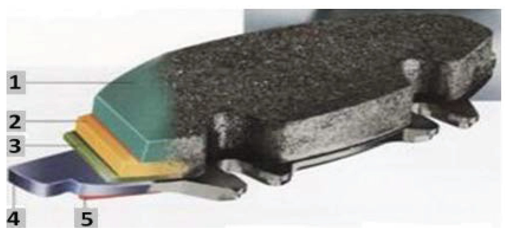
Figure 3.
Resin film over brake pad analysis area.
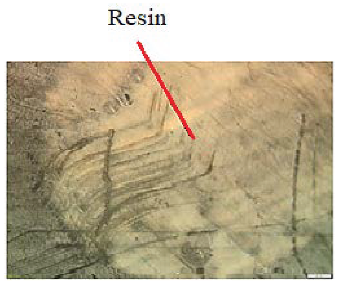
Figure 4.
Removal of the resin layer.
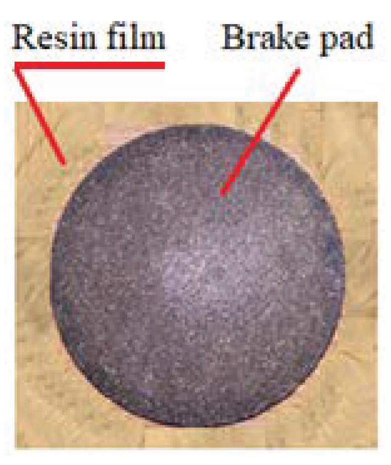
Figure 5.
Brake disc sample polishing.
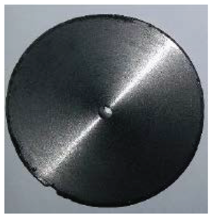
Figure 6.
Metallographic structure of the brake disc material (a); EDS spectrum of the delimited area (b).
Figure 6.
Metallographic structure of the brake disc material (a); EDS spectrum of the delimited area (b).
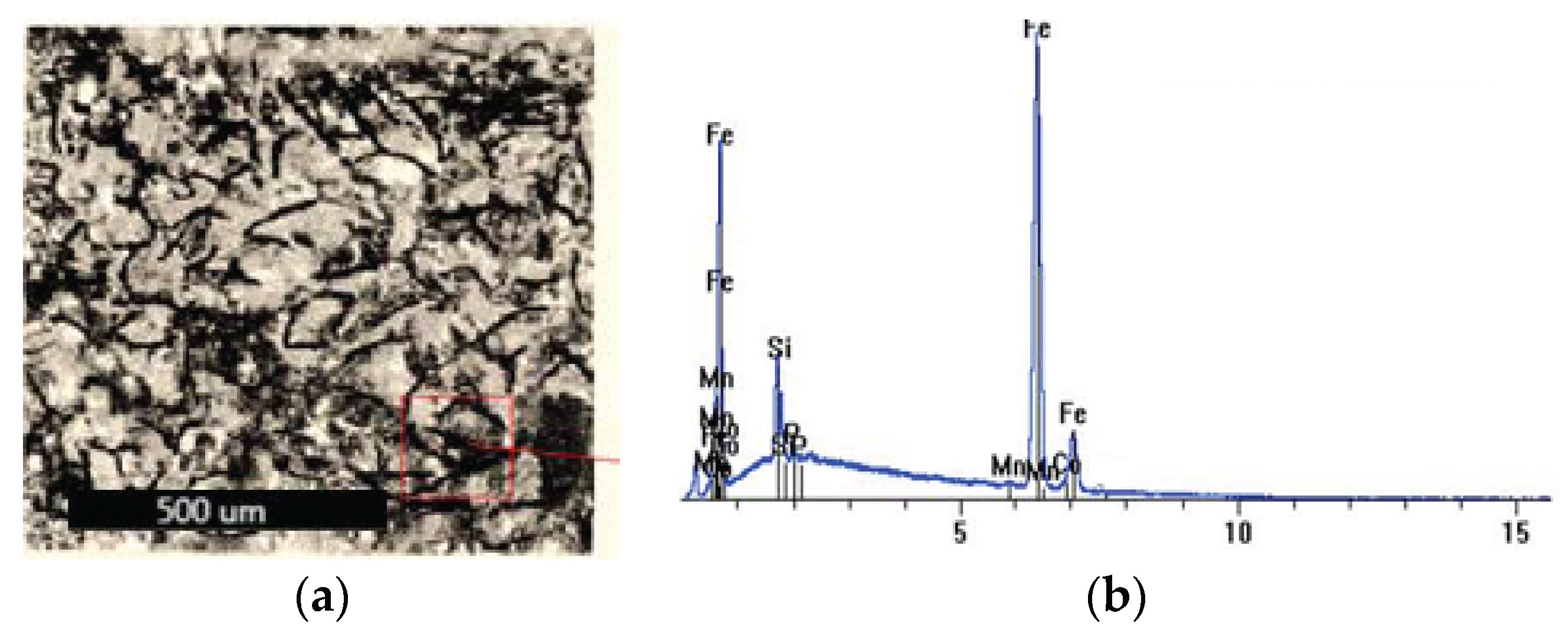
Figure 7.
Brake pad material metallographic structure (a); EDS spectrum of the delimited area (b).
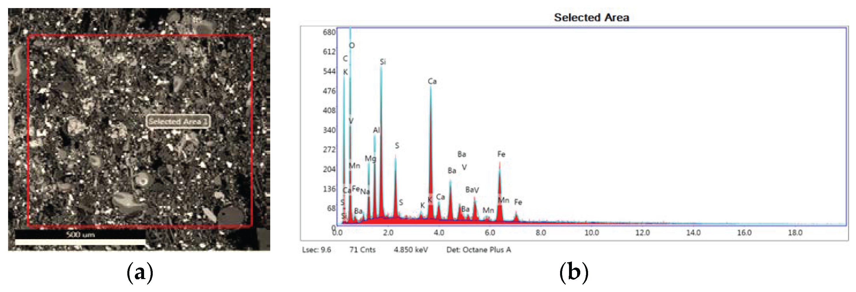
Figure 8.
Effect of velocity on the COF of various metallic friction materials with 10 wt. % (a) and 20 wt. % (b): M0 - metal-free reference material; SF - steel fiber; BF - brass fiber; CP - copper powder. Index 10 si 20 represents the metal amount, in the percentage weight (10 wt. % and 20 wt. %).
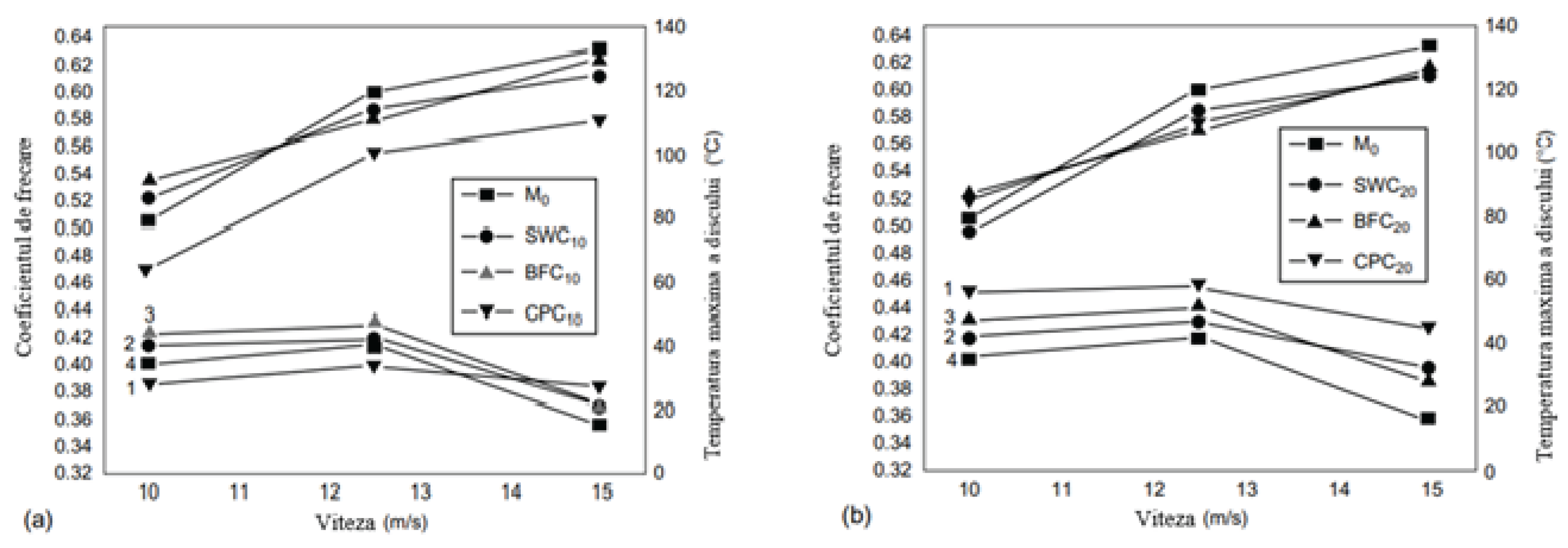
Figure 9.
Cumulative wear behavior of composite materials by two test methods, depending on the speed sensitivity of 10.0, 12.5, and 15.0 m/s, respectively the load sensitivity for 2, 3, and 4 MPa; at the speed of 12.5 m/s, the load capacity is 3 MPa.
Figure 9.
Cumulative wear behavior of composite materials by two test methods, depending on the speed sensitivity of 10.0, 12.5, and 15.0 m/s, respectively the load sensitivity for 2, 3, and 4 MPa; at the speed of 12.5 m/s, the load capacity is 3 MPa.
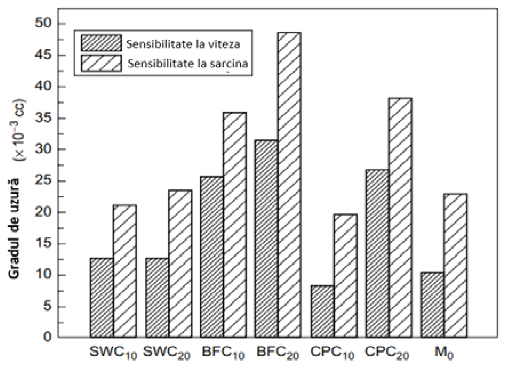
Figure 10.
SEM images: (a) CP10 (low wear and discoloration), (b) M0 (high discoloration), and (c) CP20 (high wear, low discoloration).
Figure 10.
SEM images: (a) CP10 (low wear and discoloration), (b) M0 (high discoloration), and (c) CP20 (high wear, low discoloration).
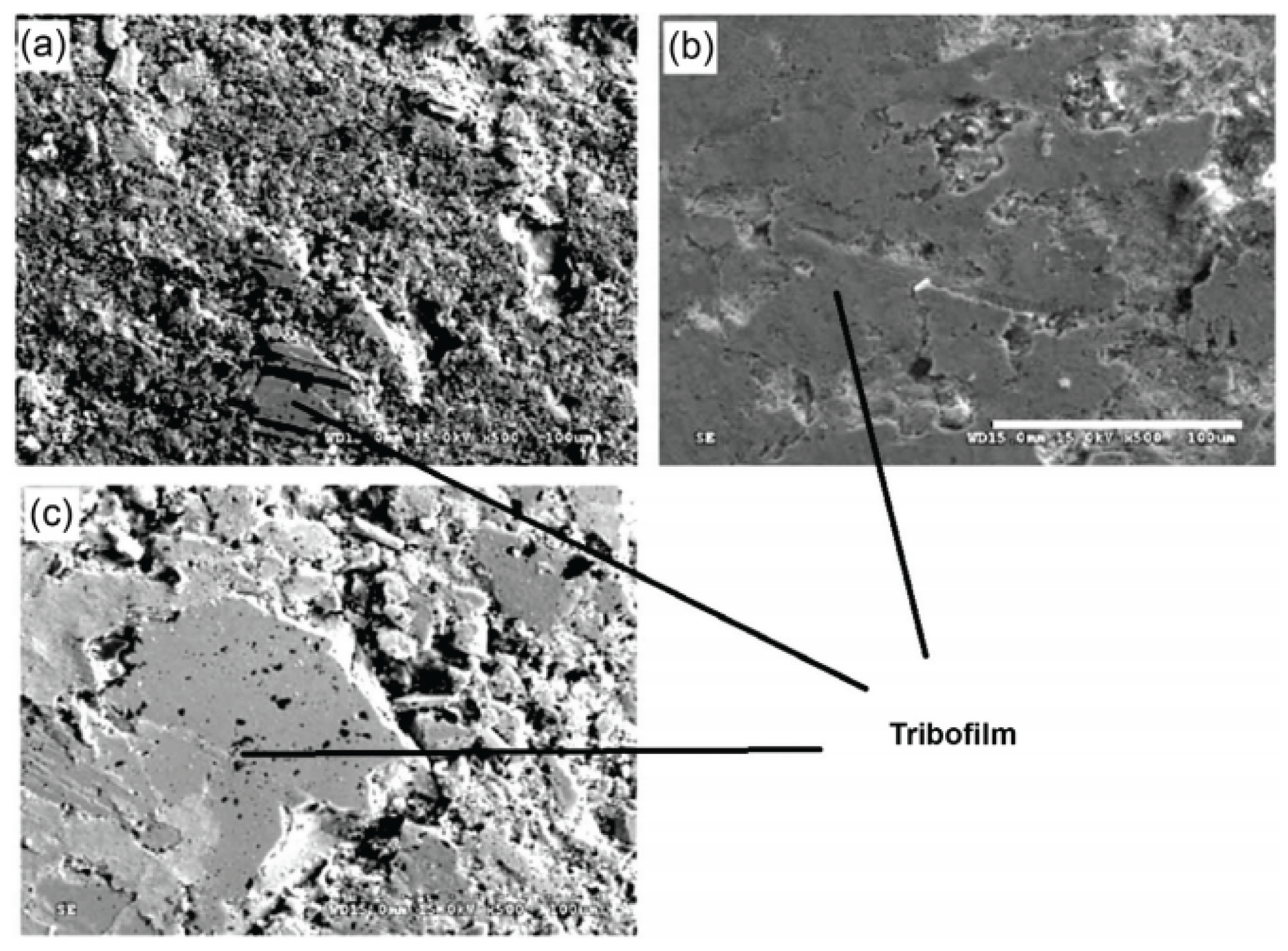

Table 1.
Component elements of brake pads.
| Description | Function | Example |
|---|---|---|
| Binder | Forms a thermally stable matrix | Thermosetting phenolic resin |
| Fibers | Provides mechanical properties | Brass, steel, kevlar, glass, ceramic |
| Lubricant | Stabilizes friction, especially at high temperatures | Graphite, metal sulphides |
| Abrasive | Cleans disc surface film and improves friction | Alumina, zirconium, metal silicates, chromium oxide, |
| Filler | Improves production and reduces costs | Barium sulfate, mica, vermiculite |
Table 2.
Structural performance of composite materials.
| Property | Material | |||
|---|---|---|---|---|
| Metal | Ceramic | Polymer | ||
| Volume | Fiber | |||
| Tensile strength | G | P | V | G |
| Rigidity | VG | V | VG | P |
| Shock resistance | G | P | V | G |
| Elongation | G | P | VG | V |
| Hardness | G | G | G | P |
| Dimensional stability | G | V | G | P |
| Thermal stability | V | G | VG | P |
| Density | P | G | G | VG |
| Corrosion resistance | P | V | V | G |
| Erosion resistance | G | G | G | P |
| Hygroscopic | V | V | V | G |
VG – very good; G – good; P – poor; V – variable.
Table 3.
Proprietăți mecanice ale compozitelor with metallic constituents for the brake pads.
| Bending strength | ┴ | 184±25 |
| ║ | 144±34 | |
| Compression strength | ┴ | 251±48 |
| ║ | 198±39 |
Disclaimer/Publisher’s Note: The statements, opinions and data contained in all publications are solely those of the individual author(s) and contributor(s) and not of MDPI and/or the editor(s). MDPI and/or the editor(s) disclaim responsibility for any injury to people or property resulting from any ideas, methods, instructions or products referred to in the content. |
© 2024 by the authors. Licensee MDPI, Basel, Switzerland. This article is an open access article distributed under the terms and conditions of the Creative Commons Attribution (CC BY) license (http://creativecommons.org/licenses/by/4.0/).
Copyright: This open access article is published under a Creative Commons CC BY 4.0 license, which permit the free download, distribution, and reuse, provided that the author and preprint are cited in any reuse.


