
Submitted:
27 February 2024
Posted:
28 February 2024
You are already at the latest version
Abstract
A novel concept of a finned piston system is presented and analyzed where the compression heat is continuously extracted from the compression chamber. The resulting compression characteristic moves in direction of an isothermal process, reducing so the temperature of the compressed fluid in the compression chamber and reducing the necessary mechanical work for the process. The finned piston concept consists in an integrated heat exchanger inside of the chamber and being constituated of imbricated flat fins placed on the stator part and on the mobile piston. The internal heat exchange surface is strongly increased in comparison with a classical piston/cylinder. The energetic performance of the new system is evaluated with the help of simulation. Pressures, forces and temperature of the compressed gas are simulated as well as the mechanical work needed. The different curves are compared with adiabatic and isothermal characteristics.
Keywords:
gas compression
; isothermal
; energy efficiency
; heat exchange
; finned piston
1. Introduction
In the context of the world situation of climate change and reducing the green gas emissions, many efforts are made for establishing new alternative sources. From photovoltaic plants to wind energy farms, high investments are made in the sense of replacing fossil-based solutions. As a possibility to bridge or compensate weather or seasonal fluctuations long term storage technologies will be based on an energy conversion into chemical carriers as hydrogen, synthetic gases or fuels. In such energy chains, gas compression stages will be used intensively and will have to be further developed showing higher energy efficiencies than today known industrial solutions.
Not only for new energy applications but also in many other industrial processes compression machines are used today as objects where energy efficiency issues have not been at the forefront of the technical developments. In a more general context improvements in the energetic performance of compression machines and other machines or processes will be part of the solutions of the energy transition. [1,2,3].
In this contribution, an original solution for the realization of compression stages is presented and analyzed. The new concept called the finned piston is based on the principle to export continuously the heat produced by the compression mechanism itself in order to reduce the amount of mechanical work needed for the elevation of the pressure following the reduction of the volume in the compression chamber. The concept of the finned piston corresponds in fact to have a heat exchanger integrated in the compression chamber. The new geometry proposed in the paper is following a previous study proposed by Mahbod Heidary in his PhD thesis [4,5,6]. The use of imbricated cylindric fins in the stator part of the cylinder as well as on the sliding piston increases significantly the convective heat exchange surface in comparison to a classic piston/cylinder assembly and allows a compression process with a reduced elevation of the temperature inside the compression chamber.
The principle of the finned piston is applied on a so-called gas booster used in many applications with low power and high pressure. When the original gas boosters use pneumatic actuators, well known for their very low efficiency, a first important step has been achieved by replacing it by a variable speed electric motor completed by an active compensator of the low frequency power fluctuations. Figure 1 shows the evolution of the gas booster from its original version with pneumatic motor (a) to the electromechanically moved versions. Two solutions are proposed, the first using a conventional crankshaft and piston rod (b), the second using a so-called Scotch Yoke mechanism (b) [7,8]. The next step for an increased efficiency is an improvement of the thermodynamic mechanism of the compression itself which tries to reach a characteristic of an isothermal compression.
2. The compression cylinder based on a finned piston
In comparison with a classical cylinder/piston assembly a so-called finned piston concept is built of imbricated metallic fins, with a first part at the stator side and a second one on the side of the sliding piston. The original system analyzed in [4,5,6] has used imbricated cylindric fins as represented at the bottom of Figure 2. One can see that such an architecture uses nearly the double space of a classical cylinder/piston system (top of Figure 2) when the volume occupied by the cooling fins is identical to the volume of the compression chamber. The gas is compressed in the spaces comprised between the stator fins, where the fins of the mobile part play the role of small pistons. The intake and exhaust path is given through the radial perforations from fin-to-fin, and via the outlet (O1 in Figure 2). On the other side (piston side), the gas is compressed in the spaces between the fins of the mobile part where the stator fins play the role of pistons. The intake and exhaust path is given at that side by radial perforations from fin-to-fin at the rear side of the piston fins and through an second outlet perforation placed at the top end (right side) of the stator fins (O2 in Figure 2). Anti-return valves in the intake and exhaust paths should be placed just after the orifices O1 and O2 in order to avoid excessive dead volumes. The gases of the two sides can then be mixed by a dedicated collector.
The system analyzed in this paper is built of imbricated flat fins as represented in the middle of the figure. The advantage of using flat fins instead of cylindric ones will be explained in the next section.
2.1. The heat exchange surface of the classic, flat and cylindric fin systems
The heat exchange surface of the different systems comprises the external surface of the global compression cylinder, the end and front surfaces of the stator and piston as also the effective side surface of each fin. A comparison of the three systems is given on the base of a specific system with the parameters given in Table 1.
2.1.1. Heat exchange surface of the classical cylinder
The convection surface of the classical cylinder – piston assembly is equal to the sum of the extrema surfaces and the external cylinder surface with
and
This surface varies in dependency of the piston’s position between 9826 mm2 and 1187mm2.
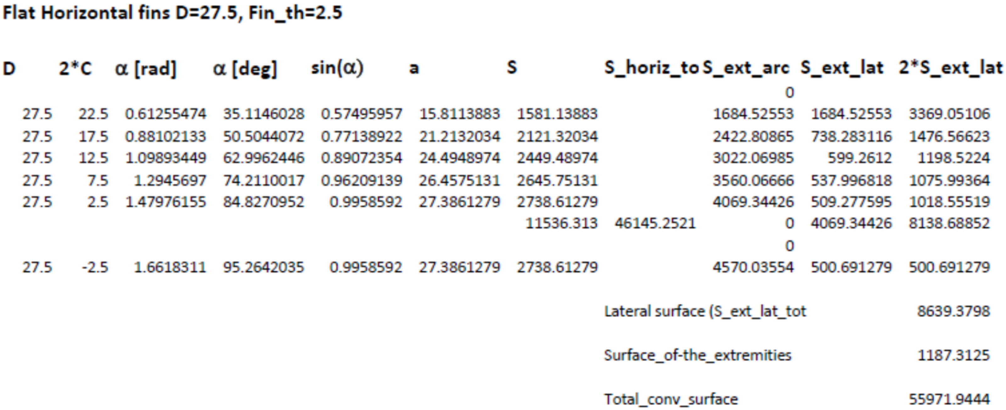
2.1.2. Heat exchange surface of the flat fin cylinder
This surface is calculated according to the representation of Figure 3.
The surface of a fin side is given by
where a is the fin’s width and l is the stroke of the piston in the cylinder
the angle α is
and the fin’s width
The 11 fins totalize a surface of 46145 mm2
To this surface, the front and rear surface must be added, namely given by (1), as well as the surface of the external cylinder from (2)
Finally, the total convection surface of the flat fin piston – cylinder assembly is
The details of the calculation are given in Appendix A.
2.1.3. Heat exchange surface of the cylindric fin cylinder
The convection surface of the cylindric fins system is calculated in Appendix B.
The external surface is equal to
2.1.4. Comparison of the different heat exchange surfaces
The heat exchange surfaces of the three solutions (classical, flat fins and cylindric fins) is represented in Figure 4 in dependency of the position of the piston.
Figure 4 shows an important property of the classical cylinder-piston where the heat exchange surface reaches its maximum value at the BDC (Bottom Dead Centre) position (corresponding to the 0 and 1 value of the dimensionless piston travel time of the cycle represented in the figure). The minimum value of the surface is given at the TDC (Top Dead Centre) position (corresponding to the 0.5 value of the dimensionless piston travel time in the figure).
For the finned pistons (flat fins and cylindric fins), the heat transfer surface is remaining constant and independent of the position of the piston since there is a gap between fins, and this allows the heat transfer to occur on the entire fin surface (Figure 4). However, the effective thermal resistance for the heat transfer from the compressed gas to the surrounding will be calculated in section 3.1.2 in dependency of the piston’s position.
3. Two models for the simulation of the finned piston
Two different methods can be applied for the evaluation of the performance of the compression cylinder. The first method is based on a common expression of the variation of the pressure resulting from the variation of the volume of the chamber:
For an implementation of this expression the volumetric ratio must be known what is relatively easy to define as a time function for representing the time variation of the pressure. The polytropic factor γ represents indirectly the quality of the thermal flow from the compressed gas to the surrounding but does not allow to make a relation to a thermal model based on classic parameters like the thermal capacity of the compressed gas, nor the thermal resistance which is easy to calculate on the base of the known parameters of the geometry of the finned system. For the evaluation of the temperature of the gas another expression can be used:
Again in this case the polytropic factor must be known, and it cannot be calculated from the parameters of a thermal model. With these formulas the evolution of the pressure and of the temperature can be drawn in dependency of the variation of the volume for the simple cases of adiabatic or isothermal compressions.
A second method which is based on the general expression can be used and can be implemented in the form of the structural diagram of Figure 5.
For this model, the temperature of the gas can be introduced as an output variable of a thermal model. Such a model is simply established on the base of two known parameters, namely the thermal capacity of the gas and a thermal resistance which defines the thermal flow to the external world. The input variable of the thermal model corresponds to the thermal power transmitted to the gas and is calculated from the piston’s velocity and the piston’s force. The mechanical power Pow exerted by the piston on the gas is supposed to be identic (friction is neglected) to the transmitted thermal power Pth as long as the exhaust valve of the cylinder is closed and no fluid in transferred out of the cylinder. The complete system model is represented in Figure 6 where the thermal equivalent scheme with capacitor Cth and resistance Rth are transformed in a structural diagram with the integration block (1/s). The output variable of the thermal model corresponds to the temperature of the gas and in the equivalent scheme corresponds to the voltage across the thermal capacitor Cth. The auxiliary (binary) variable X represents the opening/closing of the exhaust valve.
3.1. Parameters of the thermal model of the finned piston system
The energetic performance of the finned piston system will be evaluated with the help of a simulation of one compression stroke. First the evolution of the temperature of the gas will be simulated and second the necessary mechanical work needed for the compression will be calculated. These results will be obtained from the system model represented in Figure 6 where the parameters of the thermal model will play a significant role. The two parameters Cth and Rth will be calculated for the example defined through Table 1. They are based on the mass of gas compressed and of the variable thermal resistance of the exchange between the fins and within the interspace between fins in dependency of the piston’s position.
3.1.1. Thermal capacitance
The thermal capacitance Cth is expressed in and is calculated through rel. (12)
with the value of the mass of the gas m which is calculated from the filling conditions of the cylinder at a pressure of 15 bar and at ambient temperature
It comes
3.1.2. Thermal resistance.
The thermal resistance which defines the heat transfer from the heated gas to the surrounding results from the parallel connection of two resistances Rth1 and Rth2. Rth1 corresponds to the transfert in the space between fins (dominant when piston deployed, BDC). Rth2 corresponds to the gaps between the fins (dominant when the piston is retracted, TDC). The two resistances are represented in Figure 7.
The two resistances vary in function of the position of the piston and are calculated as:
A represents the value of the total heat exchange surface, namely the sum of the surface of the fins, added to the surface of the piston front and back, as also the surface of the outer wall. The factor α changes from zero to one depending on whether the piston is deployed or retracted.
H1 and H2 are the thermal transfer coefficients expressed in W/(m2*K)
where ka is the thermal conduction coefficient of the gas (air in the simulated case) expressed in W/(m*K). D1 and D2 are the distances between the fin walls as represented in Figure 7.
Finally, the value of the global Rth is obtained by the calculation of the parallel connection of Rth1 and Rth2, according to
Rth is represented in Figure 8 in function of the displacement of the piston in the cylinder
4. Simulation results
4.1. Simulation conditions
A finned piston-cylinder with flat fins as represented in the middle of Figure 2 is simulated in the time domain with the parameters given in Table 1. The simulation covers one half period of the cycle and corresponds to the compression stroke with a constant velocity of the piston. The simulation time is 0.5 second. The corresponding variation of the volume is represented in Figure 9.
The limitation of the volume at the TDC (Top Dead Centre) is made intentionally for avoiding the infinite value of the ratio in the simulation.
Figure 10 gives first a comparison of the two models used for the calculation of the pressure (Rel. (9) and Figure 5). The comparison is made for an isothermal compression. In this comparison the elevation of the pressure goes up to the limit imposed by the volume reduction limit. For the further simulations, the pressure is limited to a value of 160 bar which corresponds to the opening of the exhaust valve when the pressure of the gas in the cylinder equals the pressure in the receiving reservoir. The initial value of the pressure (intake) is of 15 bar. The curves of the two models are completely superposed.
4.2. Pressures, forces and temperatures
In Figure 11 three curves for the elevation of the pressure are given. First, the pressure elevation in adiabatic mode is shown, where the whole compression heat is maintained inside of the cylinder (blue curve). The initial condition is a value of 15 bar (15*109 N/m2). When the pressure reaches the value of the external reservoir (160 bar), an anti-return valve opens automatically and the remaining portion of the stroke occurs under this pressure value when the compressed gas is transferred. The second curve (yellow curve) corresponds to a model of the compression according to the diagram of Figure 6. The temperature of the gas is calculated with the help of a thermal model with the parameters of the thermal capacity of the gas and the variable value of the thermal resistance which was calculated in section 3.1.2. The curve shows a typically slower rise of the pressure due to the continuous evacuation of a part of the produced heat. The third curve (red curve) corresponds to an isothermal compression.
Figure 12 shows the variation of the force exerted by the piston on the gas. Again, the three conditions are represented, adiabatic (blue), finned piston (yellow) and isothermal (red).
In the simulation diagram of Figure 6, the mechanical power (Pow) and the power transmitted to the gas (Pth) are simulated. The evolution of these two variables are represented in Figure 12 and Figure 13. The mechanical powers are calculated from the mechanical force and the velocity of the piston. After opening of the exhaust valve, the power exerted by the piston serves to exhaust the gas and no more energy is transmitted to the gas in the cylinder. The opening of the valve is activated in the simulation diagram by the binary variable X.
Figure 14 represents the principal result of the study, namely the curves of the elevation of the temperature in the compression cylinder. The yellow curve shows the performance of the proposed system of the finned piston technology. The blue and the red curves represent the temperatures of the gas in the conditions of adiabatic and isothermal compression respectively. The performance of the integrated heat exchanger (the finned system) is particularly visible through the strong reduction of the elevation of the temperature (around 100 K instead of nearly 250 K in adiabatic conditions.
4.2.1. Effect of a reduced speed
Reducing the speed of the piston has the effect that the evacuation of the compression heat is more performant due to the fact the thermal time-constant in the thermal model (Cth and Rth) are not changed. The result is that the rise of the temperature in the cylinder is reduced. Figure 15 shows again the evolution of the temperature when the speed of the piston is reduced from 0.18 m/s to 0.09 m/s (Figure 15 a) and 0,045 m/s respectively (Figure 15 b). This means that the 90 mm stroke is covered in 1 and 2 s (instead of 0.5 s). The value of the temperature in adiabatic conditions is unchanged as well in isothermal conditions. For the finned piston system (yellow curve) the elevation of the temperature is one half of the elevation with the original speed (0.18 m/s). With a speed of 0.045 m/s the elevation is reduced another 50%.
4.3. Energetic considerations
Figure 16 is showing the performance of the finned piston system in terms of energy. The three curves correspond to the integration of the mechanical power needed to move the piston. It is effectively the energy consumed by the different compression tasks (adiabatic in blue, finned in yellow and isothermal in red). The reduction of the needed energy from 350 to 300 Joules corresponds to a saving of 14%.
In Figure 17 the energy transferred from the piston to the gas is represented. This energy comprises two parts, namely the energy transferred to the gas itself (gas internal energy) and a part which is evacuated by the fins.
4.3.1. Effect of a reduced speed
The mechanical work needed for the compression up to 160 bar is also reduced when the compression speed is reduced. Figure 18 shows the same variables as in Figure 16 but when the speed is reduced to 0.09 m/s (Figure 18 a) and 0.045 m/s (Figure 18 b) respectively. The final value of the work of the finned piston at t=1 s is 289 J for a piston speed of 0.09 m/s. The reduction from 350 J to 289 J represents a reduction of 17.4%. For a speed of 0.045 m/s (Figure 18 b) the curve of the work of the finned solution is even closer to the curve of the isothermal compression (final value: 279 J).
5. Discussion and future development
5.1. The limit of the model of the finned piston systems
The energetic performance of the finned piston concept has been evaluated by simulation on the base of a dedicated model which includes a thermal model for the cooling effect of the finned system. The gain on the necessary mechanical work for the compression has been evaluated in this first study. Additionally the elevation of the temperature and the mechanical work for compression have been simulated for a reduced speed of the piston. The verified performance of the proposed system with the simple model used in this study shows a good potential for a performance increase of a real system. However, the performance should be calculated more accurately, including for instance the friction of the mechanical parts, especially of the sealing elements. Particularly for high pressures the influence of the seals can be of importance.
All the simulated phenomena, and in the foreground the elevation of the temperature, are based on the assumption that the temperature of the fins and of the whole cylinder body is constant and identic to the ambient temperature. In reality the temperature of the fins will be dependent on the quality of their own cooling. In consequence the model should be completed by a part dedicated to the cooling of the stator fins and of the mobile fins. Such a model should include the resistance of the thermal conduction of the element between the compression fins and the fins of the stator and mobile cooling system. Also the thermal capacitance of the additional elements should be included.
5.2. A finned compressor with cooling of the stator and of the mobile finned piston
In Figure 19 a complete compressor with the finned technology is represented. The compressor consists of two cylinders using the finned technology. The two pistons are connected to a common crankshaft via two connecting rods, and they are working with 180° phase-shift. This phase-shift allows to get the same compression sequence of the two lateral cylinders of a classical gas booster shown in Figure 1.
The cooling of the stator part does not represent a big challenge due to its non-moving character. But concerning the sliding finned pistons the transfer of the heat is of different difficulty. The heat transfer functional elements are given by a couple of sliding horizontal fins, moving inside a cylinder prolongation section and are cooled by a transverse air flow. The air flow is produced by a dedicated fan.
For the sliding fins, they play two different roles, the first being to cool the piston at its rear side, and the second role is to transmit the compression force from the crankshaft to the mobile piston.
The proposed system of Figure 19 should be modelled accurately for an evaluation of its performance. A finite element representation of the thermodynamic phenomena will certainly produce the best results.
5. Conclusions
A new finned piston system has been analyzed for its energetic performance and for the reduction of the elevation of the temperature. The study with a dedicated model shows a good performance and significant reduction of the temperature in the compression cylinder. The simulation are made for different values of the compression speed.
Funding
This research received no external funding.
Appendix A
The convection surface of a 27.5 mm cylinder with 2.5 mm flat fins is calculated.
Appendix B
Calculation of the convection surface of the cylindric fins
| Cylindric fins | |||||
| D | 2*C | s_cyl | 2*s_cyl | ||
| 27.5 | 22.5 | 7065 | |||
| 27.5 | 17.5 | 5495 | |||
| 27.5 | 12.5 | 3925 | |||
| 27.5 | 7.5 | 2355 | |||
| 27.5 | 2.5 | 785 | |||
| 19625 | 39250 | ||||
| Surface of the cylinder fins | 39250 | ||||
| Surface of the external cylinder | 8639.379797 | ||||
| Surface of the extremities | 1187.3125 | ||||
| Total_conv_surface | 49076.6923 | ||||
References
- Haifei Tian et al. Advancements in compressed air engine technology and power system integration: A comprehensive review Energy Reviews 2 2023, 100050, Elsevier. [CrossRef]
- Amir Fazeli ⇑, Amir Khajepour, Cecile Devaud, A novel compression strategy for air hybrid engines, Applied Energy 88 (2011) 2955–2966, Elsevier.
- Rufer, A. Semi-Rotary and Linear Actuators for Compressed Air Energy Storage and Energy Efficient Pneumatic Applications, Bentham Science Publishers, 2023.
- Heidari Mahbod, Contribution to the technique of compressed air energy storage – The concept of finned piston, PhD thesis EPFL, Ecole Polytechnique Fédérale de Lausanne, Thesis No 6738 EPFL, (2015).
- Heidari Mahbod, Rufer Alfred, Thome John R., Thermo-Electric Analogy Method for Computing Transient Heat Transfer in a New Reciprocating Finned Piston Compressor, Proceedings of the 15th International Heat Transfer Conference, IHTC-15 August 10-15, 2014, Kyoto, Japan.
- Heidari Mahbod, Design, Modeling and Experimental Validation of a Novel Finned Reciprocating Compressor for Isothermal Compressed Air Energy Storage Applications, Energy 140(1):1252-1266, December 2017.
- Rufer A., Increasing the Energy Efficiency of Gas Boosters for Hydrogen Storage and for Refueling Stations, Energies 16(4) February 2023.
- Arakelian Vigen, Le Baron Jean-Paul, Mkrtchyan Manuk, Design of Scotch yoke mechanisms with improved driving dynamics, Proceedings of the Institution of Mechanical Engineers Part K Journal of Multi-body Dynamics, November 2015.
Figure 1.
Gas boosters driven by pneumatic motor a) and by electric motor b) and c).
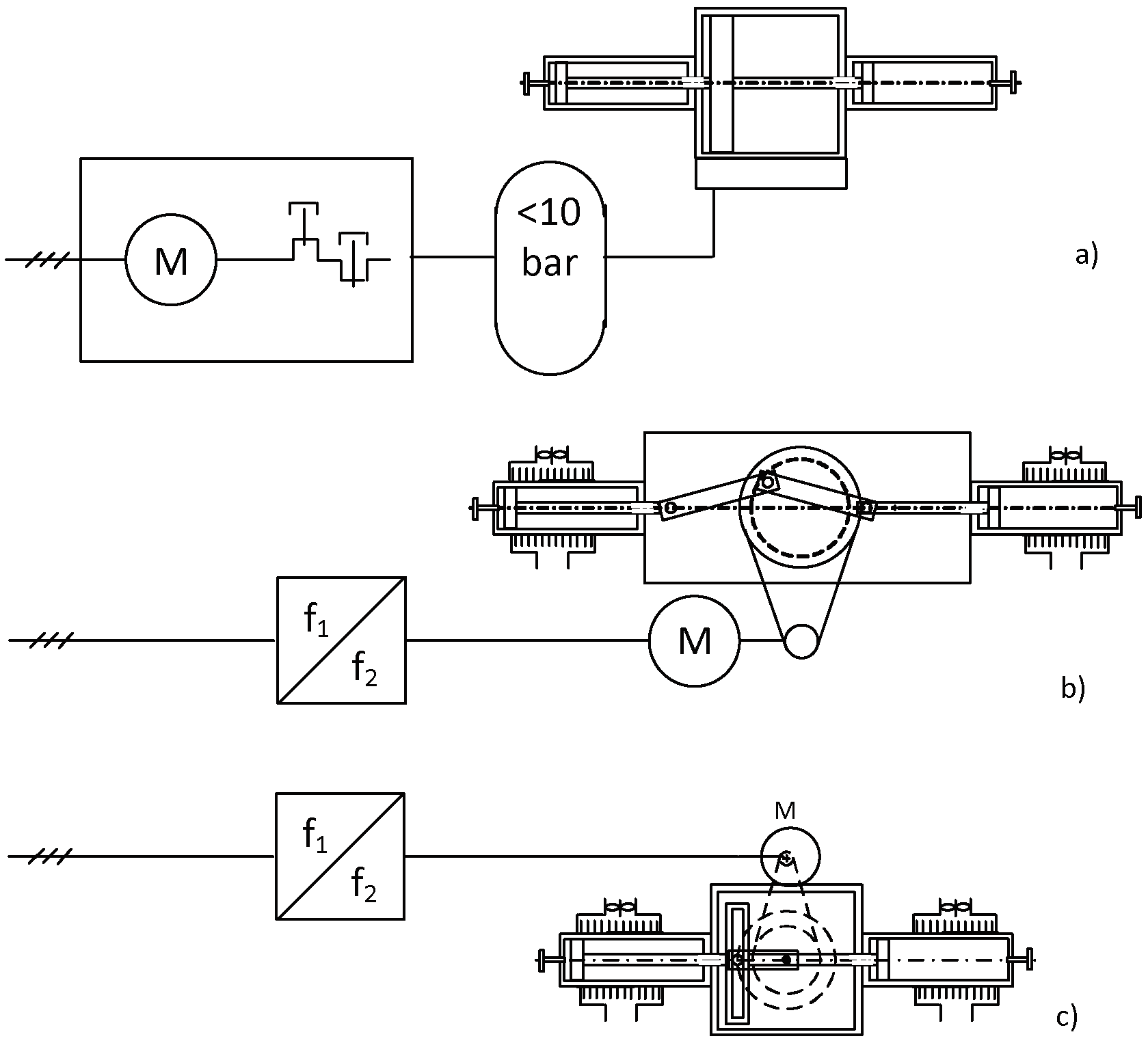
Figure 2.
Classic piston and finned pistons with flat and cylindric fins.
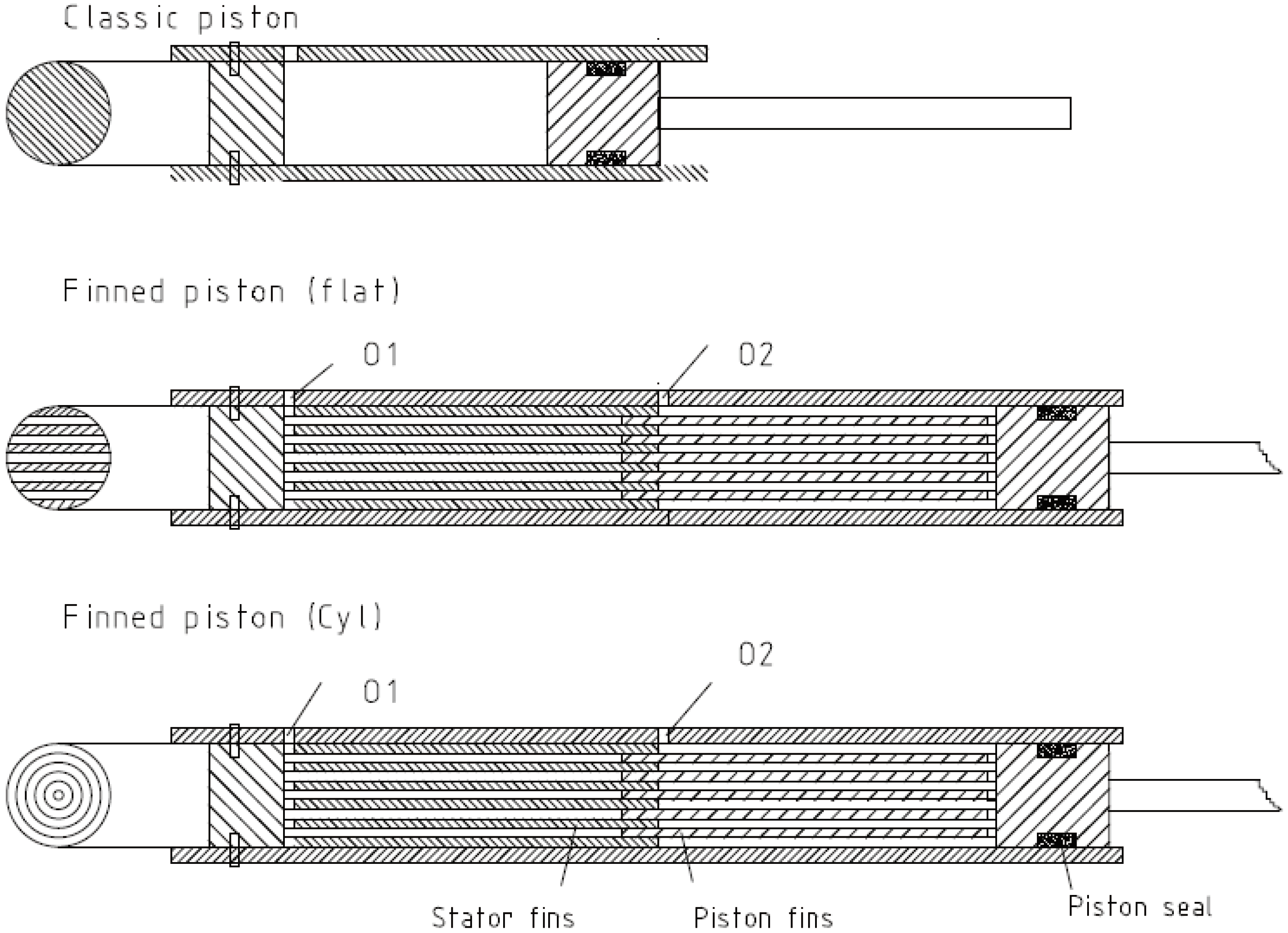
Figure 3.
Parameters of the flat fin cylinder.
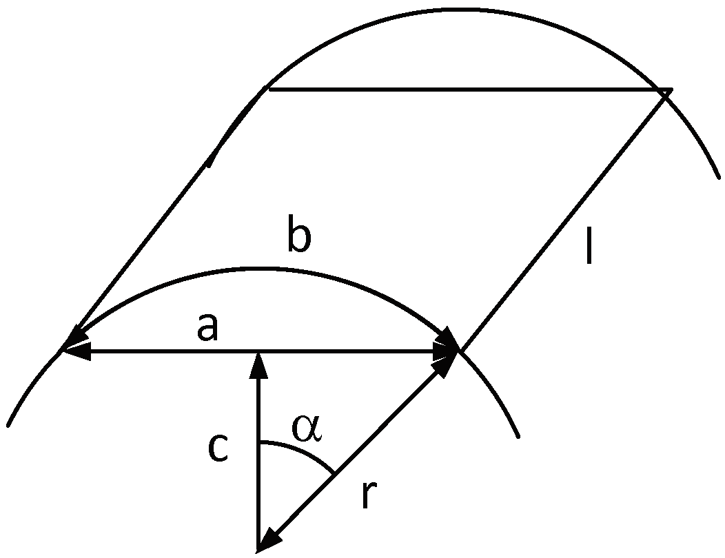
Figure 4.
Heat transfer areas of the different cylinders.
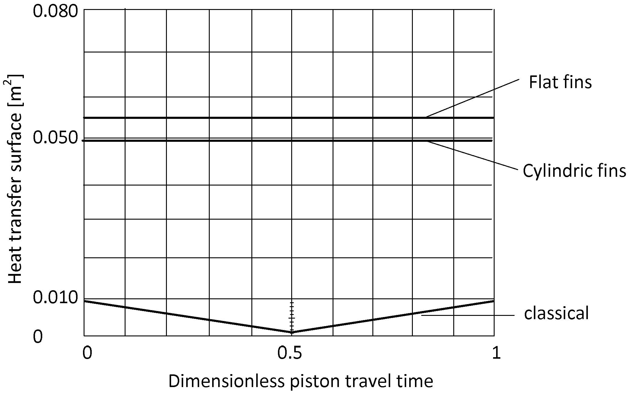
Figure 5.
Thermal model for the pressure.
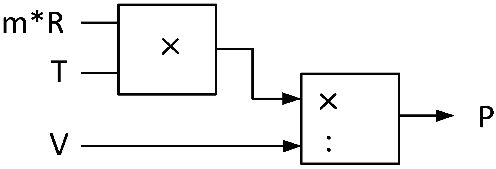
Figure 6.
The complete model for the compression cylinder with the thermal part.
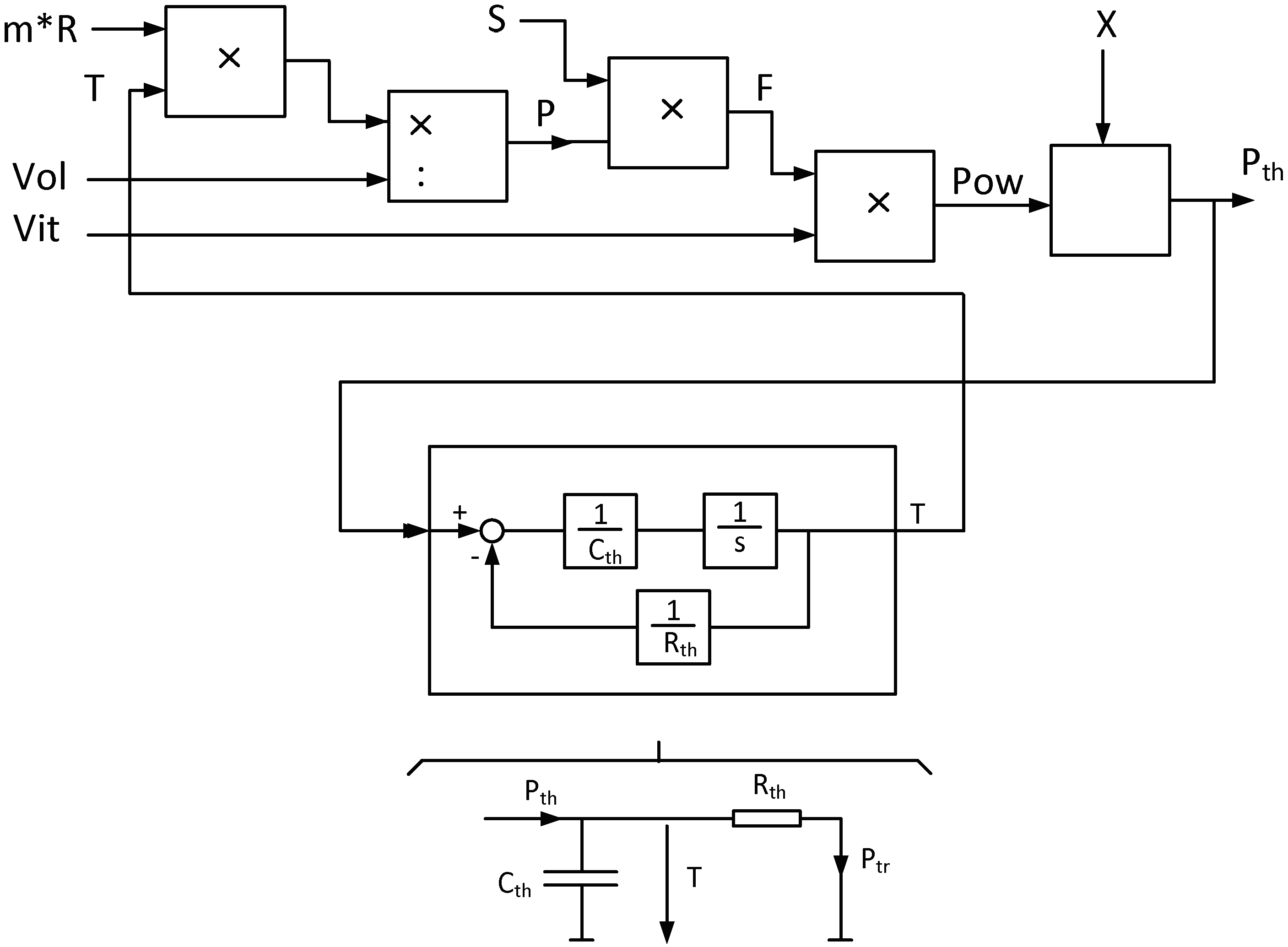
Figure 7.
Definition of the thermal resistances Rth1 et Rth2.
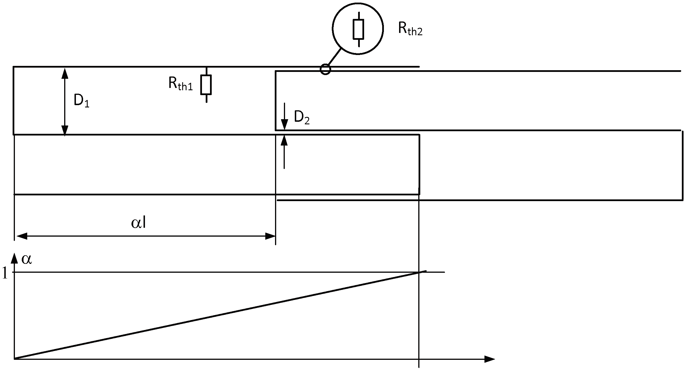
Figure 8.
Thermal resistance in function of the piston’s displacement.
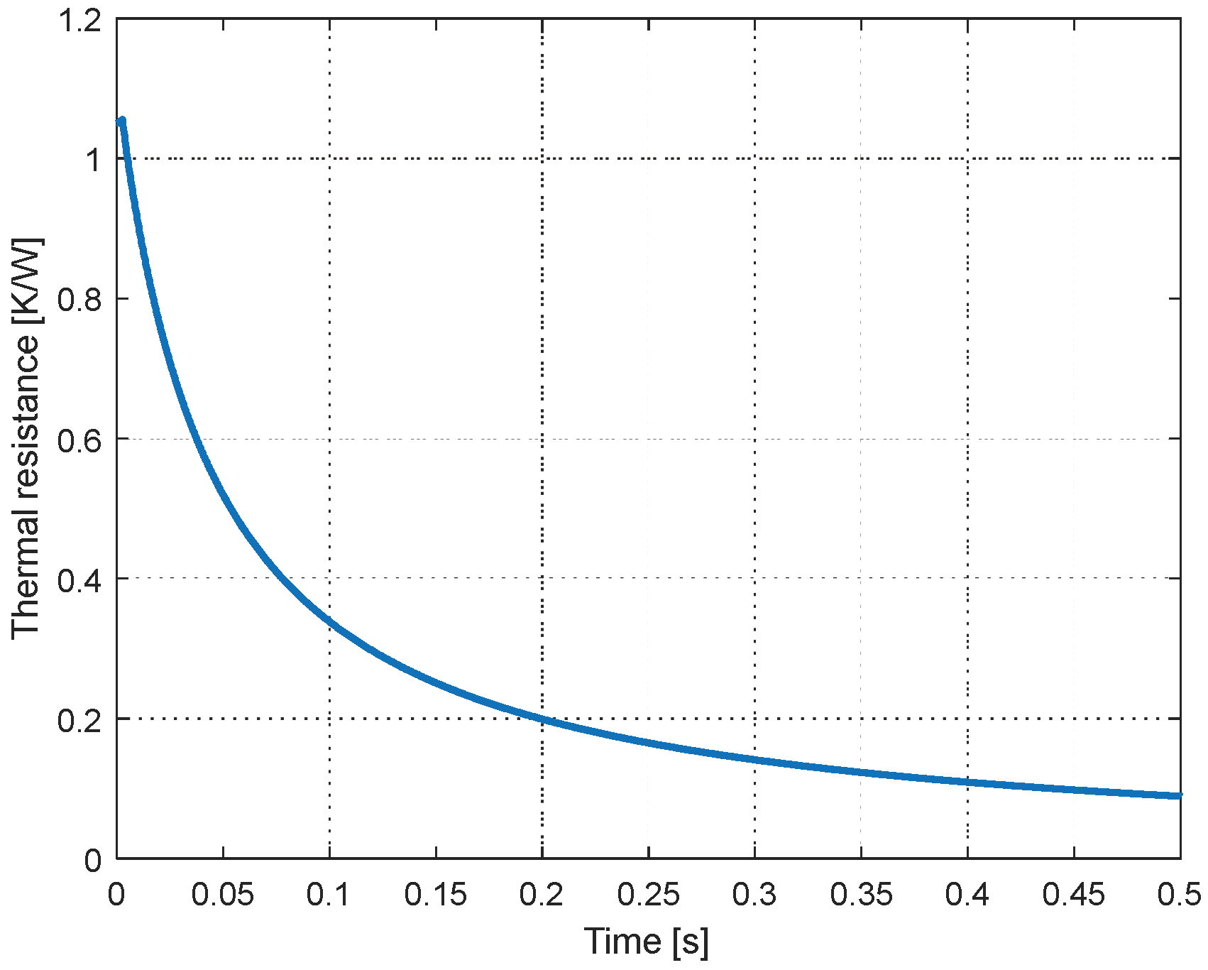
Figure 9.
Variation of the volume of the compession chamber.
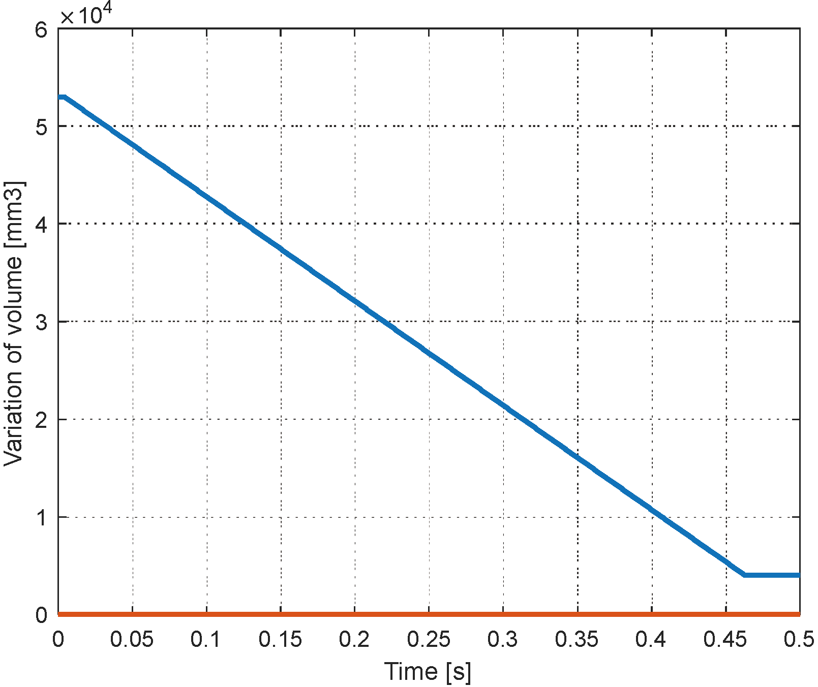
Figure 10.
Comparison of the models.
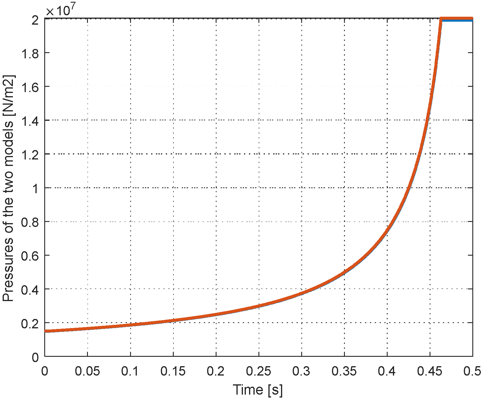
Figure 11.
Pressure during compression adiabatic, “real” and isothermal.
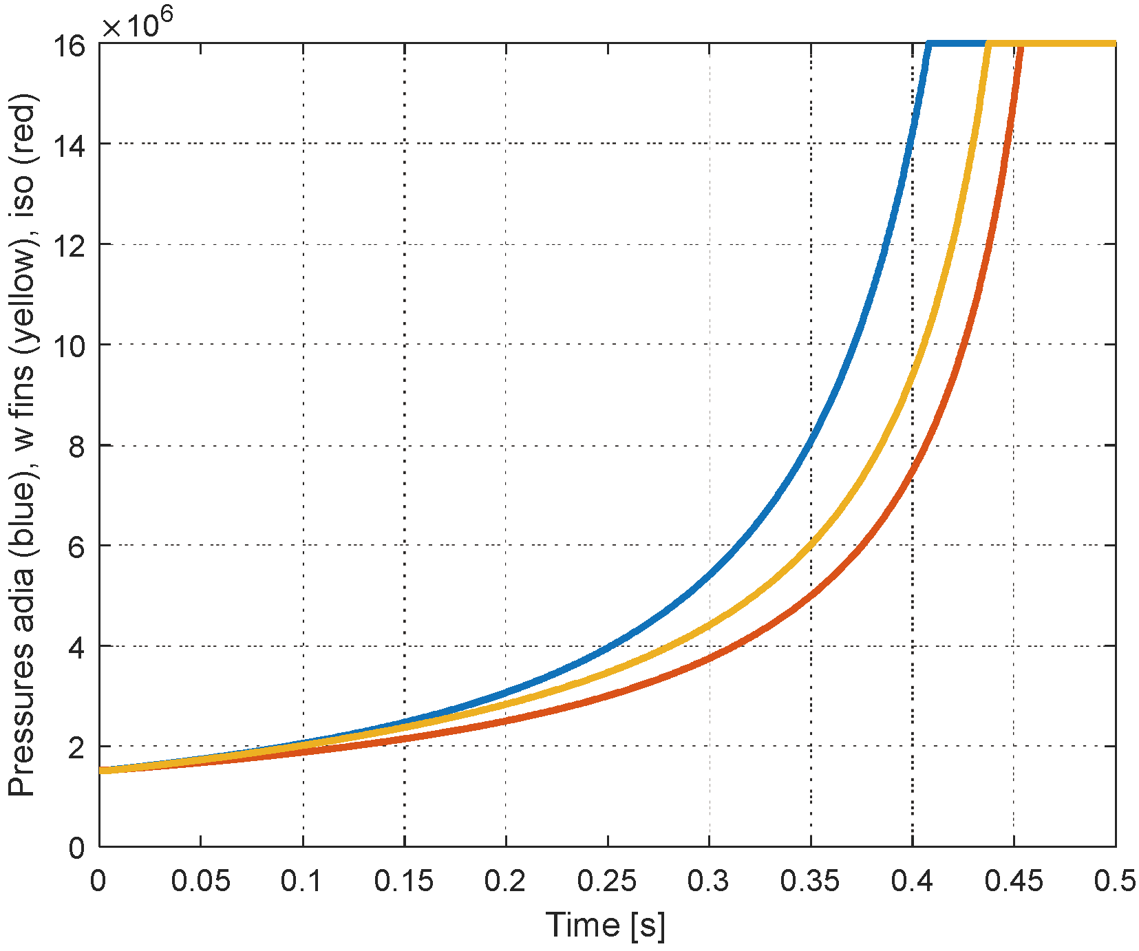
Figure 11.
Forces during compression adiabatic, finned and isothermal.
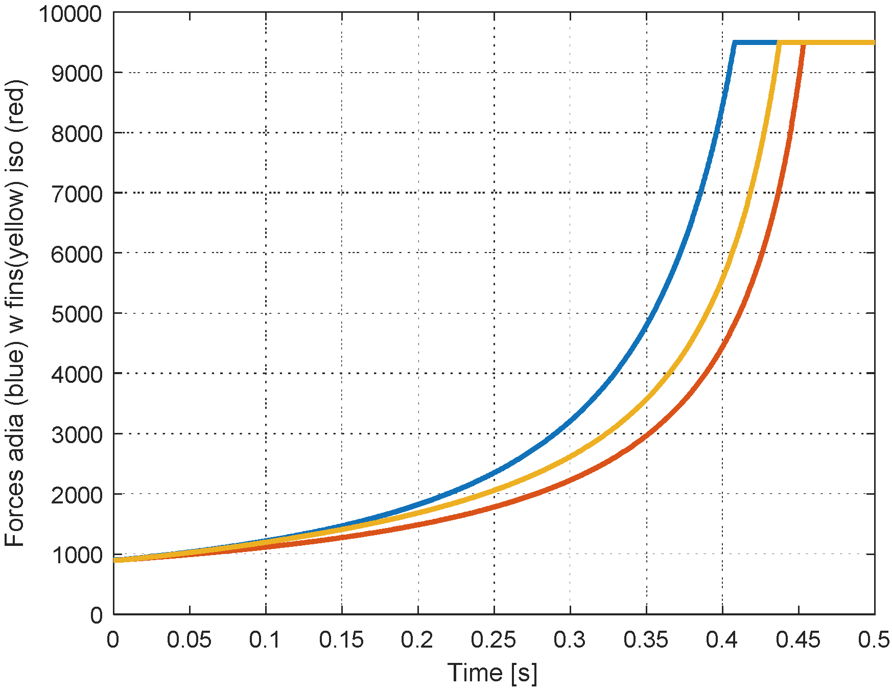
Figure 12.
Mechanical power needed by the piston.
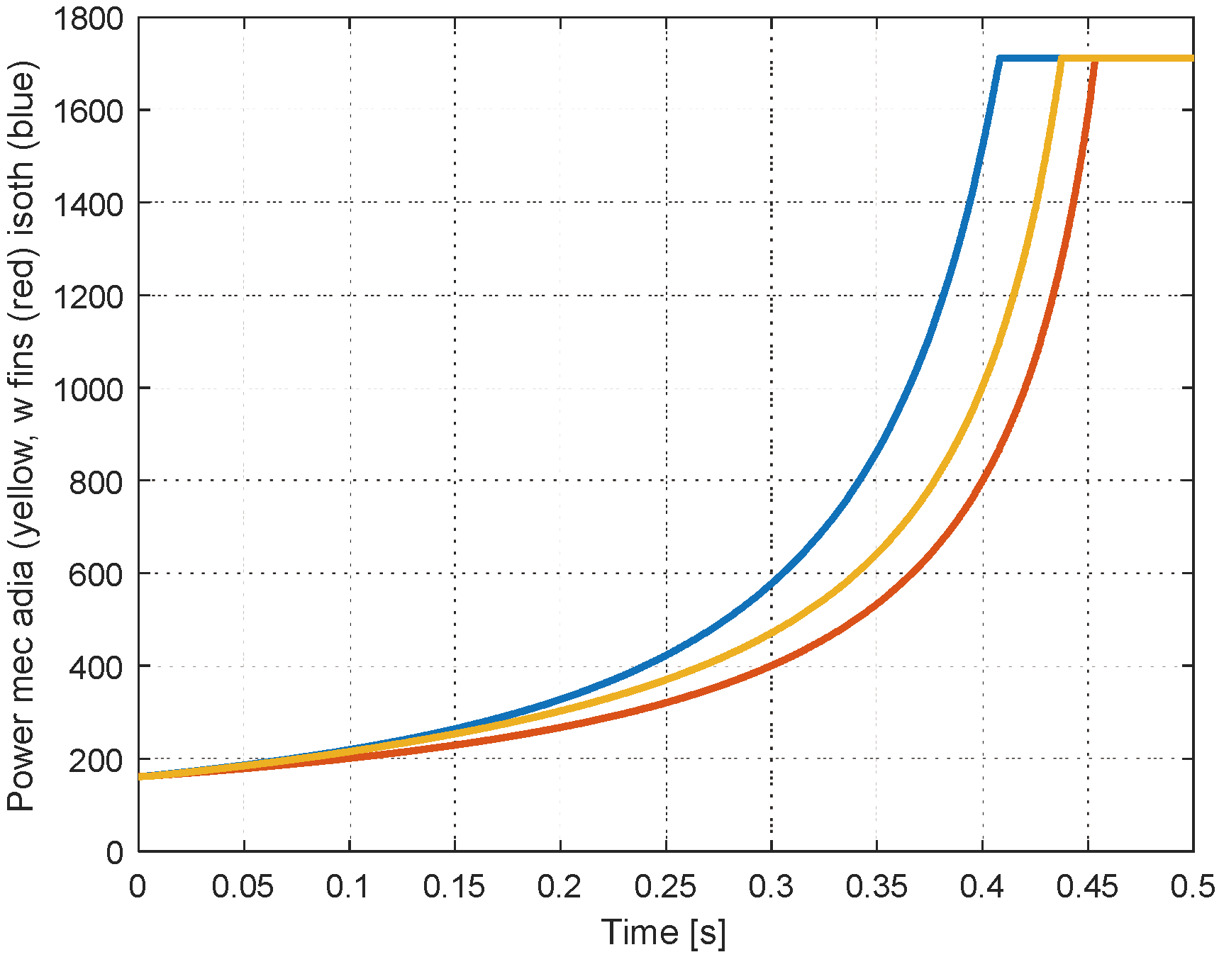
Figure 13.
Power transmitted to the gas.
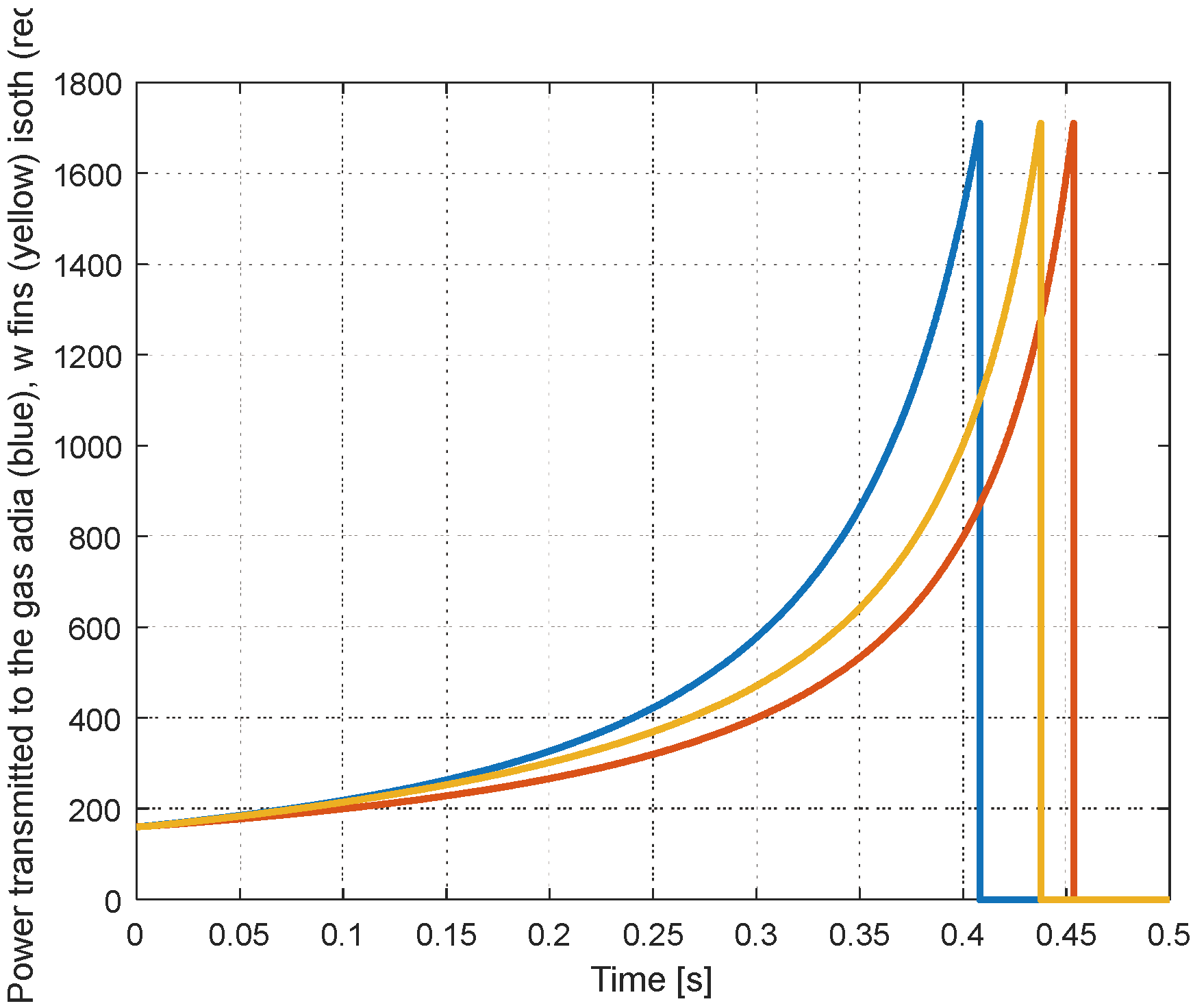
Figure 14.
Temperatures of the gas during compression, adiabatic (blue), finned (yellow) and isothermal (red).
Figure 14.
Temperatures of the gas during compression, adiabatic (blue), finned (yellow) and isothermal (red).
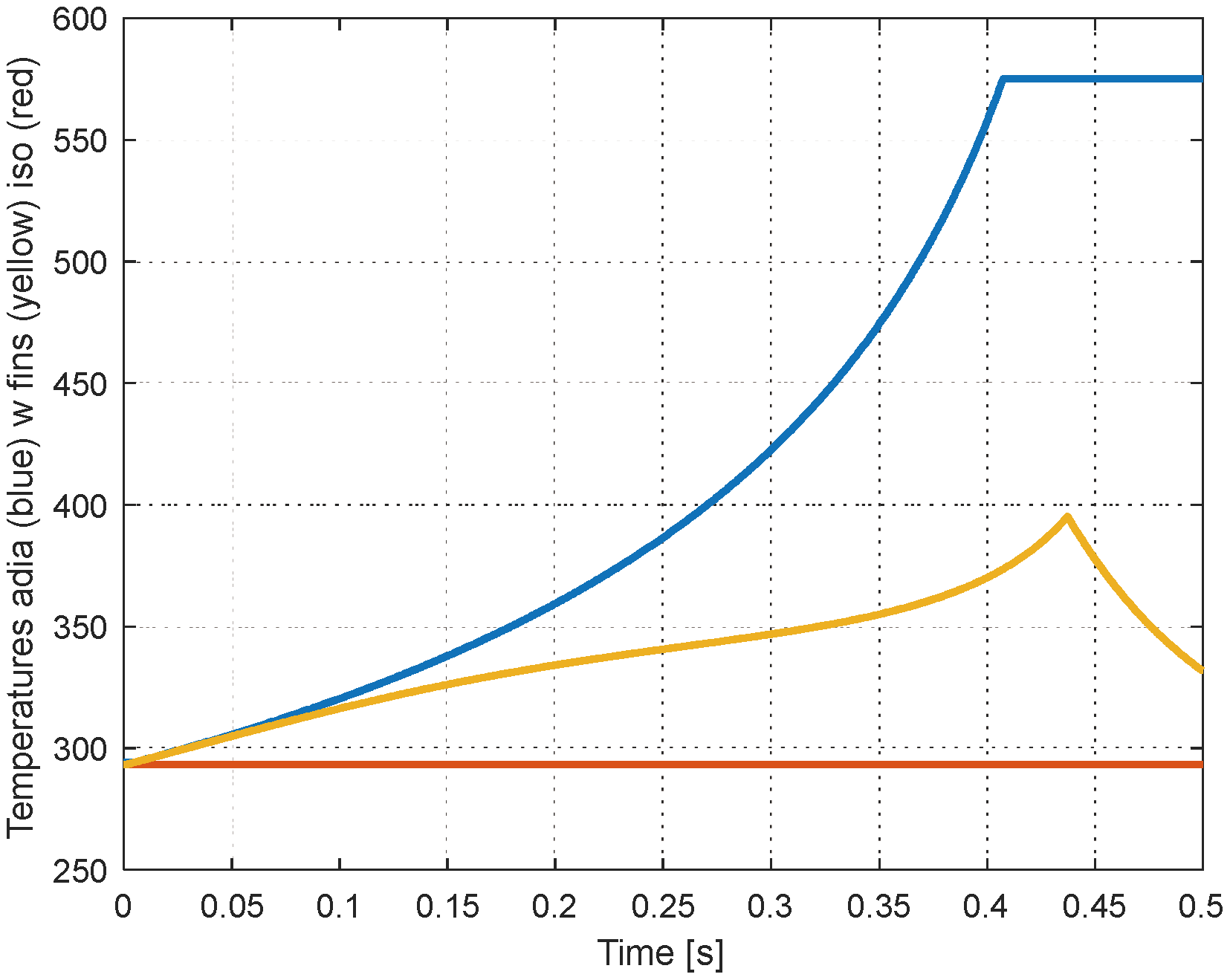
Figure 15.
Temperatures with reduced speed: a) 0.09 m/s, b) 0.045 m/s.
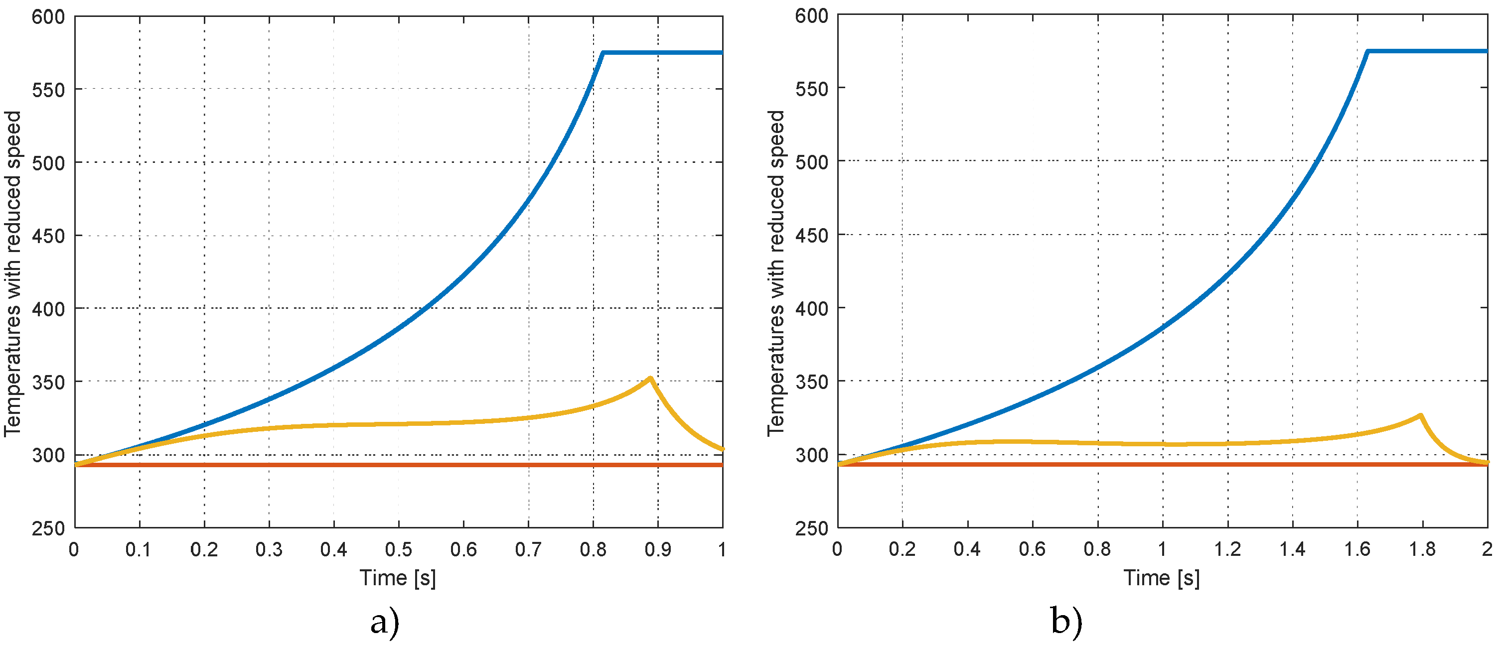
Figure 16.
Mechanical work for the compression adia (blue) finned (yellow) iso (red).
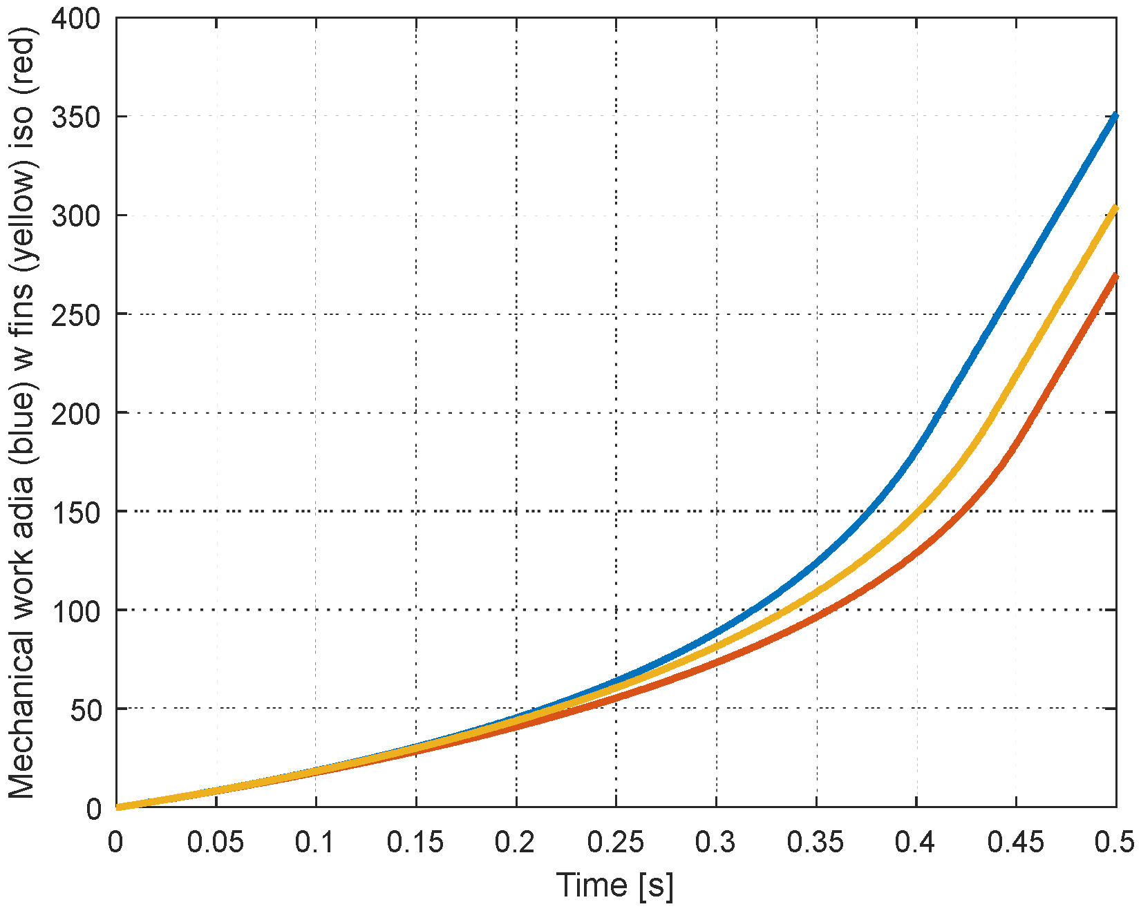
Figure 17.
Energy transferred from the piston to the gas in the cylinder.
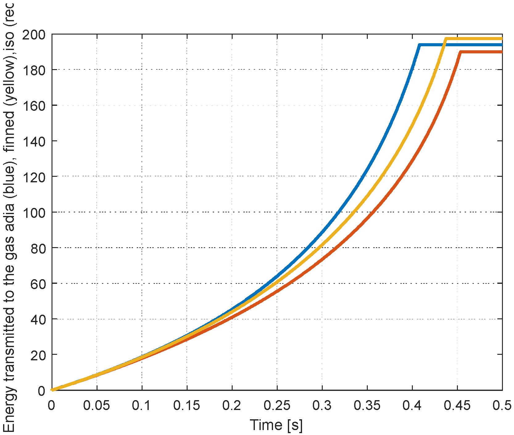
Figure 18.
Mechanical work with reduced speed: a) 0.09 m/s, b) 0.045 m/s.
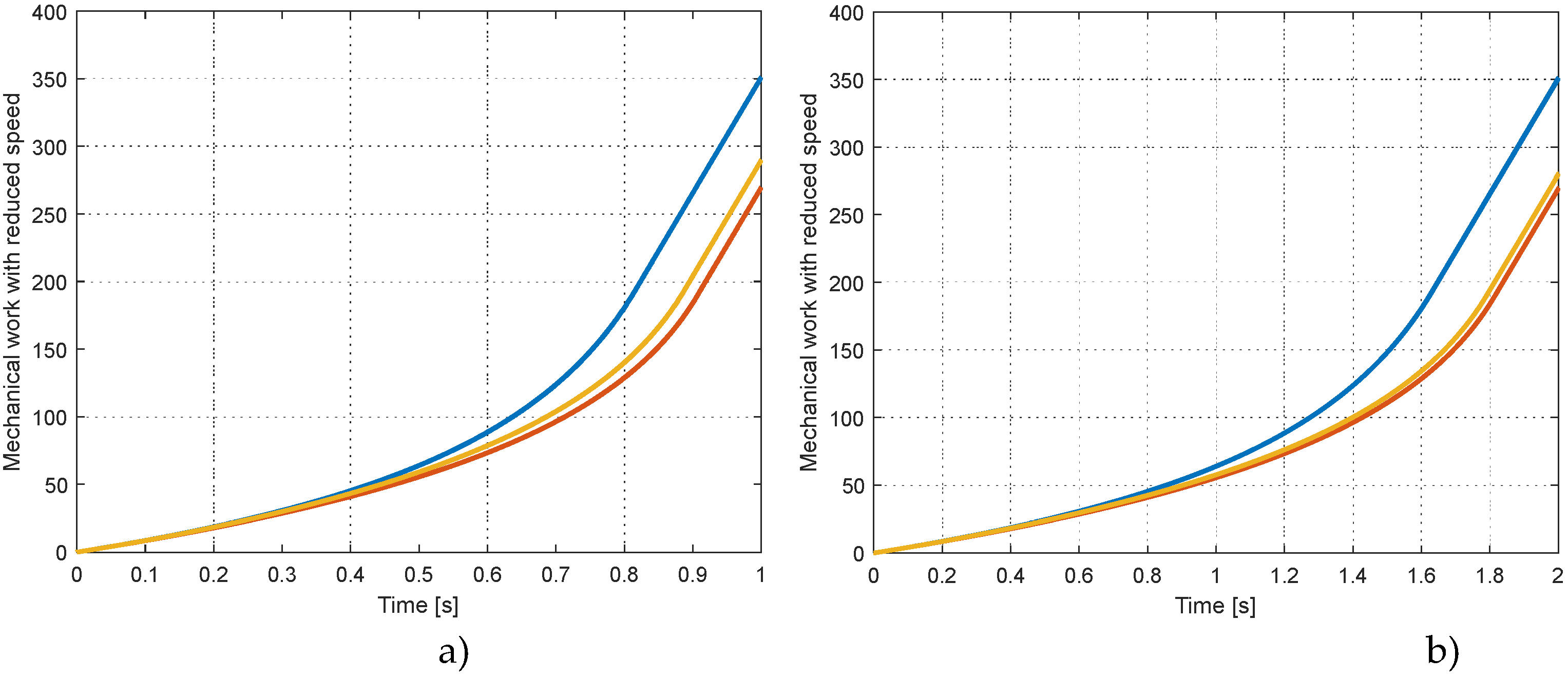
Figure 19.
Compressor with two cylinders (180° phase-shift) and cooling of the fins.
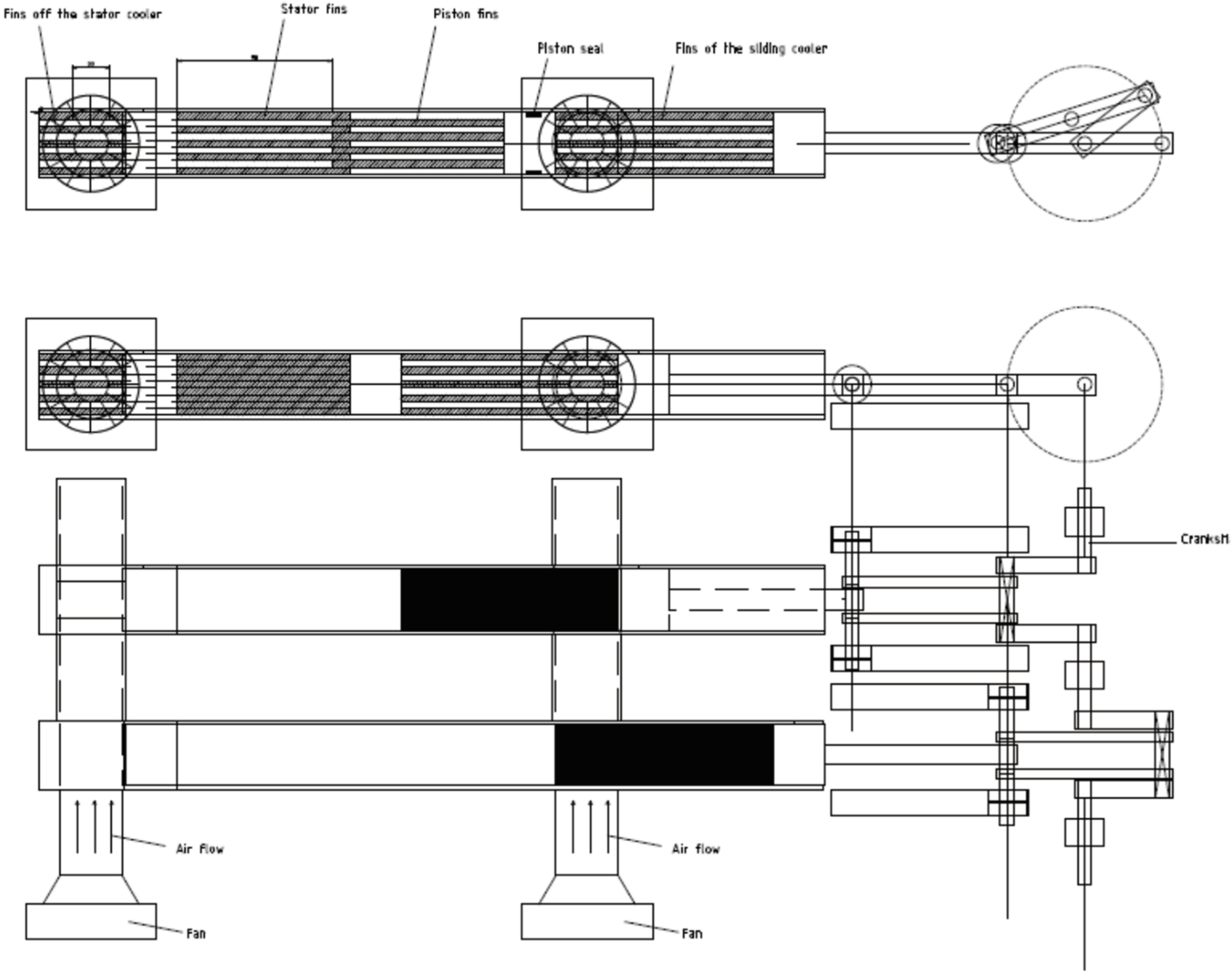

Table 1.
Dimensions of the system.
| Cyl internal diameter | Fin thickness | Active length of the cylinder | Stroke |
| D=27.5 mm | h=2.5 mm | L=100mm | 90mm |
Disclaimer/Publisher’s Note: The statements, opinions and data contained in all publications are solely those of the individual author(s) and contributor(s) and not of MDPI and/or the editor(s). MDPI and/or the editor(s) disclaim responsibility for any injury to people or property resulting from any ideas, methods, instructions or products referred to in the content. |
© 2024 by the authors. Licensee MDPI, Basel, Switzerland. This article is an open access article distributed under the terms and conditions of the Creative Commons Attribution (CC BY) license (http://creativecommons.org/licenses/by/4.0/).
Copyright: This open access article is published under a Creative Commons CC BY 4.0 license, which permit the free download, distribution, and reuse, provided that the author and preprint are cited in any reuse.


