Submitted:
20 February 2024
Posted:
21 February 2024
You are already at the latest version
Abstract
Using the senses is essential to interact with objects in real-world environments. However, not all the senses are available when interacting with virtual objects in virtual environments. This paper presents a diamond methodology to fuse two technologies to represent the senses of sight and touch when interacting with a virtual object. The sense of sight is represented through augmented reality, and the sense of touch is represented through kinesthetic haptics. The diamond methodology is centered on the user experience and comprises five general stages: Experience design, Sensory representation, Development, Display, and Fusion. The first stage comes from the expected, proposed, or needed user experience. Then, each technology takes its homologous activities from the second to the fourth stage, diverging from each other along their development. Finally, the technologies converge to the fifth and final stage for fusion in the user experience. The diamond methodology was tested by generating a user's dual sensation when interacting with the elasticity of a tension virtual spring. The user can simultaneously perceive the visual and tactile change of the virtual spring during the interaction, representing the object's deformation. The experimental results demonstrated that an interactive experience can be felt and seen in augmented reality following the diamond methodology.
Keywords:
augmented reality
; haptics
; immersive technologies
; technologies fusion
1. Introduction
The physiological mechanisms people use to interact with an environment, whether real or virtual, are known as senses. Through touch, sight, smell, hearing, and taste, people perceive the world and take action based on their feedback [1]. It is not easy to imagine exploring a new environment without the information acquired by the senses. However, the scientific community has been working on representing the world artificially and the interaction people have with it to explore and experience a great variety of environments at hand. Therefore, when an individual needs to interact with a virtual environment, the use of the senses is slightly different.
Nowadays, there are interactive and artificial environments that allow people to perform activities like learning anatomy [2], simulating dental surgeries [3], training for assembly operations [4], and experiencing object roughness modulation [5]. Historically, sight and hearing have experienced the most significant advances regarding reliable virtual environments due to the belief that vision and audition convey the most information about an environment [6]. Nevertheless, to have an experience close to reality, people should feel immersed in any environment, and multiple kinds of feedback should be integrated.
Sight and touch are a person’s primary information sources when interacting within an environment. Humans perceive 80% of the information through the eyes [7]. Therefore, if people lose hearing, taste, or smell, they could still prevent damage by sight. Imagining life without a sense of touch is rare and hard in this scenario. Touch sensation is complex, allowing us to perceive our limbs’ position (proprioception) and movements (kinesthesia). The sense of touch is present in all senses due to the nerve endings in each organ related to them.
During the interaction with virtual objects, it is expected to react by trying to touch what is seen because people have the intrinsic desire to touch. Hence, offering the sense of touch in virtual environments could be helpful for the development of interactive experiences [8]. Furthermore, touching (haptic feedback) virtual information can increase the experience’s realism and user immersion [9].
The artificial representation of the sense of touch has become a challenge due to the multidisciplinary approach needed. The field of haptics explores areas like robotics, experimental psychology, biology, computer science, and systems and control [10]. Just like auditory feedback can be described in terms of fidelity, haptic feedback can be described in terms of transparency. For example, in a teleoperated robotic system, transparency can be defined as how the telepresence and the remote environment can be created with haptic feedback [11].
People benefit from haptic and visual feedback when performing different activities to make decisions, explore, or learn from an experience. The interaction might be compromised if the information does not match the user expectancy, and the task might not have the expected benefits, potentially causing confusion or frustration. Therefore, when visual and haptic feedback is introduced to a user in a virtual experience, a design methodology is needed to ensure the information corresponds to the real experience the user expects.
Previously, interesting research had tracked haptic gestures or haptic interactions to manipulate virtual objects in AR [12,13]. Others had worked with visual feedback through Virtual Reality (VR) or Augmented Reality (AR), and haptic feedback through haptic devices have been fused [14,15,16,17,18]. However, to the best of our knowledge, the results reported the applied fusion, but none of the works have reported explicitly a methodology for fusing both technologies in general terms. Moreover, fusing technologies with different specifications and characteristics is challenging. This paper presents a methodology for fusing AR and kinesthetic haptic technologies.
This paper aims to propose the fusion of visual and haptic feedback. Therefore, we present a user-experienced-centered method for fusing the technologies of AR and kinesthetic haptics. The methodology aims to generate a haptic sensation in a user when interacting with a virtual object’s physical property in an AR environment through a kinesthetic interface. The main contributions of the work are summarized below:
- We propose a diamond form methodology with five stages to fuse AR and kinesthetic haptics technologies.
- A homologous step in each stage of the methodology for developing visual and haptic sensation, starting and ending on the user experience.
- We present a case study to see and feel the interaction with a tension virtual spring.
- We demonstrate that an interaction with a virtual object could be seen and felt simultaneously, yet uncoupled.
The rest of the paper is organized as follows. Section 2 shows the background regarding AR and haptics. The diamond methodology is presented in Section 3. In Section 4, the experimentation is shown, applying the methodology to an interaction with a virtual spring experience. The experiments and results are discussed in Section 5. Finally, the conclusions are presented in Section 6.
2. Background
In this section, the background of Augmented Reality and Haptics is presented. Each technology’s main concepts and classifications are discussed to delimit the considerations taken for the methodology proposed.
2.1. Augmented Reality
AR is becoming an important tool in many science fields [19]. AR aims to supplement reality rather than completely replace it. In an AR environment, virtual objects are superimposed into the real world, allowing the user to simultaneously see the real world and computer-generated information. Ideally, the user would feel like the real and virtual objects coexist in the same space because it is registered in 3D (Three Dimensions) [20]. Virtual objects can be superimposed into real life through optical or video techniques.
Optical techniques include see-through Head-Mounted Displays (HMD) with placed optical combiners or fixed monitors with combiners. In the see-through HMD, the combiners are partially reflective and placed in front of the user’s eyes. Virtual information bounces off combiners in the fixed monitors, augmenting a monitor’s information. On the other hand, video techniques comprehend either video see-through HMDs with a closed view in front of the user’s eyes or a monitor/screen placed in front of the user. Video see-through devices display real-world video captured by one or two head-mounted video cameras. Then, it combines the video with graphic information. The monitor/screen view displays the video of a real scene captured by one or two static or mobile video cameras with combined graphic information. The methodology proposed in this paper could be applied to either optical or video AR techniques. However, the experimental application of the methodology was tested using a monitor/screen to display the video of the real scene using a static video camera with combined graphic information of the virtual object. Since AR must merge real and virtual, it should allow user interaction in real-time. In AR environments, graphic information is registered in 3D over the real world through tracking [21].
The work of Stankovic [22] described two main groups of tracking technologies. The first is contact-based tracking, which includes mechanical tracker systems with kinematic structures and mechanically attached sensors. The second is contactless tracking, like electromagnetic, acoustic, and optical tracking. Other tracking technologies, like inertial tracking, are often combined with other methods and technologies due to their high drift problem. The methodology proposed in this paper is applied to an optical tracking technology called marker-based tracking. Marker-based tracking uses a fiducial marker to overlay the graphic information into the real world. However, the methodology comprises other tracking technologies as long as they allow to set the object in a common reference frame.
2.2. Haptics
The word haptic comes from the Greek haptesthai that is interpreted as to touch or related to the sense of touch. The sense of touch is essential for people to explore an environment. Lederman and Klatzky [23] described exploratory procedures made by the hands to recognize an object: lateral motion, pressure, static contact, unsupported holding, enclosure, contour, part motion test, and function testing following to explore texture, hardness, temperature, weight, global shape/volume, global shape / exact shape, moving parts, and specific functions. Humans explore through the sense of touch, mainly with their hands but also through the skin. Haptic interfaces are developed to represent the sense of touch artificially.
Haptic interfaces are feedback devices that generate sensation in the skin or muscles, including a sense of touch, weight, and rigidity [24]. Commonly, Haptic interfaces are classified as cutaneous and kinesthetic, whether the stimulus is to the skin or muscles, respectively. Also, haptic interfaces can be related to active and passive exploration modes for each classification [25]. In this paper, the methodology proposed considers a kinesthetic active haptic interaction since the user applies motion and force consciously to a device, obtaining reaction motion and force as haptic feedback.
When someone touches an object in the real world, the person perceives contact forces depending on the object’s physical properties and the contact location, orientation, and velocity [26]. A haptic rendering is performed to estimate the interaction-related forces for a haptic interface to display a realistic experience of virtual object interaction. The term “haptic rendering" was first presented by Salisbury [27] as “the process of computing and generating forces in response to user interactions with virtual objects". The haptic rendering comprises various methods and techniques depending on the user’s interaction with the virtual object. For example, certain interactions might require the haptic rendering of a surface, texture, form, or rigidity. Also, each interaction can be haptically rendered in different approaches like point-to-point based, point-to-plane based, plane-to-plane based, or point-to-surface based contact.
3. Diamond methodology for Augmented Reality and Kinesthetic Haptics fusion in user experiences
Due to the importance of visual and kinesthetic feedback in virtual experiences, we propose a user-experience-centered method for fusing the immersive technologies of AR and haptics. The diamond form represents the relation between each other’s development counterparts to generate visual and haptic feedback simultaneously, although they could work uncoupled. Each technology takes its path beginning from a common reference frame. Then, the technologies are developed separately to represent sight and touch. Finally, the fusion occurs inside the user, during the experience implemented in the last stage, through the common reference frame designed in the first stage.
The proposed diamond methodology comprises five stages, including i) Experience design, ii) Sensory representation, iii) Development, iv) Display, and v) Fusion, in which the development of each technology takes place. Figure 1 depicts the proposal, and each stage is explained in the following subsections.
3.1. Stage 1, experience design
The proposal describes the interactive experience that should be displayed to the user. Next, the object to interact with and the physical property that will be displayed must be selected. The physical property of the object selected must be part of the dynamic behavior that the user interacts with. Therefore, this stage includes the following:
- Virtual object and physical property selection.
- Identification of graphical and mathematical models to describe the dynamic behavior of the virtual object.
- Reference frame design for user experience.
The methodology starts with a need for a user experience. The designers must identify the virtual object they want to represent visually and its physical to be represented haptically. The visual information will be displayed based on the 3D object’s characteristics. The haptic information will be based on a physical property for the user to feel.
The graphical model is planned to change dynamically during the user experience. The designers must define what characteristics will change and how. For example, if the object to represent is a sponge, the user could interact with it through different exploratory procedures that would change its form. The designers should decide how the user would experience the interaction and how the object would visually change. The haptic feeling of the user must be described as a physical property. The physical property should be force-related due to the nature of the kinesthetic haptic. Like the graphical model, the feeling of interacting with a virtual object is planned to change dynamically during the user experience. The user can choose from physical properties like the ones shown in Table 1.
As seen from Table 1, most force-related physical properties are mechanical due to their close relation with materials and forces. Once the virtual object and its physical properties are selected, the designers must identify the graphical and mathematical models selection of the graphical and haptic model to represent them. For the graphical model, it is important to determine the size and shape of the object so as the tools to use, like Computer-Aided Design (CAD) software to design the graphical model and a software framework to develop a graphical rendering of the AR scenes. As the counterpart in haptics, the designers must work on identifying the mathematical model that describes the selected physical property. That model will be the one to describe the interaction force that the user will be feeling during the final user experience.
Finally, the designers must sketch the reference frame where the user will interact with the virtual object. The reference frame must be designed and centered on the user experience. When users have no idea of what to expect from the experience, they may lose interest, motivation, and other benefits that could come with it. Some authors take time before tests to teach the user how to manipulate the devices and how to perform an interaction to ensure the user experience is carried on successfully. In this stage, the main reference position is defined considering the haptic interface mechanism and the planned dynamic visual and haptic changes. All the experience variables must be considered and depicted graphically and conceptually. The experience variables are all positions that the designers plan to use as a reference for the user´s experience.
Figure 2 shows a reference frame for an interactive user experience where all the experience variables are defined graphically. The experience variables are defined conceptually in Table 2. The example is based on a lever mechanism, and the position is an angle. For practical purposes, the angular position will be named position and referenced as x.
The design involves the planning of the experiment and the experience of interacting with the physical property of the virtual object in an AR environment. Users must be aware of every step of the interactive experience to interact more confidently. Users who try new technologies usually do it with fear, mistrust, self-consciousness, or unsteadiness. This feeling is understandable due to users’ uncertainties about how to use the latest technology. A detailed explanation of the experiment interaction might attenuate this feeling.
The following set of questions can be a guide in which the answers aid the experience interaction plan.
- Where should the user be positioned?
- What hand should the user use? Is it relevant to the experience?
- What should and should not the user grab?
- How should the user interact with the virtual object?
- Are there any constraints on how the user should perform the experiment?
- What will the user see?
- What visual information will be displayed?
- Where will the visual information be displayed?
- What will the user feel?
- What haptic information will be displayed?
- Where will the haptic information be displayed?
The user experience strongly depends on the purpose of the experiment. Other questions could be made to focus on the user experience. Once those questions are answered, a detailed step-by-step instruction list should be made. The instructions are recommended to have graphical information to ease the understanding of the user.
3.2. Stage 2, Sensory representation
During the second stage, the development of each technology takes its own homologous path. AR technology carries on the sensory representation of sight by constructing the graphic model of the virtual object based on the characteristics and positions determined on the reference frame stage. The kinesthetic haptics technology represents the sense of touch as a force. Therefore, the mathematical model of the physical property selected in the first stage is programmed in this stage.
3.2.1. Graphical model
The graphical model will be superposed in an AR scene to represent the virtual object with physical properties. The model can be designed in CAD software to import it into the AR scene later and change it dynamically. The user will see this graphical model as a virtual object.
At this point, the designers must know where will the virtual object be positioned, so it is important that in this stage, they define how the graphical model will be superposed and tracked in the AR scene. There are many technologies to position and track the visual information in an AR scene.
The easiest way to produce and place landmarks in the environment is with images designed for this purpose, called fiducial markers [28]. It is recommended to start by superimposing, positioning, and tracking the virtual object through fiducial markers.
Fiducial markers have known dimensions and features, allowing a method of pattern recognition to identify them in the world’s coordinate system. Markers should be designed with features like corners, shapes, and a unique pattern. QR codes have been widely implemented for this purpose. Another consideration for the design of the markers is asymmetry. When the marker translates and rotates, an asymmetrical design lets one keep track of the marker’s direction [28]. Finally, the marker image must be associated with a 3D model. For example, if the marker is used for displaying a virtual cat, the marker can be associated with the cat by writing the word cat in a corner or drawing an icon of a cat at the center. If the designers decide to use markers to register the virtual object in the AR environment, they should follow the previous advice to generate the corresponding markers of the user experience they are developing.
3.2.2. Mathematical model
The mathematical model, usually called haptic rendering, estimates the haptic information to be felt by the user during the experience. The haptic information considered in this methodology is kinesthetic, with variables like position, velocity, acceleration, force, torque, etc. The following description focuses on force as the kinesthetic haptic information.
The mathematical model describes the behavior of an object due to a specific physical property. In the model, the designers may set the limit of the force interaction based on the mechanism to be used as a haptic display if they are known.
Physical properties have an impact on the behavior of an object when it is manipulated. The behavior is the response to a force interaction that can be described as a function or mathematical model. The function should be determined in terms of the physical property and the variables of position x, velocity , or acceleration as shown in equation (1). The result of the function will be the force reference of the control scheme. Most models relate the physical property to its behavior when the user applies a force.
Determining the maximum magnitude of the interaction forces that the haptic interface can display is imperative. The haptic interface is a mechanism with electrical and mechanical constraints. Therefore, the interaction forces displayed by the device depend on those constraints. The motor features obtained from the motor characterization and the power source can be used to determine the maximum magnitude of the torque exerted by the motor. The torque that the motor exerts determines the interaction forces limit as shown in equation (2).
where is the maximum torque the motor can exert, is the maximum current in amperes that the power source can deliver, and is the experimental torque constant of the DC motor. It is important to ensure the motor driver and the motor support the same or more current than the power source so the driver and motor do not overheat. The lower current support should be considered for this estimation. A percentage of can be set as the real limit for safety purposes. This way, the power source will not break down, or the circuit breaker will trip when the is reached.
Once the maximum torque reference that the motor can exert is calculated, the parametric limits of the physical property selected will be estimated. The limits are estimated by the and the function that defined the torque reference in terms of the physical property and the variables of position x, velocity , and acceleration . The limits are defined to establish the feasible magnitudes of the chosen physical property that can be represented.
3.3. Stage 3, Development
In this stage, the development of each technology is carried out individually. This is the furthest point between technologies; they started from a common reference frame and diverged to this stage. The graphic rendering carries on the programming and configuration of the AR environment with an outcome of an AR scene that the user will see displayed on a screen. The control scheme carries on the programming of force control in which the outcome is the signal, allowing the haptic interface to display the force corresponding to the user experience when interacting with the virtual object.
3.3.1. Graphic rendering
The graphic rendering is conducted on a graphics engine software. Most graphic engines support different libraries and tools for tracking. The libraries allow monitoring of the objects’ position simultaneously with graphical transformation. First, the virtual object is planned to change its transformation regarding the user´s interaction during the experience. Second, depending on the reference frame, the 3D virtual model should suffer a change in position, rotation, or scale. These two considerations should be taken into account to program the visually dynamic change in the virtual object during the experience.
The graphic engine does not need an additional physics library or tool since the kinesthetic haptic generates the haptic information. In this case, the graphic engine processes the graphics, and no other computational load is added. In AR environments, the computer vision problem of identifying and reconstructing the environment can be eased by adding landmarks at key points. Therefore, in the graphical model stage, we suggest using fiducial markers. The fiducial markers have two main purposes. The first is to place the virtual object in the real world, achieved in the Sensory representation stage. The second is to keep track of the haptic interface manipulation. The second purpose allows the identification of a change in the current position so that the virtual object can be transformed in the graphic rendering stage, programmed in this stage.
3.3.2. Control scheme
The control scheme allows getting a desired control signal given an input value by, for example, compensating, adjusting, estimating, and/or filtering it. We recommend that the control outcome is saturated by software to the maximum magnitude of the interaction forces that the haptic interface can display. The was estimated at the previous stage.
The control scheme should generate a control signal for the haptic device to display the force corresponding to the user interaction during the experience. We recommend considering applying a sensorless force control due to the high cost, poor maneuverability, and fragility of force sensors. We also recommend a force control with a force reference input. The force reference would be estimated by the mathematical model of the haptic rendering and then sent as input of the control scheme. The control scheme can be taken from traditional or modern control theories.
3.4. Stage 4, Display device
In the fourth stage, the methodology starts the convergence of the two technologies, yet they are still uncoupled. This stage tests the display of visual and haptic information separately before the fusion stage. The corresponding outcomes of the development stage are now displayed through the corresponding device. The AR scene and the control signal are sent to a display device and a kinesthetic haptic device, respectively.
3.4.1. Display device
The display of the virtual object is based on the reference frame designed in the first stage. The purpose is to display the visual information to the user in an AR environment. The AR scene can run on a Personal Computer (PC), tablet, or mobile device. In this stage, the positions of the visual feedback and the virtual object’s graphical model are set over the real world through a display device like a laptop, monitor, mobile device, tablet screen, etc. If the haptic interface is considered a desktop device, it is recommended that the display device also be a desktop application with a computer monitor or a laptop screen. However, other displays like HMD or mobile devices can also be considered. The screen must be positioned in such a way that the user can easily reach the haptic device and see the AR environment at the same time.
3.4.2. Kinesthetic haptic interface
A haptic interface is a device that makes a user feel like touching something. This methodology focuses on kinesthetic haptic feedback, meaning that the haptic information displayed is force-related. The device is an actuated mechanism. The designers must consider the mechanical constraints and, if necessary, add mechanical limits to avoid injury or harm to the user during the experiment. The type of device and the number of degrees of freedom can be chosen, although it is recommended to consider them for the reference frame design. The interface can be designed or bought as long as the user experience designers know how to introduce the control signal so that the device acts as desired.
3.5. Stage 5, Fusion
The lack of transparency when generating the feeling of touch for interactive activities leads to a far-from-reality experience. In a virtual environment, verifying the realism and experience of haptic interaction is necessary. When the haptic interaction is kinesthetic, the verification should be in terms of kinesthetic variables like force and position. The diamond methodology to fuse AR and kinesthetic haptics proposed in this paper is centered on the user experience. Still, the approach towards the development of each technology is homologous and uncoupled until this final stage. By uncoupled, it is meant that both technologies could work and be tested separately from each other. However, there should be initially planned as a single fusion experience where the user can see and feel the interaction with a virtual object. The AR does not need an additional physics engine for the force/torque estimation since the kinesthetic haptics stages are in charge. Likewise, the haptic interface can display forces related to the user experience planned, even if the AR scene is not yet loaded. The importance of the AR module is to close the visual loop with the user, allowing to see what is felt.
Both technologies are fused in this stage and converge to a single user experience. Although their development diverged during the second and third stages, the reference frame designed in the first stage guides them with homologous activities and a common objective. Know that fusion occurs when the markers are positioned over the kinesthetic haptic interface, coinciding with each technology’s reference. The visual and haptic information should now be displayed at the same time. There might be a need for a camera setup to allow users to interact freely with the virtual object. The camera can be fixed over the haptic interface if the haptic interface is a desktop device. If the haptic interface is wearable, the camera setup can be either held by the user with one hand and the wearable on the other, or it can still be fixed and determine a work area.
4. Methodology Experiment: The Virtual Spring
This section presents an example of implementing the proposed diamond methodology to see and feel a tension virtual spring. Springs are typical objects employed in haptics experimentation due to their flexibility to represent cloths, hair, walls, skin, organs, and sponges by changing the spring coefficient or arranging different configurations with or without dampers and other mechanisms [29].
4.1. Stage 1
The application of the diamond started with the selection of the virtual object and the physical property to represent the user experience. The virtual object selection came from the fact that an interaction with a spring model can represent other experiences related to active exploratory procedures, like applying pressure to explore the hardness of any object. For the tension spring case, the physical property selected was elasticity. Later, the graphical and mathematical models were identified as follows:
- Graphical model: tension spring with hooks, a free length of 4cm, a body length of 2cm, and an outside diameter of 1cm. Solid Works®was selected as CAD design software.
- Mathematical model of elasticity: Hooke´s Law.
The reference frame was proposed after selecting and identifying the visual and haptic models. The proposition was based on the positioning of the virtual object for user interaction. In Figure 3, the tension spring is represented in the reference frame proposed. The interactive object that the user will feel and see is also collocated to visualize the expected result in a diagram. The form of the haptic interface can be considered if the mechanism is known from the beginning.
The reference points of the experiment were identified in a picture of the experimental setup, as shown in Figure 4, where the markers and virtual spring were overlapped to plan the tracking. One marker was planned to be fixed, and the other to move with the haptic lever manipulation. Then, the virtual object would be overlaid on the marker placed in the Position Reference of the fixed marker.
The following list details the user experience instruction plan to interact with a virtual spring.
- The user sits in front of a desk where the haptic interface and a computer screen are positioned.
- The user employs the right hand to move the haptic interface.
- The user grabs the haptic interface from the end effector. The user should not grab the haptic interface from the base or joints.
- Once the user grabs the end effector of the haptic interface, he/she can move it in two directions (back and forward), parting from a specific starting point.
- Make sure not to make rotational movements. Make sure to grab the end effector of the haptic interface during every movement; do not release it when the haptic information is displayed unless indicated.
- The virtual spring will be displayed on the screen right between the two reference points from real life.
- The user should move the end effector to the starting point to start again.
- The user will feel like stretching and releasing a virtual spring when moving between two reference points. The user will experience a linear force profile of resistance to the stretching.
- The force feedback will be generated from the device’s motor.
4.2. Stage 2
Stage 2 is about seeing and feeling a virtual spring. In stage 1, graphical and mathematical models were identified as what the user will see and what the user will feel during the experience. In this stage, those models are designed and programmed, respectively.
4.2.1. Graphical model
In this section, the graphical model of the proposal is designed. The reference points determined in the previous stage are required to position the markers. The user manipulation of the haptic interface position was planned to be tracked with the fiducial markers. Then, the virtual 3D object is placed over the real environment. In the following stage, the virtual object will be programmed to transform as the user manipulates the haptic interface position. Finally, the visual information is displayed to the user through a display.
The graphical model designed was a tension spring with two hooks. The tension virtual spring was designed in CAD software called Solid Works ®. Later, it was imported into the graphic engine Unity 3D ®. Finally, a test marker was added to the main scene, and the spring CAD was attached, as shown in Figure 5.
4.2.2. Mathematical model
The mathematical model represents the haptic rendering that estimates the haptic information that should be displayed to the user on the haptic interface. In this case, the diamond methodology considers kinesthetic haptic information, such as position, velocity, acceleration, force, torque, etc. The mathematical model used for the virtual spring is Hooke’s Law. With Hooke’s Law, the force reference can be rendered according to the user’s interaction with a virtual spring. A spring constant was chosen to represent a real tension spring. The interaction force was estimated with Hooke’s Law depicted in equation (3).
where is the interaction force when pushing/pulling a spring, is a known spring constant, and x is the spring extension when is applied at one end of the spring. The expected values of the maximum torque and the maximum displacement of the experiment must be considered for estimating the parametric limits of the spring constant. Since the torque reference will be the control variable for the control scheme, it was calculated with the moment arm of the mechanism (length of the lever), and the force reference as shown in equation (4).
where r is the moment arm and is the angle between the moment arm and the vector of the interaction force at the application point, as shown in Figure 6. The force direction is represented by an arrow that starts in the lever and goes to the spring, indicating the tension exerted by the spring when the user extends it. For practical purposes, the angle will be 90 degrees living the torque reference calculation as in equation (5)
The force reference is the force interaction that will be displayed to the user. The torque reference is the torque that the motor will exert.
4.3. Stage 3
In stage 3, the development of both visual and tactile sensory representations is carried on. From the first stage, the methodology diverged to the third. The output of the stage will start converging to the final stage, where the fusion will occur. The AR and Haptics technologies are the furthest away at the development stage, so they can be tested individually before the fusion. This section describes how the graphic rendering and the control scheme were developed.
4.3.1. Graphic rendering
The graphic rendering was developed in Unity 3D® [30]. Unity 3D® is a powerful game engine that allows graphics rendering, transformation models, lighting manipulation, and collision detection. Unity 3D® was chosen due to its flexibility to manage a wide range of platforms, extensive documentation, and many extensions and Software Development Kits (SDKs) developed for it.
A new project was created, and an AR camera object was added. Then, the markers database was imported into the Vuforia extension. Finally, both markers were positioned on the origin of the AR camera’s coordinate frame.
The virtual spring transformation was modified to appear extended when separating the two markers. The spring extension l is estimated considering the distance between the markers d following the linear model:
where the parameters m and b modified the spring’s extension behavior and were obtained experimentally to appear realistic.
4.3.2. Control scheme
The control scheme and calibration method for the control gains presented in [31] was implemented within the development stage of the kinesthetic haptic technology; a detailed step-by-step was described in that work. The control scheme, represented in Figure 7, describes the torque control scheme based on a Disturbance Observer (DOB). The control scheme receives a torque reference as a control input from the mathematical model. As part of the sensory representation stage, the velocity of the DC motor is estimated to be later characterized, and the parameters are used to set the force interaction limits. The control scheme sends the control signal to the haptic interface for the mechanism to display the haptic information corresponding to the user interaction.
The control saturates on the maximum torque expected when the torque reference exceeds that value. The control also saturates in zero if the position reference is surpassed. When the user interacts with the tension spring, the reference point is located right on the side of the tension spring in a stationary state. Therefore, when the user moves the lever away from the reference point, the force magnitude increases opposite to the user’s movement, pulling the hand of the user to the reference point. For this experiment, the spring constant was calculated for displaying a maximum torque of when the maximum tension of the spring is reached, resulting in a .
The torque applied by the motor during the experiment is in the opposite direction to the hand motion, rendering a dynamic force related to the user’s interaction. The torque reference changes dynamically with the user’s motion control and is proportional to the estimated force, , as in equation (6).
where is the torque reference (control input) and r is the moment arm of the Haptic Lever, .
Figure 8 shows the experimental and simulation results of the interaction with a tension virtual spring. The tension virtual spring is stationary, as shown in Figure 3. The spring edge is in the 0 radians reference point. The experiment starts by pulling the spring from 0 to approximately 3 radians (Figure 8a). The movement was made while maintaining a constant velocity to compare the behavior with the simulation in Figure 8b. As can be observed in Figure 8c, the maximum torque was reached at 1 radian, so the torque rendering is saturated at as a safety condition. A slight vibration in the response was observed in the zoom area, but the amplitude was not perceptible. The linear behavior of the torque rendering is similar to the simulation shown in Figure 8d.
4.4. Stage 4
In stage 4, the methodology starts converging to the fusion by displaying the visual and haptic information that, although it is yet uncoupled, they start working under the same reference frame.
4.4.1. Display device
The visual information was displayed on a Laptop screen with a 1920x1080 resolution at 60 Frames Per Second (FPS). A database with all the needed markers for the display test must be added to the tracking library to identify them correctly. Regarding two reference points, the two tracked positions are computed and entered into a graphic engine. Figure 9 shows the visual information generated.
The extension was determined as the difference between a reference and the current position of the haptic interface, as described in the graphic rendering. In this stage, there can be adjustments to the estimated transformation.
4.4.2. Kinesthetic haptic device
The kinesthetic haptic device selected to display the haptic information was The Haptic Lever designed in [31] in Figure 10; the haptic interface is represented, so as the signals related to the other stages like the control signal and the reference frame. The main elements of The Haptic Lever are the DC motor, which generates the haptic information according to the control signal that comes from the control scheme, and the lever, which displays the haptic information directly to the user.
The reference frame is the information corresponding to the experiment or sensation that wants to be displayed, designed in the first stage. The design must consider the mechanism of the haptic interface. A one Degree-of-Freedom (DoF) kinesthetic haptic interface is considered for the study case of the diamond methodology. However, other devices with more DoF could be used. The haptic information represents the sensation the user feels. A two-way arrow was used to represent the bilateral nature of the sense of touch. The Haptic interface displays haptic information corresponding to the user’s interaction with the mechanism.
4.5. Stage 5
A camera was rigidly placed on an aluminum base. As shown in Figure 11, the camera setup considers the camera facing downward to the experimental area in such a way that the workspace of the haptic interface can be captured. Next, the markers are placed on the reference points from the first stage. The user manipulates the haptic interface position, and the motion is captured by one marker tracking. Then, another marker is placed on a different reference point. An interaction might require more than two markers.
Altogether, the markers allow closing the interaction loop visually while the user feels like stretching the virtual spring. Figure 12 shows in two frames how the user could see and feel as if pulling a tension spring. The spring constant taken as a reference for the interactive experiment was =2.5N/m.
The fusion is the last stage of the diamond. Figure 13 shows the final experimental set for the fusion of AR and haptics technologies. Since the haptic lever is a desktop device, the AR scene is considered a desktop application. The visual information was displayed on a laptop screen. The visual display was positioned in front of the users and behind the haptic lever so they could reach the haptic device and see the AR environment simultaneously.
The position of the Haptic Lever is sent in two forms: i) as a marker position to the AR scene to make the corresponding changes in the visualization of the virtual object and ii) as a disturbance acquired by an encoder sent to the control scheme to adjust the haptic sensation corresponding to the user interaction with the device.
5. Discussion
In this paper, we presented a diamond methodology with five stages to fuse the technologies of Augmented Reality and kinesthetic Haptics. Each stage was described in terms of activities and steps to make sure both technologies represent visually and haptically an interaction with an object. The first and last stages are user experience-centered. The diamond form represents the divergence from the first stage to the uncoupled development of the two technologies and the convergence from that stage to the fusion of the technologies in one experience. Also, the inner stages of the diamond method have homologous activities and steps to create the dual-user experience. We represented a tension spring to demonstrate that an interactive experience within an AR environment with the feeling of touch can be created using the diamond methodology. Springs are one of the most used mechanisms to validate haptics since it is a basic mechanism that allows the representation of many other objects. The fusion results were described in terms of the visual effect in AR and the touch feeling through the Haptic Lever activation.
Concerning the AR environment, it can be observed that the 3D model generated allows the user to see the spring behavior just as if it were deformed in real life. The results confirmed that AR is useful for representing dynamic phenomena like deformation and motion during user interaction. With the fiducial markers, the virtual object can be inserted and positioned realistically. Also, the distance between markers can be estimated to simulate the expected deformation or motion of the virtual object.
The haptic results demonstrated that the feeling of touch could be generated from the haptic information estimated with the mathematical model in the mathematical model step of the sensory representation stage. Therefore, the haptic information estimated can be displayed in a haptic interface due to the control scheme. The control scheme allows control without the need for a force sensor, which facilitates the start-up of the experience and provides transparency in the haptic feeling. Other control schemes and sensors could also be implemented, but a sensorless control scheme is recommended due to practicality and low cost. The feeling of stretching the virtual spring followed the behavior of a real tension spring. The motor characterization is an important task that should be made carefully to let the observer identify the torque exerted by the haptic interface.
The visual and haptic information coincide by adequately setting the fiducial marker’s position over the Haptic Lever as planned on the reference frame. We recommend fixing the markers to avoid their movement because they mark the reference points of the experiment. If the markers are not fixed to the haptic interface, the reference points and the virtual objects will appear in an unexpected place and the transformation might represent erroneous deformation. We also noticed that a plain background under the markers facilitates the markers’ identification. The diamond methodology does not exclude mobile applications, but we recommend HMDs or desktop applications since the experience requires hand manipulation to feel the interaction.
The methodology proposed is based on homologous classic AR and kinesthetic haptic approaches developed and tested individually but displayed together. From the literature review, we notice that the development of AR experiences that include haptics focuses on specific applications but never proposes a general methodology to fuse those technologies regardless of the study case or specific application. Although we considered a basic interaction, our proposal can be applied to many other case studies of interactive AR-Haptics objects like buttons, wheels, skin, barriers, drills, balls, and fruits.
6. Conclusions
This paper proposed and applied a user experience-centered methodology to fuse the immersive technologies of AR and Haptics to create a visual and tactile experience. The user experience example consisted of manipulating a tension virtual spring. The methodology has five stages in which the designer identifies what to see and feel in the first, how to see and feel from the third to fourth, and how to actually see and feel in the last.
The experimental results demonstrated that following the diamond methodology, an experience to be seen and felt in an AR environment can be created. The experience tested was a tension virtual spring due to its flexibility to represent many other objects. Furthermore, different experiences can be described with constant, linear, and exponential force profiles as long as the parameters of the haptic interface and markers are matched to the corresponding experience.
The proposal has the potential to be implemented in different training and learning scenarios of academic, medical, industrial, and entertaining. The advantages of developing AR-Haptic experiences can be explored in the areas mentioned and their implication for the user. Further work may consist of evaluating the fusion of haptic and AR using different models like Attention, Relevance, Confidence, and Satisfaction (ARCS), Technology Acceptance Model (TAM), Augmented Reality Immersion (ARI), or System Usability Scale (SUS).
Author Contributions
Conceptualization, A.R.R., O.O.V.V., M.N. and F.G.; methodology, A.R.R., O.O.V.V. and M.N.;software, A.R.R.; validation, A.R.R. and F.G.; investigation, A.R.R., O.O.V.V., M.N. and F.G.; writing—original draft preparation, A.R.R., O.O.V.V., M.N. and F.G.; writing—review and editing, A.R.R. and O.O.V.V. All authors have read and agreed to the published version of the manuscript.
Funding
This research was financially supported with funds from CONACYT.
Institutional Review Board Statement
Not applicable.
Data Availability Statement
The data presented in this study are available on request from the corresponding author.
Acknowledgments
The authors would like to thank the Universidad Autónoma de Ciudad Juárez (UACJ) for the support and equipment.
Conflicts of Interest
The authors declare no conflict of interest.
Abbreviations
The following abbreviations are used in this manuscript:
| AR | Augmented Reality |
| HMD | Head Mounted Display |
| ARCS | Attention, Relevance, Confidence, and Satisfaction |
| TAM | Technology Acceptance Model |
| ARI | Augmented Reality Immersion |
| SUS | System Usability Scale |
| CAD | Computer-Aided Design |
| DC | Direct Current |
| DoF | degree-of-freedom |
| DOB | Disturbance Observer |
| PC | Personal Computer |
References
- Hwan, Y.; Park, B.; Uk, J.; Kim, T. Bioinspired Electronics for Artificial Sensory Systems. Advanced Materials 2019, 31, 1–22. [Google Scholar] [CrossRef]
- Skulmowski, A.; Pradel, S.; Kühnert, T.; Brunnett, G.; Daniel, G. Embodied Learning Using a Tangible User Interface: The Effects of Haptic Perception and Selective Pointing on a Spatial Learning Task. Computers & Education 2016, 92-93, 64–75. [Google Scholar] [CrossRef]
- Rhienmora, P.; Gajananan, K.; Haddawy, P.; Dailey, M.; Suebnukarn, S. Augmented Reality Haptics System for Dental Surgical Skills Training. 17th ACM Symposium on Virtual Reality Software and Technology (VRST); , 2010; pp. 97–98.
- Abidi, M.; Ahmad, A.; Darmoul, S.; Al-Ahmari, A. Haptics Assisted Virtual Assembly. IFAC-PapersOnLine 2015, 48, 100–105. [Google Scholar] [CrossRef]
- Culbertson, H.; Kuchenbecker, K. Ungrounded Haptic Augmented Reality System for Displaying Roughness and Friction. IEEE/ASME Transactions on Mechatronics 2017, 22, 1839–1849. [Google Scholar] [CrossRef]
- Saddik, A.E.; Orozco, M.; Eid, M.; Cha, J. Haptics Technologies; Springer-Verlag: Heidelberg, Berlin, 2011; pp. 1–215. [Google Scholar]
- Man, D.; Olchawa, R. Brain Biophysics: Perception, Consciousness, Creativity. Brain Computer Interface (BCI). Biomedical Engineering and Neuroscience; Springer International Publishing: Cham, 2018; pp. 38–44. [Google Scholar]
- Ujitoko, Y.; Ban, Y. Survey of Pseudo-Haptics: Haptic Feedback Design and Application Proposals. IEEE Transactions on Haptics 2021, 14, 699–711. [Google Scholar] [CrossRef] [PubMed]
- Wang, D.; Guo, Y.; Liu, S.; Zhang, Y.; Xu, W.; Xiao, J. Haptic Display for Virtual Reality: Progress and Challenges. Virtual Reality and Intelligent Hardware 2019, 1, 136–162. [Google Scholar] [CrossRef]
- Hayward, V.; Astley, O.; Cruz, M.; Grant, D.; Robles-De-La-Torre, G. Haptic Interfaces and Devices. Sensor Review 2004, 24, 16–29. [Google Scholar] [CrossRef]
- Giri, G.; Maddahi, Y.; Zareinia, K. An Application-Based Review of Haptics Technology. Robotics 2021, 10, 29. [Google Scholar] [CrossRef]
- Nor’a, M.N.A.; Fadzli, F.E.; Ismail, A.W.; Vicubelab, Z.S.O.; Aladin, M.Y.F.; Hanif, W.A.A.W. Fingertips Interaction Method in Handheld Augmented Reality for 3D Manipulation. 2020 IEEE 5th International Conference on Computing Communication and Automation (ICCCA), 2020, pp. 161–166. [CrossRef]
- Oh, J.Y.; Park, J.H.; Park, J.M. Virtual Object Manipulation by Combining Touch and Head Interactions for Mobile Augmented Reality. Applied Sciences 2019, 9, 2933. [Google Scholar] [CrossRef]
- Aleotti, J.; Micconi, G.; Caselli, S.; Benassi, G.; Zambelli, N.; Bettelli, M.; Zappettini, A. Detection of Nuclear Sources by UAV Teleoperation Using a Visuo-Haptic Augmented Reality Interface. Sensors 2017, 17, 2234. [Google Scholar] [CrossRef] [PubMed]
- Lopes, P.; You, S.; Cheng, L.P.; Marwecki, S.; Baudisch, P. Providing Haptics to Walls and Heavy Objects in Virtual Reality by Means of Electrical Muscle Stimulation. Proceedings of the 2017 CHI Conference on Human Factors in Computing Systems; Association for Computing Machinery: New York, NY, USA, 2017; CHI ’17, p. 1471–1482. [CrossRef]
- Ocampo, R.; Tavakoli, M. Improving User Performance in Haptics-Based Rehabilitation Exercises by Colocation of User’s Visual and Motor Axes via a Three-Dimensional Augmented-Reality Display. IEEE Robotics and Automation Letters 2019, 4, 438–444. [Google Scholar] [CrossRef]
- Ocampo, R.; Tavakoli, M. Visual-Haptic Colocation in Robotic Rehabilitation Exercises Using a 2D Augmented-Reality Display. 2019 International Symposium on Medical Robotics (ISMR); , 2019; pp. 1–7. [CrossRef]
- Arbeláez, J.; Viganò, R.; Osorio-Gómez, G. Haptic Augmented Reality (HapticAR) for Assembly Guidance. International Journal on Interactive Design and Manufacturing (IJIDeM) 2019, 13, 673–687. [Google Scholar] [CrossRef]
- Wang, D.; Guo, Y.; Liu, S.; Zhang, Y.; Xu, W.; Xiao, J. Augmented Reality and Artificial Intelligence in Industry: Trends, Tools, and Future Challenges. Expert Systems with Applications 2022, 207, 1–15. [Google Scholar] [CrossRef]
- Azuma, R. A Survey of Augmented Reality. Presence: Teleoperators and Virtual Environments 1997, 6, 355–385. [Google Scholar] [CrossRef]
- Wang, Y.; Zhang, S.; Yang, S.; He, W.; Bai, X. Mechanical Assembly Assistance Using Marker-less Augmented Reality System. Assembly Automation 2018, 38, 77–87. [Google Scholar] [CrossRef]
- Stanković, S. Virtual Reality and Virtual Environments in 10 Lectures, 1 ed.; Morgan & Claypool: London, 2016; pp. 1–177. [Google Scholar]
- Lederman, S.; Klatzky, R. Hand Movements: A Window into Haptic Object Recognition. Cognitive Psychology 1987, 19, 342–368. [Google Scholar] [CrossRef]
- Grunwald, M. Human Haptic Perception: Basics and Applications, 1 ed.; Birkhäuser Basel, 2008; pp. 1–676.
- Rodríguez, J.; Velázquez, R.; Del-Valle-Soto, C.; Gutiérrez, S.; Varona, J.; Enríquez-Zarate, J. Active and Passive Haptic Perception of Shape: Passive Haptics Can Support Navigation. Electronics 2019, 8, 355. [Google Scholar] [CrossRef]
- Lin, M.; Otaduy, M. Haptic Rendering: Foundations, Algorithms, and Applications; A. Peters, 2008; p. 602.
- Salisbury, K.; Brock, D.; Massie, T.; Swarup, N.; Zilles, C. Haptic Rendering: Programming Touch Interaction with Virtual Objects. 1995 Symposium on Interactive 3D Graphics; ACM New York, NY, USA: Monterey, CA, USA, 1995; pp. 123–130.
- Craig, A. Understanding Augmented Reality: Concepts and Applications; Newnes, 2013; p. 296.
- van Wegen, M.; Herder, J.; Adelsberger, R.; Pastore, M.; van Wegen, E.; Bohlhalter, S.; Nef, T.; Krack, P.; Vanbellingen, T. An Overview of Wearable Haptic Technologies and Their Performance in Virtual Object Exploration. Sensors 2023, 23, 1–14. [Google Scholar] [CrossRef] [PubMed]
- Unity. Unity - Game Engine. Available online: https://unity.com/, 2020. Online; accessed January 2020.
- Rodríguez, A.; Nandayapa, M.; Vergara, O.; García, F. Haptic Augmentation Towards a Smart Learning Environment: The Haptic Lever Design. IEEE Access 2020, 8, 78467–78481. [Google Scholar] [CrossRef]
Short Biography of Authors
 Alma Guadalupe Rodriguez-Ramirez received a B.S. degree in Mechatronics Engineering and a Master’s in Engineering in Manufacturing with an Automation specialty from Universidad Autónoma de Ciudad Juárez, México. She recently finished a Ph.D. in the program Doctorate in Technology and teaches in the Department of Industrial and Manufacturing Engineering, both at the Universidad Autónoma de Ciudad Juárez. Her research interests are haptics, teleoperation, and virtual environments. She is also interested in integrating haptic and virtual environment technologies to develop educational, training, medical, and entertainment applications.
 Osslan Osiris Vergara Villegas (M’05-SM’12) was born in Cuernavaca, Morelos, Mexico on July 3, 1977. He earned a BS in Computer Engineering from the Instituto Tecnológico de Zacatepec, Mexico, in 2000; an MSc in Computer Science at the Center of Research and Technological Development (CENIDET) in 2003; and a Ph.D. degree in Computer Science from CENIDET in 2006. He currently serves as a professor at the Universidad Autónoma de Ciudad Juárez, Chihuahua, Mexico, where he heads the Computer Vision and Augmented Reality laboratory. Prof. Vergara is a level-one member of the Mexican National Research System. He serves several peer-reviewed international journals and conferences as an editorial board member and reviewer. He has co-authored more than 100 book chapters, journals, and international conference papers. Dr. Vergara has directed over 50 BS, MSc, and Ph.D. theses. He has been a senior member (SM) of the IEEE Computer Society since 2012 and a member of the Mexican Computing Academy since 2017. His fields of interest include pattern recognition, digital image processing, augmented reality, and mechatronics.
 Manuel Nandayapa (M’07) received a B.S. degree in Electronics Engineering from the Institute of Technology of Tuxtla Gutierrez, Chiapas, Mexico in 1997, M.S. degree in Mechatronics Engineering from CENIDET, Morelos, Mexico in 2003, and D.Eng. degree in energy and environmental science from the Nagaoka University of Technology, Japan, in 2012. His research interests include mechatronics, motion control, and haptic interfaces. He is with the Department of Industrial and Manufacturing Engineering at Universidad Autónoma de Ciudad Juárez. Dr. Nandayapa is a Member of the IEEE Industrial Electronics Society and Robotics Automation Society (M).
 Francesco García Luna received a B.S. degree in Industrial Engineering from the Instituto Tecnológico de La Paz and M.S. in Robotics and Advanced Manufacture from CINVESTAV (Centro de Investigación y de Estudios Avanzados del Instituto Politécnico Nacional) Unidad Saltillo, México. He is currently a full-time professor in the Department of Industrial and Manufacturing Engineering at the Universidad Autónoma de Ciudad Juárez. His research interests are robotics and control. His teaching interests include embedded systems programming, computer vision algorithms, self-driving control, and mobile robot control.
Figure 1.
Design method diagram that fusions a kinesthetic haptic sensation of a physical property in an AR environment
Figure 1.
Design method diagram that fusions a kinesthetic haptic sensation of a physical property in an AR environment
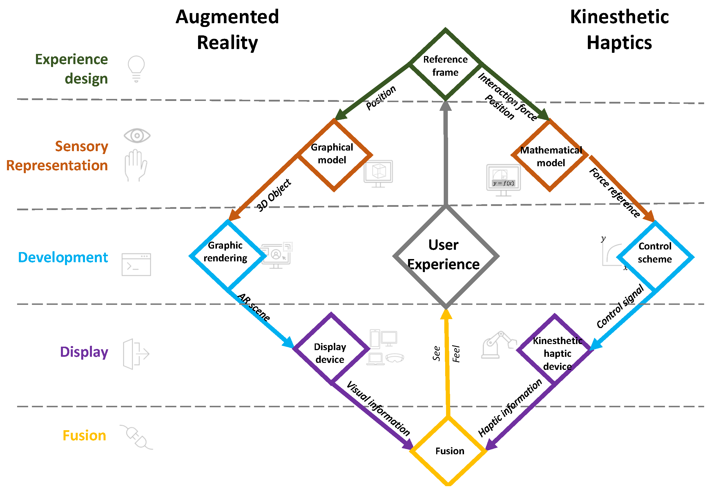
Figure 2.
Example of an reference frame
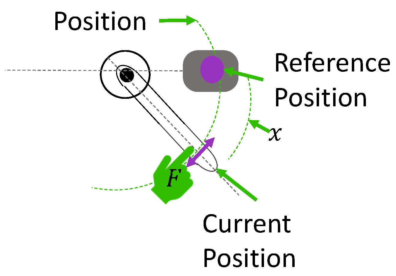
Figure 3.
References for tension virtual spring experiments
Figure 4.
Reference points and 3D object planned position
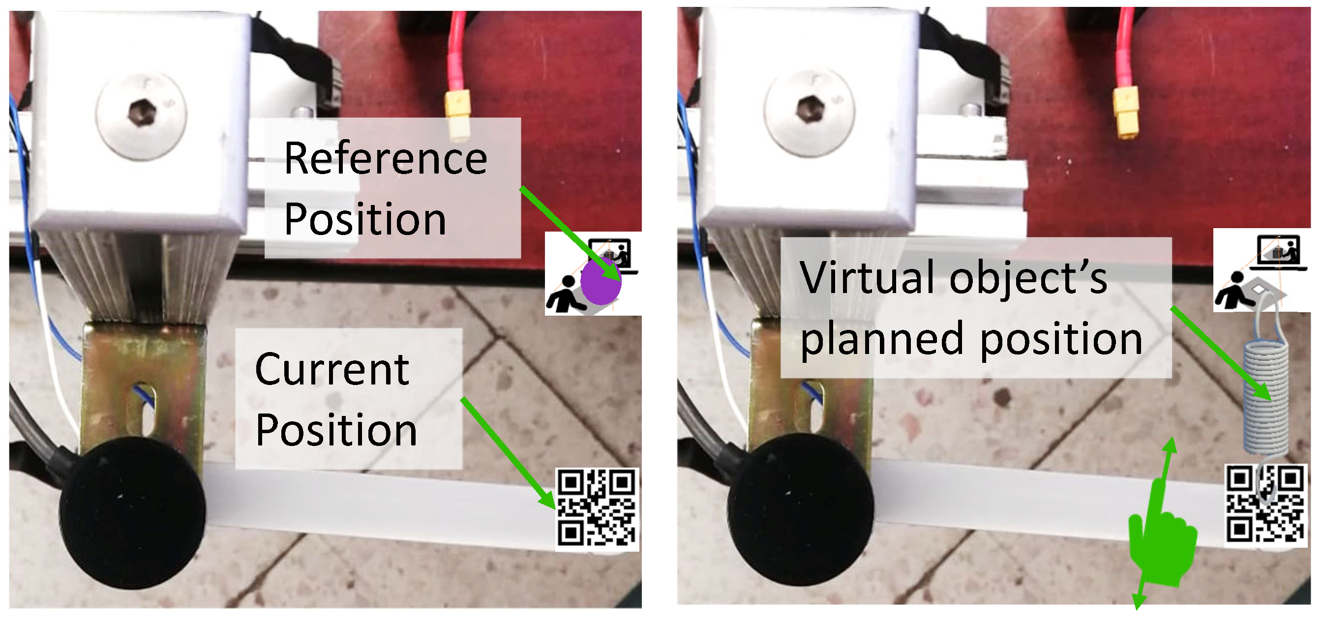
Figure 5.
tension virtual spring CAD
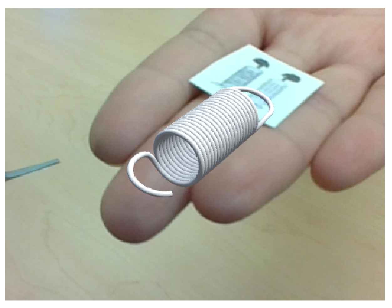
Figure 6.
Force interaction and moment arm
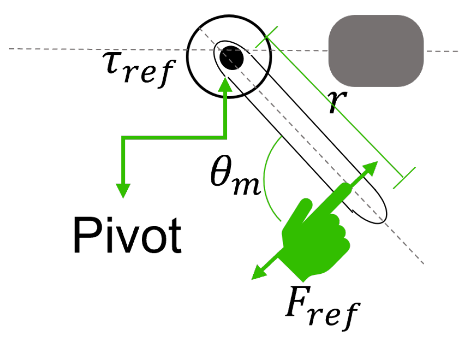
Figure 7.
Sensorless toque control scheme
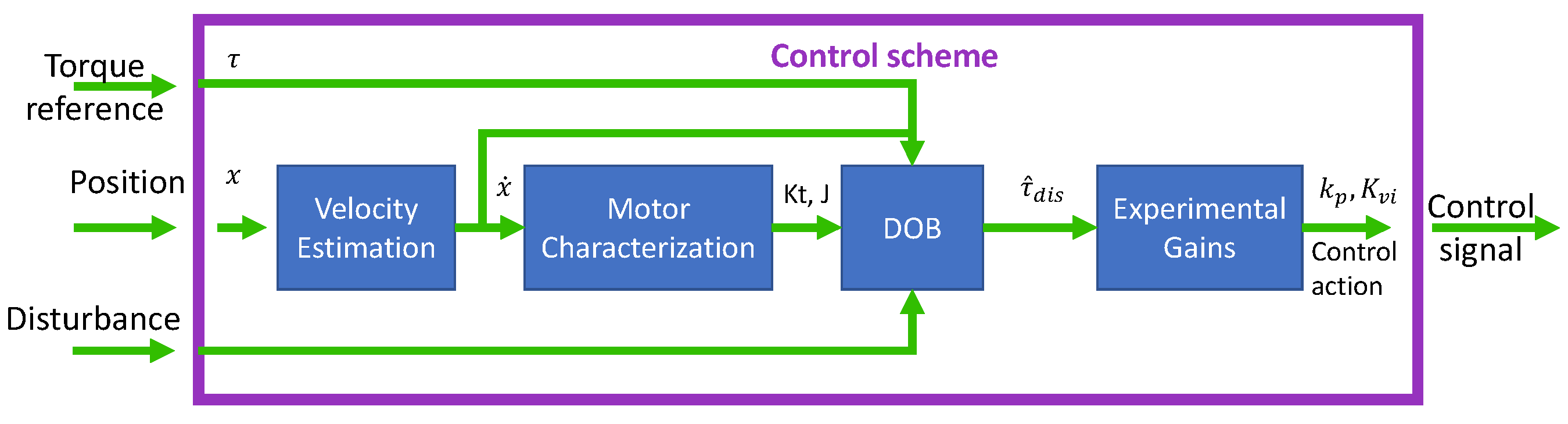
Figure 8.
Haptic information: user’s feeling of virtual spring. Simulation and experimental results, a) Experimental position when moving the Haptic Lever manually, b) Simulation of changing position at a constant velocity, c) Experimental results of the torque control response compared to the torque reference, and d) Simulation of the torque response given a simulated change in position
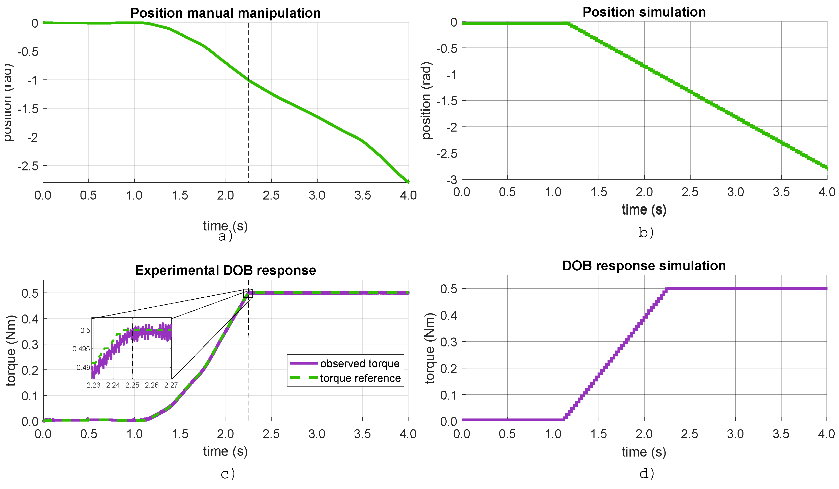
Figure 9.
Virtual spring scale transformation displayed
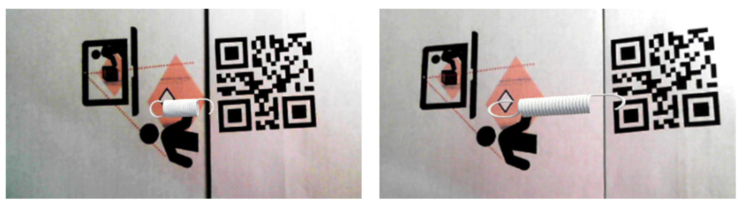
Figure 10.
Kinesthetic haptic interface: The Haptic Lever from [31]
Figure 10.
Kinesthetic haptic interface: The Haptic Lever from [31]
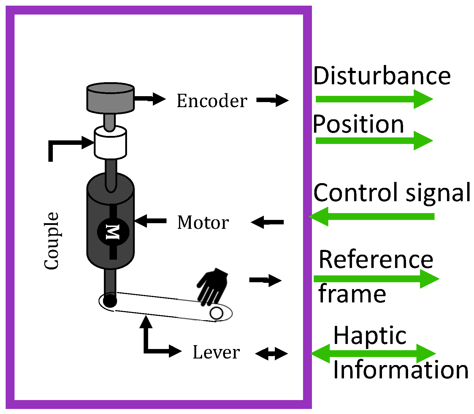
Figure 11.
Camera setup for marker-based tracking
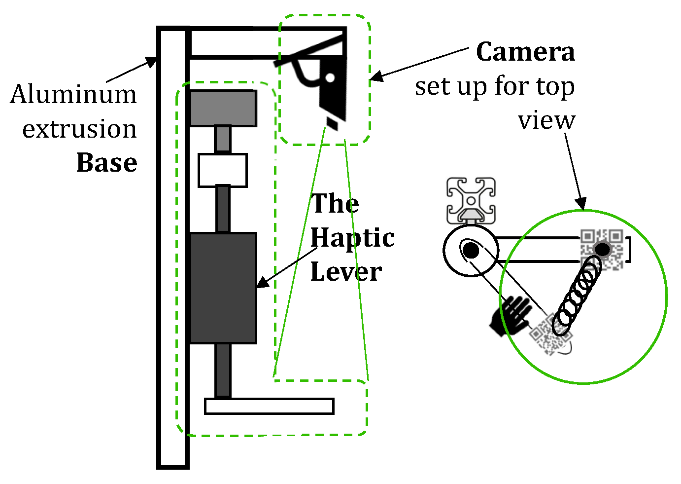
Figure 12.
Visual information fusion: user’s view of virtual spring
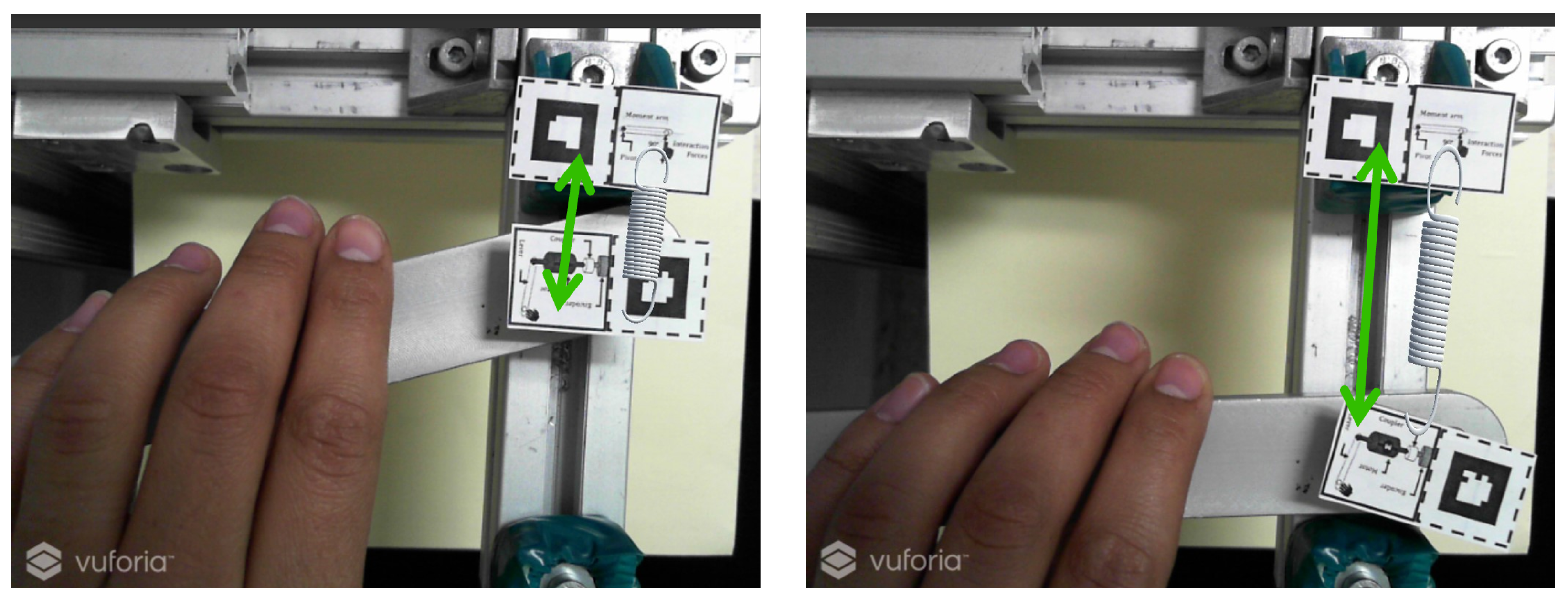
Figure 13.
Final experimental set for visual close loop interaction
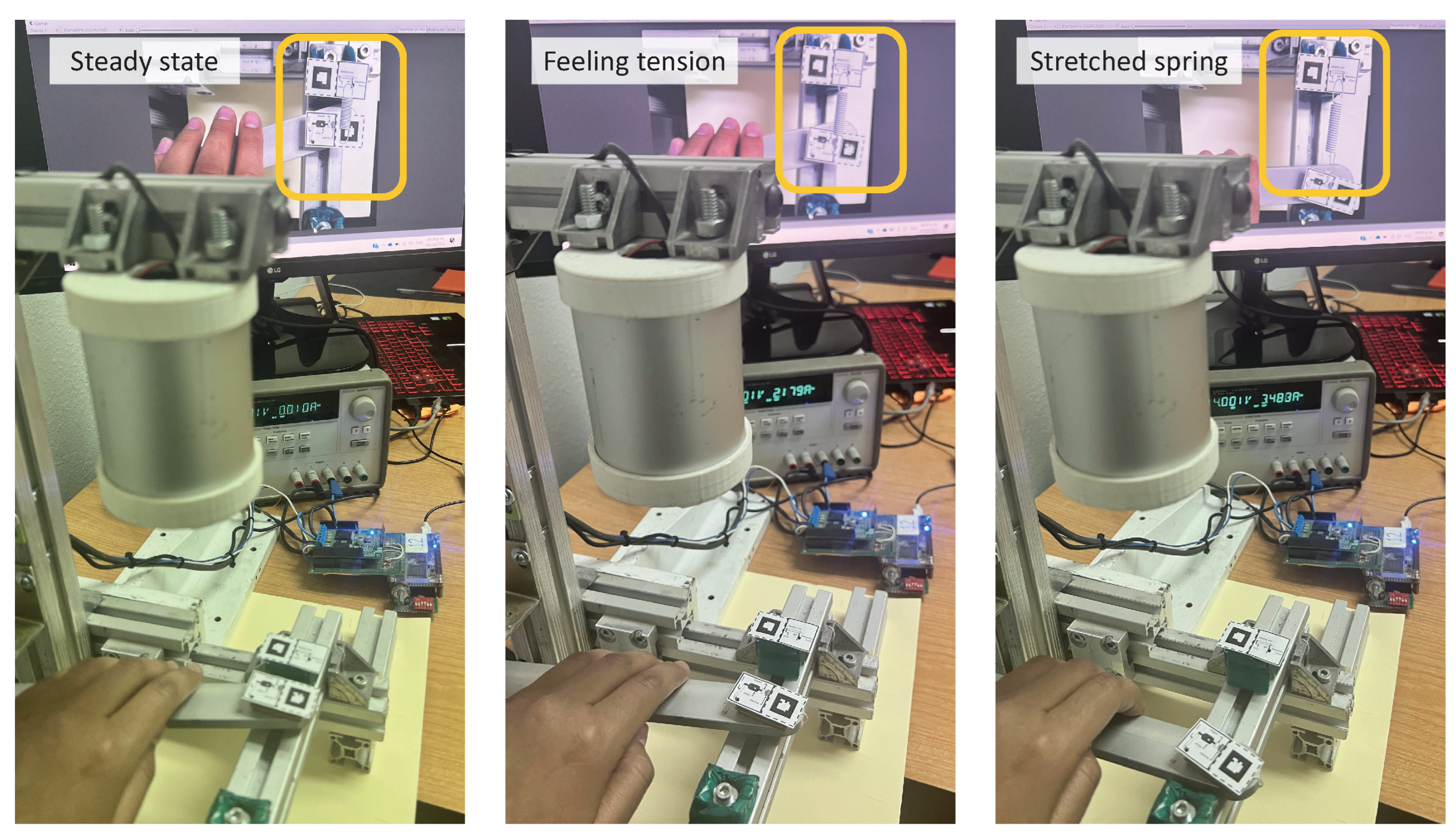

Table 1.
Example’s list of physical properties to feel
| Brittleness | Hardness | Pressure |
| Ductility | Magnetic field | Stiffness |
| Density | Magnetic flux | Tension |
| Elasticity | Mass | Viscosity |
| Electric charge | Momentum | Weight |
| Electric field | Plasticity |
Table 2.
Main variables of the reference frame
| Experience Variable | Description |
|---|---|
| Position | State of the interfaces that indicates the location of the lever throughout a trajectory. |
| Reference Position | Indicates the positioning of the virtual object in the AR environment. |
| Current Position | Indicates the location at the current time. |
| x | Relative position of the lever indicates the distance between the reference position and the current position. |
| F | Interaction force displayed by the haptic interface to the user, the two-sided arrow indicates that the direction may be on either way. |
| r | Moment arm taken from the length of the lever. |
| Torque exerted by the motor. |
Disclaimer/Publisher’s Note: The statements, opinions and data contained in all publications are solely those of the individual author(s) and contributor(s) and not of MDPI and/or the editor(s). MDPI and/or the editor(s) disclaim responsibility for any injury to people or property resulting from any ideas, methods, instructions or products referred to in the content. |
© 2024 by the authors. Licensee MDPI, Basel, Switzerland. This article is an open access article distributed under the terms and conditions of the Creative Commons Attribution (CC BY) license (http://creativecommons.org/licenses/by/4.0/).
Copyright: This open access article is published under a Creative Commons CC BY 4.0 license, which permit the free download, distribution, and reuse, provided that the author and preprint are cited in any reuse.


