
Submitted:
01 February 2024
Posted:
01 February 2024
You are already at the latest version
Abstract
The 1060 aluminium alloy is widely applied to electronic industry, construction area, aerospace field, traffic engineering, decoration and consumption goods market for its good chemical, physical and mechanical properties. In general, excellent processing property is necessary and important for manufacturing of complicated panels. In this paper, a special 2D ultrasonic vibration incremental forming method is designed to improve its plasticity and mechanical properties. Three kind of processing methods including traditional single point incremental forming, longitudinal ultrasonic vibration incremental forming and 2D ultrasonic vibration incremental forming are conducted for flexible manufacture of conical parts of 1060 aluminium alloy sheet. Then micro-hardness tests, residual stress tests and scanning electron microscopy tests are carried out to probe its revolution of micro-structure and mechanical properties and to analysis the effects of different types of ultrasonic vibration on plasticity and fracture characteristic of 1060 aluminium alloy. It is proved that 2D ultrasonic vibration is facilitated to improvement of plasticity and surface qualities of 1060 aluminium alloy than the other two processing methods. So, the novel 2D ultrasonic vibration incremental forming possesses substantial application values on flexible and rapid manufacturing of complicated thin-walled component of aluminium alloy.
Keywords:
Aluminium Alloy
; Incremental Forming
; Ultrasonic Vibration
; Plasticity
; Micro-morphology
; Residual Stress
1. Introduction
The 1060 aluminium alloy is widely applied to electronic industry, construction area, aerospace field, traffic engineering, decoration and consumption goods market due to its excellent chemical, physical and mechanical properties, such as high ductility, electrical conductivity, thermal conductivity and corrosion resistance [1]. It is not suitable to heat treatment strengthening, soldering and mechanical cutting. Plastic processing technology, like punching, wire drawing, extrusion or rolling, is one of the most frequently used method for manufacturing of the metal products. The most common products include but not limited to the following items: capacitor, gasket, isolation net of vacuum tube, protective cover of electrical cable, component of ventilation system of aircraft, heat-conducting element, radiator, hull parts of ship, metal handicraft, door and window decoration [2,3]. Obviously, there are huge market requirements for thin-walled components of 1060 aluminium alloy and their manufacturing technology.
Punching is a kind of plastic forming technology, including deep drawing, bending, spinning, hydraulic bulging, creep age forming, blanking and flanging, in which a metal sheet is deformed or detached under impact force exerted by a mould [4,5,6]. It is well known that mould-relied manufacturing mode could meet the high efficiency and contour consistency demands of mass production mode of single variety product. But it is not suitable for small amount production of multiple variety products due to its long manufacturing cycle and high manufacturing cost of mould. One kind of incremental forming technology is designed to satisfy the flexible manufacturing need of multiple variety products [7,8]. This mould-free manufacturing technology is that the metal sheet is extruded by a hemisphere tooling which feeds according to the contour lines of target product instead of a rigid mould with a molded surface. Convenient processing path programming could rapidly respond to the contour variation of the target products. Therefore, the flexible manufacturing technology has advantages in customized and rapid manufacturing as well as low-cost and improvement of technological properties of difficult-to-process metal materials.
In resent years, considerable research attentions have been focused on high-energy assisted plastic processing of metal materials. Large amounts of new manufacturing methods, such as ultrasonic cutting, ultrasonic laser processing and ultrasonic rolling, have been designed and the mechanical behaviors and micro-structure revolution of metal materials under multiple energy field conditions were researched [9,10,11,12,13,14]. A new two-step electromagnetic forming technology which combines electromagnetic forming with electromagnetic calibration is proposed by Su [15]. Khan [16] suggested an heat treatment and incremental forming processing route to produce age-hardened components with reasonable accuracy and formability. In addition, plenty of studies have suggested that ultrasonic vibration could decrease forming force, soften materials and improve contact friction conditions which are benefit for improvement of manufacturing qualities. Then, considerable attentions are focused on ultrasonic-assisting plastic forming technology. Yan Li [17] studied the influence of different vibration parameters on formability of 1060 Aluminium alloy sheet. In Liu Shen’s paper [18], ultrasonic vibration is imposed on the die to decrease the difficulties of drawing deformation of titanium wire at room temperature. The effect of longitudinal amplitude and frequency of ultrasonic vibration on deform force is investigated. And the research also indicates that the longitudinal and torsional composite vibration is effective for improvement of surface quality. Hu Jun [19] designed a 60 KHz longitudinal ultrasonic-assisted compression testing system and applied it for investigation of ultrasonic volume effects. Zhou Haiyang [20] studied on influence of frequencies and amplitudes of ultrasonic vibration on plasticity of aluminium and titanium. He found the ultrasonic softening effects could be enhanced by increasing the vibration amplitude. As so far, effects of ultrasonic vibration parameters, including frequency and amplitude, on mechanical behaviors and forming qualities of metal sheet have been investigated by several scholars and some research achievements have been published in the literature [21,22,23,24]. However, few research on influence of strengthening ultrasonic energy and multi-dimensional mode of vibration on mechanical performance and forming mechanism of metal materials have been reported. So, it is necessary to design a new enhanced ultrasonic vibration incremental forming technology and discover the softening action of high ultrasonic energy on metals.
For enhancement of volume effect and surface effect induced by ultrasonic energy and generated on metal materials, one kind of 2D ultrasonic vibration incremental forming method is used for manufacturing of conical components of 1060 aluminium alloy to research on its plastic deformation behaviors and fracture characteristic. The novel 2D ultrasonic vibration incremental forming experiment of conical workpiece of 1060 aluminium alloy and its contrast experiments are performed in this paper.
2. Materials and Methods
2.1. Experimental Materials
For its good usability and extensive applications in industries, 1060 aluminium alloy sheets are used for experimental research of manufacturing tests, performance measurements and mechanism analysis of conical components in this paper. Its chemical composition is list in Table 1.
2.2. Workpieces and Tools
Incremental forming is one kind of variant stamping technology for manufacturing of thin-walled component of metal materials. The rolling blank is cut to be semi-finished workpieces with three dimensional size of 80mm×80mm×2mm on wire electrical discharge machine. The workpieces and the mould are shown in Figure 1(a). Although this forming process is a free-mould manufacturing of thin-walled plates, an ordinary mould playing an supporting role is facilitated to improvement of forming qualities. The mould suffering impact is made of 45 steel with good rigidity and high strength. The combined mould is divided into two parts, including the fixture part and the core mould part. The core mould with replaceable-surface is fixed on the vibrated platform by the fixture part. Because of suffering coupling action of high temperature, violent strike and intense friction, the hemispherical forming tool is made of high temperature alloy of K25 as shown in Figure 1(b).
2.3. Method of Experiment
2.3.1. Processing Principle
In this paper, one kind of 2 dimension ultrasonic vibration device is applied to manufacturing of conical components of 1060 aluminium alloy. As Figure 2(a) shown, traditional single point incremental forming (SPIF) is a variant stamping of layered extrusion by utilizing motion path of rolling forming tool instead of traditional stamping mould. In Figure 2(b), the existing longitudinal ultrasonic vibration incremental forming (LUVIF) inherits flexible forming merits of SPIF technology. It also decreases forming force and improves surface qualities by virtue of volume effect and surface effect. Different the two former technologies, the new two-dimensional ultrasonic vibration incremental forming (2D-UVIF) method shown in Figure 2(c) consists of two ultrasonic vibration systems. On the one hand, the two-vibration-systems design which provides strengthening ultrasonic energy for softening difficult machining materials and decreasing forming force is facilitated to manufacturing of complicated thin-walled components of high strength alloys. On the other hand, its unique two-dimensional ultrasonic vibration motion is designed for increasing the contact areas between the metal part and the forming tool and improvement of the bad friction conditions between them. This is help for improvement of surface qualities and surface conditions including surface morphology, mechanical properties and stress state. It is known that high surface qualities and excellent surface conditions could enhance mechanical properties, decay resistance and fatigue resistance performance.
2.3.2. Processing Equipment
To complete manufacturing tests of conical components of 1060 aluminium alloy for 2D ultrasonic vibration incremental forming, a new 2D ultrasonic vibration auxiliary device is designed and manufactured. It includes a h-shape base, one X-axis ultrasonic vibration system, one Z-axis ultrasonic vibration system and a vibration platform. Each ultrasonic vibration system contains a signal generator, a signal amplifier and a ultrasonic horn. The signal generator launches a ultrasonic wave signal that is amplified by the amplifier. Then, the strengthening signal drives the horn to vibrate. As Figure 3 shown, two crossed ultrasonic vibration systems, the vibrating direction of one system is parallel to the axis of the forming tool and the vibrating direction of the other one is perpendicular to the axis of the forming tool, are connected to the platform. The part is derived to vibrating in a circle track relative to the forming tool while the two ultrasonic vibration devices vibrate at the same frequency and amplitude and the phase difference of the two signal waves is one quarter.
In addition, the vibrating track of the compound ultrasonic vibration device is editable according to processing requirements. For example, its vibrating track is a ellipse if the two ultrasonic vibration devices vibrate at the same frequency and different amplitude and their phase difference is a quarter. Besides, non-vibration mode, one-way horizontal vibration mode, one-way vertical vibration mode and compound diagonal vibration mode are also realizable.
As Figure 3(b) shown, the 2D ultrasonic vibration auxiliary device is fixed on the workbench of a four axis CNC machining center. A fixture and a conical-surface mould are installed on the vibrated platform of 2D ultrasonic device. Besides, a hemispherical tooling is designed for replacing the traditional milling tooling. Then, the universal milling machine is transformed to be a specialized 2D ultrasonic vibration incremental forming machine.
2.3.2. Processing Conditions
The manufacturing experiments of conical workpieces of 1060 aluminium alloy for traditional incremental forming, longitudinal vibration incremental forming and 2D ultrasonic vibration incremental forming are performed. Firstly, blank sheet of 1060 aluminium alloy is installed on the conical mold. Secondly, processing procedure is developed and loaded in the operating system of the specialized incremental forming machine. Thirdly, tool-setting is complete accurately and then the workpiece coordinate system is established. Fourthly, processing parameters are set in the operating system. The hemispherical forming tool feeds horizontally at a constant velocity of 500 mm/min and feeds vertically at a layer depth of 0.1mm as well ass rotating at speed of 500 r/min. Lastly, the cooling system and the ultrasonic vibration system are opened. Then, the traditional incremental forming, the longitudinal vibration incremental forming and the 2D ultrasonic vibration incremental forming tests are performed automatically by the processing program. Three conical parts processed by traditional single point incremental forming, longitudinal ultrasonic vibration incremental forming and 2D ultrasonic vibration incremental forming are shown in Figure 4.
3. Results and Discussion
Three conical components are manufactured separately by using the traditional single point incremental forming, the longitudinal ultrasonic vibration incremental forming and 2D ultrasonic vibration incremental forming technology. To investigate the effect of new designed 2D ultrasonic vibration method on the mechanical behaviors and forming mechanism of 1060 aluminium alloy, micro-hardness tests, residual stress tests and scanning electron microscope observation tests of fracture surface of conical components are conducted.
3.1. Micro Mechanical Properties
It is well known that surface hardness is one of the most important mechanical properties of metal materials. Micro-hardness test is widely used for mechanical properties detection of raw materials, semi-finished or finished product because of this non-destructive testing approach is unlimited to shape and size of detected object. And hardness is always closely associated with strength and toughness of metal materials. For detecting mechanical properties of 1060 aluminium alloy sheets for traditional single point incremental forming, longitudinal ultrasonic vibration incremental forming and 2D ultrasonic vibration incremental forming, a series of micro-hardness tests are performed on the HAMS automatic Vickers microhardness testing system. A right square pyramid diamond indenter is pressed on surface of detected object with testing pressure of 2.9N and testing time of 15s. Hardness value is calculated automatically by dividing the pressure by the area of the testing square cone indentation showed in the Figure 5(b). As present in the Figure 5(a), there are ten sampling points located equidistantly and equiangularly in a helix line on the inside wall of the conical component processed by traditional single point incremental forming, longitudinal ultrasonic vibration incremental forming and 2D ultrasonic vibration incremental forming technology. Simultaneously, ten sampling points randomly distributed on surface of 1060 aluminium alloy sheet are detected. All the testing microhardness value are showed in Figure 5(c). The black square points represent surface microhardness values of unprocessed 1060 aluminium alloy sheet. The blue rhombus points represent surface microhardness values of conical component for 2D ultrasonic vibration incremental forming. The green circle points represent surface microhardness values of conical component for traditional single point incremental forming. The red star points represent surface microhardness values of conical component for longitudinal ultrasonic vibration incremental forming.
Despite few data outliers exist on the four curves, it is clear that the influence of different processing technology on surface mechanical properties of 1060 aluminium alloy is totally distinct. As Figure 6(c) shown, the surface hardness values of the unprocessed 1060 aluminium alloy sheet are minimum. Their mean value and variance are 39.85 HV and 1.37. Those testing data demonstrate that the mechanical properties of 1060 aluminium alloy are poor and large-scale industrial process provides good consistency in processing quality and mechanical properties. The maximum values are red circle points represent surface hardness of conical component for longitudinal ultrasonic vibration incremental forming. Some researches in this field indicate that ultrasonic incremental forming generally produces coupling actions of ultrasonic softening, ultrasonic hardening, stress superposition, heat softening and work hardening on metal materials. Obviously, longitudinal ultrasonic vibration, on the one hand, provides high-frequency impact on surface of aluminium alloy sheet. On the other hand, it creates softening action inside of metal materials which is conducive to increase its plasticity. Their mean value and variance are 84.60 HV and 14.21. Testing results prove that hardening dominates on surface of the conical part because of longitudinal impact and cold-formed process. And the impact hardening actions are heterogeneously distributed, so the red curve features of poor consistency. The green curve is lower than red one. Its mean value and variance are 61.50 HV and 7.93. The main reason is that traditional single point incremental forming only produces work-hardening effect. The blue curve indicates that the 2D ultrasonic vibration creates strengthening softening effect on surface of aluminium alloy part. Ultrasonic softening, stress superposition and heat softening counteract ultrasonic hardening and work hardening. Some testing hardness value even lower than that of the unprocessed 1060 aluminium alloy sheet can prove this opinion. The two dimension vibration exerted on the poor rigid sheet doesn’t provide impact hardening on surface of the processed part. At last, the lower main value of 42.82 HV and variance of 5.12 manifest that softening dominates on surface of 1060 alloy and 2D vibration creates uniform mechanical effect on its processed surface.
3.2. Residual Stress Analysis
In order to probe the distribution and magnitude of residual stress field on processed surface of conical components for traditional single point incremental forming, longitudinal ultrasonic vibration incremental forming and 2D ultrasonic vibration incremental forming, three sets of residual stress tests are performed on i-XRD residual stress analysis system. The measurement conditions are list in Table 2.
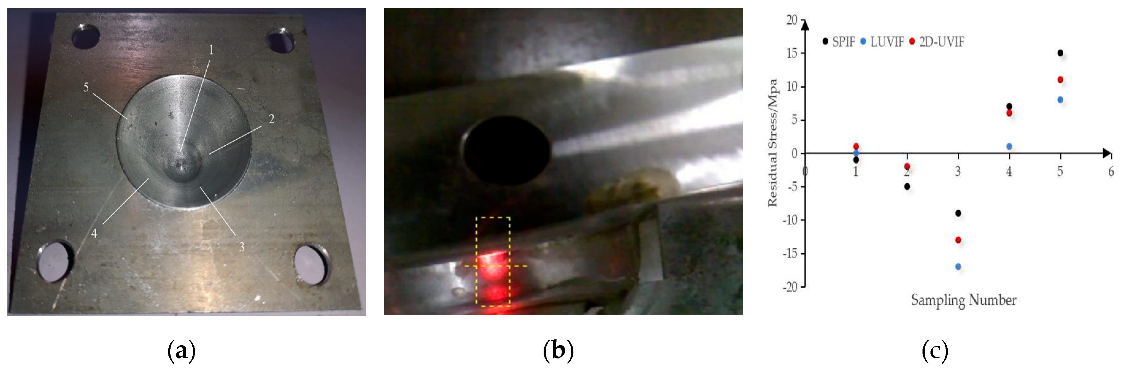
There are 5 sampling points located equidistantly and equiangularly in a helix line on the inside wall of each processed component. The sampling points are shown in Figure 6(a). Then these sampling locations are stamped with distinguishing marks and probed on i-XRD residual stress system. The testing procedure is demonstrated in Figure 6(b). The main advantage of this sampling method is that it obtains more extensive information characteristics, including different depth direction and circumference direction, from the processed surface of the conical part by using few sampling points.
Three sets of residual stress testing results are displayed in Figure 6(c). In this image, numbers on the horizontal axis represent sampling point numbers and numbers on the longitudinal axis represent residual stress value. Positive value indicates residual tensile stress and negative value indicates residual compressive stress. Those three groups of 15 data points are marked with different colors. The black points, the blue points and the red points represent respectively residual stress value on surface of conical parts for traditional single point incremental forming, longitudinal ultrasonic incremental forming and 2D ultrasonic vibration incremental forming. It is indicated that residual stress distribution on surface of the three components are of distinct patterns. Firstly, residual stress at locations of number 5 and number 4 which close to top of conical parts are tensile. Secondly, residual stress at position of number 3 which located in the middle of conical part are compressive. It is deduced that the combined action of the mould and the forming tool provides strong impact on processed surface. And the ultrasonic energy enhance this impact action. So, larger residual compressive stress distributed on surface of conical part for longitudinal ultrasonic incremental forming and 2D ultrasonic vibration incremental forming. Obviously, the longitudinal ultrasonic vibration produce more impact hardening than 2D ultrasonic vibration. Thirdly, residual stress field at the bottom of conical part has fallen close to zero. It is inferred that the unmatched-size forming tool couldn’t reach the bottom of the conical part. Therefore, there are no impact hardening in this area. In brief, these three forming technology only produce residual compressive stress in local area of processed surface.
Figure 6.
Sampling method and residual stress tests of conical part. (a) Sampling points on processed surface; (b) Residual stress test procedure; (c) Residual stress testing results.
Figure 6.
Sampling method and residual stress tests of conical part. (a) Sampling points on processed surface; (b) Residual stress test procedure; (c) Residual stress testing results.
3.3. Microstructure Images of Fracture Surface
It is believed that surface quality of processed part is not only concerned with its aesthetics, but also related to its fatigue life and structure safety. Surface micro- morphology of 1060 aluminium alloy sheet, conical parts for single point incremental forming, longitudinal ultrasonic vibration incremental forming and 2D ultrasonic vibration incremental forming are probed with scanning electronic microscope (SEM) technology. Their micro-structure images are shown in Figure 7. Firstly, Figure 7(a)-(c) show the micro-morphology of the unprocessed surface of 1060 aluminium alloy sheet. Three different magnification images indicate that it features smooth surface as well as some tiny and slight rolling indentations. Figure 7(d)-(f) show the surface micro-morphology of the conical part for single point incremental forming. A considerable amount of distinct indentations appear on its surface. It is reasonable to assume that the damage is related to the rapidly rotating forming tool which exert strong force on the part. This intense extruding force produces huge deformation as well as friction damage. In general, it is well known that ultrasonic vibration induces surface effect which could improve friction conditions between forming tool and processed part. This opinion is proved by Figure 7(g)-(i). There are much less friction marks appear on its surface compared to Figure 7(d)-(f). However, an obvious scratch is found in Figure 7(i). It is deduced that some particles detach from alloy sheet due to strong extrusion and fall into processing area between the sheet and the forming tool. Then, these hard solid scratches the processed surface under pressure and friction of rotating forming tool. Meanwhile, the longitudinal vibration of the forming tool intensifies this phenomenon. In Figure 7(j)-(l), few inconspicuous scratches are observed on the conical part for 2D ultrasonic vibration incremental forming. This is mainly due to the new designed 2 dimensional ultrasonic vibration. Although, there are still a lot of detached particles adhered on its surface. On the one hand, the strengthening surface effect is conducive to improve friction conditions between the part and the tool. On the other hand, its unique vibrating design is helpful for deriving those particles away from the processing area. So, it avoids such scratching behaviors caused by hard particles which are driven by the rapidly rotating forming tool. In a word, it is proved that the 2D ultrasonic forming takes more advantages in improvement of surface qualities than the other two methods.
It is generally accepted that micro-morphology characteristics of fracture surface contains abundant information about mechanical behaviors, deformation and fracture. As Figure 8(a)-(c) shown, few small and superficial dimples are found on fracture surface of conical part for traditional single point incremental forming. This ductile fracture feature indicates that 1060 aluminium alloy is of good plasticity. However, its limited plastic deformation capacity prevents the development of these dimples. The small dimples have no chance to grow up and then break. These adjacent dimples finally form a tearing ridges. In Figure 8(d)-(f), some large-size dimples of 20μm in diameter appear on fracture surface of conical part for longitudinal ultrasonic vibration incremental forming. It is inferred that volume effect induced by ultrasonic energy greatly enhance its plastic deformation capacity. So, the micro-dimples grow up and aggregate to become a large dimple. Meanwhile, some secondary phase particles detach from fracture surface. Besides, a evident hardening layer is found on the processed surface. This phenomenon is consistent with the micro-hardness testing results. As the increment of plastic deformation, some short cracks create on fracture surface. In Figure 8(g)-(i), there are much more isometric and huge dimples of 10-20μm in diameter appearing on fracture surface of conical part for 2D ultrasonic vibration incremental forming. It proves that the strengthening ultrasonic vibration design is beneficial to improve the plastic deformation property of 1060 aluminium alloy. When the forming tool exert mechanical force and ultrasonic energy on the metal materials, plentiful of micro-dimples create. And the adjacent dimples grow up to become a big dimple. Some small dimples hide around the big ones. At the same time, some secondary phase particles discover or detach from the original locations. Because of its good ductile, there are few short cracks observed on fracture surface.
4. Conclusions
In this paper, one kind of 2D ultrasonic vibration incremental forming is applied for manufacturing of conical part of 1060 aluminium alloy. Compared to the traditional single point incremental forming and the longitudinal ultrasonic vibration incremental forming, this novel forming technology inherits flexible manufacturing merits of incremental forming. Besides, it also takes remarkable advantages in improvement of processing performance and surface qualities. Testing results indicate that strengthening ultrasonic energy is helpful for outstanding improvement of plastic deformation capacity of 1060 aluminium alloy and the two dimension vibrating design could greatly ameliorate friction conditions between the forming tool and the processed part. In conclusion, this research proves that the novel 2D ultrasonic vibration incremental forming is suitable for rapid manufacturing of complicated component of 1060 aluminium alloy.
Author Contributions
Conceptualization, Y.L.; Methodology, Y.L.; Investigation, Y.L.; Writing Original Draft, Y.L.; Supervision, Y.L.; Funding acquisition, Y.L.; Data Curation, Yf.W. and M.D.; Visualization, Yf.W.; Writing-Review & Editing, Y.L. and Yf.W.; Resources, X.P.; Project administration, C.Y. and Y.W.. All authors have read and agreed to the published version of the manuscript.
Funding
This research was funded by the National Natural Science Foundation of China (Grant Number 52005399).
Institutional Review Board Statement
Not applicable.
Informed Consent Statement
Not applicable.
Data Availability Statement
All the data are available within the manuscript.
Conflicts of Interest
The authors declare no conflict of interest.
References
- Z.J. Wang; M. Ma; Z.X. Qiu; J.X. Zhang; W.C. Liu. Microstructure, texture and mechanical properties of AA 1060aluminum alloy processed by cryogenic accumulative roll bonding. Mater Charact. 2018, 139, 269-278. [CrossRef]
- Q.W. Xu; C.H. Qiang; C. W. Guo. Experimental study on the surface roughness of 1060 aluminum alloy cut by abrasive water Jet. Msf. 2019, 950, 32-37. [CrossRef]
- Z. Yu; A. Du; C. Wang; R. Ma; X. Cao. Incorporation mechanism of ZnO nanoparticles in PEO coating on 1060 Al alloy. Surf. Coat. Technol. 2021,412. [CrossRef]
- A.T. Shivank; B. Neha; V. Prashant; M. Smriti. Improving surface hardness of aluminum 6063 alloy using hardfacing. Mater. Today 2020. [CrossRef]
- Z.L. Yuan; L. Geng; N.N. Wang; T. Wu; W. Qi; Y.H. Dai; J.Q. Huang. Topology optimization method of stamping structures based on the directional density field. Materials. 2024, 17(3), 656. [CrossRef]
- L.H. Zhan; H. Xie; Y.L. Yang; S. Zhao; Z.L. Chang; Y.N. Xia; Z.Y. Zheng; Y.J. Zhou. Investigation on creep deformation and age strengthening behavior of 304 stainless steel under high stress levels. Materials. 2024, 17(3), 642. [CrossRef]
- J. R. Duflou, A. M. Habraken, J. Cao. Single point incremental forming:state-of-the-art and prospects. Int. J. Mater. 2017, 11(6), 743-773. [CrossRef]
- F. Maqbool; M. Bambach. Dominant deformation mechanisms in single point incremental forming(SPIF) and their effect on geometrical accuracy. Int. J. Mech. Sci. 2018, 136, 279–292. [CrossRef]
- C. Shi; K. Shen. Twin-roll casting 8011 aluminium alloy strips under ultrasonic energy field. Int. J. Light.Mater. Manuf. 2018, 1, 108-114. [CrossRef]
- Y.L. Yang; Z.L. Liu; R.P. Jiang; R.Q. Li; X.Q. Li. Microstructural evolution and mechanical properties of the AA2219/TiC nanocomposite manufactured by ultrasonic solidification. J. Alloy. Compd. 2019. [CrossRef]
- H. Puga; J. Barbosa; J. Machado; C. Vilarinho. Ultrasonic grain refinement of die cast copper alloys. J. Mater.Process. Technol. 2019, 263, 336-342. [CrossRef]
- J. Huang; J. Li; C. Li; C. Huang; B. Friedrich. Elimination of edge cracks and centerline segregation of twin-roll cast aluminum strip by ultrasonic melt treatment. J. Mater. Res. Technol. 2020. [CrossRef]
- Y. Tian; Z.L. Liu; X.Q. Li; R.Q. Li; L.H. Zhang; R.P. Jiang; F. Dong. The cavitation erosion of ultrasonic sonotrode during large-scalemetallic casting: Experiment and simulation. Ultrason. Sonohem. 2018, 37, 29-37. [CrossRef]
- C. Shi; Y.J. Wu; D.H. Mao; G.F. Fan. Effects of ultrasonic bending vibration introduced by an L-shaped ultrasonic rod on the microstructure and properties of a 1060 aluminum alloy strip formed by twin-roll casting. Materials. 2020. [CrossRef]
- H. Su; L. Huang; J. Li; F. Ma; P. Huang; F. Feng. Two-step electromagnetic forming: a new forming approach to local features of large-size sheet metal parts. Int J Mach Tool Manu. 2018, 124, 99–116. [CrossRef]
- S. Khan; G. Hussain; M. Ilyas; H. Rashid; M. I. Khan; W. A. Khan. Appropriate heat treatment and incremental forming route to produce age-hardened components of Al-2219 alloy with minimized form error and high formability. J Mater Process Technol. 2018, 256, 262-273. [CrossRef]
- S. M. Yang; L. Bai; Y. Li; Q. Yuan. Influences of vibration parameters on formability of 1060 aluminum sheet processed by ultrasonic vibration-assisted single point incremental forming. Adv Mater Sci Eng, 2019. [CrossRef]
- S. Liu; X. Shan; K. Guo; Y. Yang; T. Xie. Experimental study on titanium wire drawing with ultrasonic vibration. Ultrasonics. 2018, 83, 60-67. [CrossRef]
- H. Jun; S. Tetsuhide; Y. Ming. Investigation on ultrasonic volume effects: stress superposition, acoustic softening and dynamic impact. Ultrason Sonochem. 2018, 48, 240-248. [CrossRef]
- H. Zhou; H. Cui; Q. H. Qin. Influence of ultrasonic vibration on the plasticity of metals during compression process. J Mater Process Technol. 2018, 251, 146-159. [CrossRef]
- Y. Li; X. Chen; J. Sun; J. Li; G. Zhao. Effects of ultrasonic vibration on deformation mechanism of incremental point forming process. Procedia Eng. 2017, 207, 777-782. [CrossRef]
- S. Amini; A. H. Gollo; H. Paktinat. An Investigation of conventional and ultrasonic-assisted incremental forming of annealed AA1050 sheet. Int J Adv Manuf Tech. 2016, 90, 1569-1578. [CrossRef]
- P. Li; J. He; Q. Liu. Evaluation of forming forces in ultrasonic incremental sheet metal forming. Aerosp Sci Technol. 2017, 63, 132-139. [CrossRef]
- T. Obikawa; M. Hayashi. Ultrasonic-assisted incremental microforming of thin shell pyramids of metallic foil. Micromachines, 2017, 8(5), 142-152. [CrossRef]
Figure 1.
Devices for incremental forming: (a) Mould and specimen; (b) Forming tool.
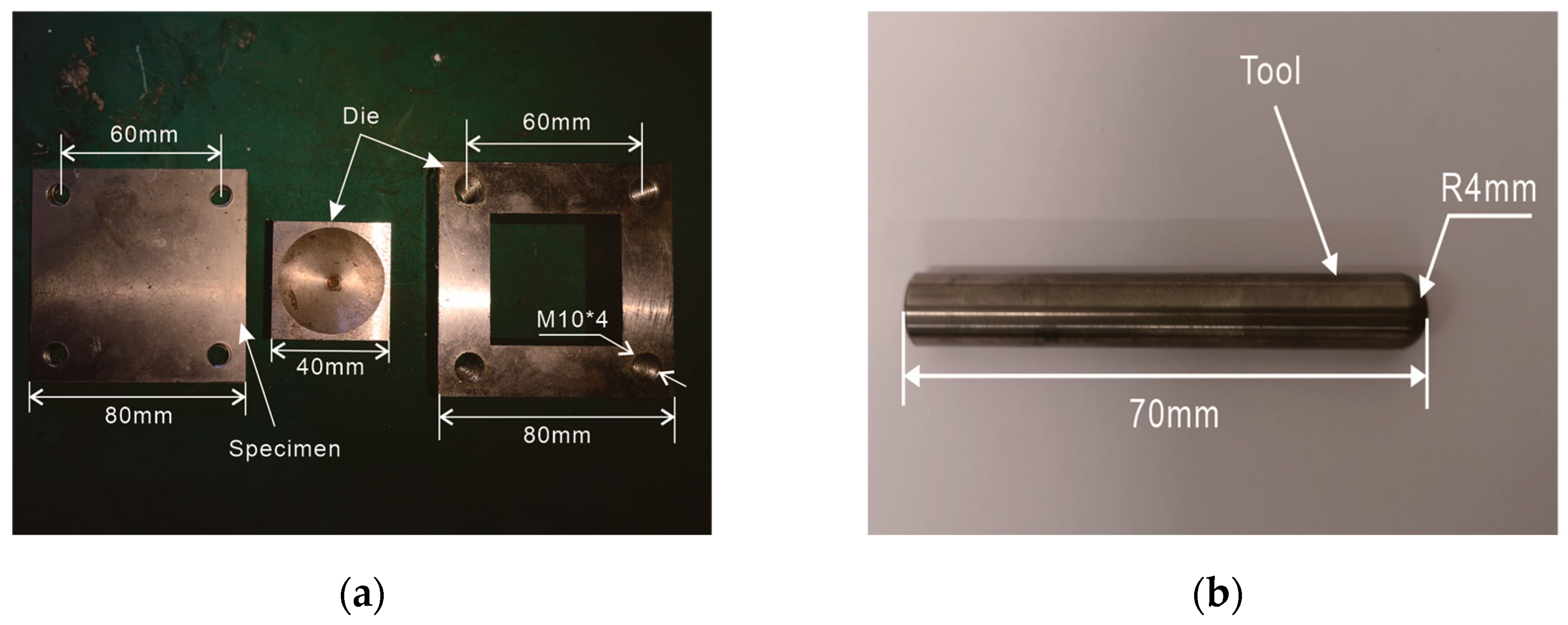
Figure 2.
Processing principle of three forming technology: (a) Traditional single point incremental forming (SPIF); (b) Longitudinal ultrasonic vibration incremental forming (LUVIF); (c) 2D ultrasonic vibration incremental forming (2D-UVIF).
Figure 2.
Processing principle of three forming technology: (a) Traditional single point incremental forming (SPIF); (b) Longitudinal ultrasonic vibration incremental forming (LUVIF); (c) 2D ultrasonic vibration incremental forming (2D-UVIF).
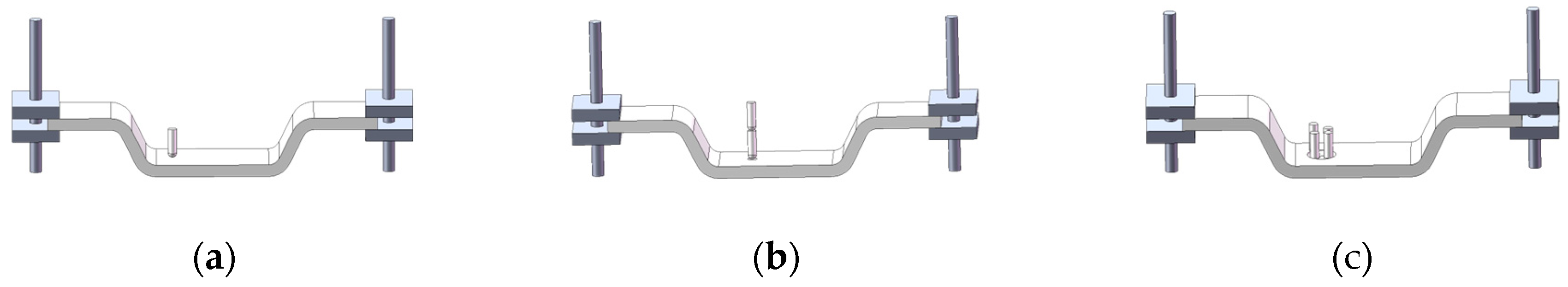
Figure 3.
A specialized ultrasonic vibration incremental forming machine: (a) Schematic design of 2D ultrasonic vibration system; (b) 2D ultrasonic vibration device.
Figure 3.
A specialized ultrasonic vibration incremental forming machine: (a) Schematic design of 2D ultrasonic vibration system; (b) 2D ultrasonic vibration device.
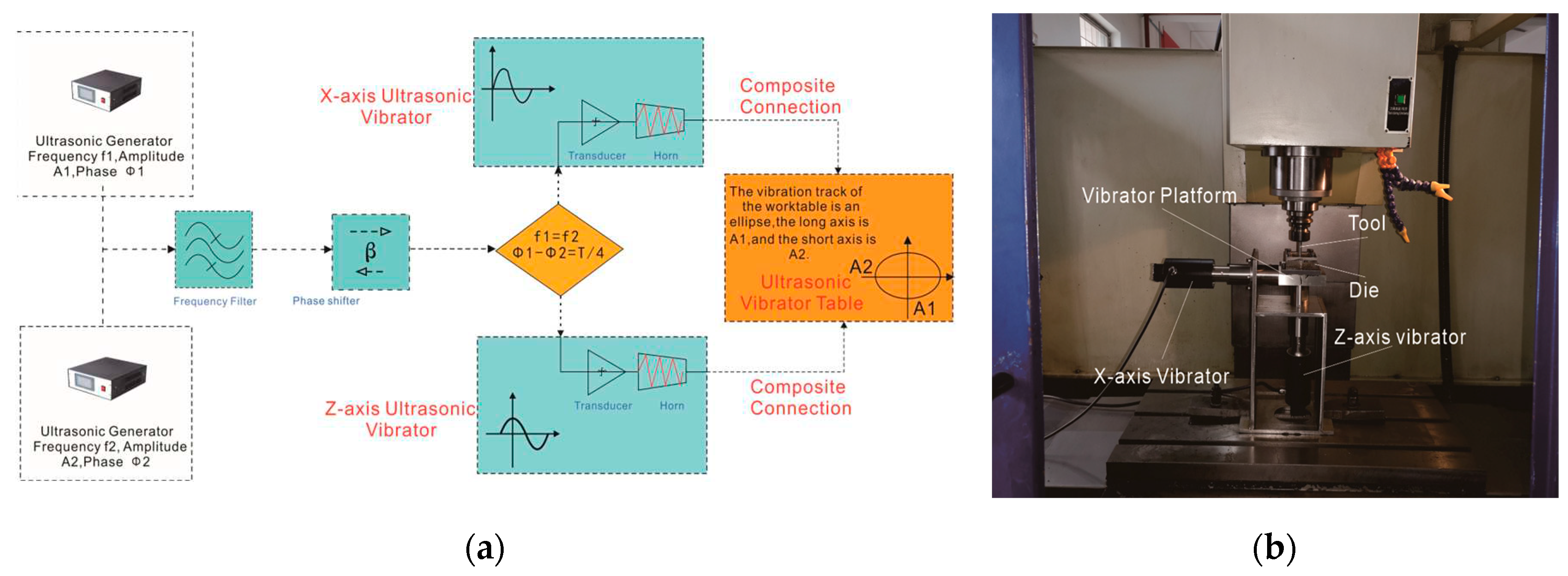
Figure 4.
Processed parts. (a) SPIF part; (b) LUVIF part; (c) 2D-UVIF part.
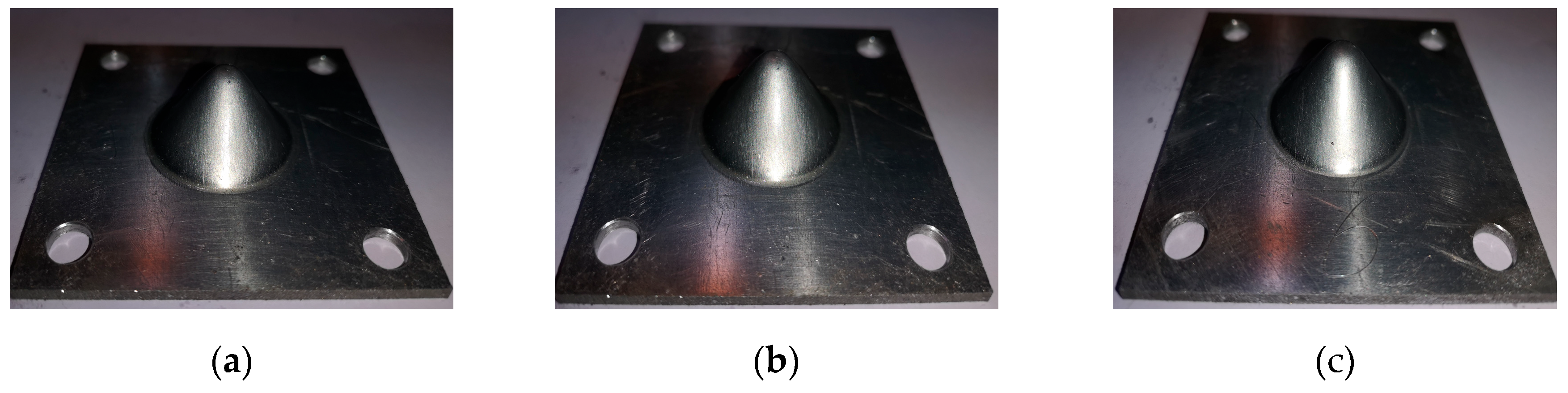
Figure 5.
Micro-hardness tests: (a) Sampling locations on the conical component (Ten testing points located equidistantly and equiangularly in a helix line on inside wall of conical component); (b) Micro-hardness testing images (Image from the top left corner to the bottom right corner respectively shows the testing square cone indentation on surface of 1060 aluminium alloy sheet, SPIF part, LUVIF part and 2D-UVIF part); (c) Micro-hardness curves.
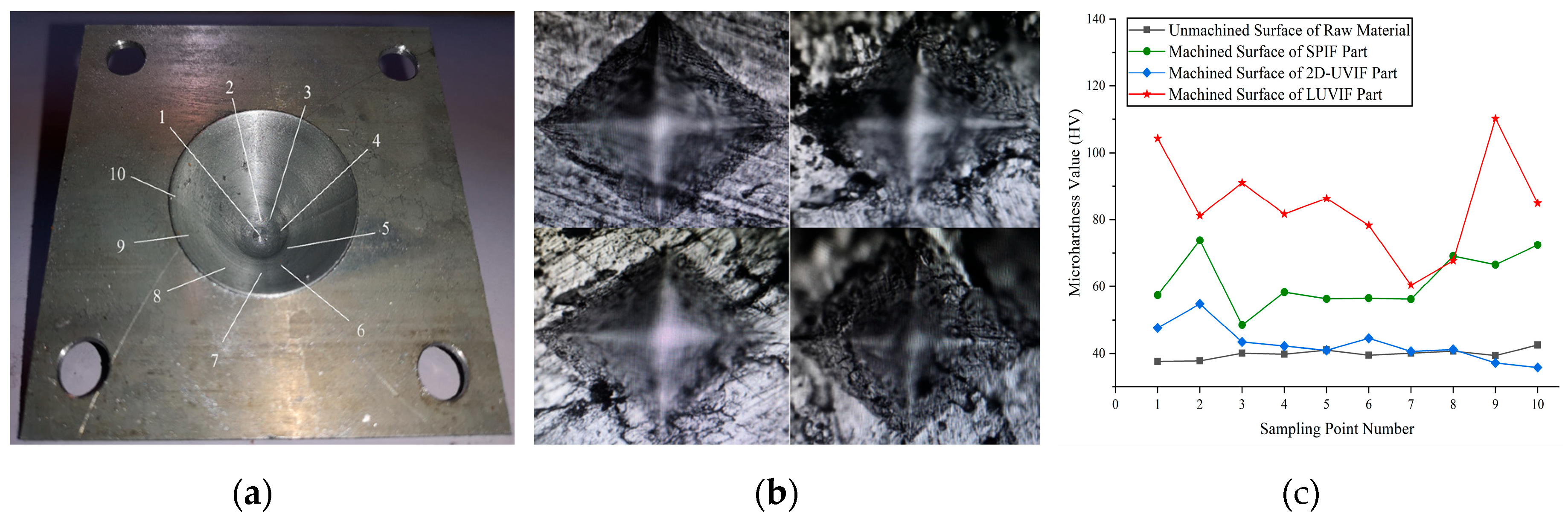
Figure 7.
Magnification images of surface morphology of 1060 aluminium alloy sheet, SPIF part, LUVIF part and 2D-UVIF part. (a) 500×, 1060 sheet; (b) 1000×, 1060 sheet; (c) 2000×, 1060 sheet; (d) 500×, SPIF; (e) 1000×, SPIF; (f) 2000×, SPIF; (g) 500×, LUVIF; (h) 1000×, LUVIF; (i) 2000×, LUVIF; (j) 500×, 2D-UVIF; (k) 1000×, 2D-UVIF; (l) 2000×, 2D-UVIF.
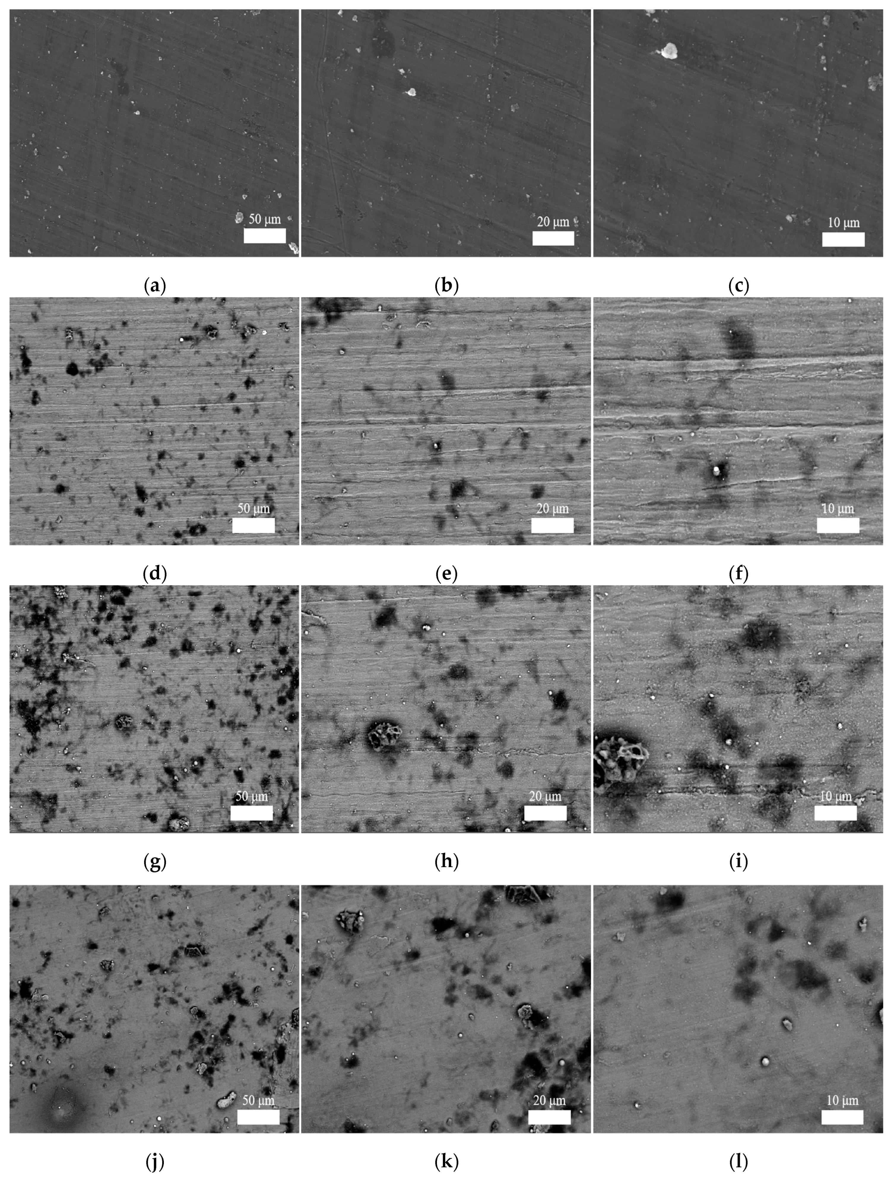
Figure 8.
Micro-morphology images of fracture surface of the conical parts for SPIF, LUVIF and 2D-UVIF. (a) 500×, SPIF; (b) 1000×, SPIF; (c) 2000×, SPIF; (d) 500×, LUVIF; (e) 1000×, LUVIF; (f) 2000×, LUVIF; (g) 500×, 2D-UVIF; (h) 1000×, 2D-UVIF; (i) 2000×, 2D-UVIF.
Figure 8.
Micro-morphology images of fracture surface of the conical parts for SPIF, LUVIF and 2D-UVIF. (a) 500×, SPIF; (b) 1000×, SPIF; (c) 2000×, SPIF; (d) 500×, LUVIF; (e) 1000×, LUVIF; (f) 2000×, LUVIF; (g) 500×, 2D-UVIF; (h) 1000×, 2D-UVIF; (i) 2000×, 2D-UVIF.
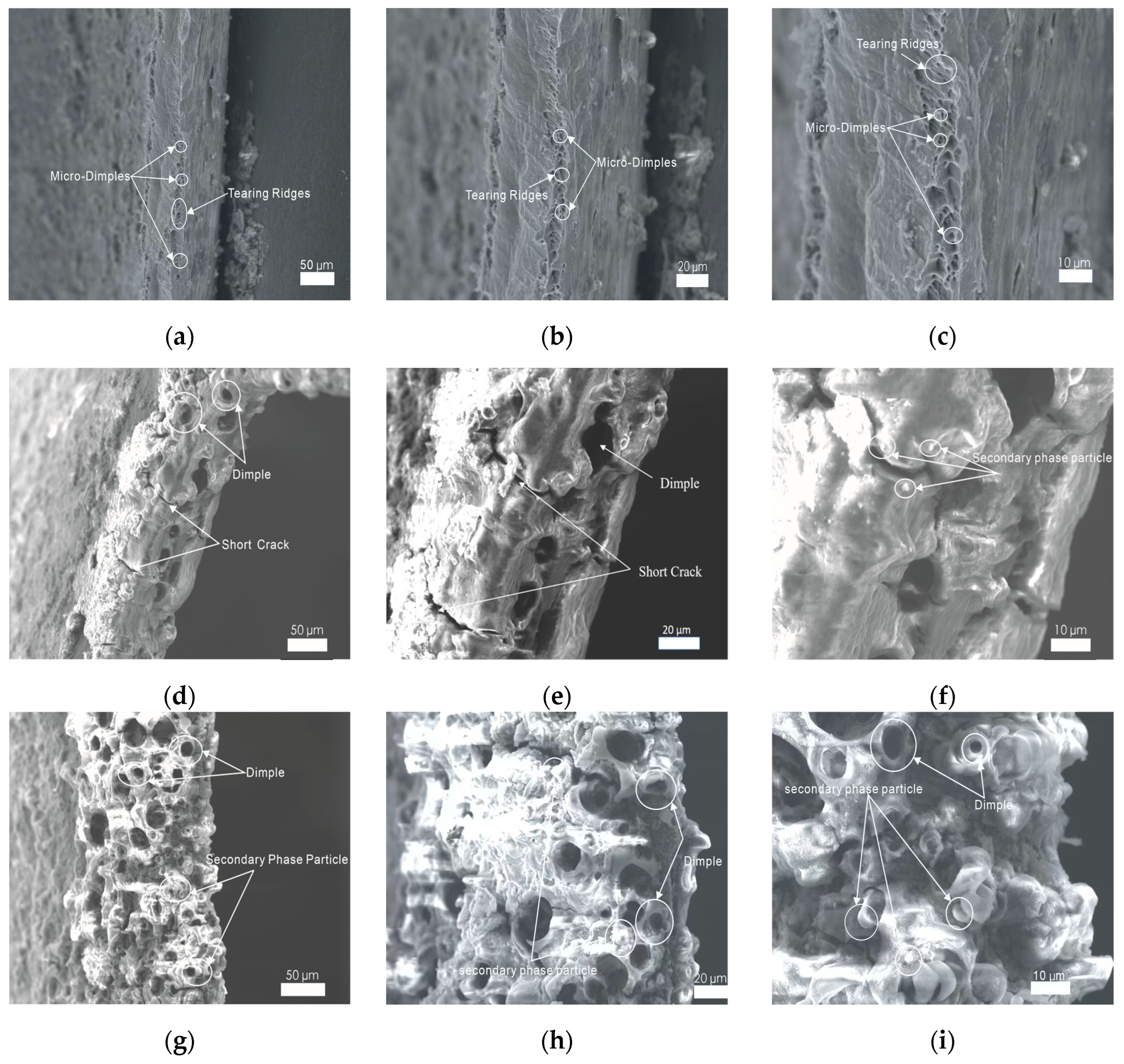

Table 1.
Chemical composition of 1060 aluminum alloy.
| Si | Fe | Cu | Mn | Mg | V | Zn | Ti | Al |
|---|---|---|---|---|---|---|---|---|
| 0.25 | 0.35 | 0.05 | 0.03 | 0.03 | 0.05 | 0.05 | 0.03 | ≥99.60 |
Table 2.
Measurement conditions for residual stress tests.
| Parameters | Sample for SPIF | Sample for LUVIF | Sample for 2D-UVIF |
|---|---|---|---|
| Pitch | 100μm | 100μm | 100μm |
| X-ray irradiation measure time | 90s | 90s | 90s |
| X-ray irradiation max time | 120s | 120s | 120s |
| X-ray tube current | 1.50mA | 1.50mA | 1.50mA |
| X-ray tube voltage | 30.00kV | 30.00kV | 30.00kV |
| Sample distance (Monitor) | 65.000mm | 65.000mm | 65.000mm |
| Sample distance (Analysis) | 63.908mm | 65.990mm | 66.174mm |
| X-ray incidence angle | 35.0° | 35.0° | 35.0° |
| Offset of alpha angle | 0° | 0° | 0° |
| X-ray wavelength (K-Alpha) | 2.29093[A](Cr) | 2.29093[A](Cr) | 2.29093[A](Cr) |
| X-ray wavelength (K-Beta) | 2.08480[A](Cr) | 2.08480[A](Cr) | 2.08480[A](Cr) |
| Total measurement count | 45376 | 45381 | 45386 |
| Oscillation count | 7 | 7 | 7 |
| Detection sensitivity | 53.4% | 39.6% | 56.5% |
| Peak strength | 317k | 144k | 211k |
| Level of ambient light | 0.3% | 0.3% | 0.3% |
| Temperature | 38.38℃ | 46.50℃ | 43.69℃ |
| Valid range of alpha angle | 18°-90° | 18°-90° | 18°-90° |
| Peak analysis method | Fitting Lorentz | Fitting Lorentz | Fitting Lorentz |
Disclaimer/Publisher’s Note: The statements, opinions and data contained in all publications are solely those of the individual author(s) and contributor(s) and not of MDPI and/or the editor(s). MDPI and/or the editor(s) disclaim responsibility for any injury to people or property resulting from any ideas, methods, instructions or products referred to in the content. |
© 2024 by the authors. Licensee MDPI, Basel, Switzerland. This article is an open access article distributed under the terms and conditions of the Creative Commons Attribution (CC BY) license (http://creativecommons.org/licenses/by/4.0/).
Copyright: This open access article is published under a Creative Commons CC BY 4.0 license, which permit the free download, distribution, and reuse, provided that the author and preprint are cited in any reuse.


