Submitted:
27 January 2024
Posted:
29 January 2024
You are already at the latest version
Abstract
In this research, a screw-barrel system was designed and implemented, coupled with material extrusion, to print high-melt-temperature thermoplastic materials. The aim was to integrate two methods: the direct extrusion of thermoplastic polymer pellets with material extrusion,utilize various polymers in the form of pellets, especially high melt temperature ones, instead of traditional filaments. This addresses one of the significant challenges in filament preparation for various materials that are not readily available in the market or nearly impossible to fabricate (such as highly filled plastics). First, the screw-barrel assembly performance and factors influencing feed rate were evaluated. Subsequently, specimens were printed with polyether ether ketone (PEEK), an advanced plastic material known for its outstanding mechanical properties, high-temperature tolerance, and broad applications in various sectors, such as medical. Additionally, the material was reinforced with 2.5% continuous glass fibers while printing, which presented a novel product. Upon comparing theoretical values with experimental data from the tensile testing, a notable observation emerged: the inclusion of 2.5% glass fibers led to an approximate 43% increase in the tensile strength of the material. Furthermore, SEM images provided visual evidence of satisfactory adhesion between layers and fibers.
Keywords:
Direct Extrusion of Materials
; Additive manufacturing
; Screw-barrel
; Polyether Ether Ketone (PEEK)
; Glass Fibers
1. Introduction
As additive manufacturing processes have grown vastly and attracted attentions and applications in various sectors, challenges have become apparent, including lower strength of produced items compared to traditional methods (such as machining for metal products and plastic injection for polymer products), relatively poor dimensional accuracy stemming from layer-by-layer effects, limited repeatability, and a lack of standards for these processes and especially material limitations [1,2,3].
Among various additive manufacturing methods, the fused deposition modeling (FDM) process, has gained popularity due to its cost-effectiveness and widespread applicability [4,5,6]. The primary raw material form utilized in this method is filament, often made from materials such as polylactic acid (PLA), acrylonitrile butadiene styrene (ABS), and others [7,8,9,10,11]. However, challenges arise due to the inherent properties of some materials, such as their brittleness and the difficulties in producing and collecting filaments easily [12,13].
Additive manufacturing, based on direct extrusion from pellets, can be used for various shaping processes, where molten materials exhibit complex rheological behavior with high content of solid inclusions. The properties of molten materials and the flow characteristics are key factors for quality shaping in layer-by-layer extrusion-based processes [14].
Polyether ether ketone (PEEK) is an advanced thermoplastic polymer known for its high melting temperature, chemical and abrasion resistance, and excellent mechanical properties, especially toughness [15]. Today, PEEK has diverse engineering applications. Its chemical and abrasion resistance in harsh environments, coupled with its ability to withstand thermal sterilization processes, make PEEK suitable for medical applications like orthopedic implants and spinal columns [16,17,18,19]. Given its importance and the high cost compared to other engineering polymers such as PMMA, POM, and PBT, direct use of PEEK pellets increases efficiency and reduces costs in final part production. However, due to the high melting temperature and viscosity, 3D printing of these materials based on direct extrusion poses significant challenges [20,21,22,23,24].
Karl Peter Davidson et al. designed and constructed a 3D printer with direct pellets extrusion capability. They optimized the process conditions using polystyrene, reporting the optimal parameters, including cylinder and print bed temperatures.
Drothman Dylan et al. directly extruded PLA pellets. Recognizing that the extruder’s output rate was insufficient for optimal printing, they made modifications to the assembly. By reducing the auger size, they increased the printing rate.
Volptao et al. examined polypropylene pellets using a cylinder-piston system, where the device features a fixed cylinder and a movable piston. The mechanical tests on the output strings resulted in a maximum tensile strength of 30 MPa with a scattering of 2.3 MPa and an elastic modulus of 2.1 GPa.
Jian-Wei Tseng et al. designed a 3D printer system with direct extrusion capability, allowing for high-quality printing of materials with high viscosity and melting temperature, such as PEEK. Using this method, they achieved a 96% retention of the mechanical properties of the target material. SEM and XRD results indicated that thermal conditions were the primary factor influencing mechanical strength.
Van der Klift et al. used a commercial 3D printer designed specifically to embed continuous nylon-based glass fibers. Two different volume percentages of glass fibers were used to test the samples’ tensile strength. In the first composition, 140 MPa and 14 GPa were obtained, respectively, and in the second composition, 464 MPa and 37.7 GPa were obtained.
Betini et al. utilized FDM to create 3D-printed composites reinforced with continuous fibers. An approximate 8.6% volumetric percentage of fibers was obtained. Compared to regular PLA, the printed samples demonstrated six times greater tensile strength and three times higher modulus.
The utilization of 3D printers based on direct extrusion methods promises widespread applications. In the current study, a screw-barrel extruder was designed, manufactured, and utilized for direct extrusion on an additive layer-building platform. Initially, polycarbonate (PC) pellets were used to examine the parameters affecting the rate of molten output. Then, the samples of PEEK from pellets and its composites reinforced simultaneously with glass fibers were printed for assessment of tensile strength.
2. Materials and Methods
2.1. Raw Materials:
Two main polymeric materials were used in the experimentations: a) polycarbonate (PC), as a candidate of engineering plastics, and b) polyether ether keton (PEEK) as a candidate from advanced plastics.
2.1.1. Polycarbonate 1100UV
The pellets of Polycarbonate-1100UV from Honam Company, South Korea, known for their thermal resistance, color stability, and flame retardancy was utilized with the engineering specifications presented in Table 1.
2.1.2. PEEK
PEEK 5600G from Juanha Co., China, was employed which possesses acceptable strength against abrasion and pressure and is used in industries such as; oil, gas and electrical engineering. The engineering specifications of these materials are presented in Table 2.
2.1.3. Glass Fiber Yarn
2.2. Direct Extrusion System for Pellets with Screw-Barrel Mechanism
For the purpose of direct extrusion of polymer pellets, a screw with a diameter of 15 mm and a length of 300 mm, with a pitch of 14 mm and three thermal zones: feeding, compression and metering, was designed and manufactured. Furthermore, a distinct barrel was machined with an outer diameter of 22 mm, an entrance of 15mm in diameter featuring the material feed section, and a connected hopper for seamless material transfer to establish a continuous material flow from a copper warehouse. This design also includes a 45-degree angle orifice for the entry of glass fibers and an M6 hole for nozzle connection. Overall, the effort reflected a meticulous design and construction process. Heat was transferred to the barrel and screw housing using three band heaters, each with a power of 130W, and controlled separately via three thermocouples connected to the cylinder. Furthermore, a separate unit from the material extrusion platform was used as the temperature control unit for the direct extruder system. A heat sink and a fan as a cooling unit were also used at the material entrance section to prevent pellets from pre-mature melting and clogging the entrance. (see Figure 1)
2.3. Additive Manufacturing Platform
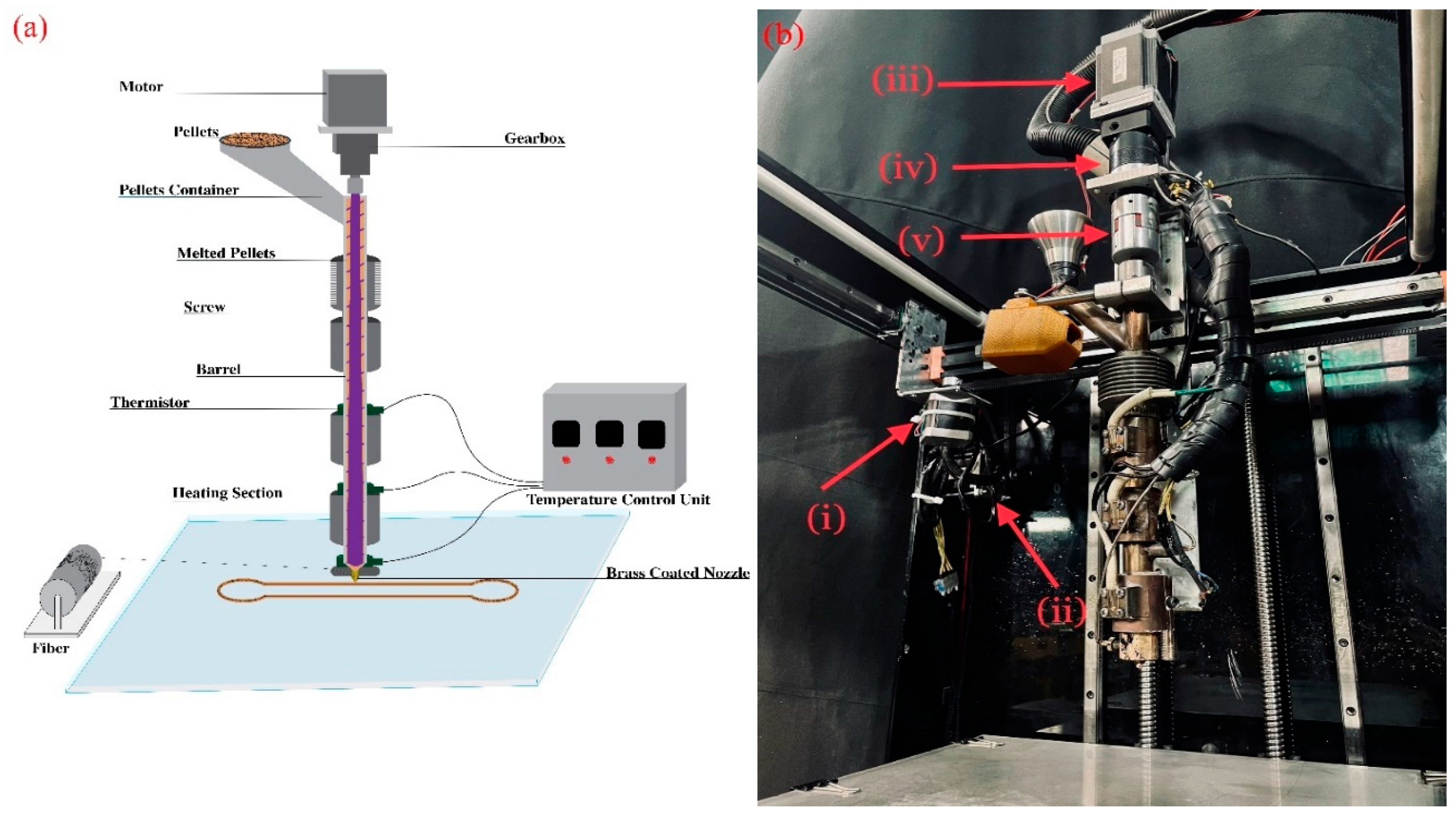
In this research, a material extrusion platform was employed with a linear guide and box system in the X and Y axis, a NEMA17 stepper motor for the Y axis, a Leadshine 57CM13 motor with control driver DM566 for the X axis and two NEMA13 stepper motors for Z-Axis. Additionally, for controlling the rotation of the screw, a 57CM26 motor, a control driver Leadshine DM566, and a Sesame-PBE gearbox with a 1:5 ratio connected to a flexible coupling were used for precise control of the molten flow rate. The components of the melt extrusion platform were controlled by Makerbase board. Figure 4 illustrates the melt extrusion platform based on direct pellets extrusion.
Figure 2.
(a) Schematic of screw extrusion-based additive manufacturing (b) material extrusion platform based on direct pellet extrusion (i) Y-axis motors (ii) X-axis motor (iii) extruder motor (iv) gearbox (v) flexible coupling.
Figure 2.
(a) Schematic of screw extrusion-based additive manufacturing (b) material extrusion platform based on direct pellet extrusion (i) Y-axis motors (ii) X-axis motor (iii) extruder motor (iv) gearbox (v) flexible coupling.
2.4. Mechanical Properties
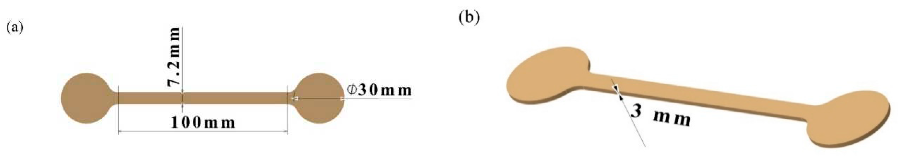
The tensile properties of the printed materials using the 3D printer based on the direct extruder system were evaluated using a universal testing machine (SANTAM STM-20, Santam Co., Iran). The load capacity of the selected force sensors for the printed materials was 20 kN. The extension rate for the specimens was set at 5 mm/min. The specimens were printed in a rectangular shape with dimensions of 100×7.2×3 mm, featuring four layers specifically designed for the tensile test. As depicted in Figure 3, two half circles with a diameter of 30 mm were added at both ends of the sample in order to improve print quality and maintain fiber integrity. At least three specimens were tested to ensure reliable data, and the results were reported as the average of the obtained data. The load was applied parallel to the deposited raster to assess the maximum effect of continuous fiber on the tensile properties.
Figure 3.
Geometric specifications of the printed specimen for tensile test (a) top view (b) isometric view
Figure 3.
Geometric specifications of the printed specimen for tensile test (a) top view (b) isometric view
2.4.1. Fiber Volumetric Percentage
The volumetric percentage of glass fibers in the printed composite specimens was calculated using the geometric specifications of the printed specimens, assuming no change in the cross-sectional area of the fibers after deposition, determined by Figure 4 and Equation 1 [32,33].
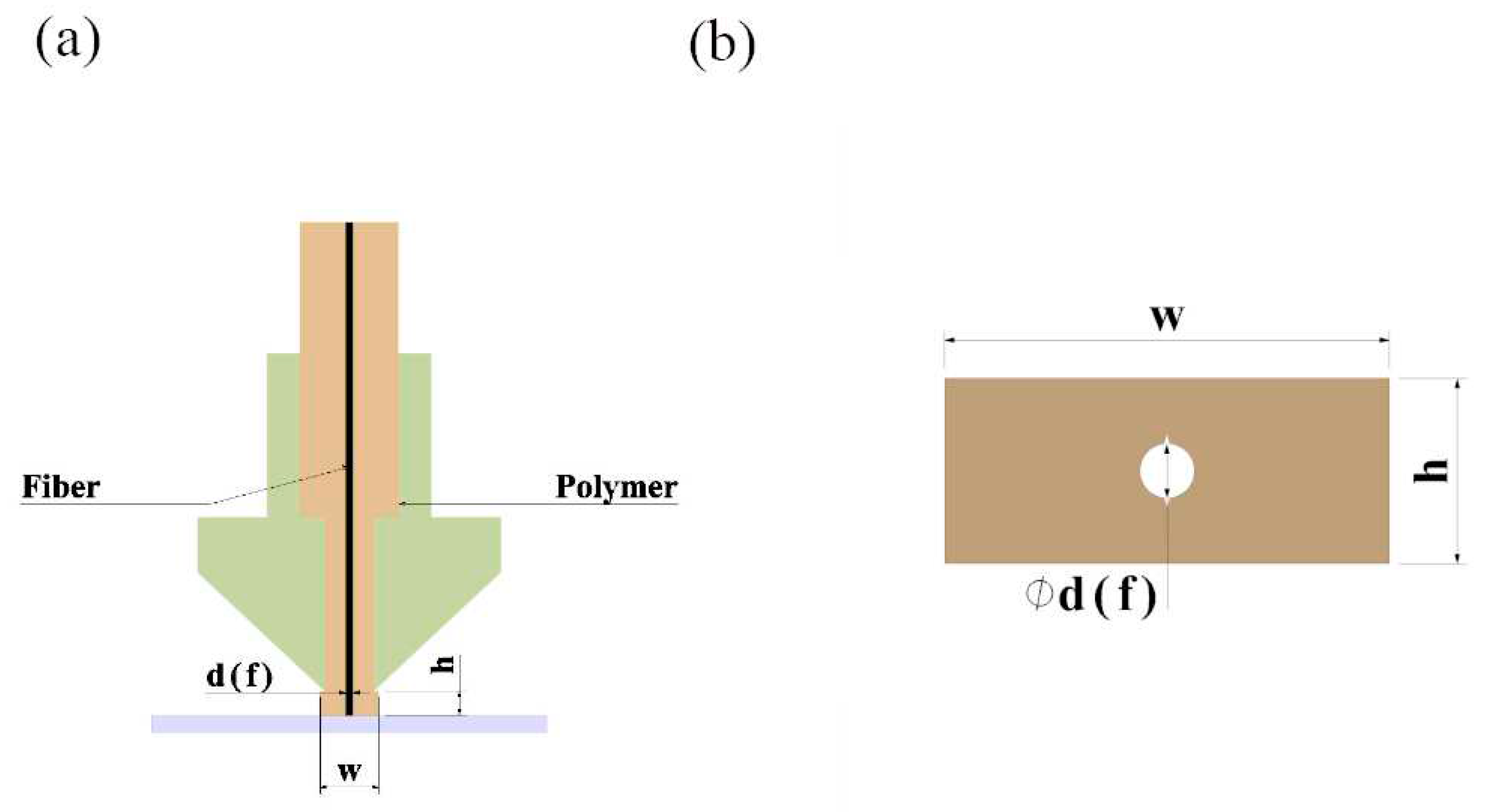 where represents the diameter of the glass fiber, and W and h denote the width and thickness of the layer, respectively.
Figure 4.
Cross-sectional view of (a) the nozzle presenting the fiber embedded in the polymeric melt (b) the approximate geometry of cross section of the printed specimen with glass fiber.
Figure 4.
Cross-sectional view of (a) the nozzle presenting the fiber embedded in the polymeric melt (b) the approximate geometry of cross section of the printed specimen with glass fiber.
2.5. Microscopy Evaluation
In order to examine the overall structure of the printed specimens by the direct extrusion-based 3D printer, an Insize 250X optical microscope was used.
To investigate the structure of the printed specimens, evaluate the adhesion between the polymer matrix and glass fibers, and examine the fracture surfaces following tensile testing, a Scanning Electron Microscope (SEM, Tescan VEGA-II) was employed.
2.6. Statistical Analysis Method
The Taguchi method and L9 array were used to conduct an experiment in order to investigate the effect of selected variables, such as the speed of the extruder, the average temperature, and the diameter of the nozzle on the output flow rate of molten material. Table 4 illustrate the experimental designs based on the Taguchi method.
3. Result and Discussion
3.1. The Effect of Pivotal Parameters on the Molten Flow Rate
In order to determine if the extruder speed, nozzle diameter, and temperature affect the molten flow rate, a polycarbonate material with a high viscosity was extruded at a specified temperature and speed for 150 seconds. The mass of the extruded material was measured using precision scales with an accuracy of 0.01 grams. The extruded flow rate for each experiment was then calculated. Table 5 represents the measured flow rates.
According to the plots in Figure 5, the effect of selected parameters on the material flow rate indicates that the extruder speed is the most influential factor on the material flow rate; as the extruder speed increases, the flow rate will also increase. The other two parameters had a slight, close to negligible effect on the flow rate, in the range of examined parameters.
3.2. Mechanical properties
To investigate the tensile properties, specimens, tensile test specimens of both PEEK material without fibers and glass fiber-reinforced composites were successfully printed, according to the geometry presented in Figure 3. A comprehensive examination of the tensile strength of raw materials and glass fiber composites was performed by laying the specimens flat along the direction of tensile force (0°), as shown in Figure 6. Furthermore, the printing conditions for the specimens are provided in Table 6.
3.3. Theoretical estimation of tensile strength
The volumetric percentage of glass fibers in the printed composite specimens was calculated using Table 6, Figure 2 and Equation 1. A value of 2.5% for the glass fiber content is obtained by applying Equation 1. To achieve theoretical values for tensile strength and Young’s modulus, Equations 2 and 3 are used based on the rule of mixtures (ROM) [34].
Where represent the tensile strength and Young’s modulus values for the polymeric material and fiber, respectively. Considering these values, the theoretical tensile strength and Young’s modulus of reinforced composite are calculated as 121 MPa and 5.1 GPa, respectively, according to Equations 3 and 4. Figure 7 illustrates a printed composite sample with 2.5% glass fiber content under tensile testing.
Figure 8 represents the stress-strain curve obtained in this experiment. Based on experimental data, tensile strength and Young’s modulus of the PEEK composite were calculated. The obtained values of tensile strength and modulus of elasticity for each of the specimens are presented in Table 7. Figure 9 shows images captured by an optical microscope, illustrating the printed material along with glass fibers, fractured sections and voids during printing The results indicate a significant improvement in mechanical properties, including tensile strength and Young’s modulus, when embedding glass fibers, by about 43% and 34%, respectively, by adding only 2.5% of fiber content.
According to the result, printed specimens without fibers have average tensile strength and Young’s modulus values of 81 MPa and 3.1 GPa, respectively. These values exhibit differences of 19% in Tensile strength and 19% in Young’s modulus compared to the materials datasheet presented in Table 2, which are 100 MPa and 3.8 GPa, respectively. Additionally, considering the values obtained from Table 7 and the theoretical tensile strength and Young’s modulus values obtained from Equations 2 and 3, and comparing these two sets of values, the results from the printed specimens show a difference of 5% in tensile strength and 17% in Young’s modulus compared to the theoretical values. Figure 10 provides comparisons of the tensile strength and Young’s modulus results obtained from the specimens without fibers, fiber-reinforced composites, and their theoretical values. The presence of morphological defects during printing, material shrinkage upon exiting the nozzle, and the adhesion quality between glass fibers and printed materials, observable in Figure 11 and Figure 9 could explain the differences between theoretical and experimental values.
4. Conclusion
In this experimental research, a direct-feed extrusion system was designed, fabricated, and implemented on a material extrusion platform to feed polymeric pellets (or powders) directly instead of prefabricated filaments. The purpose was to utilize various polymeric materials and their composition, where their filament forms are not readily available or hard to fabricate. The study initially focused on examining the variables affecting the material extrusion rate in the direct pellets extrusion system for high-viscosity polycarbonate pellets. Factors such as extruder speed, barrel temperature, and nozzle diameter were investigated, revealing that an increase in extruder speed was the most influencing parameter compared to the nozzle diameter and temperature in the examined ranges. Furthermore, PEEK pellets were fed to print neat and reinforced specimens with 2.5% glass fibers. Tensile strength and Young’s modulus were measured from tensile tests and compared with the calculated theoretical values using the rule of mixtures. The Tensile strength of the printed samples without fibers was 80 81 MPa, showing a 19% difference, and the Young’s modulus was 3 GPa, with a 19% difference compared to the material datasheet, which are 100 MPa and 3.8 GPa, respectively. Additionally, the tensile strength and Young’s modulus of the printed specimens with the glass fiber composite were 115 MPa and 4.2 GPa, respectively. These values indicated a difference of 5% and 17%, respectively, compared to theoretical values, which were 121 MPa and 5.1 GPa. These variations in tensile strength and Young’s modulus can be attributed to some existing morphological defects during printing, material shrinkage upon exiting the nozzle, and imperfect adhesion between glass fibers and printed materials.
Author Contributions
Hadi Amirahmadi: Conceptualization, Methodology, Software, Funding acquisition, Writing-Original draft preparation, Resources. Amir Hossein Behravesh: Supervision, Project administration, Writing-Review & Edition, Data curation, Validation, Conceptualization. Ali Amirahmadi: Software, Formal analysis, Investigation, Writing-Original draft. Iman Ghaderi: Writing-Review & Editing, Software, Validation. Seyyed Kaveh Hedayati: Validation. Ahmadreza Tahmasebi: Visualization. Amir Bakhtiary: Validation.
Funding
The author(s) received no financial support for the research, authorship, and/or publication of this article.
Conflicts of Interest
The authors declare that they have no known competing financial interests or personal relationships that could have appeared to influence the work reported in this paper.
References
- Mori, K.-i., T. Maeno, and Y. Nakagawa, Dieless forming of carbon fiber reinforced plastic parts using 3D printer. Procedia engineering, 2014. 81: p. 1595-1600.
- Guo, N. and M.C. Leu, Additive manufacturing: technology, applications and research needs. Frontiers of Mechanical Engineering, 2013. 8 (3) p. 215-243.
- Kumar, S., Kruth, J.-P., 2010. Composites by rapid prototyping technology. Materials & Design, 31 (2), 850-856. [CrossRef]
- Goyanes A, Buanz AB, Basit AW, et al. Fused-filament 3D printing (3DP) for fabrication of tablets. Int J Pharm 2014; 476: 88–92. [CrossRef]
- Hopkinson, E.N., E.R. Hague, and E. Dickens, Rapid manufacturing: An industrial revolution for the digital age. 2006: John Wiley & Sons.
- Tim A. Osswald, John Puentes, Julian Kattinger, Fused filament fabrication melting model, Additive Manufacturing, Volume 22, 2018, Pages 51-59, ISSN 2214-8604. [CrossRef]
- N. Kumar, S. Shaikh, P.K. Jain, P. Tandon, Effect of fractal curve-based toolpath on part strength in fused deposition modelling, Int. J. Rapid Manuf. 5 (2015) 186. [CrossRef]
- D. Zhao, W. Guo, Shape and Performance Controlled Advanced Design for Additive Manufacturing: A Review of Slicing and Path Planning, Journal of Manufacturing Science and Engineering, Transactions of the ASME 142 (2020). [CrossRef]
- M. Taufik, P.K. Jain, Estimation and simulation of Shape deviation for Additive Manufacturing prototypes, Proc. ASME Des. Eng. Tech. Conf. 4 (2016) 1–10.
- Calhoun, A., and Peacock, A., Polymer Chemistry – Properties and Applications, Hanser Publishers, Munich (2006).
- Amy M. Peterson, Review of acrylonitrile butadiene styrene in fused filament fabrication: A plastics engineering-focused perspective, Additive Manufacturing, Volume 27, 2019, P 363-371. [CrossRef]
- Jamison Go, Scott N. Schiffres, Adam G. Stevens, A. John Hart, Rate limits of additive manufacturing by fused filament fabrication and guidelines for high-throughput system design, Additive Manufacturing, Volume 16, 2017, Pages 1-11, ISSN 2214-8604. [CrossRef]
- Parulski, C., Jennotte, O., Lechanteur, A., & Evrard, B. (2021). Challenges of fused deposition modeling 3D printing in pharmaceutical applications: Where are we now? Advanced Drug Delivery Reviews, 175 113810.
- L.G. Blok, M.L. Longana, H. Yu, B.K.S. Woods, an investigation into 3D printing of fibre reinforced thermoplastic composites, Addit. Manuf. 22 (2018) 176– 186. [CrossRef]
- Nayak, P.K. Jain, P.K. Kankar, Progress and issues related to designing and 3D printing of endodontic guide, in: Lect. Notes Mech. Eng., Pleiades Publishing, 2019: pp. 331–337.
- Jones, D.P., Leach, D.C., Moore, D.R., 1985. Mechanical properties of poly (ether-ether ketone) for engineering applications. Polymer 26 (9), 1385–1393.
- Nguyen, H.X., Ishida, H., 1987. Poly(aryl-ether-ether-ketone) and its advanced composites: a review. Polymer Composites 8 (2), 57–73.
- Kurtz, S.M., Devine, J.N., 2007. PEEK biomaterials in trauma, orthopedic, and spinal. [CrossRef]
- implants. Biomaterials 28 (32), 4845–4869.
- Haoze Wang, Peng Chen, Hongzhi Wu, Annan Chen, Siqi Wu, Jin Su, Mingzhe Wang, Xiaobo Feng, Cao Yang, Lei Yang, Chunze Yan, Yusheng Shi,Comparative evaluation of printability and compression properties of poly-ether-ether-ketone triply periodic minimal surface scaffolds fabricated by laser powder bed fusion, Additive Manufacturing, Volume 57,2022,102961. [CrossRef]
- Wang, Y.; Muller, W.D.; Rumjahn, A.; Schmidt, F.; Schwitalla, A.D. Mechanical properties of fused filament fabricated peek forbiomedical applications depending on additivemanufacturing parameters. J. Mech. Behav. Biomed. Mater. 2020, 115, 104250. [Google Scholar]
- Wang, P.; Zou, B.; Ding, S.; Li, L.; Huang, C. Effects of fdm-3d printing parameters on mechanical properties and microstructure of cf/peek and gf/peek. Chin. J. Aeronaut. 2020, 34. [Google Scholar] [CrossRef]
- Toth J, Wang M, Estes B, Scifert J, Seim H, Turner A: Polyetheretherketone as a biomaterial for spinal applications. Biomaterials 2006; 27:324–34.
- Pokorny D, Fulin P, Slouf M, Jahoda D, Landor I, Sosna A. Polyetheretherketone (PEEK). Part II: Application in clinical practice. Acta Chir Orthop Traumatol Cech 2010; 77:470–8.
- Arit Das, Camden A. Chatham, Jacob J. Fallon, Callie E. Zawaski, Eric L. Gilmer, Christopher B. Williams, Michael J. Bortner, Current understanding and challenges in high temperature additive manufacturing of engineering thermoplastic polymers, Additive Manufacturing, Volume 34, 2020,101218. [CrossRef]
- Singamneni, Sarat & Huang, Bin & Davidson, Karl. (2012). Polystyrene in Granular Form for Fused Deposition Modeling. ASME/ISCIE 2012 International Symposium on Flexible Automation, ISFA 2012. [CrossRef]
- Drotman, D. T, Design of a Screw Extruder for Additive Manufacturing. 2015, UC San Diego.
- Volpato, N., Kretschek, D., Foggiatto, J.A. et al. Experimental analysis of an extrusion system for additive manufacturing based on polymer pellets. Int J Adv Manuf Technol 81, 1519–1531 (2015). [CrossRef]
- Tseng, J. W., Liu, C. Y., Yen, Y. K., Belkner, J., Bremicker, T., Liu, B. H., Sun, T. J., & Wang, A. B. (2018). Screw extrusion-based additive manufacturing of PEEK. Materials and Design, 140, 209-221. [CrossRef]
- Van Der Klift F, Koga Y, Todoroki A, et al. 3D printing of continuous carbon fibre reinforced thermo-plastic (CFRTP) tensile test specimens. OJCM 2015; 6: 18.
- Bettini P, Alitta G, Sala G, et al. Fused deposition technique for continuous fiber reinforced thermoplastic.J Mater Eng Perform 2017; 26: 843–848. [CrossRef]
- Akhoundi B, Behravesh AH and Bagheri Saed A. Improving mechanical properties of continuous fiber-reinforced thermoplastic composites produced by FDM 3D printer. J Reinf Plast Compos 2019; 38: 99–116. [CrossRef]
- Akhoundi, B., A.H. Behravesh, and A.J.P.o.t.I.o.M.E. Bagheri Saed, Part B: Journal of Engineering Manufacture, An innovative design approach in three-dimensional printing of continuous fiber–reinforced thermoplastic composites via fused deposition modeling process: in-melt simultaneous impregnation. 2020. 234(1-2): p. 243-259. [CrossRef]
- Hedayati, S.K., et al., 3D printed PCL scaffold reinforced with continuous biodegradable fiber yarn: A study on mechanical and cell viability properties. 2020. 83: p. 106347. [CrossRef]
- Kaw AK. Mechanics of composite materials. Boca Raton, FL: CRC press, 2005.
Figure 1.
Screw-barrel assembly designed and manufactured with three thermal zones: (i) feeding, (ii) compression, (iii) metering.
Figure 1.
Screw-barrel assembly designed and manufactured with three thermal zones: (i) feeding, (ii) compression, (iii) metering.
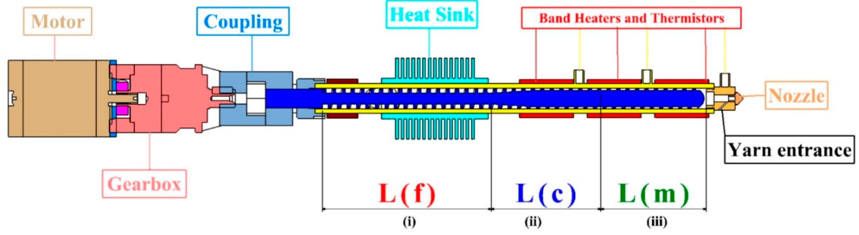
Figure 5.
Plots of the effect of temperature, nozzle diameter, and extruder speed on the extruder flow rate with a 14 mm pitch.
Figure 5.
Plots of the effect of temperature, nozzle diameter, and extruder speed on the extruder flow rate with a 14 mm pitch.
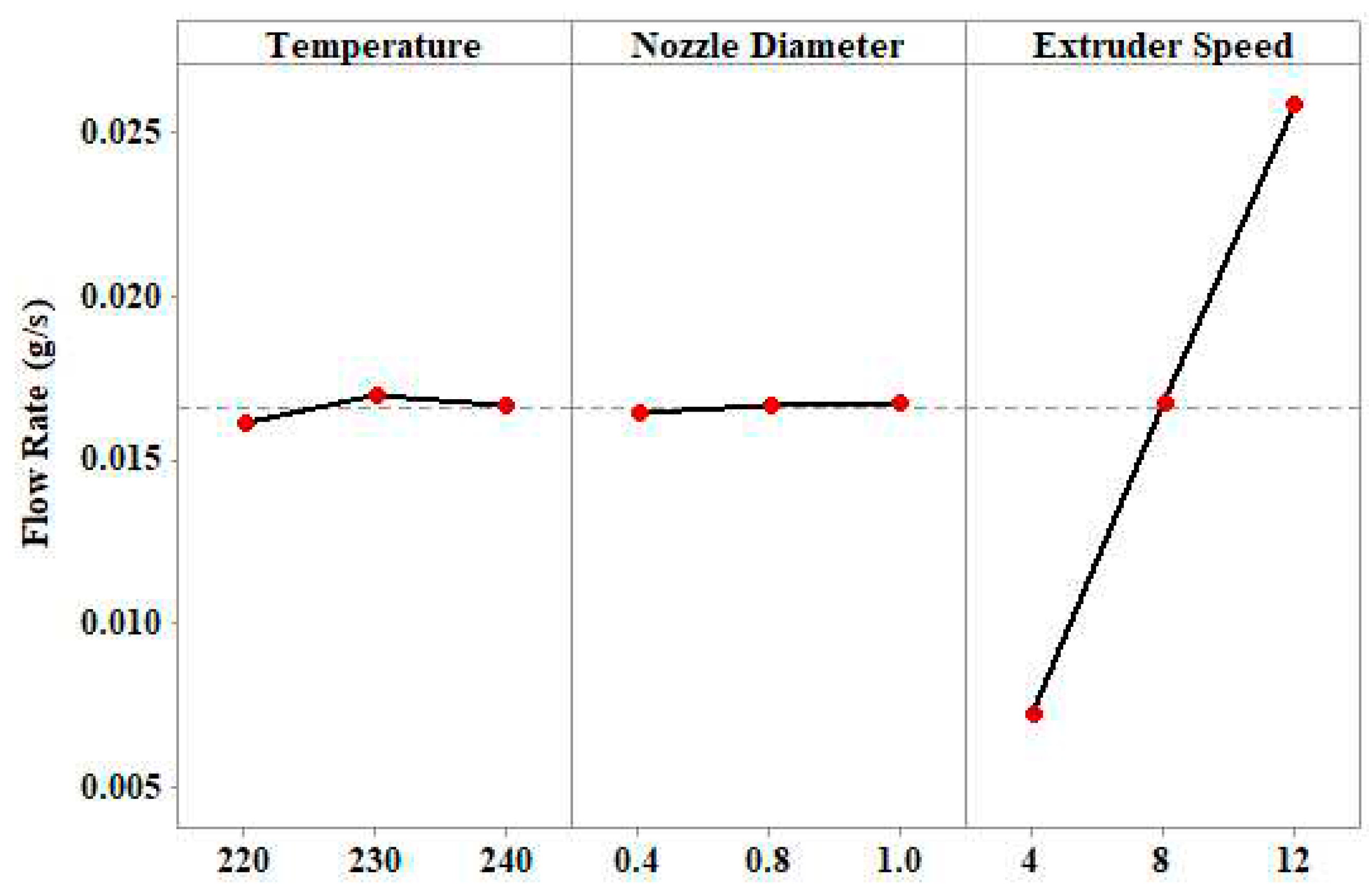
Figure 6.
–(a) Deposited raster with 0° angle with feeding yarn to the reservoir (b) printed PEEK specimens (i) with glass fibers (ii) without glass fibers.
Figure 6.
–(a) Deposited raster with 0° angle with feeding yarn to the reservoir (b) printed PEEK specimens (i) with glass fibers (ii) without glass fibers.
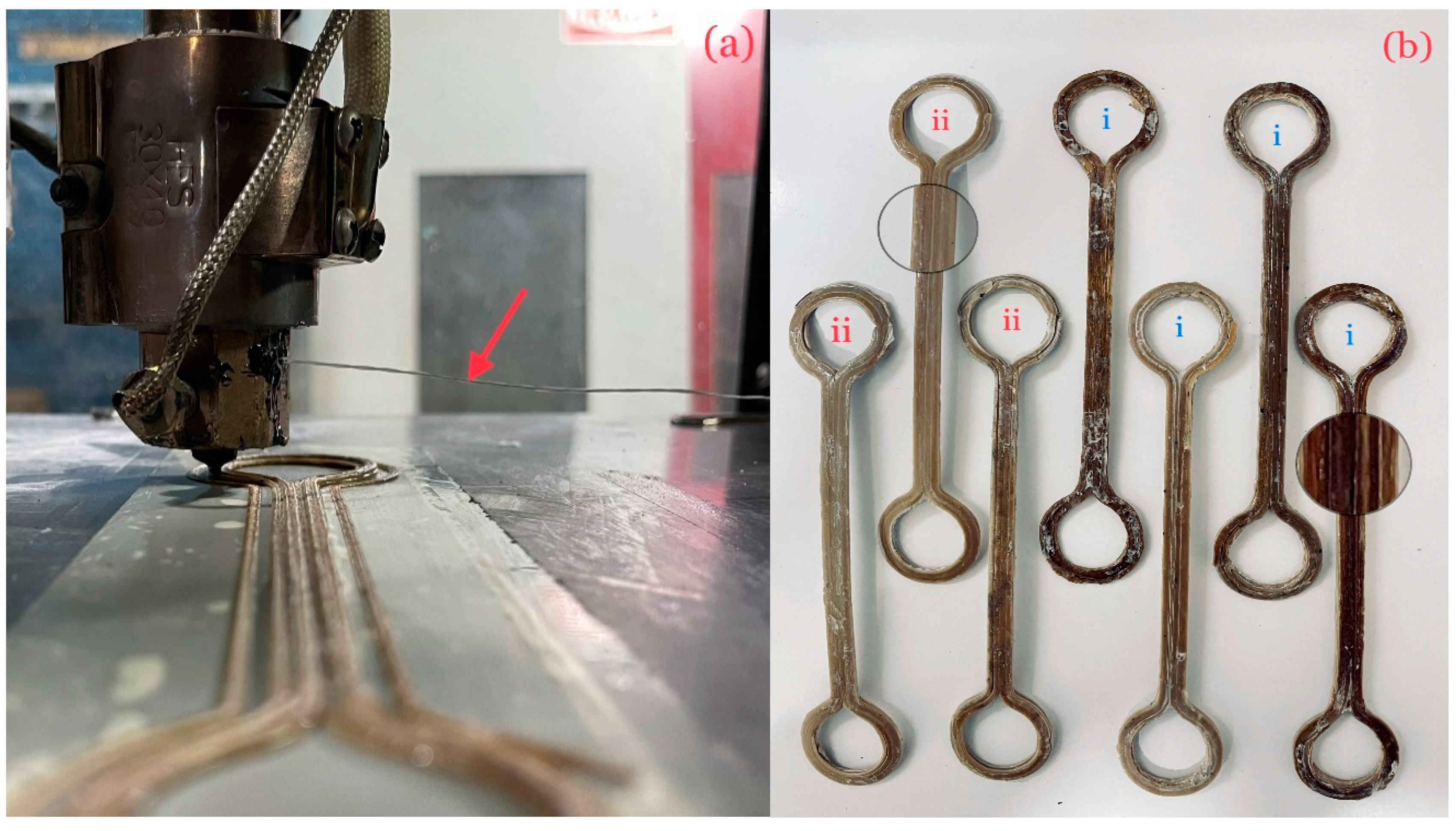
Figure 7.
(a) Tensile testing of a PEEK composite reinforced with continuous fibers (b) the specimen after fracture, where indicates the breakage of glass fiber yarn.
Figure 7.
(a) Tensile testing of a PEEK composite reinforced with continuous fibers (b) the specimen after fracture, where indicates the breakage of glass fiber yarn.

Figure 8.
Stress-Strain Diagram of printed PEEK specimens with 2.5% GF and Neat.
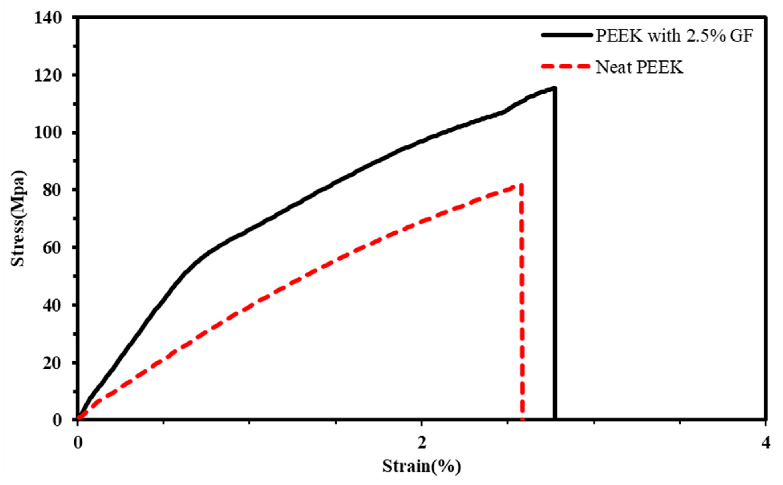
Figure 9.
Images captured by optical microscope (a) composite specimens reinforced with 2.5% glass fibers, (b) fractured area of the composite specimen with 2.5% glass fibers, (c) printed neat specimen, (d) fractured area of the printed neat specimens.
Figure 9.
Images captured by optical microscope (a) composite specimens reinforced with 2.5% glass fibers, (b) fractured area of the composite specimen with 2.5% glass fibers, (c) printed neat specimen, (d) fractured area of the printed neat specimens.
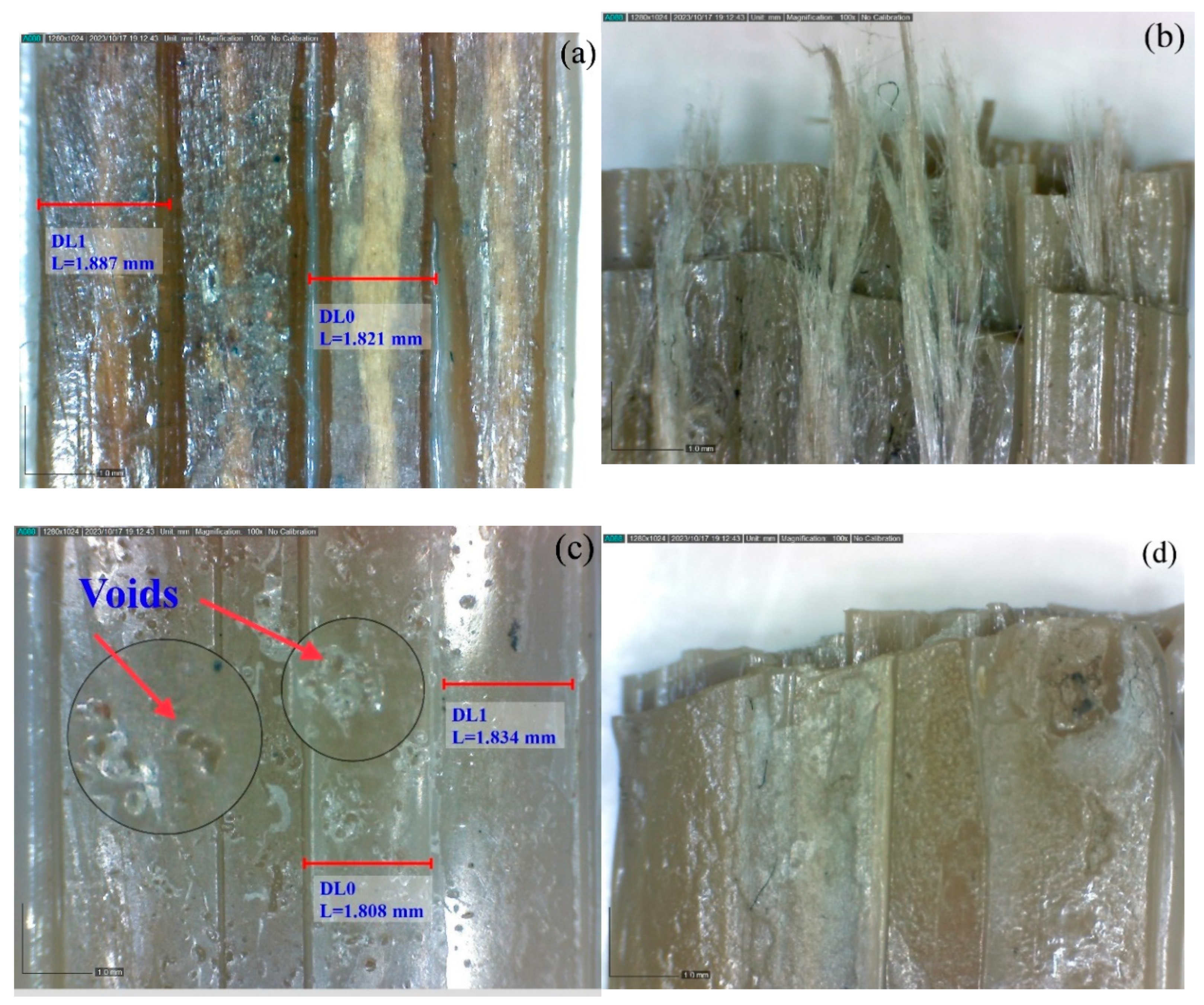
Figure 10.
Comparisons of the results from experiments and theoretical formulation: (a) tensile
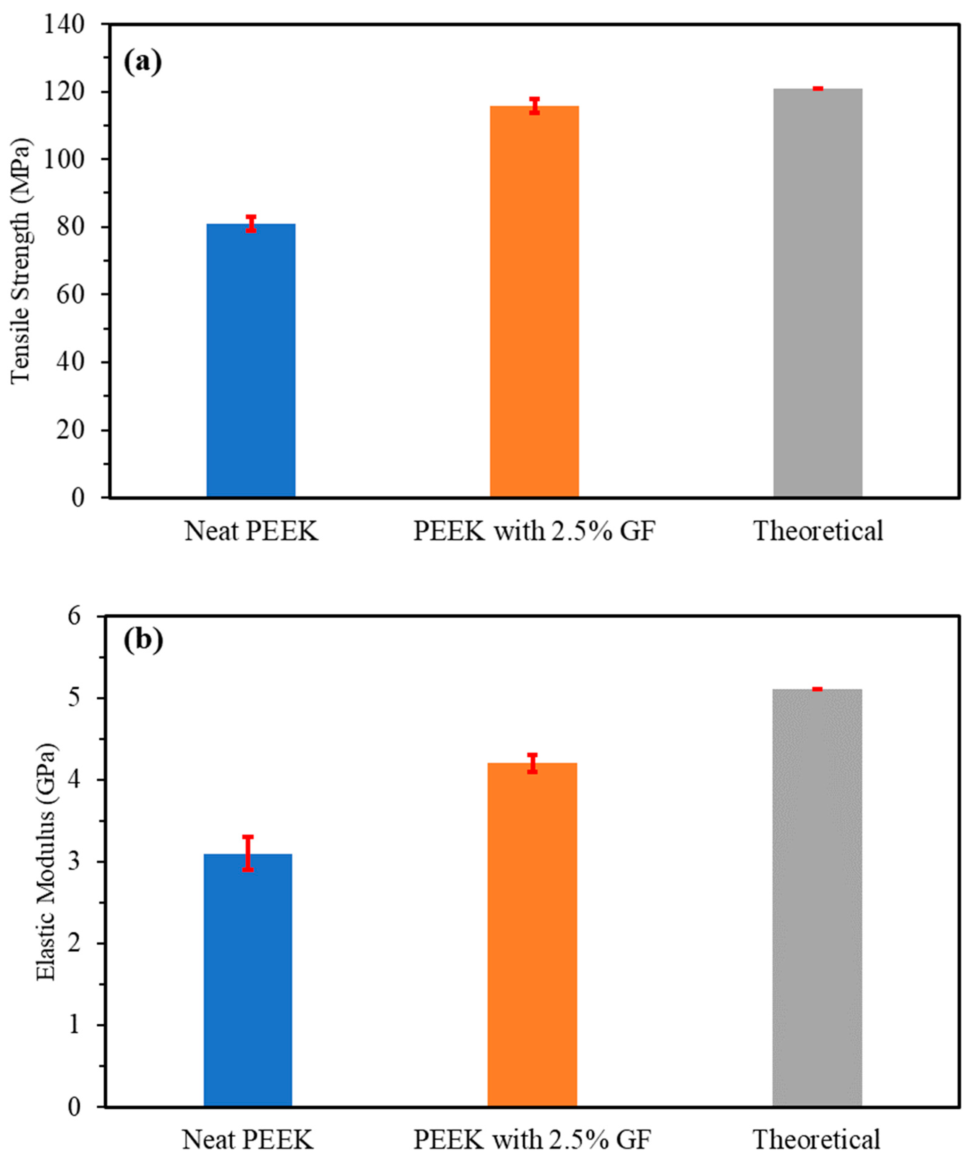
Figure 11.
SEM images of the fractured cross-section after tensile tests of the specimens (a,b) reinforced composite PEEK with 2.5 % GF (c,d) Neat PEEK strength, and (b) Young’s modulus.
Figure 11.
SEM images of the fractured cross-section after tensile tests of the specimens (a,b) reinforced composite PEEK with 2.5 % GF (c,d) Neat PEEK strength, and (b) Young’s modulus.
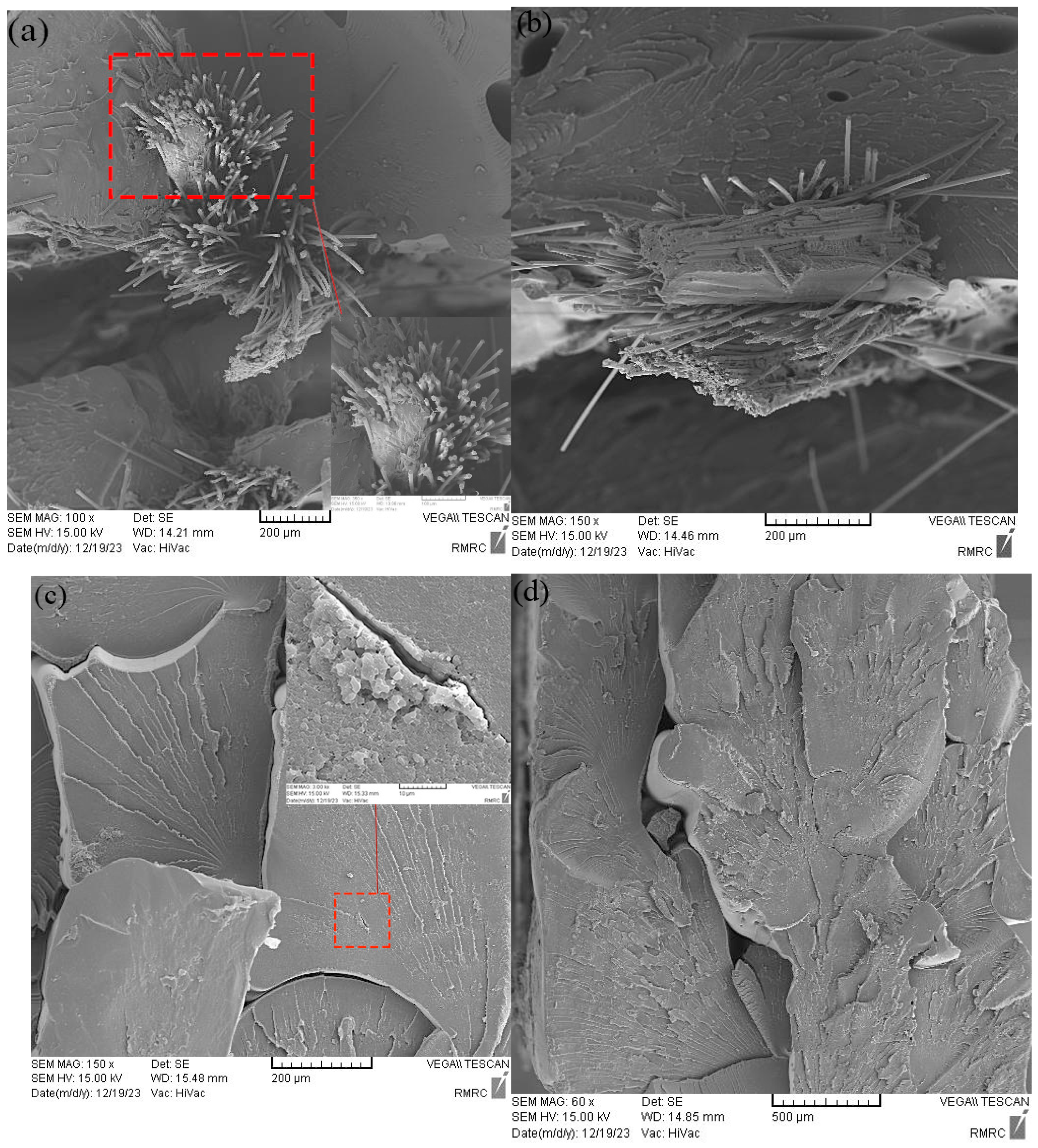

Table 1.
Technical specifications of polycarbonate PC-1100UV pellets.
| Property | Standard | Value | Unit |
|---|---|---|---|
| Physical | |||
| Melt Flow Rate | D1238 | 10 | |
| Density | D792 | 1.2 | |
| Mechanical | |||
| Tensile Modulus | D638 | 2.3 | GPa |
| Tensile Strength | D638 | 60 | MPa |
| Elongation at Break | D790 | 90 | % |
| Thermal | |||
| Softening Temperature | D1525 | 150 | °C |
| Heat Deflection Temperature | D256 | 60 | °C |
Table 2.
Technical specifications of PEEK 5600G pellets.
| Property | Standard | Value | Unit |
|---|---|---|---|
| Physical | |||
| Melt Flow Rate (400°C/2.16kg) | ISO 1133 | 18 | |
| Density | ISO 1183 | 1.3 | |
| Mechanical | |||
| Tensile Modulus | ISO 527 | 3.8 | MPa |
| Tensile Strength | ISO 527 | 100 | MPa |
| Elongation at Break | ISO 527 | 20 | % |
| Thermal | |||
| Melting Temperature | ISO 11357 | 343 | °C |
| Heat Deflection Temperature | ISO 75-1/-2 | 155 | °C |
Table 3.
Physical and mechanical specifications of fiberglass yarn.
| Physical Specifications | Value | Mechanical Properties | Value |
|---|---|---|---|
| Linear Mass | 0.1 | Maximum force | 36.24 N |
| Density | 2.5 | Tensile strength | 935 MPa |
| Fiber yarn diameter | 0.22 mm | Tensile modulus | 56.67 GPa |
| Cross-section area of fiber yarn | 0.03876 mm2 | Failure strain | 1.65% |
Table 4.
Taguchi L9 experimental design table for the extruder with a 14mm pitch.
| Experiment No | Barrel Temperature (°C) | Nozzle Diameter (mm) | Screw Speed (RPM) |
|---|---|---|---|
| 1 | 210 | 0.4 | 4 |
| 2 | 210 | 0.8 | 6 |
| 3 | 210 | 1 | 8 |
| 4 | 220 | 0.4 | 6 |
| 5 | 220 | 0.8 | 8 |
| 6 | 220 | 1 | 4 |
| 7 | 230 | 0.4 | 8 |
| 8 | 230 | 0.8 | 4 |
| 9 | 230 | 1 | 6 |
Table 5.
Measured extruded flow rates.
| Exp No | 1 | 2 | 3 | 4 | 5 | 6 | 7 | 8 | 9 |
|---|---|---|---|---|---|---|---|---|---|
| (mg/s) | 21±3 | 25±3 | 12±2 | 22±4 | 25±3 | 13±1 | 27±5 | 12±1 | 21±3 |
Table 6.
Printing conditions for tensile test specimens.
| Parameters | Values |
|---|---|
| Printing temperature in respective temperature zones | 310, 380, and 400 (°C) |
| Extrusion multiplier | 1 |
| Axis movement speed | 2 mm/s |
| Nozzle diameter | 1.5mm |
| Layer height | 0.75 mm |
| Extruded layer width | 1.8mm |
| Bed temperature | 120 (°C) |
Table 7.
Reported tensile strength values for 3d-printed specimens.
| Specimen type | Tensile Strength (MPa) | Young’s Modulus (GPa) |
|---|---|---|
| PEEK with 2.5% GF | 115±1 | 4.2±0.1 |
| Neat PEEK | 81±1 | 3.1±0.1 |
Disclaimer/Publisher’s Note: The statements, opinions and data contained in all publications are solely those of the individual author(s) and contributor(s) and not of MDPI and/or the editor(s). MDPI and/or the editor(s) disclaim responsibility for any injury to people or property resulting from any ideas, methods, instructions or products referred to in the content. |
© 2024 by the authors. Licensee MDPI, Basel, Switzerland. This article is an open access article distributed under the terms and conditions of the Creative Commons Attribution (CC BY) license (http://creativecommons.org/licenses/by/4.0/).
Copyright: This open access article is published under a Creative Commons CC BY 4.0 license, which permit the free download, distribution, and reuse, provided that the author and preprint are cited in any reuse.


