

Submitted:
23 January 2024
Posted:
24 January 2024
You are already at the latest version
Abstract
To study the coupling mechanism and dynamic response of the end-face movable gear trans-mission system under complex excitation, a specific configuration of end-meshing movable gear reduction mechanism was used to achieve predetermined rigid thrust transmission and mis-matched gear meshing functions, which solved the inherent defects of traditional harmonic gear mechanism thin-wall flexible wheel easy to be damaged by fatigue. Considering the phenomenon of elastic deformation of live teeth accompanied by significant changes in meshing characteristics in the transmission process of end-meshing harmonic reducer, the influence of dynamic meshing parameters, live tooth deformation, time-varying stiffness of tooth meshing, and time-varying backlash on nonlinear dynamic performance was explored, as well as the mechanism of mul-ti-parameter coupling on transmission performance. The nonlinear dynamics model of the end-meshing harmonic reducer is established to solve the chattering prediction problem. Finally, a comprehensive test bed for the transmission system of harmonic reducer with meshing type with adjustable characteristic end was built to verify the correctness of the theoretical model and provide the theoretical and technical basis for exploring the optimal parameter selection of pas-sive vibration suppression problem.
Keywords:
end meshing
; harmonic gear
; time-varying stiffness
; nonlinear dynamics
1. Introduction
The utilization of industrial robots and aerospace exploration activities, among other sectors, necessitates the critical joint systems of their institutions to comply with the significant reliability and bearing capacity requirements of harmonic gear transmission devices [1]. To mitigate the inherent shortcomings of flexspline within traditional harmonic reducers, which are susceptible to fatigue damage, and to guarantee the precise operational state of the transmission system, the end-face engagement is employed to effectuate predetermined rigid thrust transmission. This solution effectively reconciles the conflict between deformation and load.
The dynamic characteristics of harmonic gears are inherently complex due to the periodic changes in meshing parameters such as tooth deformation, meshing stiffness, and tooth backlash during the meshing process. Such changes cause obvious nonlinear coupling effects and mechanical jitter, causing continuous vibration in the transmission, which can have a detrimental effect on transmission performance. Therefore, the study of the nonlinear dynamics of harmonic gear transmission systems can provide valuable engineering insights and a theoretical foundation for enhancing its performance.
Zhang Youlin et al. first postulated the concept of the end-face harmonic gear drive of oscillating teeth, elucidated its transmission principle, and subjected its kinematics law to comprehensive analysis. Subsequently, utilizing a virtual prototype model, they engineered and optimized the tooth profile to augment the transmission efficiency. The structural parameters pertinent to this drive system were calculated and optimized, however, the dynamic meshing behavior was not thoroughly explored.
Recognizing the influence of time-varying meshing stiffness, gear backlash, and other variables, various researchers have constructed a nonlinear dynamic model of planetary gear sets to depict the impact of internal and external excitations on vibration and shock responses. Furthermore, they offered strategies to mitigate vibration and shock. Zhu[9] et al. further extended the application of the harmonic balance method to the nonlinear dynamic modeling of compound planetary gear sets. Through their research, they were able to study the nonlinear dynamic characteristics of gear sets and identify the influence of multiple factors, including dimensionless backlash, meshing stiffness, and error excitation amplitude, on frequency response characteristics. Cui et al. [10-12] developed a coupled nonlinear dynamic model for compound planetary gears. This model was utilized to extract the natural frequency of the system and to evaluate the influence of moment of inertia, meshing stiffness, and other pertinent factors on the vibration response. Zheng[13] et al. proposed a translational-torsional coupled dynamics model of the RV reducer. This model was used to analyze the system's nonlinear time-varying behavior, yielding displacement responses of the various components under various conditions. Furthermore, the model was used to examine the sensitivity of the dynamic characteristics to both internal and external excitation factors. Tung[14] et al. developed a reduced-order time-variant numerical model for the compound reducer that enabled the prediction of the robot's dynamic stiffness with enhanced accuracy. Hu et al. [15] developed a dynamic analysis model of the three-stage planetary transmission within the wind turbine reducer. This model involved the utilization of the stiffness factor method to examine the mechanical properties of the interacting components. Subsequently, experimental validation was conducted to verify the reliability of the dynamic model. Yang [16] and colleagues established a dynamic model of planetary gear trains utilizing the lumped parameter approach and conducted in-depth research on the vibration responses of planetary gear trains when subjected to both deterministic and random loads. In consideration of the effects of backlash and time-varying stiffness, Saeed [17] et al. have refined the conventional spur gear dynamics model by incorporating Gaussian white noise into the loading terms. Liu Hui, Yang Wenguang[18, 19] et al. developed a non-linear dynamic model of planetary gear transmission systems, accounting for the effects of dynamic mesh parameters and stiffness. This model was subsequently subjected to experimental verification and analysis.
As per the findings from the literature review, current research on end-face harmonic gear drives predominantly involves kinematic analysis, with a limited focus on dynamic behavior. While numerous studies have been conducted on the system dynamics modeling of traditional harmonic and planetary gear reducers, it is evident that both internal and external excitations play a significant role in influencing the system's performance. Given the unique features of the end-face harmonic gear drive, the internal axial excitation has a significant effect on the dynamic behavior of the system, leading to significant buffeting phenomena that should not be overlooked. In contrast, traditional gear system dynamics modeling typically fails to analyze the axial meshing parameters based on the radial meshing form.
In light of this, this research aims to build a prototype of the specific end-face harmonic gear drive of oscillating teeth reducer. After a thorough examination of the dynamic meshing behavior law of the oscillating teeth, the influence of various dynamic meshing parameters, oscillating teeth deformation, time-varying stiffness, time-varying backlash, and other coupling factors on the nonlinear dynamic performance will be explored. Utilizing the lumped-mass method, a nonlinear dynamic model of the multi-tooth meshing system will be developed. Afterward, the theoretical model will be confirmed through experimental analysis to offer a theoretical basis for vibration suppression analysis of the end-face harmonic gear transmission mechanism.
2. System dynamic incentive analysis
In the process of gear transmission, the end-face harmonic gear drive of the oscillating teeth reducer is subjected to a combined effect of internal and external excitations. Specifically, internal excitation primarily involves the elastic deformation of gear teeth under load, deformation of the support system derived from the assembly relationship, and the combined influence of time-varying meshing stiffness as a result of the intermittent engagement of teeth. External excitation, on the other hand, is primarily affected by the combined effect of power sources at the input end and the fluctuation of load and torque at the output end. As a result, the gear transmission system experiences vibration and noise due to the combined action of internal and external excitations.
2.1 Multi-tooth Parameter Analysis of End-face Gear Drive
The principle of end-face harmonic gear drive of oscillating teeth [20] is shown in Figure 1-1. The specific configuration of the end-face harmonic reducer is shown in Figure 1-2.
The end-face cam rotates to push the oscillating teeth to move axially. The oscillating teeth always keep contact with the end face of the cam under the action of the spring, rise along the cam profile of the lift, and gradually engage with the gear teeth of the circular spline, which are forced to complete the rotation by the reaction force of the circular spline, and the power is output through the grooved pulley. This structure has both wheelbase and backlash adjustment functions.
To optimally ensure effective meshing between the oscillating teeth and the circular spline teeth, the tooth tops are appropriately shaped and trimmed to prevent potential interference during the meshing process. Due to the large number of oscillating teeth, the tooth extraction method is chosen, with each oscillating tooth being assigned three teeth to ensure optimal meshing strength and minimal motion vibration. The theoretical total number of oscillating teeth can be calculated by Eq.1:
In the equation, is the number of oscillating tooth blocks; is the actual number of oscillating teeth; is the number of teeth removed from the oscillating gear.
The difference between the number of circular spline teeth and the theoretical total number of oscillating teeth represents the number of dislocated teeth required for each rotation of the cam, while the number of cam waves represents the number of reciprocating movements of the oscillating teeth in a cycle. To ensure the correct meshing of the gear teeth, the two values must be guaranteed to be equal. In this design, it is a single-stage harmonic drive, and the transmission ratio can be expressed as Eq.2.
The cam profile surfaces, which consist of two symmetrical helical surfaces, are integral to the determination of axial displacement of the oscillating teeth. In each cycle, the displacement of the oscillating teeth situated on the right-hand and left-hand helical surfaces of the cam can be expressed as Eq.3.
Where is the cam lift, is the cam revolution speed, is the cam running time.
2.2 Analysis of Meshing Stiffness between Circular Spline and Oscillating Teeth
The oscillating tooth's force condition following its entry into the meshing phase is given. As depicted in Figure 2.
The meshing area and load point of the oscillating teeth are directly influenced by the displacement of the oscillating teeth. Given that the reaction force of the circular spline on the oscillating teeth is assumed to be an even load, the force generated by multiple teeth is equivalent to the concentrated load F of the center gear tooth. Based on the principles of force and torque equilibrium and input torque, the force equation of the oscillating teeth can be determined as Eq.4.
In the formula, is the length of the groove; is the distance between the force point at the bottom of the oscillating tooth and the bottom of the groove; is the distance between the bottom of the oscillating tooth and the top of the tooth.
At the same time, the number of meshing teeth changes alternately with the cam angle. When the input torque is constant, the load on the oscillating teeth changes accordingly. The displacement of each oscillating tooth is denoted as ~ , respectively. The meshing relationship between it and the gear teeth of the circular spline is shown in Figure 3.
The horizontal line in the figure represents the displacement required for the oscillating teeth to enter the meshing state. When the displacement of the oscillating teeth is higher than the horizontal line, the oscillating teeth enter the meshing. On the contrary, oscillating teeth are disengaged. That is the number of meshing teeth at the intersection of the horizontal line and the fold line changes.
The oscillating gear teeth can be simplified as a tapered beam on the flexible body of the oscillating teeth, and the load F is equivalent to the right end of the microelement, which is decomposed into force along the x-axis direction, force along the y-axis direction, and the equivalent bending M generated by F. As shown in Figure 4.
The effective length of the tapered beam is h, i.e. the distance between the base point N of the oscillating tooth and the top of the tooth; The gear tooth is divided into a series of rectangle micro-elements along the x-axis direction from the bottom of the tooth to the load point. Each microelement is represented by the symbol i, and its width is represented by the symbol ; F is the normal load on the oscillating tooth, is the angle between the load and the y-axis direction, is the distance between the microelement along the x-axis direction and the load point, is the distance between the load point along the x-axis direction and the tooth top, Y is the distance between the load point and the x-axis, is the half-tooth width of the tooth root.
The calculation of deformation can be divided into three parts: bending deformation, shear deformation, and axial compression deformation of the oscillating tooth body; additional deformation caused by the elasticity of the oscillating tooth; and local contact deformation of the tooth at the meshing point of the oscillating tooth.
(1) Calculation of Deformation of Oscillating Tooth Body
Under load, the oscillating gear teeth produce axial compression deformation, shear deformation, and bending deformation along the equivalent deformation of the load direction. The deformation of a single microelement can be calculated and superimposed. It is assumed that the left end of each microelement i is fixed, and the portion connected to the right end of the microelement is regarded as a rigid body. The amount of compression deformation, shear deformation, and bending deformation of the microelement can be obtained as Eq.5.
In Eq.5, , , are the meshing point deformation caused by the compression, shear, and bending of the oscillating tooth body, and , and are the deformation caused by the compression, shear, and bending of the microelement, respectively; is the Poisson's ratio of the material; is the equivalent elastic modulus of the tooth. According to Cornell's analysis, the ratio of the tooth width to the tooth thickness , , so it is a narrow tooth. At this time, the value of is the elastic modulus of the material; is the cross-sectional area of the gear teeth; is the deflection under the action of , is the angle under the action of , is the deflection under the action of M, is the angle under the action of M, respectively. As shown in Eq.6.
In Eq.6, is the moment of inertia of the micro-element.
Substituting Eq.6 into Eq.5, results can be obtained as Eq.7.
(2) Calculation of Oscillating Tooth Body Deformation
For narrow teeth, deal with the problem of plane stress as Eq.8.
In Eq.8, E is the elastic modulus of the material; is the tooth thickness at the tooth root N; is the equivalent arm of force.
(3) Calculation of Local Contact Deformation of Oscillating Teeth
The contact deformation of the meshing point of the oscillating tooth surface is caused by the contact and compression deformation of the gear meshing line. According to research by H. H. Lin and G. Lundberg, it can be expressed by Eq.9
The total deformation of the meshing points of the movable teeth can be obtained by adding up each deformation as Eq.10.
When the normal load F is constant, when the oscillating tooth displacement , the oscillating tooth and the circular spline tooth are meshing. As Eq.11.
(4) Comprehensive Meshing Stiffness Calculation of Oscillating teeth
For a pair of intermeshing gear teeth, it can be regarded as a pair of springs in series. The compressive stiffness, shear stiffness, bending stiffness, deformation stiffness, and Hertz contact stiffness of oscillating gear teeth are expressed as Eq.12- Eq.16.
In summary, the meshing stiffness of a single pair of gears at the load point can be obtained as Eq.17.
In the formula, the meshing stiffness of the driving gear and the driven gear, namely the oscillating gear teeth and the circular spline teeth, at the load point, is a function of the position of the meshing point.
In the equation, and represent the mesh stiffness of the driving and driven gears, respectively. They are functions of the meshing point position, specifically the contact point between the oscillating teeth and the circular spline teeth.
Through the self-compiled software for example analysis and drawing curves, the stiffness of each part of the first oscillating tooth can be obtained as shown in Figure 5, Figure 6, Figure 7, Figure 8 and Figure 9.
The comprehensive stiffness is shown in Figure 10.
The remaining oscillating teeth have the same laws and only differ in phase differences. It can be obtained from the curve that the stiffness increases gradually with the oscillating tooth gradually entering the meshing, and decreases gradually with the oscillating tooth gradually withdrawing from the meshing; The bending stiffness, shear stiffness, and base stiffness are positively correlated with load angle, while compression stiffness is vice versa. The comprehensive stiffness of the oscillating tooth mesh can be improved by increasing .
2.3 Contact Stiffness Analysis
The universal ball bearing is used between the oscillating teeth and the cam, and its contact point expands into a contact surface under the action of load N. The contact surface is projected onto the vertical surface of the contact normal, as shown in Figure 11-1. In the contact area between the universal ball and the circular spline, the contact stress is distributed in the semi-ellipsoid, as shown in Figure 11-2.
The contact between the cam and the universal ball is deformed as Eq.18.
In Eq.18, N is the normal pressure at the contact point between the cam and the universal ball, and its direction is perpendicular to the cam profile; is the sum of the equivalent elastic modulus; is the main curvature; ma is the long half-axis coefficient of the contact ellipse; is the first type of complete elliptic integral related to the eccentricity of the ellipse e. The contact stiffness between the cam and the oscillating tooth can be obtained as Eq.19:
For the contact problem between the grooved pulley and the oscillating teeth, since the mass of the grooved pulley is significantly larger than the mass of the oscillating teeth, the grooved pulley can be regarded as a rigid body. The oscillating tooth is squeezed by the groove pulley during the meshing process, and the expression of the compressive stiffness between the groove pulley and the oscillating tooth can be obtained as Eq.20:
In Eq.20, is the width of the oscillating tooth rod; is the elastic modulus of the oscillating tooth material; is the contact area between the oscillating tooth rod and the groove pulley.
2.4 Stiffness Analysis of Support System
Assuming the radial stiffness of the bearing is isotropic since the input shaft is supported by a single bearing, the radial support stiffness of the cam is the radial support stiffness of the bearing at the input end, and its value can be calculated by Eq.21.
In Eq.21, is the radial load on the bearing at the input end; is the radial elastic displacement of the bearing at the input end; is the contact deformation between the outer ring of the bearing at the input end and the box hole; is the contact deformation between the inner ring of the bearing at the input end and the shaft diameter. The three expressions are respectively expressed by Eq.22, Eq.23, and Eq.24.
Where, is the elastic displacement coefficient of the bearing at the input end, which is found from the standard according to the relative clearance ; is the radial elastic displacement when the clearance in the bearing at the input end is zero; is the clearance or preload in the bearing at the input end; is the fit clearance in the diameter direction between the outer ring of the bearing at the input end and the inner hole of the frame at the input end; is the elastic coefficient of the bearing at the input end; is the radial load; is the deformation coefficient; is the width of the bearing ring at the input end; is the inner diameter of the bearing at the input end.
Similarly, the radial stiffness of the bearing at the output end can be obtained by Eq.25.
Since a pair of bearings are installed on the output shaft, the comprehensive radial support stiffness of the output terminal can be obtained by the method of spring parallel connection as Eq.26.
The two shaft structures are both stepped shafts, and the torque provided by the motor or the load is received during the movement. The segmentation and torque are shown in Figure 12-1 and Figure 12-2.
For the input shaft, the convex is simplified to a cylinder of equal width, ignoring the thin-walled support part between its inner diameter and the hub, and being processed in parallel with the matching shaft section, the total torsion angle of the input shaft can be obtained by Eq.27.
In Eq.27, is the torsion angle of the i-th shaft section of the input shaft; is the input torque; G is the shear modulus of the input shaft material, , , are the lengths of each shaft section of the input shaft; , , are the shaft diameters of each shaft section of the input shaft; and are the inner and outer diameters of the cam, respectively.
For the output shaft, the sheave is simplified into a cylinder of equal width, and its matching shaft section is regarded as a solid shaft as a whole, and the total torsion angle of the output shaft can be obtained by Eq.28.
In Eq.28, is the load torque; G is the shear modulus of the output shaft material; is the length of the i-th shaft section of the output shaft; is the shaft diameter of the i-th shaft section of the output shaft.
2.5 Other Excitation Parameters
The mass and moment of inertia of each component are shown in Table 1.
3. System Dynamics Analysis
3.1 System Dynamics Model
The following assumptions are made in the analysis:
(1) During the motion process of the transmission system, all transmission components remain on the same axis.
(2) Components such as the box are considered rigid bodies, and the contact between oscillating teeth and end-face cams, as well as that between the rigid circular spline and grooved pulley, is modeled as a spring-damping system.
(3) Additional vibration phenomena arising from factors such as assembly and transmission errors among components are not considered.
(4) The mass properties of each oscillating tooth are the same.
The relevant dynamic parameters are set in Table 2.
Due to the dynamic behavior of each oscillating tooth being entirely identical, there is a phase difference in kinematics. Therefore, only the case of a single oscillating tooth needs to be considered.
The relevant space coordinate systems are established as follows: is the fixed space coordinate system built on the rigid circular spline. is the following space coordinate system rotating with the cam. is the following space coordinate system rotating with the grooved pulley. the following space coordinate system rotating with the (i)-th oscillating tooth.
The dynamic model of the transmission system is illustrated in Figure 13.
Where the relevant parameters are listed in Table 3.
Taking the direction of the meshing point between the cam and the oscillating tooth toward the oscillating tooth as the positive direction, the projection of the cam displacement relative to the oscillating tooth along the direction of the mesh line can be obtained as Eq.29.
Taking the direction of the meshing point between the grooved pulley and the oscillating tooth toward the oscillating tooth as the positive direction, the projection of the grooved pulley displacement relative to the oscillating tooth along the direction of the mesh line can be obtained as Eq.30.
Taking the direction of the meshing point between the rigid circular spline and the oscillating tooth toward the oscillating tooth as the positive direction, the projection of the rigid circular spline displacement relative to the oscillating tooth along the direction of the mesh line can be obtained as Eq.31.
3.2 System Dynamics Differential Equations
According to the system dynamics model, dynamics differential equations of transmission components can be obtained as Eq.32, Eq.34, and Eq.36.
For the cam:
Where is the input torque; , , are the projections of in the cam following coordinate system along the , , directions, respectively, and which can be expressed as Eq.33.
For the grooved pulley:
Where is the output torque; , , are the projections of in the grooved pulley following coordinate system along the , , directions, respectively, and which can be expressed as Eq.35.
For the (i)-th oscillating tooth:
Where , , are the projections of in the (i)-th oscillating tooth following coordinate system along the coordinate axis, , , are the projections of in the (i)-th oscillating tooth following coordinate system along the coordinate axis, , , are the projections of in the (i)-th oscillating tooth following coordinate system along the coordinate axis, respectively. These above can be expressed as Eq.37.
, and are the nonlinear functions of tooth side clearance along the x-axis, y-axis, and z-axis directions, respectively. Assuming that the tooth side clearance is 2b, the displacement of the oscillating tooth along the tooth surface in the normal direction is . These above can be expressed as (Eq.38, Eq.39, Eq40.), respectively.
From the above, the dynamics differential equations of the end cam input mechanism, oscillating teeth, and grooved pulley output mechanism have been obtained. Organizing and sequencing the equations of each component and the overall dynamic differential equations of the system in matrix form is obtained as Eq.41.
Where is the system generalized quality matrix; is the system generalized displacement matrix; is the system generalized damping matrix; is the system generalized rigidity matrix; is the system externally excited array matrix.
3.3 System Vibration Response Analysis
The nonlinear dynamics differential equations can be solved by using the Runger-Kutta method. Setting speed and load of the cam in three different states, and setting damping as Rayleigh damping. The transient vibration displacement response of the cam along each independent coordinate is obtained as shown in Figure 14, Figure 15, Figure 16 and Figure 17, respectively.
.From Figure 14, Figure 15, Figure 16 and Figure 17, the results show that the cam transverse displacement response is slightly larger than the radial displacement response. The reason is that the cam profile surface lift angle and return angle are along the transverse direction, there is a fixed angle of contact between the cam and the oscillating teeth, and most of the vibration is transmitted to the transverse direction of the cam.
The transient vibration displacement response of the grooved pulley along each independent coordinate is shown in Figure 18, Figure 19, Figure 20 and Figure 21, respectively.
.From Figure 18, Figure 19, Figure 20 and Figure 21, the results show that the grooved pulley transverse displacement response is slightly less than the radial displacement response and axial displacement response. The reason is that during the oscillating teeth meshing with the teeth of the rigid circular spline, there exists a central angle on the tooth side pointing to the center of rotation and a tooth angle on the tooth surface along the direction of the axis, which makes the vibration of the oscillating gear more generated in the radial direction of the grooved pulley and transmitted to the grooved pulley.
The vibration patterns between pairs of dissimilar oscillating teeth are the same and there is only a phase difference. Taking the first pair of oscillating teeth as an example, their transient vibration displacement responses along each independent coordinate are shown in Figure 22, Figure 23, and Figure 24, respectively.
.From Figure 22, Figure 23 and Figure 24, the results show that the transverse displacement of the oscillating teeth is the largest. The reason is that the setting of the angle between the oscillating teeth and the teeth of the rigid circular spline results in the line of action of the load being more directed in the transverse direction of the oscillating teeth. Therefore, the oscillating gear teeth are subjected to greater deformation and vibration response along the transverse direction on entering meshing.
The cam, the grooved pulley, and the oscillating teeth all generate regular periodic vibrations in the transverse, radial, and axial directions at their equilibrium positions. When the oscillating teeth enter into and disengage from engagement, the vibration response changes abruptly. With the increase of the input speed of the single-wave cam and the load borne by the output end, the vibration amplitude of the oscillating teeth in all directions increases gradually.
4. Dynamic behavioral validation
To validate the results of the nonlinear dynamics study of the end-face harmonic transmission system, building the test bench as shown in Figure 25. 220V AC power is stepped down by a transformer to supply power to the stepper motor, torque sensor, and magnetic particle brake. The inputs control the stepper motors for power input through the driver, and the development board used is powered by 5V DC. The torque sensor is mounted on the input side of the end-meshing harmonic reducer to measure speed and torque, which is then read by the dynamic torsion triple display meter. The encoder is mounted to the output side to measure the real-time rotational speed of the output shaft, and the signal conversion is accomplished by the debugger. Magnetic particle brakes are mounted to the end to provide load and are adjusted in size by the load controller. The resulting sensing signals are transmitted to the PC for data processing.
Measured at standard center distance under follows conditions: 88r/min, 0.65N·m; 88r/min, 0.98N·m and 220r/min, 0.65N·m. Reducing the center distance by 0.5mm and 1mm respectively, the date under 88r/min, 0.65N·m was measured. These above were recorded as Working Conditions (1-5). After data processing, the comparison of results between the output shaft circumferential torsional vibration response and the simulation results is shown in Figure 26, Figure 27, Figure 28, Figure 29 and Figure 30.
From Figure 26, Figure 27, Figure 28, Figure 29 and Figure 30, the results show that the theoretical and experimental curves are in general agreement in terms of trend and are numerically closer, which verifies the correctness of the theoretical model. In addition to the influence of the load at the output end and the rotational speed at the input end, the increase of the center distance makes the support position of the rod part of the oscillating teeth gear system change, which leads to the reduction of the gear teeth meshing rigidity and the vibration increases of the transmission system. According to the analysis of the meshing stiffness above, it can be seen that the increase in pressure angle makes the meshing stiffness increase, which can reduce the vibration of the system.
The main reasons for the error between the experimental and simulation data for the vibration response are as follows:
(1) Errors in the machining of components;
(2) Clearance between the rod part of the oscillating teeth gear system and the moving part of the grooved pulley.
(3) The box and bench support are not absolutely rigid.
(4) The sensors are subject to a certain amount of deviation during the measurement process with the vibration of the test bench.
5. Conclusions
To study the coupling mechanism and dynamic response of the end-face movable gear transmission system under complex excitation, a specific configuration of end-meshing movable gear reduction mechanism was used to achieve predetermined rigid thrust transmission and mismatched gear meshing functions, which solved the inherent defects of traditional harmonic gear mechanism thin-wall flexible wheel easy to be damaged by fatigue. The following are the main conclusions:
1. We have completed the development of a physical prototype of end-meshing harmonic reducer. Then, considering the effects of internal and external excitation parameters such as time-varying meshing stiffness, Hertzian contact stiffness, and gear tooth meshing side gap, we established the dynamic model of the end-meshing harmonic reducer, derived the vibration displacement response of each transmission member, and analyzed its influencing factors.
2. We built a comprehensive test bench of adjustable characteristics to realize the real-time transmission and acquisition of output shaft circumferential torsional vibration response data. Compared with the theoretical data, the correctness of the dynamics model of the end-meshing harmonic reducer was verified and the reasons for the errors were analyzed.
3. The results show that the magnitude of input speed and load torque has a large influence on the system vibration response. For the internal excitation characteristics, measures such as increasing the support stiffness of transmission components, shortening the center distance, increasing the meshing stiffness of the gear teeth, decreasing the length of the rod part of the oscillating teeth gear system, and increasing the tooth angle can produce vibration suppression effects.
6. Patents
This section is not mandatory but may be added if there are patents resulting from the work reported in this manuscript.
Author Contributions
T.L. conducted data extraction, performed the analyses, and wrote the article. Jianmin Wen conceived and designed the study, and applied for the funding which financially supported the study. All authors have read and agreed to the published version of the manuscript.
Funding
This work is supported by the National Natural Science Foundation of China under Grant No. 52075116.
Acknowledgments
In this section, you can acknowledge any support given that is not covered by the author contribution or funding sections. This may include administrative and technical support, or donations in kind (e.g., materials used for experiments).
Conflicts of Interest
The authors declare that they have no known competing financial interests or personal relationships that could have appeared to influence the work reported in this paper.
References
- Li, X.; Song, C.; Zhu, C.; Song, H. Load analysis of thin-walled flexible bearing in harmonic reducer considering assembly with flexspline and cam. Mechanism and Machine Theory 2023, 180, 1–16. [Google Scholar] [CrossRef]
- Raviola, A.; Martin A, D, Sorli. A Preliminary Experimental Study on the Effects of Wear on the Torsional Stiffness of Strain Wave Gears. Actuators 2022, 11, 1–10. [Google Scholar] [CrossRef]
- Lee, J.; Han, S.H.; Sohn, J.; et al. Nonlinear Torsional Stiffness Analysis of Harmonic Drives Using Flexible Multibody Dynamics Simulation. Transactions on Mechatronics 2023, 28, 60–70. [Google Scholar] [CrossRef]
- Shen, X.; Liu, K.; Chao, Y.; Zhang, H. Vibration-shock behavior analysis of compound planetary gear set based on harmonic balance method. Journal of vibroengineering 2022, 24, 1525–1540. [Google Scholar] [CrossRef]
- Huang, Q.; Wang, Y.; Huo, Z.; Xie, Y. Nonlinear Dynamic Analysis and Optimization of Closed-Form Planetary Gear System. Mathematical Problems in Engineering 2013, 1–12. [Google Scholar] [CrossRef]
- Wei, C.; Sun, Y.; Shi, J.; Cao, H.; Yang, Y.; Du, M. Dynamics modeling and vibration simulation of planetary gearbox with bearing faults. International Conference on Mechanical System Dynamics; pp. 441–446.
- Yang, J.; Tang, C.; Wang, L.; et al. Research on Dynamic Characteristics of Confluence Planetary Row under Speed Impact. International Conference on Electronic Measurement & Instruments; pp. 377–381.
- Ou, Z.; Song, C.; Zhu, C.; Yang, X. Dynamic Response Analysis for NW Planetary Gear Transmission Used in Electric Wheel Hub. IEEE Access 2019, 7, 111879–111889. [Google Scholar] [CrossRef]
- Zhu, W.; Wu, S.; Wang, X. Harmonic balance method implementation of nonlinear dynamic characteristics for compound planetary gear sets. Nonlinear Dynamics 2015, 81, 1511–1522. [Google Scholar] [CrossRef]
- Cui, T.; Li, Y.; Zan, C.; Chen, Y. Dynamic Modeling and Analysis of Nonlinear Compound Planetary System. Machines 2022, 10, 1–25. [Google Scholar] [CrossRef]
- Hu, C.; Geng, G.; Liu, X.; Yang, S.; Tang, X. Dynamic Characteristics of the Multistage Planetary Gear Transmission System Based on a Stochastic Load. International Journal of Precision Engineering and Manufacturing 2023, 1–13. [Google Scholar] [CrossRef]
- Manarikkal, I.; Elasha, F.; et al. Dynamic Modelling of Planetary Gearboxes with Cracked Tooth Using Vibrational Analysis. Applied Condition Monitoring 2019, 15, 240–249. [Google Scholar]
- Zheng, Y.; Wang, X.; Xi, Y.; Liu, J. Nonlinear Characteristics Analysis of Translational-Torsional Coupled Dynamic Model of RV Reducer. International Conference on Advances in Construction Machinery and Vehicle Engineering; 2019; pp. 378–382. [Google Scholar]
- Tung, L.-C.; Chan, Y.J. A time-variant dynamic model for compound epicyclic-cycloidal reducers. Mechanism and Machine Theory 2023, 179, 1–20. [Google Scholar] [CrossRef]
- Hu, C.; Shen, C.; Peng, R.; Chen, R. Dynamics analysis of the pitch control reducer for MV wind turbine. Journal of Vibroengineering 2017, 19, 5842–5857. [Google Scholar] [CrossRef]
- Yang, J.; Yang, P. Random Vibration Analysis of Planetary Gear Trains. Journal of Vibration and Acoustics 2013, 135, 1–7. [Google Scholar] [CrossRef]
- Hasnijeh, S.G.; Poursina, M.; et al. Stochastic dynamics of a nonlinear time-varying spur gear model using an adaptive time-stepping path integration method. Journal of Sound and Vibration 2019, 447, 170–185. [Google Scholar] [CrossRef]
- Hui, L.I.; Chen, Z.H.N.; Changle, X.I.N.; Cheng, W. Study and Experiment of Nonlinear Dynamics Model of Planetary Gear. Journal of Vibration, Measurement & Diagnosis 2017, 37, 1233–1241. [Google Scholar]
- Yang, W.; Jiang, D. Study of the Planetary Gear with Typical Tooth Break Faults. Journal of Vibration, Measurement & Diagnosis 2017, 37, 756–762. [Google Scholar]
- Zhang, Y.L.; Li, F.; Liu, W.; Yao, C.; Lei, G. The Transmission Theory and Speed Ratio of End Face Harmonic Gear Drive of Oscillating Teeth. Journal of Wuhan University of Technology 2004, 42–45. [Google Scholar]
Figure 1.
Figure 1-1 The principle of end-face harmonic gear drive of oscillating teeth. Figure 1-2 End-face gear of oscillating teeth reducer structure.
Figure 1.
Figure 1-1 The principle of end-face harmonic gear drive of oscillating teeth. Figure 1-2 End-face gear of oscillating teeth reducer structure.
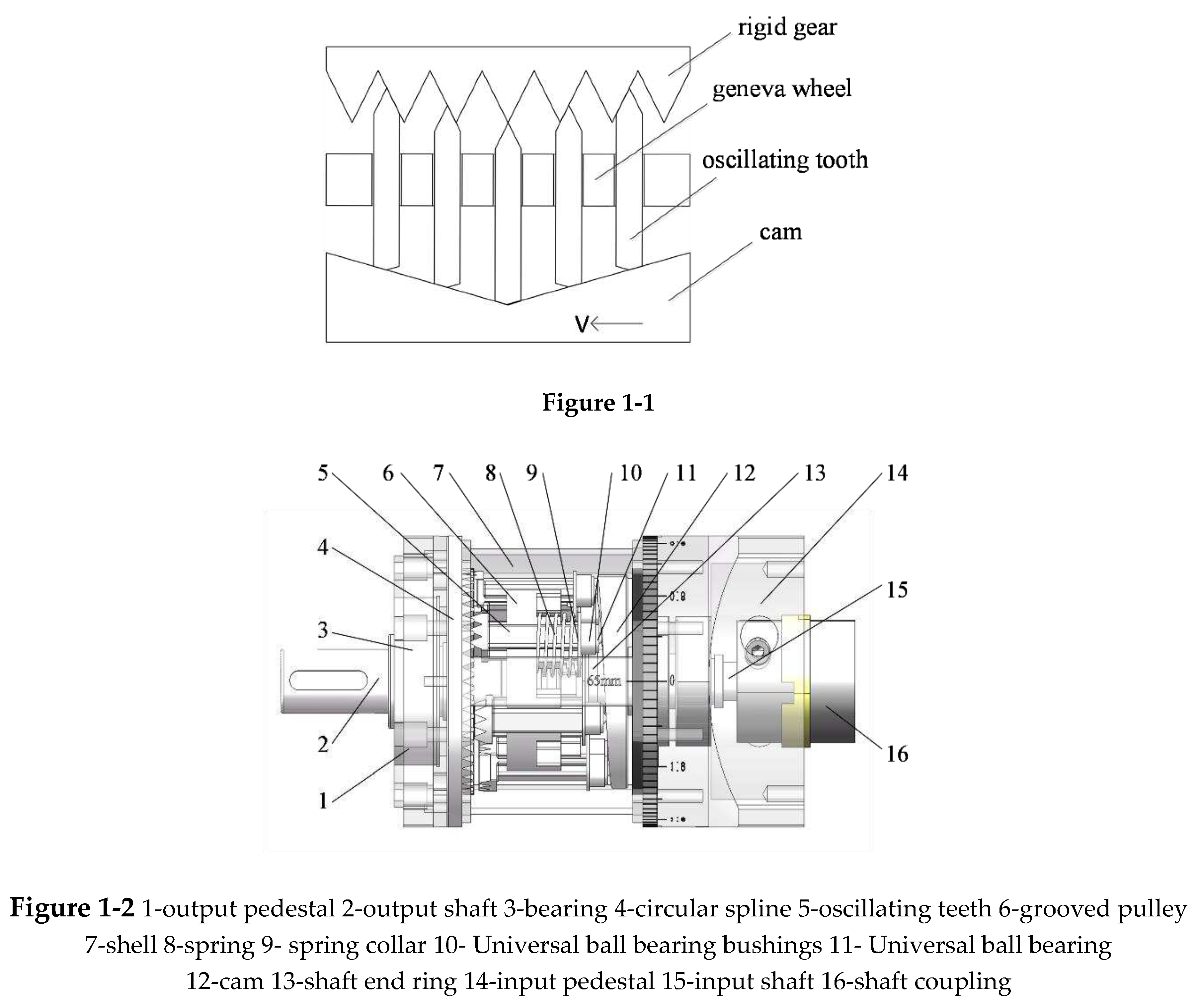
Figure 2.
Force analysis of oscillating teeth.
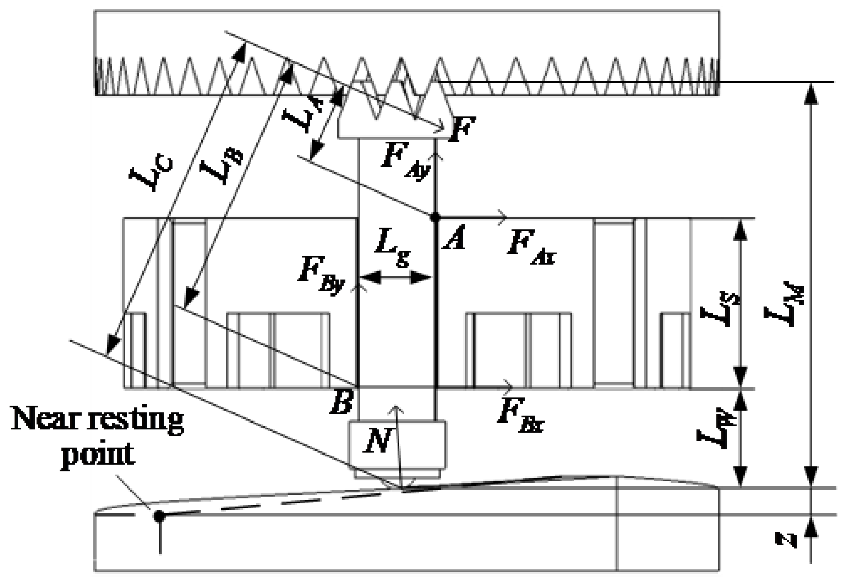
Figure 3.
The meshing relationship between oscillating teeth and the circular spline gear teeth.
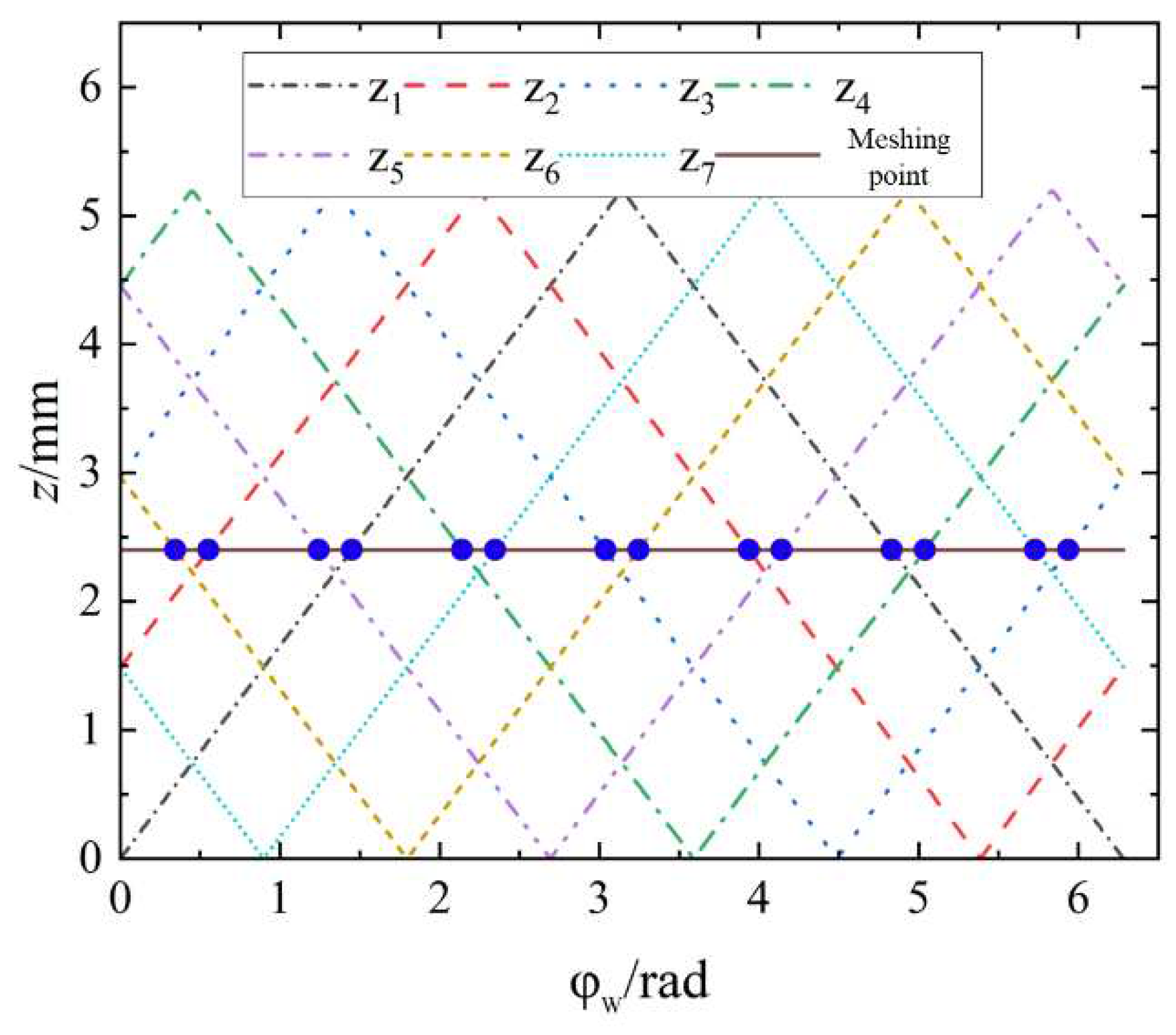
Figure 4.
The force model of the oscillating teeth.
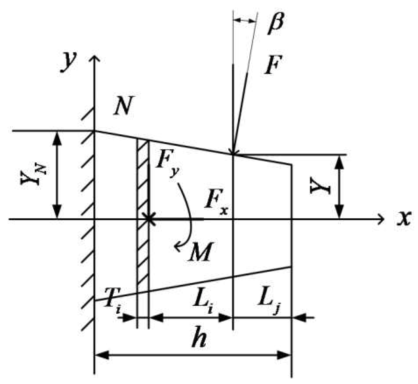
Figure 5.
Compressive stiffness of oscillating teeth.
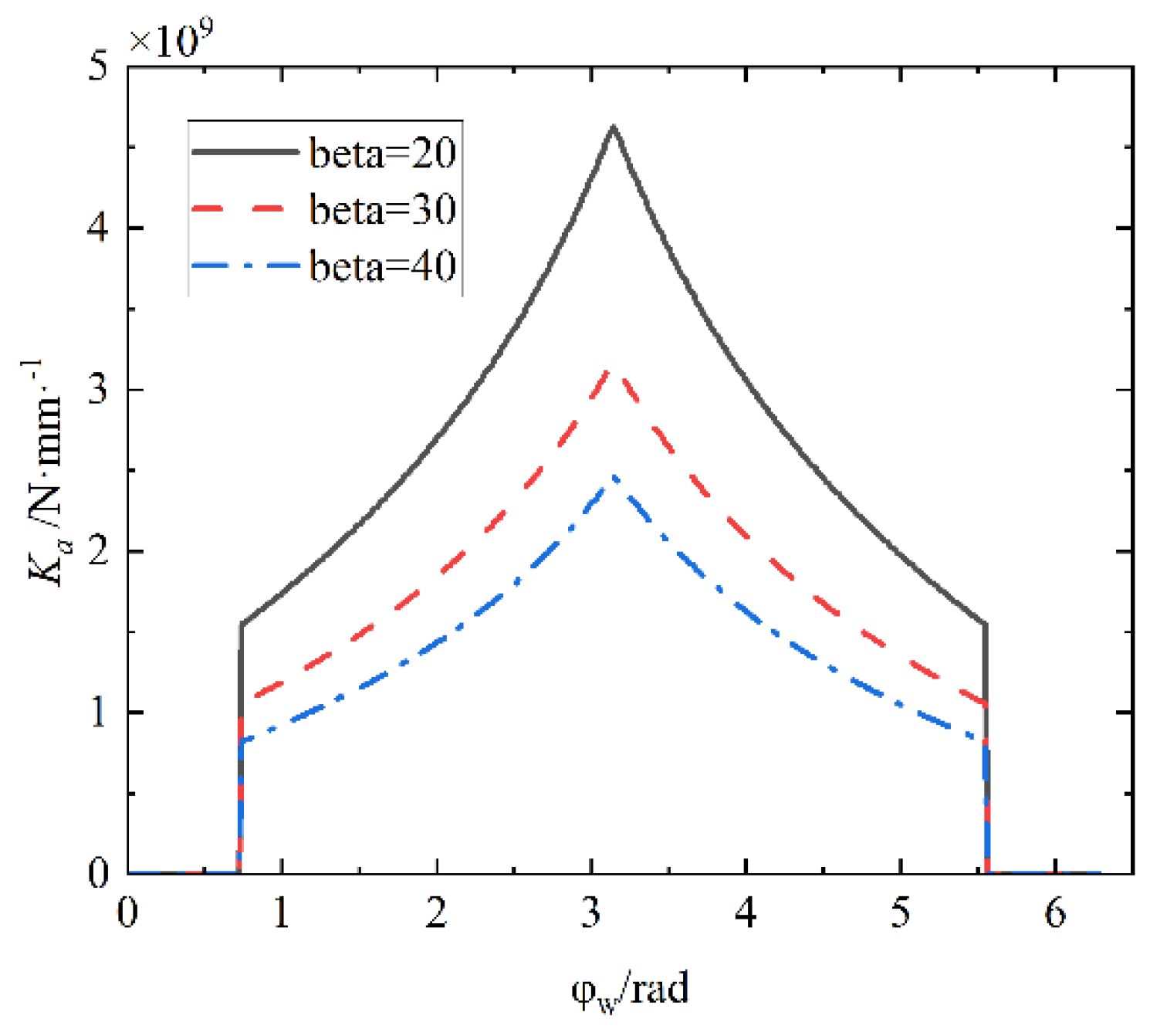
Figure 6.
Bending stiffness of oscillating teeth.
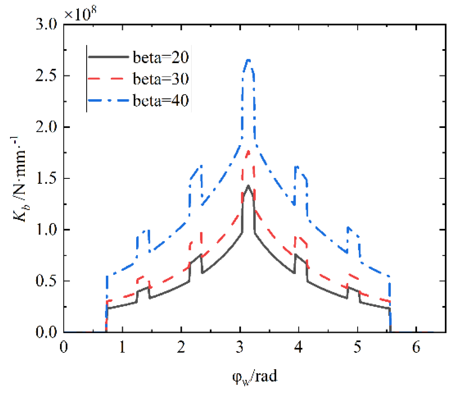
Figure 7.
Shear stiffness of oscillating teeth.
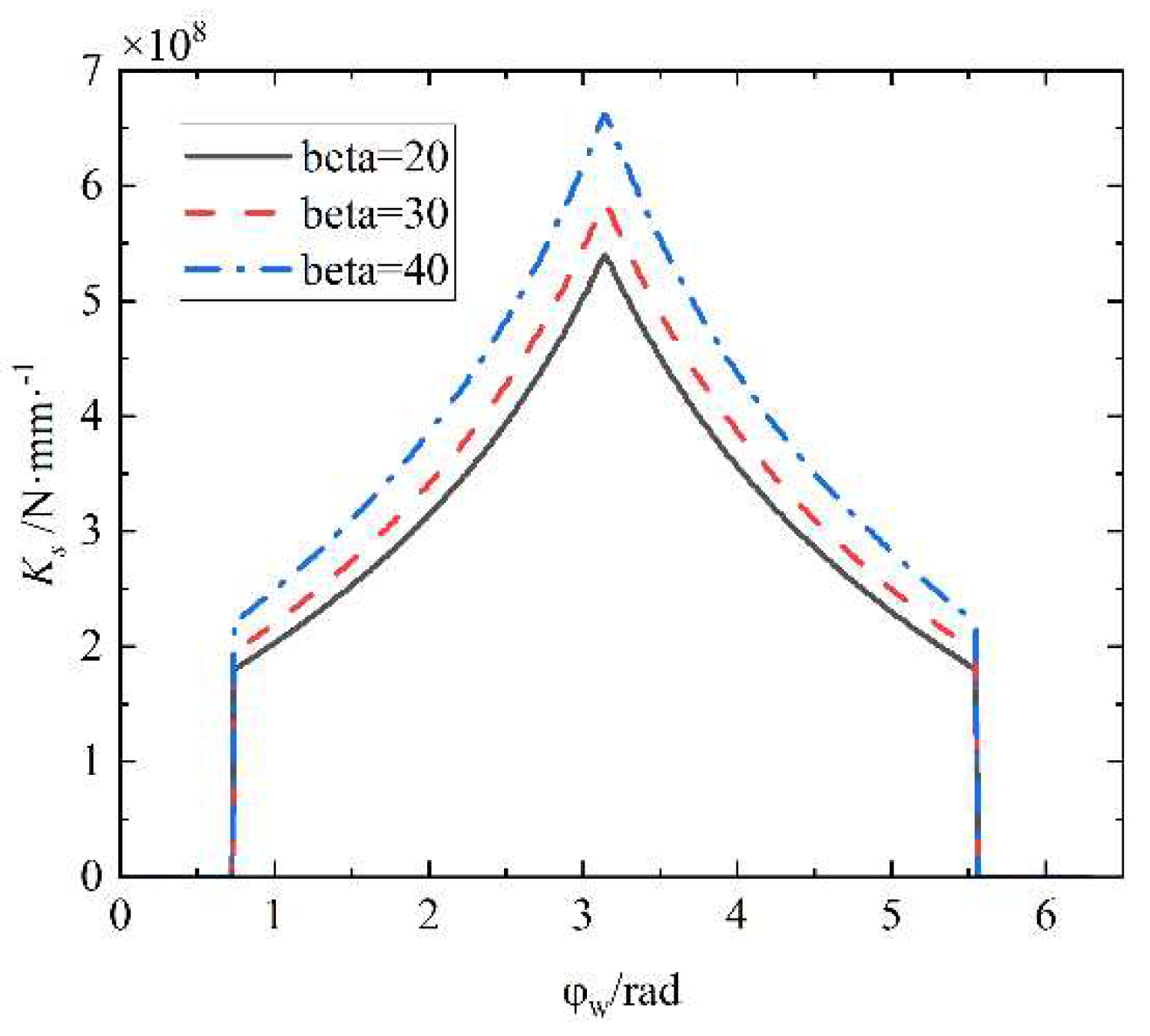
Figure 8.
Base stiffness of oscillating teeth.
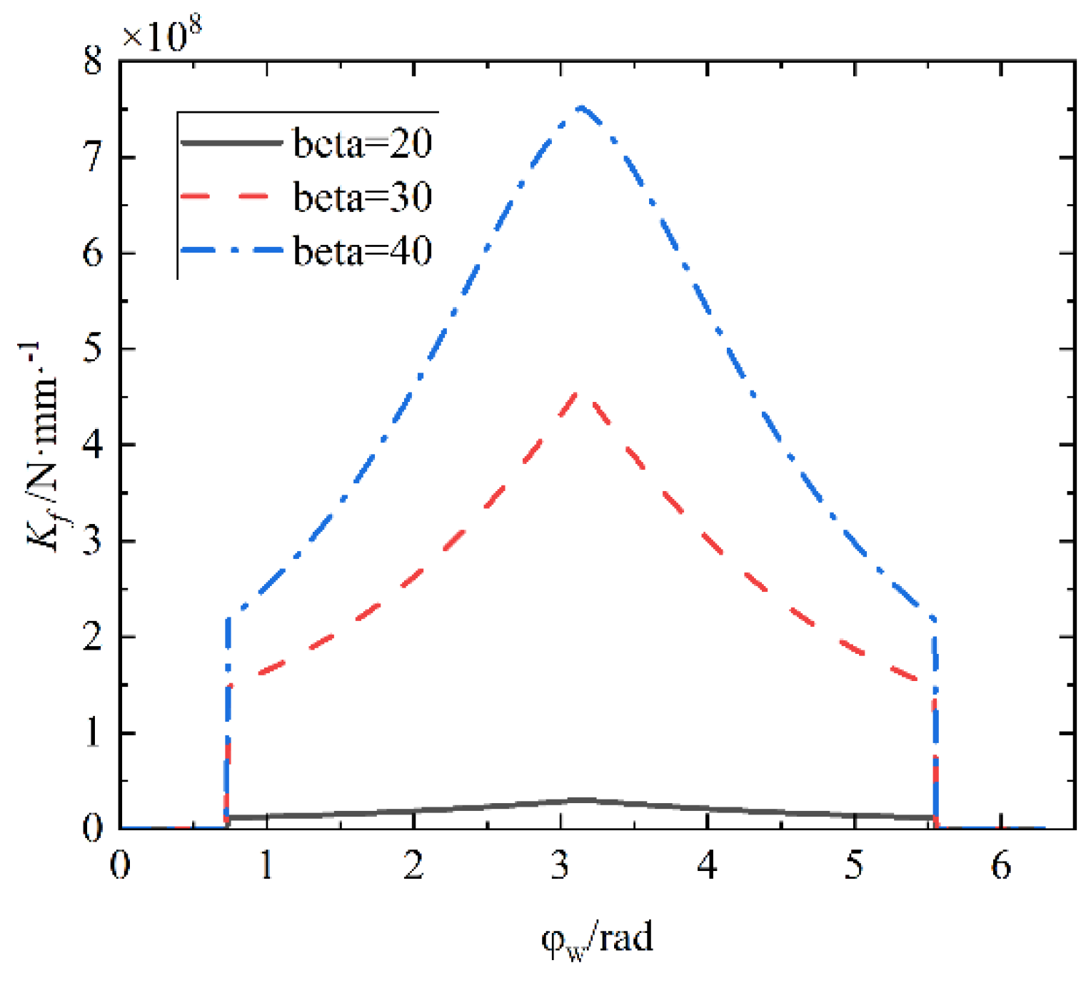
Figure 9.
Contact stiffness of oscillating teeth.
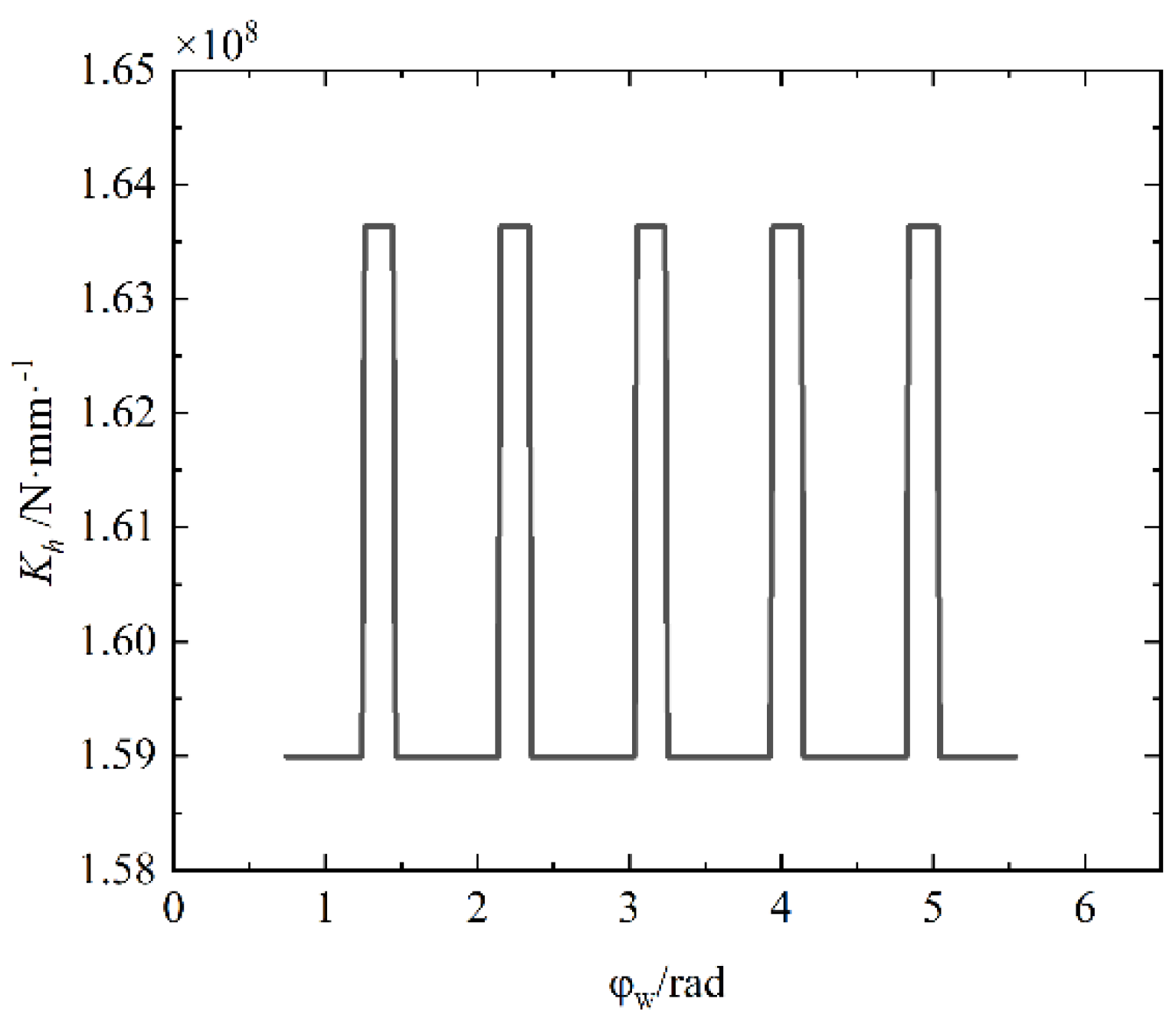
Figure 10.
Comprehensive stiffness of the oscillating tooth.
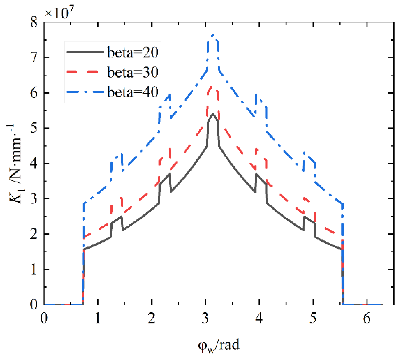
Figure 11.
Figure 11-1 Contact between oscillating teeth and circular spline. Figure 11-2 Contact stress between oscillating teeth and circular spline.
Figure 11.
Figure 11-1 Contact between oscillating teeth and circular spline. Figure 11-2 Contact stress between oscillating teeth and circular spline.
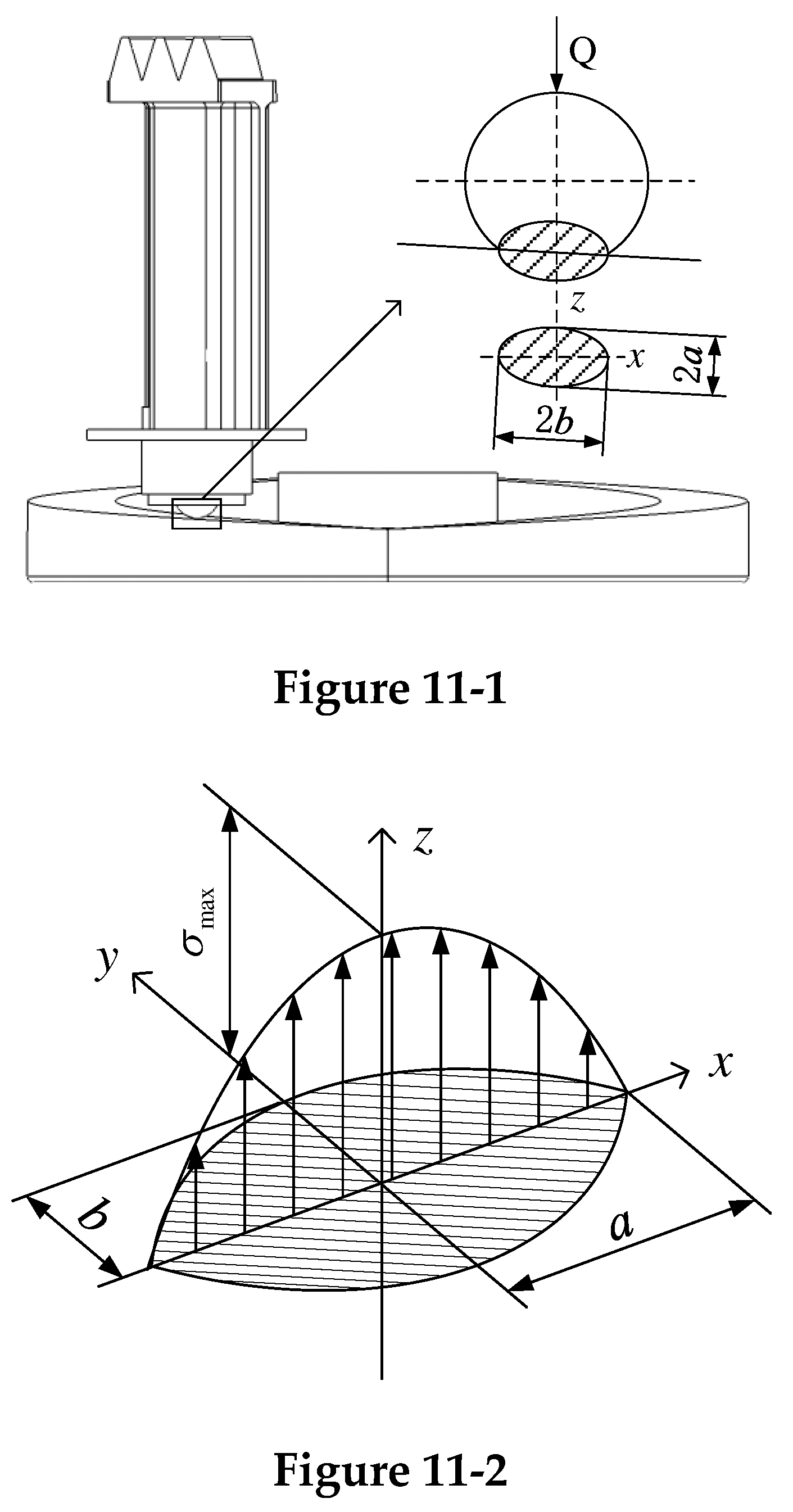
Figure 12.
Figure 12-1 Segmentation of the input. Figure 12-2 Segmentation of the output.
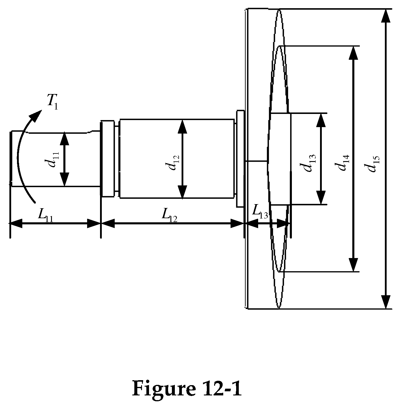
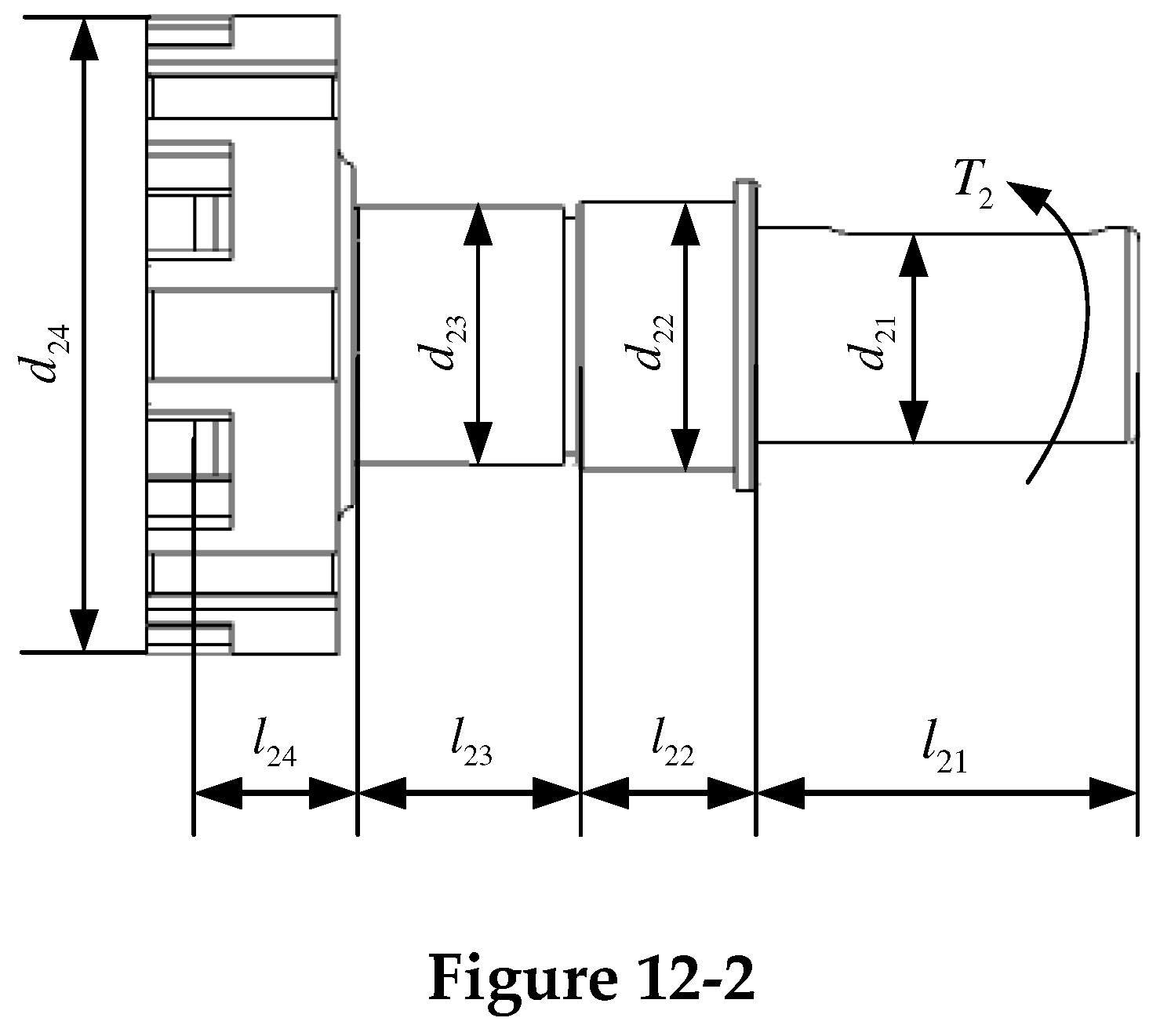
Figure 13.
The diagram of the transmission system dynamic model.
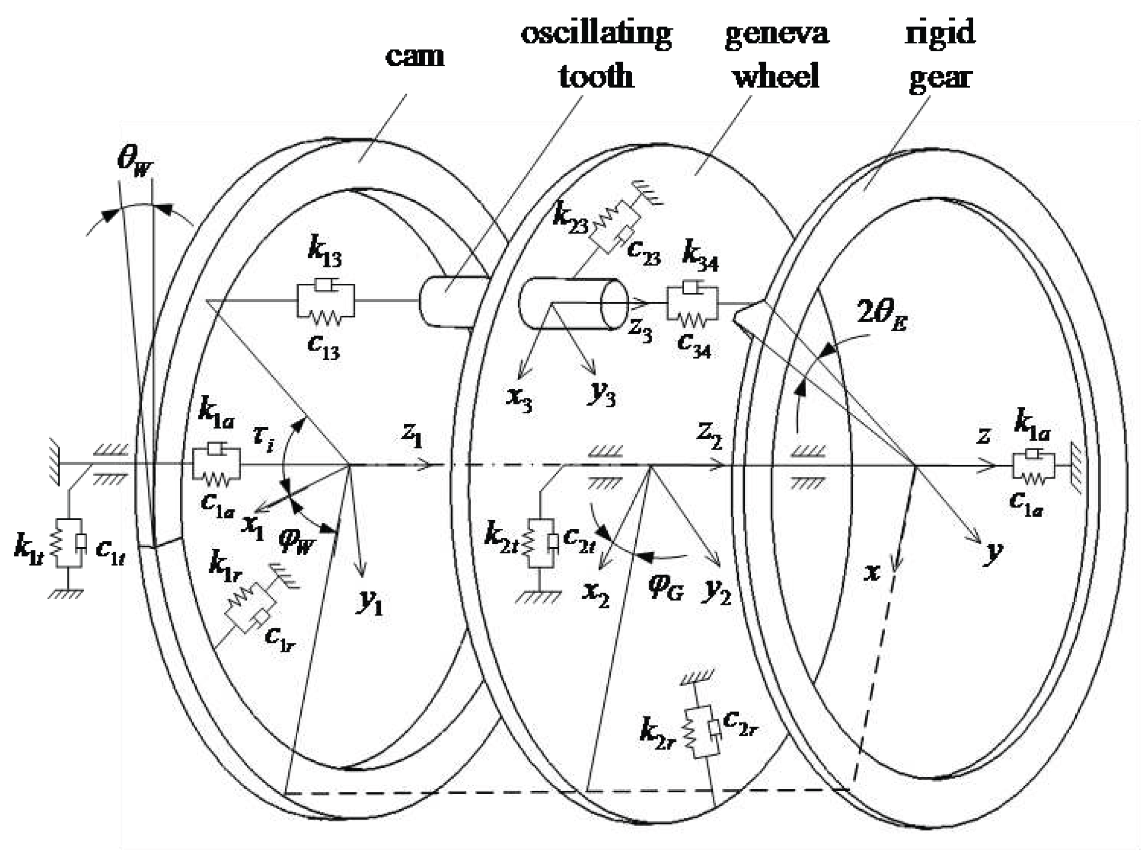
Figure 14.
Simulation values of
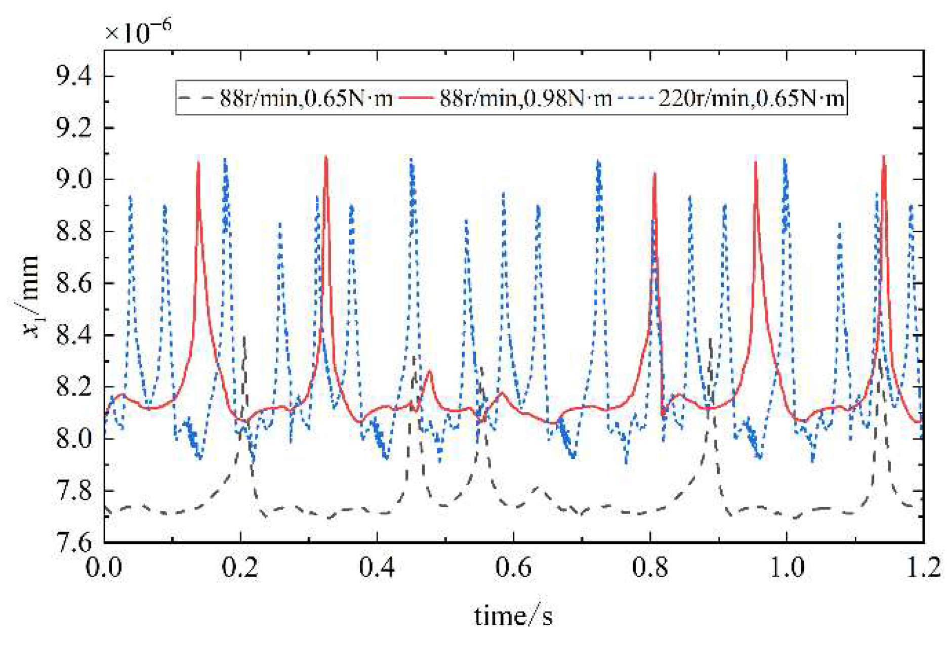
Figure 15.
Simulation values of
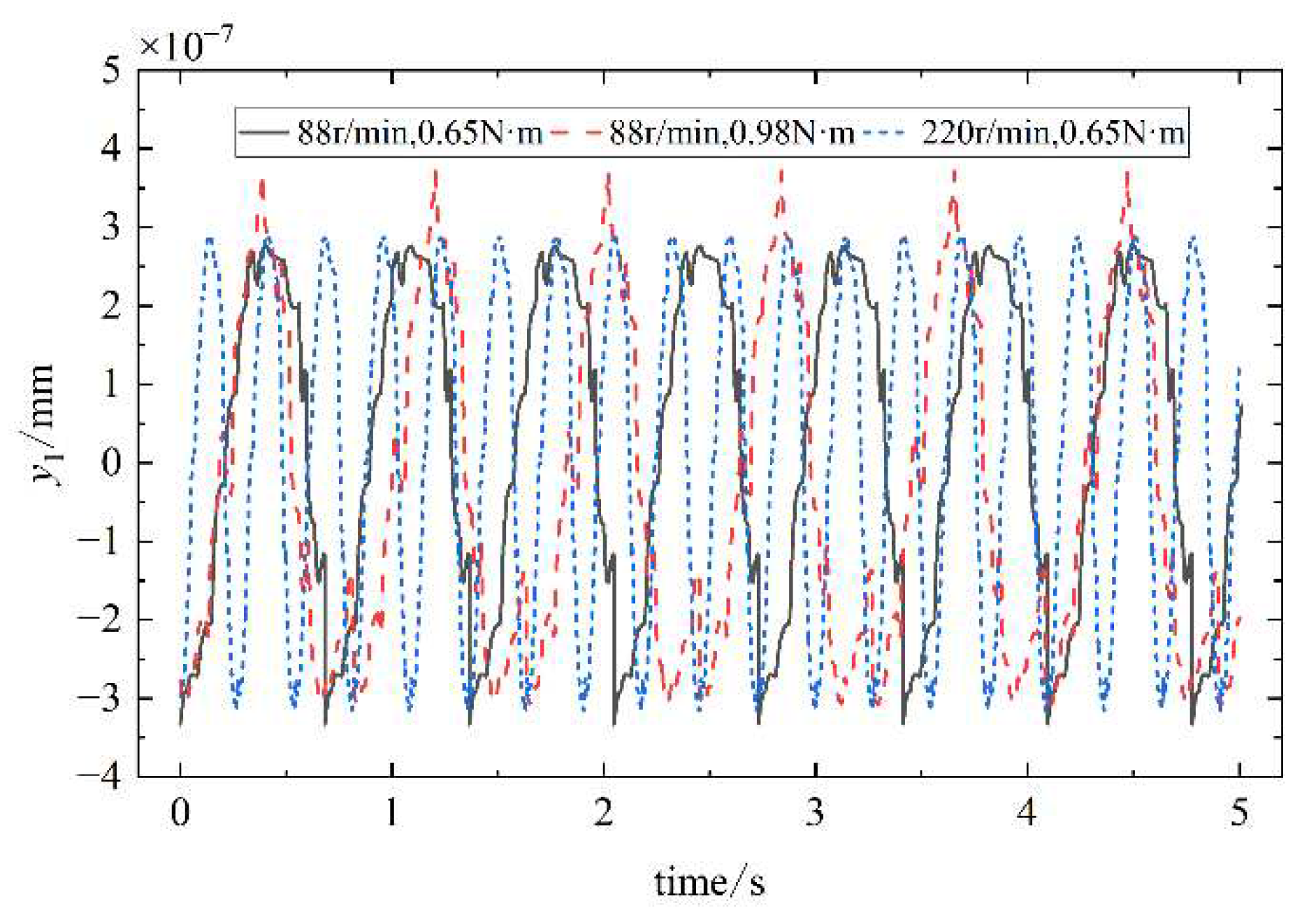
Figure 16.
Simulation values of
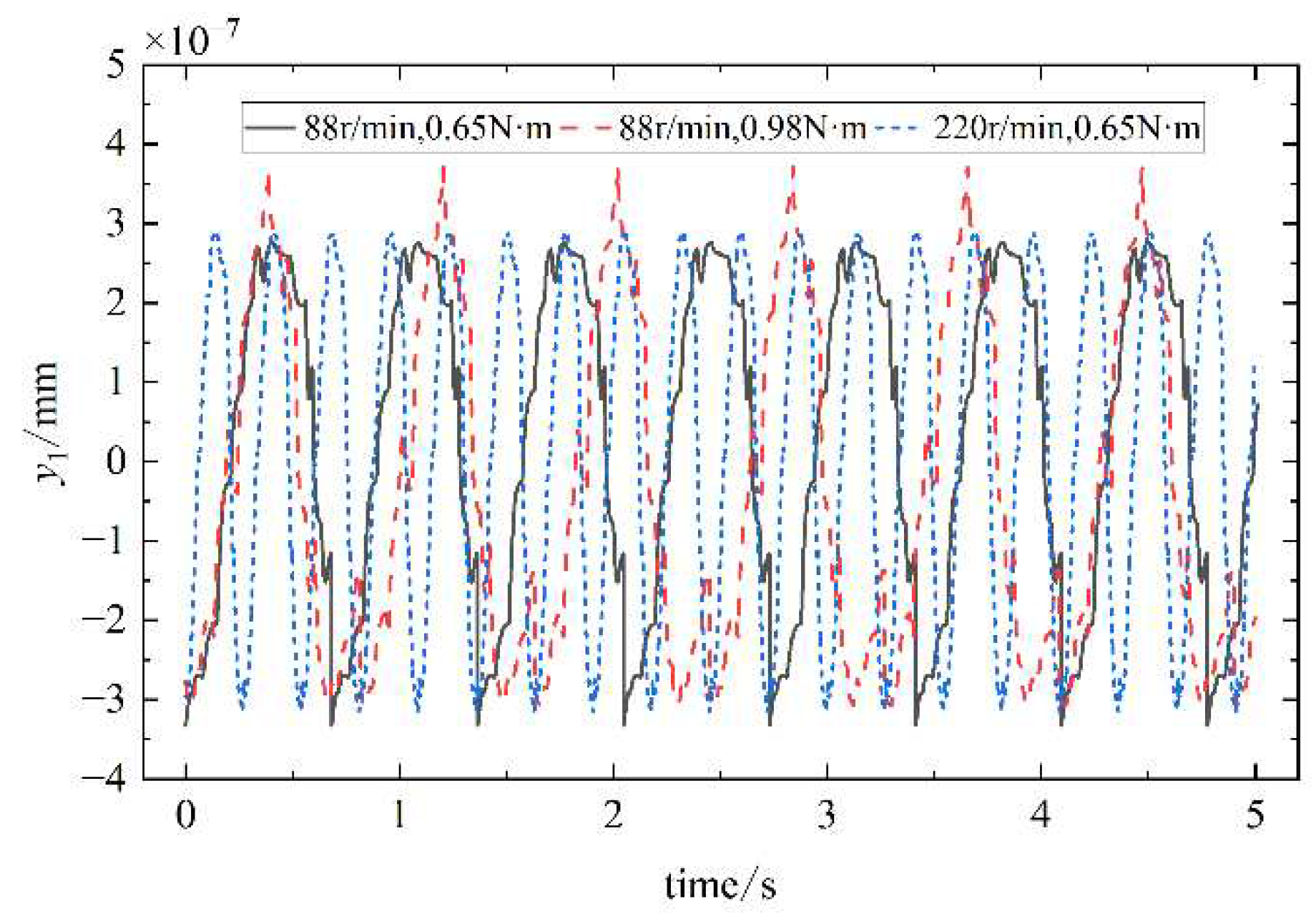
Figure 17.
Simulation values of
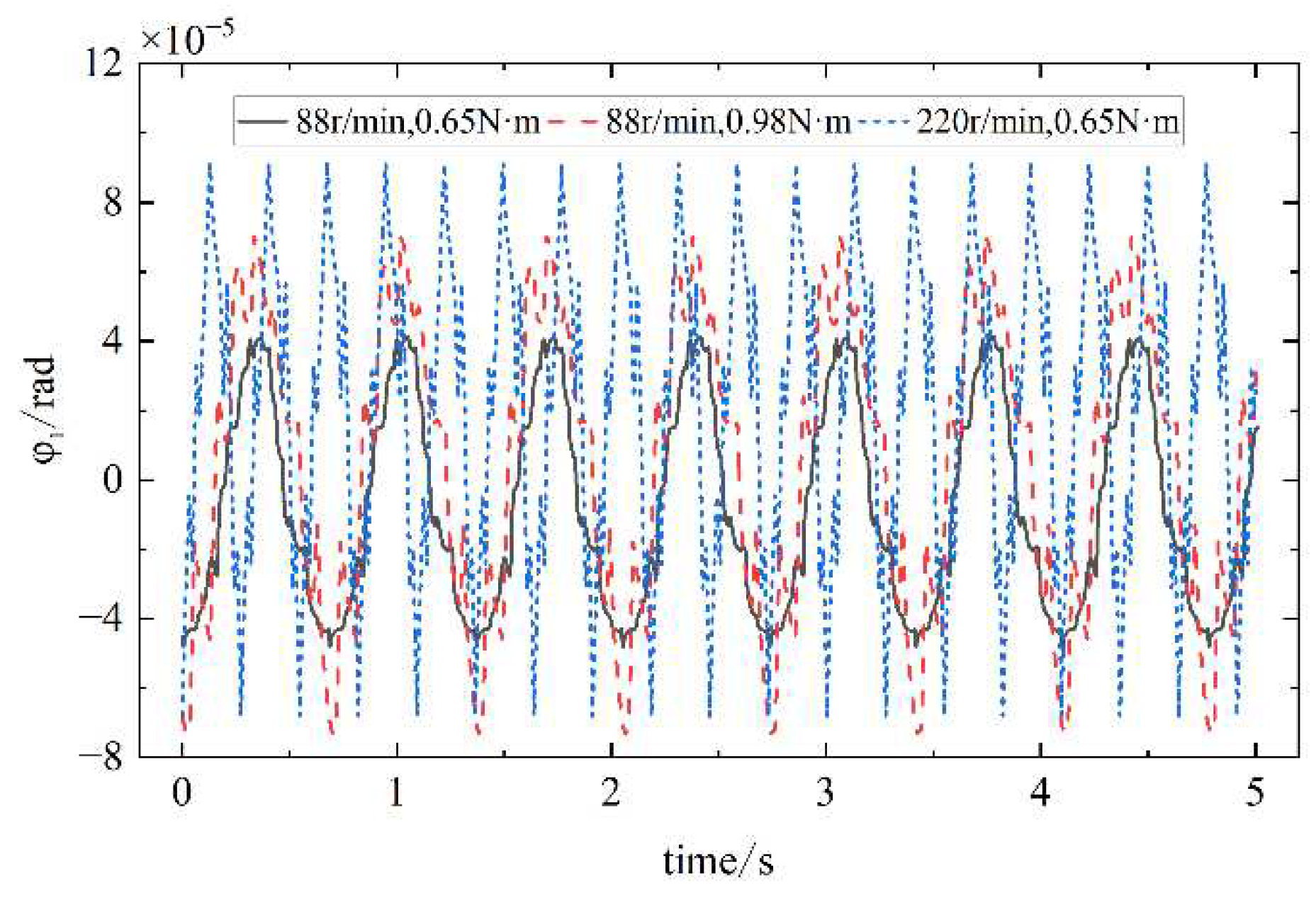
Figure 18.
Simulation values of
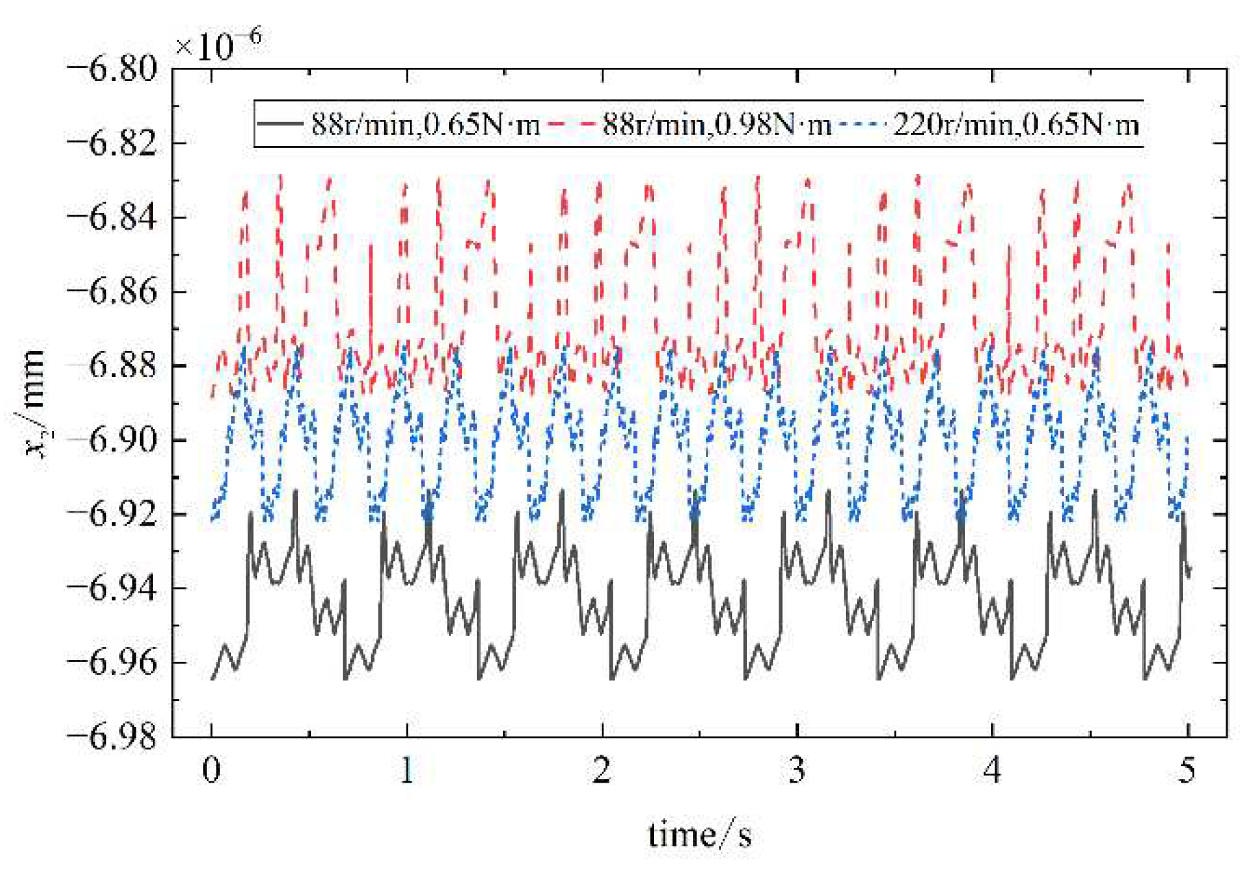
Figure 19.
Simulation values of
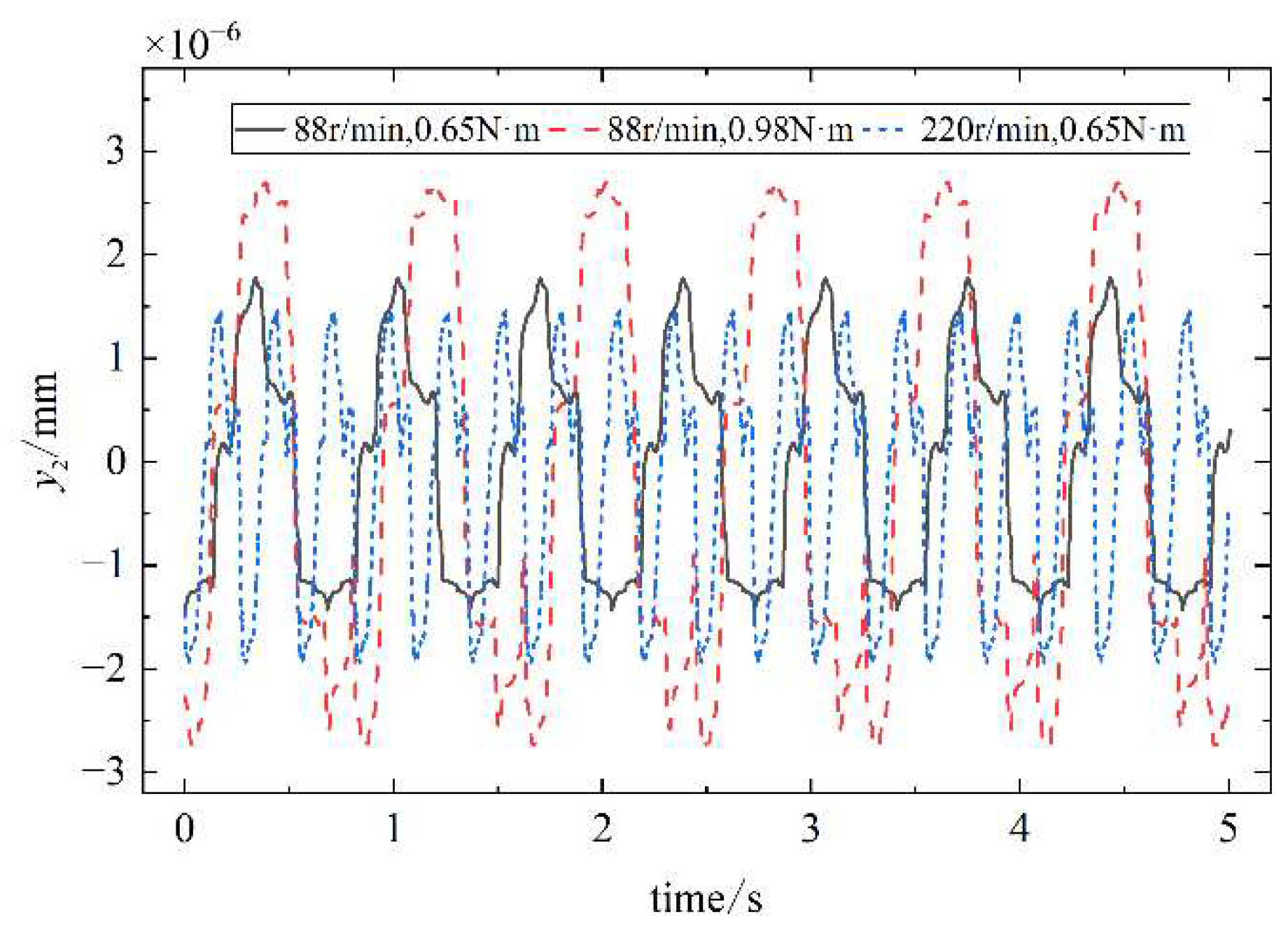
Figure 20.
Simulation values of
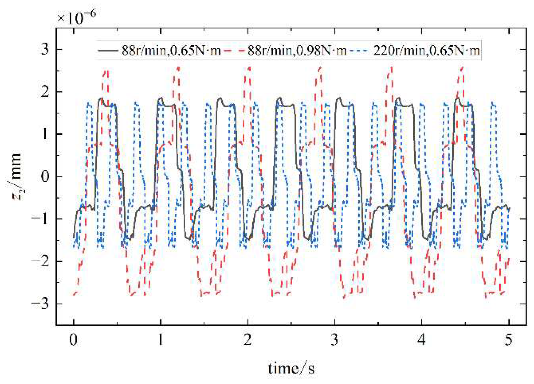
Figure 21.
Simulation values of
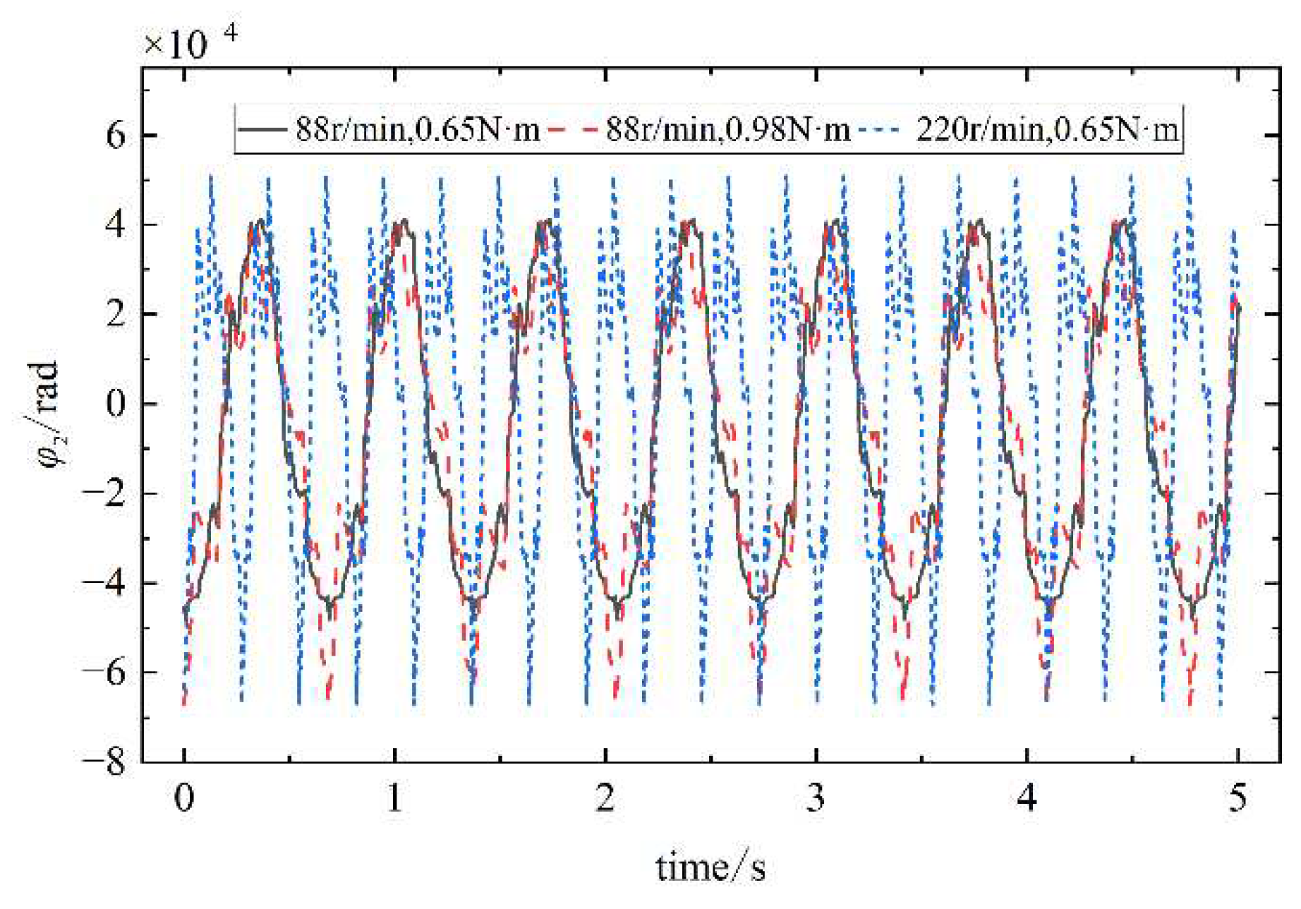
Figure 22.
Simulation values of
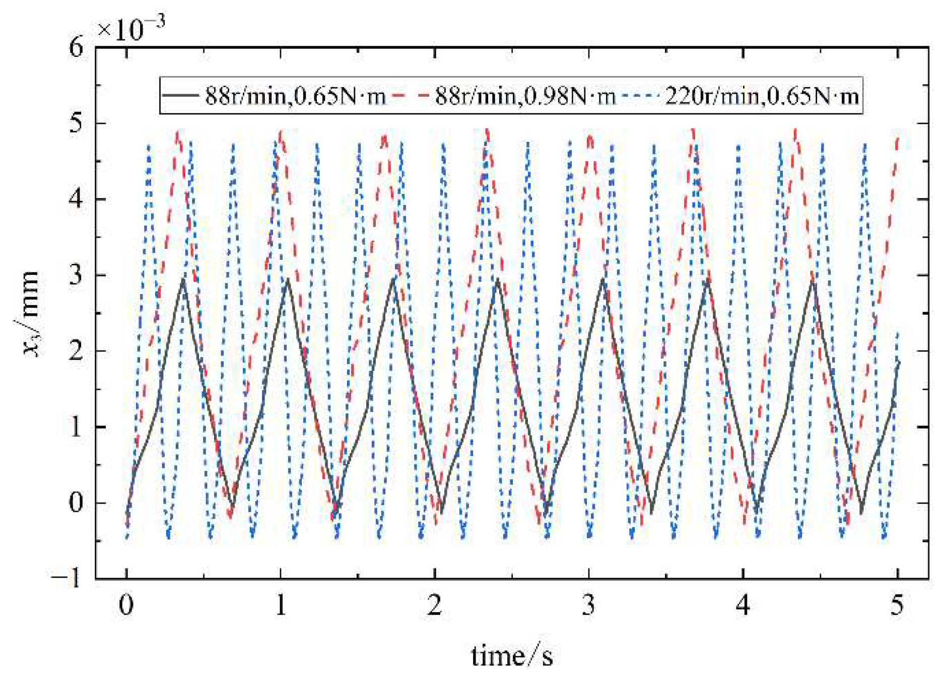
Figure 23.
Simulation values of
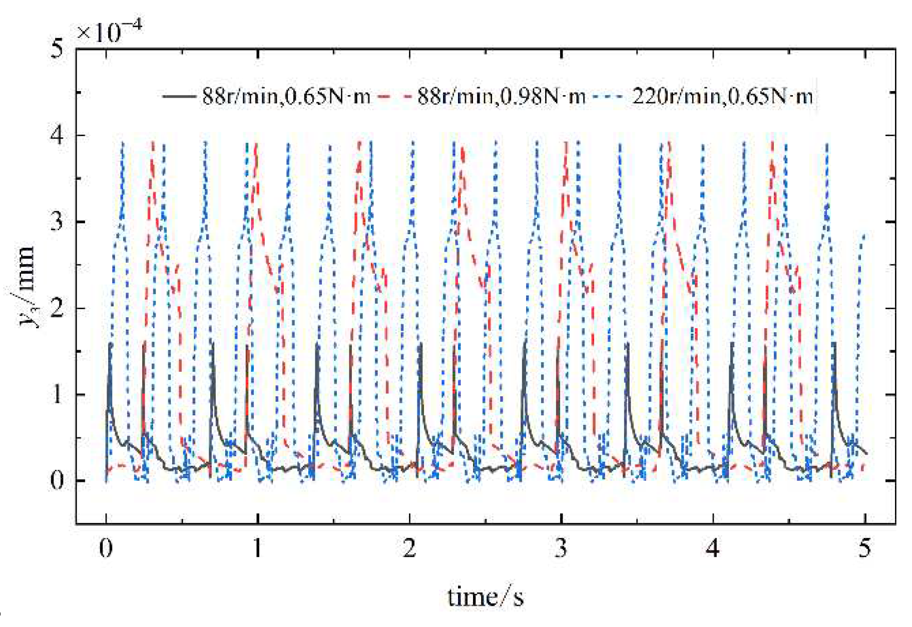
Figure 24.
Simulation values of

Figure 25.
The diagram of the test bench.
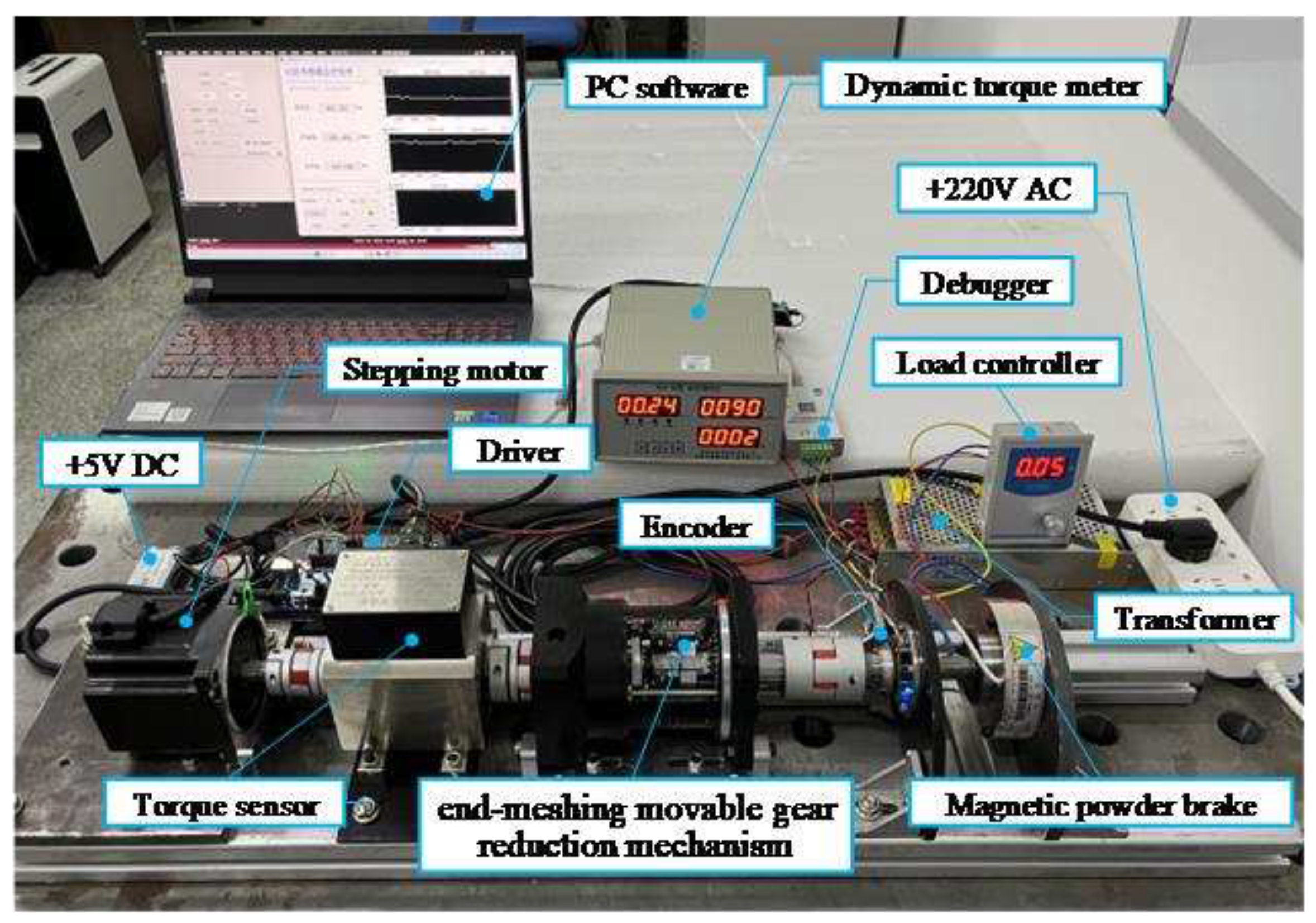
Figure 26.
Comparison of simulation and experimental results for Case 1.
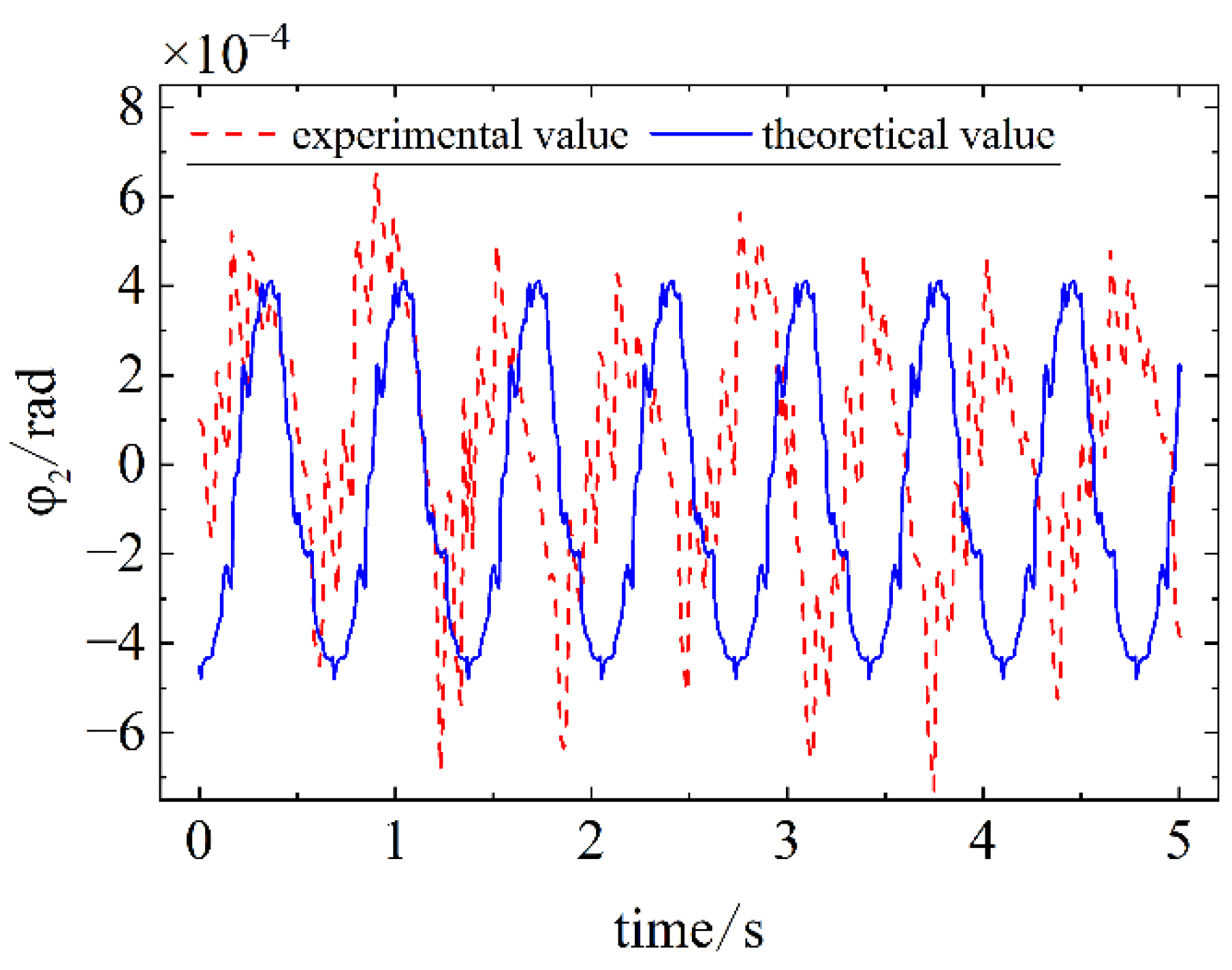
Figure 27.
Comparison of simulation and experimental results for Case 2.
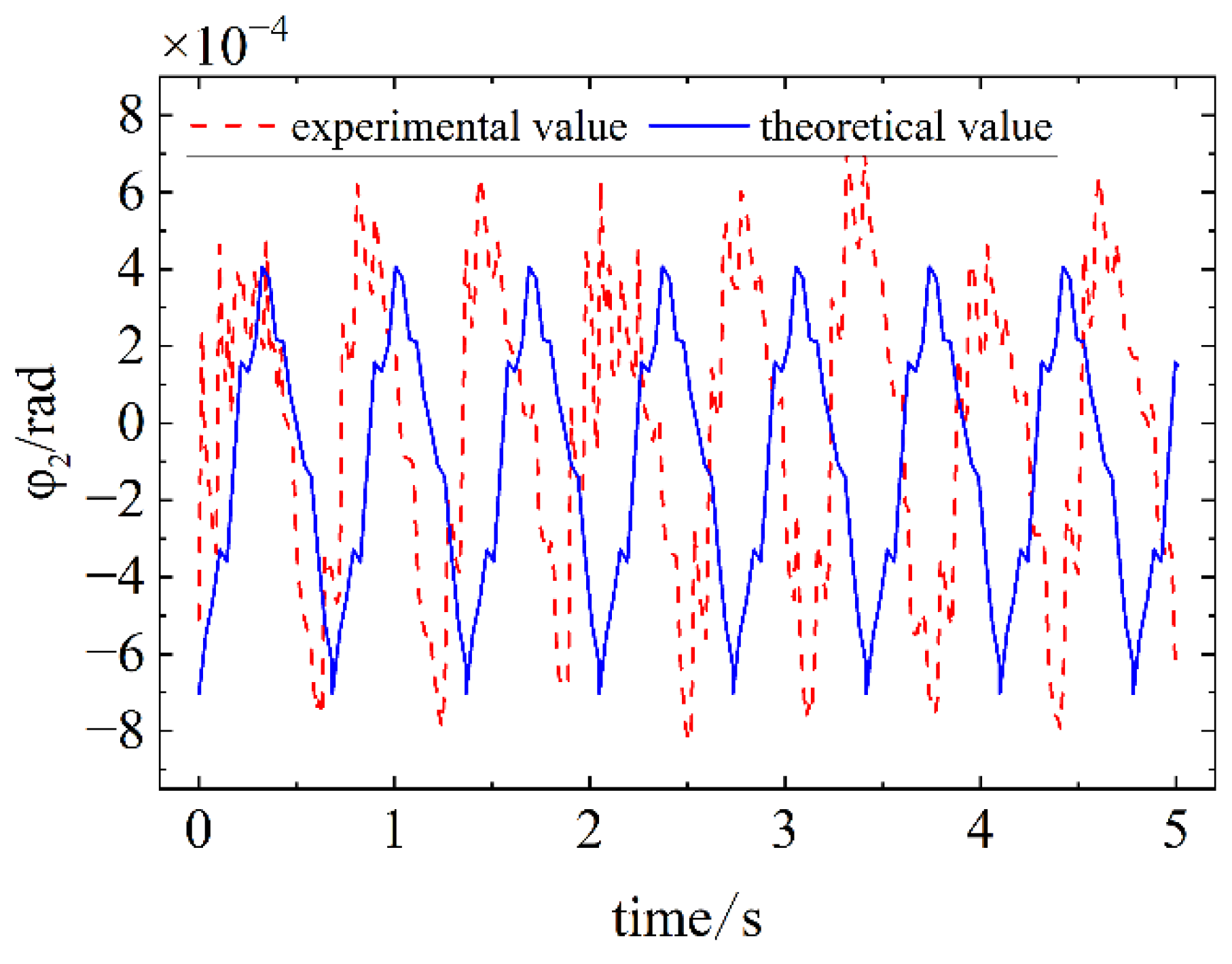
Figure 28.
Comparison of simulation and experimental results for Case 3.
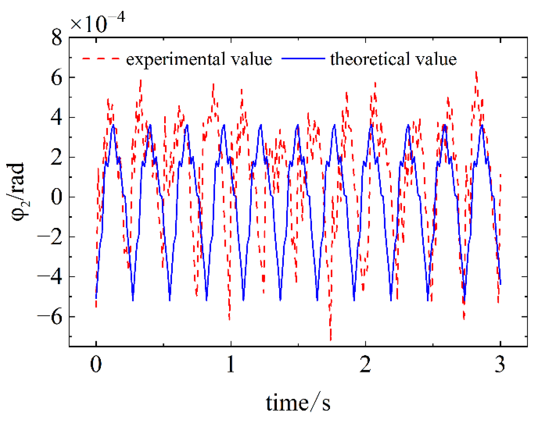
Figure 29.
Comparison of simulation and experimental results for Case 4.
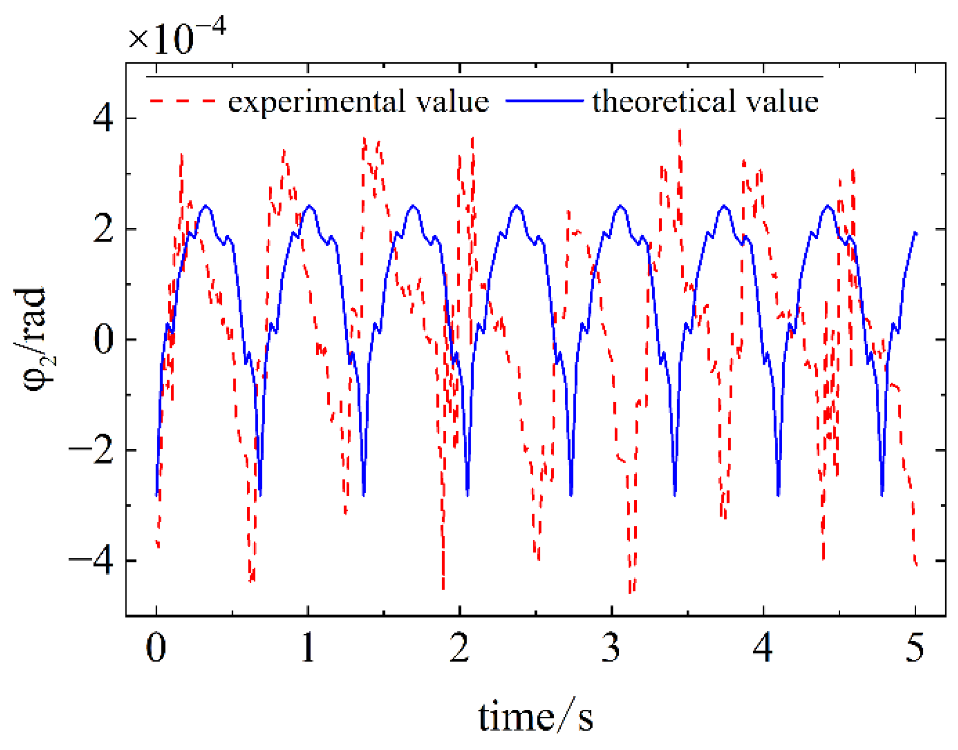
Figure 30.
Comparison of simulation and experimental results for Case 5.
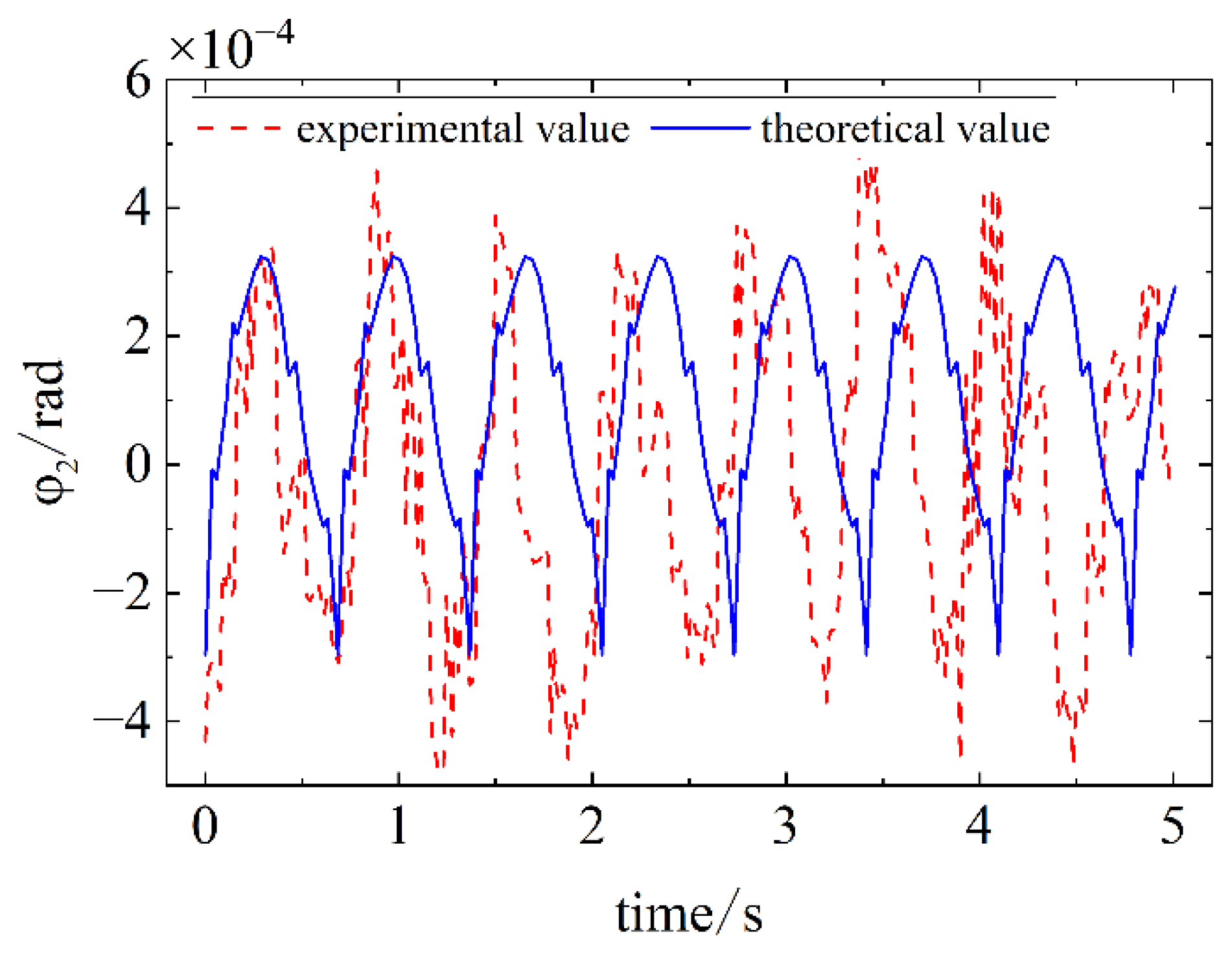

Table 1.
The mass and moment of inertia of each component
| Part name | Mass m(Kg) | Moment of inertia J (Kg×mm2) |
| Cam | 0.12 | 41 |
| Grooved pulley | 0.22 | 54 |
| Oscillating teeth | 0.02 | - |
| Input shaft | 0.08 | 2.6 |
| Output shaft | 0.26 | 145 |
Table 2.
The relevant dynamic parameters setting
| symbol | explanation |
| the meshing stiffness between the oscillating teeth and the cam. | |
| the damping between the oscillating teeth and the cam. | |
| the meshing stiffness between the oscillating teeth and the rigid circular spline. | |
| the damping between the oscillating teeth and the rigid circular spline. | |
| the meshing stiffness between the oscillating teeth and the grooved pulley. | |
| the damping between the oscillating teeth and the grooved pulley. | |
| the radial support stiffness of the cam support systems. | |
| the axial support stiffness of the cam support systems. | |
| the torsional stiffness of the cam support systems. | |
| the radial damping of the cam support systems. | |
| the axial damping of the cam support systems. | |
| the torsional damping of the cam support systems. | |
| the radial support stiffness of the grooved pulley support systems. | |
| the axial support stiffness of the grooved pulley support systems. | |
| the torsional stiffness of the grooved pulley support systems. | |
| the radial damping of the grooved pulley support systems. | |
| the axial damping of the grooved pulley support systems. | |
| the torsional damping of the grooved pulley support systems. |
Table 3.
The relevant parameters in the Figure 13.
Table 3.
The relevant parameters in the Figure 13.
| symbol | explanation |
| the transverse displacement of the cam on the due to vibration. | |
| the longitudinal displacement of the cam on the due to vibration. | |
| the axial displacement of the cam on the due to vibration. | |
| the torsion angle of the cam on the due to vibration. | |
| the transverse displacement of the grooved pulley on the due to vibration. | |
| the longitudinal displacement of the grooved pulley on the due to vibration. | |
| the axial displacement of the grooved pulley on the due to vibration. | |
| the torsion angle of the grooved pulley on the due to vibration. | |
| the transverse displacement of the (i)-th oscillating tooth on the due to vibration. | |
| the longitudinal displacement of the (i)-th oscillating tooth on the due to vibration. | |
| the axial displacement of the (i)-th oscillating tooth on the due to vibration. | |
| the spiral rise angle of the cam profile | |
| the central angle corresponding to the rigid circular spline half-tooth. | |
| the turning radius of the cam. | |
| the turning radius of the grooved pulley. | |
| the cam rotation angle. | |
| the grooved pulley rotation angle. | |
| the relative rotation angle between and . |
Disclaimer/Publisher’s Note: The statements, opinions and data contained in all publications are solely those of the individual author(s) and contributor(s) and not of MDPI and/or the editor(s). MDPI and/or the editor(s) disclaim responsibility for any injury to people or property resulting from any ideas, methods, instructions or products referred to in the content. |
© 2024 by the authors. Licensee MDPI, Basel, Switzerland. This article is an open access article distributed under the terms and conditions of the Creative Commons Attribution (CC BY) license (http://creativecommons.org/licenses/by/4.0/).
Copyright: This open access article is published under a Creative Commons CC BY 4.0 license, which permit the free download, distribution, and reuse, provided that the author and preprint are cited in any reuse.


