1. Introduction
The advancement of space technology has brought to the forefront a range of critical challenges, such as spacecraft maintenance and rescue in orbit [
1], the removal of space debris [
2], satellite rendezvous and docking [
3], companion flight monitoring, and in-orbit capture [
4]. These are urgent problems that demand effective solutions. Key to the successful execution of in-orbit missions is target recognition and pose measurement, which play pivotal roles [
5]. Many of the targets in these missions are non-cooperative, lacking known structural, size, or motion information, and often without cooperative markers or communication capabilities with tracking spacecraft. Identifying and measuring non-cooperative targets poses a significant and challenging task [
6,
7].
Target detection can usually be divided into three stages in space [
8]: long-distance (hundreds of meters to tens of kilometers), mid-distance (several kilometers to tens of meters) and close-distance (a few hundred meters to several meters). Generally, the first two stages usually use microwave radar and lidar to detect the approximate location information of the target. They have advantages in long-distance measurement, but the measurement accuracy is low and it is difficult to obtain attitude information [
9,
10]. For close-distance target detection, visual measurement equipment are usually used to provide the position and attitude information of targets. This article focuses on the pose measurement of non-cooperative spacecraft in short distance.
Some space programs and research departments have adopted a number of methods for close target detection. The Canadian Space Agency and NASA jointly developed triangulation LIDAR for the close-range measurement. But the point cloud matching database needs to be pre-trained [
11,
12]. Liu used flash laser radar to generate point cloud data, and proposed a pose tracking method based on the known satellite model [
13]. Tzschichholz measured the non-cooperative targets by comparing the 3D point cloud features observed by the ToF camera with the actual 3D models [
14]. Klionovska used the ToF camera to detect the non-cooperative targets combining target 3D model [
15]. Gao et al. proposed an algorithm for measuring the position and attitude of targets using a monocular camera and a laser rangefinder [
16]. The ranging accuracies of the pose measurement technique based on lidar and vision are usually respectively centimeter and millimeter. In order to achieve fine work at close range, visions are often chosen as the solution. We typically want to transfer images from on-orbit operations back to the ground for preservation and analysis [
17]. Therefore, satellites are usually equipped with cameras (with different optimal imaging distances and observation directions), and no additional equipment is required. It is difficult for monocular vision to measure the pose of the target without prior information. As for the multi-vision, the object information obtained has more redundancy, which can enhance robustness and measurement accuracy of the system, while the cost price is higher and the operation speed is relatively slow. Binocular visions are widely concerned by researchers because of its balance between detection accuracy and operation speed.
There are some examples of binocular stereo vision used to detect non-cooperative targets. There are two main types of target detection methods. The first one is using deep neural network models to achieve target detection and pose estimation [
18,
19]. Daigo proposed the AI-assisted near-field pose estimation method of spacecraft whose shape and size are completely known. This method detected the keypoints of spacecraft with machine learning techniques and solve the pose by the Efficient Perspective-n-Point (EPnP) algorithm and particle swarm optimizer (PSO) method [
20]. Different deep learning approaches have more or less the following problems. Pre-training is expensive and difficult to cover a variety of targets. It requires high computing power of the onboard computer. Many researches are focused on target detection, and there are few researches on target pose solving. The second method relies on image processing techniques to identify the salient features of the target, including but not limited to triangular brackets [
21], rectangular solar panels, and circular engine nozzles [
22]. Xu introduced a binocular measurement approach for assessing the interface ring and engine nozzle of rockets [
23], while Peng devised a virtual stereo vision measurement method reliant on the interplay of triangular and circular features, albeit with the need for manual selection of interior points [
24]. Additionally, Qiao proposed a relative pose measurement technique based on point features [
25], but it necessitates prior knowledge about the target. Feature-based Target measurement based on feature detection is susceptible to environment and illumination. But it has the advantages of fast computing speed and low cost.
This paper takes the method of identifying the salient features of the target. In theory, larger target features tend to yield higher recognition success rates. Therefore, this paper focuses on researching the aircraft body or rectangular solar panel, which represents the most prominent area within the target. The surface shapes of the aircraft body and the solar panels are usually rectangles. A stereo vision detection method for rectangular features is studied in this paper. The detection of rectangular features in both space and ground applications typically involves processes such as edge line feature extraction, template matching, rectangle fitting, and minimum rectangle envelope extraction. Solar panels consist of numerous small rectangular photo receptors, resulting in a multitude of straight-line features. Extracting these straight-line features is time-consuming, and accurately discerning the target lines can be challenging. Template matching demands prior knowledge of the target, so it is not suitable for the non-cooperative spacecraft detection. Regarding rectangular fitting or minimal rectangular envelope extraction, the accuracy of these methods is limited due to the distortion of rectangular features in Cartesian space when projected onto the image plane [
26,
27,
28]. The error is large in fitting the contour by means of rectangular envelope.
Through the subsequent analysis, it can be found that the projection of the rectangular feature on the image plane is approximately parallelogram. Therefore, we study the parallelogram fitting method of rectangular features and apply it to non-cooperative spacecraft detection. The algorithm has following advantages: (1) The algorithm has strong adaptability and can be used to detect rectangular features that most spacecrafts have; (2) The calculation efficiency of the algorithm is high, because the fine elements and interference elements inside the shape envelope will be gradually eliminated during operation, greatly reducing the amount of calculation; (3) The algorithm has high fitting accuracy. It combines the imaging characteristics of rectangular features. The major contributions of this paper are presented as follows: (1) The imaging characteristics of rectangles, which are the typical natural characters, in the image plane are analyzed. A parallelogram fitting method for rectangular features in the image plane is proposed; (2) The parallelogram fitting method is applied to the measurement of non-cooperative spacecraft. Natural features on non-cooperative targets such as spacecraft bodies and solar panels are detected and measured without adding additional cooperative markers.
This paper is organized as follows:
Section 2 outlines the mission of detecting non-cooperative spacecraft and proposes the framework of this paper’s non-cooperative spacecraft measurement method.
Section 3 demonstrates the properties of rectangular features when projected onto the image plane. In the fourth section, we introduce the parallelogram fitting algorithm for rectangular features in Cartesian space. Section five presents the pose solution algorithm for non-cooperative space targets. The sixth section describes the establishment of an experimental system to evaluate our proposed method. Finally, the last section provides a summary of the paper and draws conclusions.
2. Space On-Orbit Measurement Tasks and Version Measurement Algorithm Framework
2.1. Space On-Orbit Measurement Tasks
Figure 1 shows the process of detecting and approaching a non-cooperative spacecraft during on-orbit operation. The servicing satellite detects the target satellite from long distance like hundreds of meters to tens of kilometers or predict the target satellite’s orbit. The servicing satellite monitors the target at long-distance or mid-distance and reconstructs the target point clouds. In the whole space on-orbit service process, this paper focuses on the final tracking phase, that is, the Euler distance between the target and the service star is between 1m to 30m. The stereo camera is mounted on the servicing satellite. This camera is utilized to observe the non-cooperative target satellite and compute its position and orientation, which in turn is used to plan the movements of the control satellite.
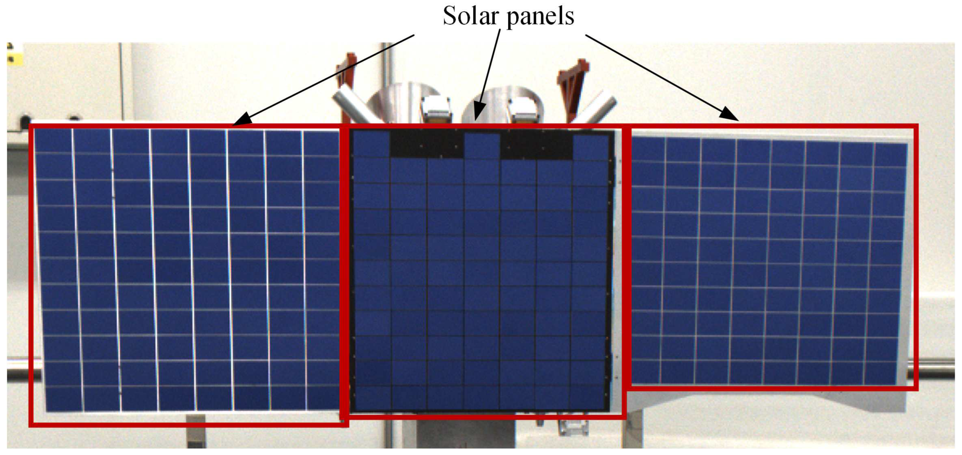
In the space environment, lighting conditions are both harsh and subject to rapid changes. To ensure effective detection, it is prudent to choose the most prominent target on the satellite, as depicted in
Figure 2. The solar panel, with its expansive surface area and conspicuous visibility when deployed, emerges as the optimal choice for visual detection. Notably, solar panels typically exhibit a rectangular plane surface, rendering them an ideal fit for the parallelogram fitting method introduced in this paper.
2.2. Overview of the On-Orbit Pose Measurement Method
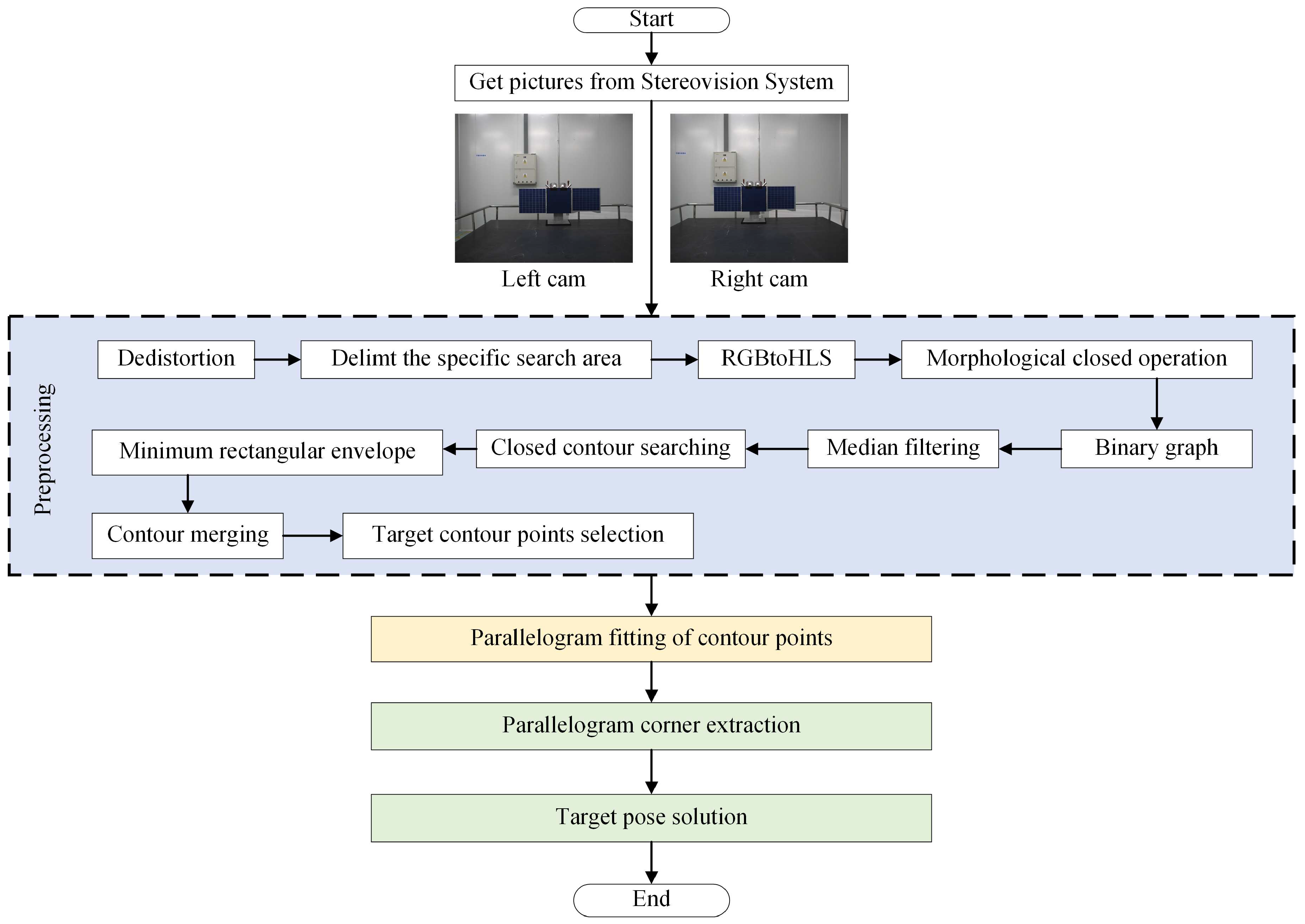
The process of the pose measurement algorithm for non-cooperative targets is shown in
Figure 3. It comprises the following steps:
Step 1: After capturing the image of the non-cooperative target using a stereo camera, the image distortion is corrected based on pre-calibrated camera parameters.
Step 2: In the initial detection phase, search for the satellite across the entire image. To enhance algorithm speed, the region of interest (ROI) can be defined based on previous measurement results in subsequent detections.
Step 3: Convert the image to the HLS format and apply median filtering.
Step 4: Set detection criteria based on the HLS values of each pixel, extract the target region, and convert it into a binary image.
Step 5: To minimize interference from silicon wafer gaps on the extracted image’s integrity and improve the extraction of the solar panel, perform morphological closing on the binary map.
Step 6: Search for closed contours in the image and fit these contours with minimum rectangular envelopes.
Step 7: Since the solar panel might have internal interference, it may be divided into multiple contours. Fit rectangles to each contour. Merge contour points based on the center point distance of each rectangle and the rectangle side length. Then, fit the minimum rectangle to the newly generated point set. Repeat this step until no further contour merging is possible.
Step 8: Select target contour points based on contour size, the area relationship between the contour and the rectangle, and the shape of the fitted rectangle.
Step 9: Utilize the parallelogram fitting algorithm proposed in this paper to fit the contour points and identify the corner points of the fitted quadrilateral.
Step 10: Solve the pose of the non-cooperative satellite in Cartesian space relative to the stereo vision system based on the corner points.
3. Planar Projection Properties of Rectangular Features
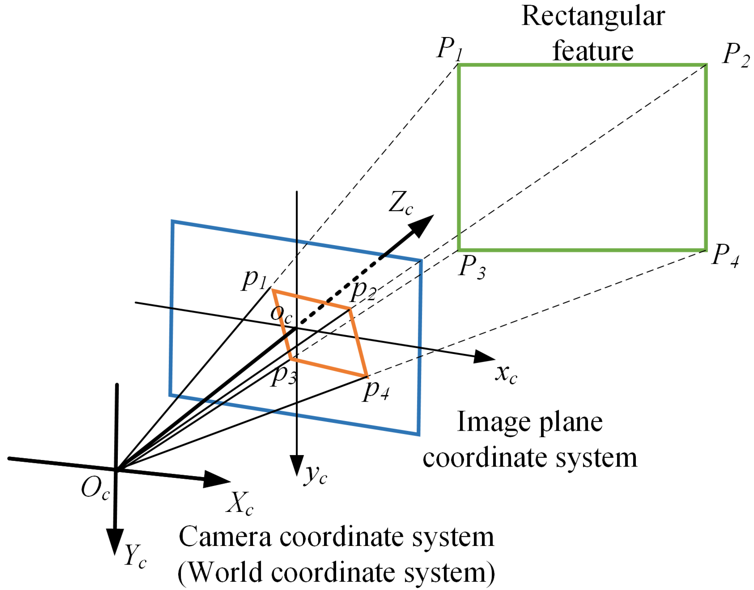
The majority of cameras operate on a center projection model, where features from Cartesian space are subject to distortion upon projection onto the camera’s image plane. The characteristics of rectangular features when projected onto the camera image plane are illustrated as follows. The projection of a rectangle from Cartesian space onto the image plane of the camera is depicted in
Figure 4. The camera coordinate system
-
is taken as the world coordinate system, and the coordinate of Cartesian space rectangle
in the camera coordinate system is (
,
,
) (
n = 1,2,3,4). The coordinates they project into the image plane
-
are
(
,
) (
n = 1,2,3,4). According to the principle of central projection:
Where,
f is the focal length of the camera.
Rectangular features in 3D space have the following two properties when projected to 2D image plane:
Property 1: Vertical segments in the same plane in Cartesian space are not necessarily vertical in the image plane.
prove: In the camera coordinate system,
, so:
In the image plane:
In general, the distance between the target and the camera in the
z-axis direction is much larger than the size of the solar panel, so
, and
So
, which means
and
are not vertical. When
or
,
or
is parallel to the plane of the image, and
and
are almost perpendicular.
Property 2: When parallel line segments in Cartesian space are far away from the image plane and the length of line segments is short, their projections in the image plane are approximately parallel.
prove: In the camera coordinate system,
and
, so:
The following conditions exist for the size of solar panels in Cartesian space:
. In the image plane, the slopes of
and
are
and
respectively:
So , which means , similarly, .
Indeed, parallel lines in Cartesian space will converge at infinity when projected onto the image plane. However, when these three-dimensional parallel lines occupy only a few pixels in the image plane and are distant from the camera plane, they can be approximated as nearly parallel in the image plane. In the on-orbit operation, when the target is close to the camera, the relative attitude error between the target and the camera is generally very small. The proof of property 2 still holds. Furthermore, the algorithm presented in this paper includes a correction step for the fitted parallel lines in the image plane. This correction aligns the fitted lines with the actual target contour rather than maintaining their parallel nature. This adjustment ensures that the fitted lines closely adhere to the contour points, enhancing the accuracy and effectiveness of the fitting process.
4. The Parallelogram Fitting Algorithm for Rectangular Features
4.1. Parallelogram Fitting Algorithm Framework
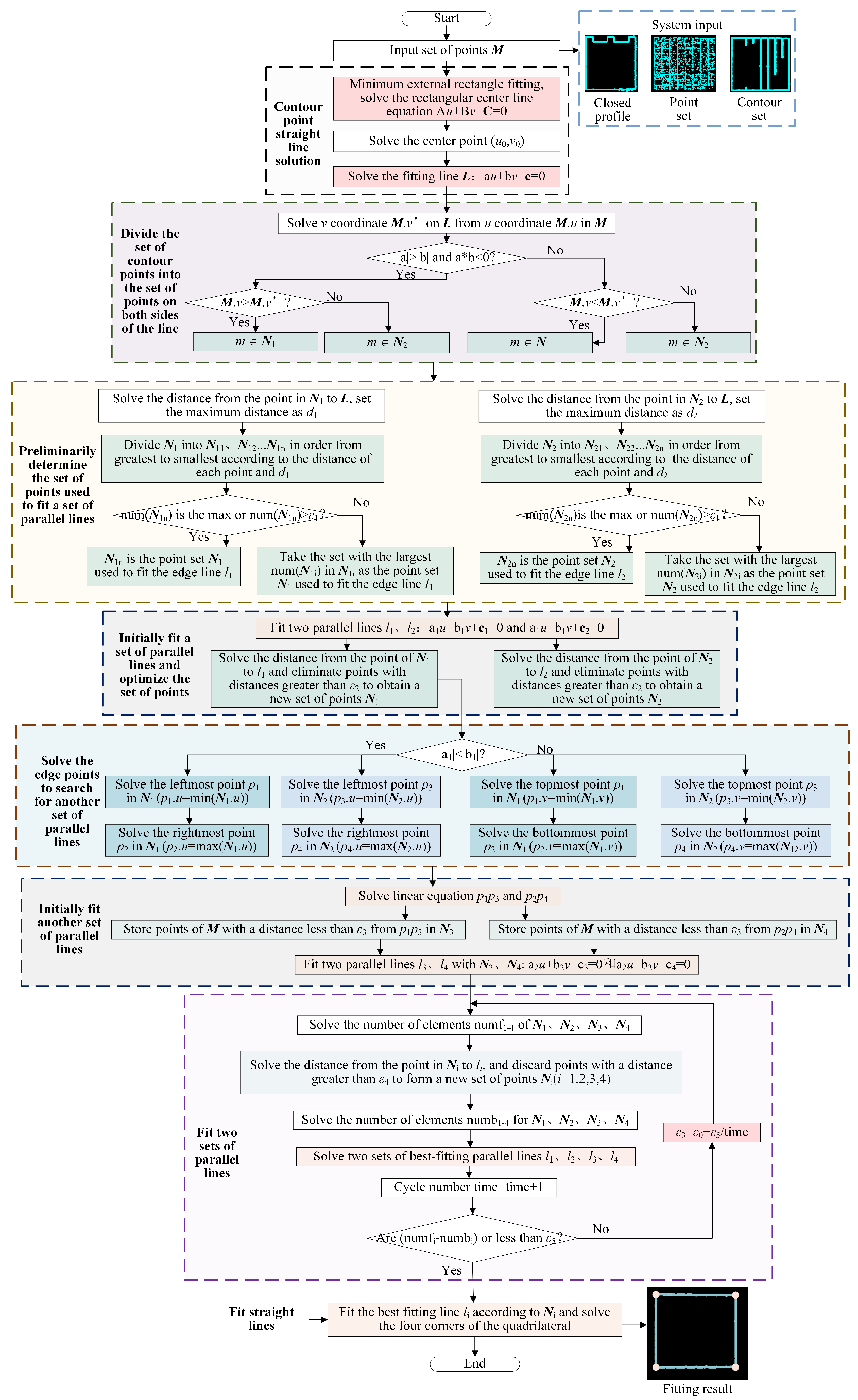
The comprehensive procedure of the parallelogram fitting algorithm, as proposed in this paper, is delineated in
Figure 5. The algorithm can be fed with input data in the form of a closed contour, a point set, or a set of contours. Here is a step-by-step breakdown of the algorithm: Step 1: Linear fitting of contour points, resulting in the centerline
of contour points based on the input point set. Step 2: Division of the point set into
and
on both sides of
to facilitate subsequent line fitting. Step 3: The point set for fitting parallel lines is selected and updated as
and
based on the distance between
and each point in these sets. Step 4: Use
and
to fit parallel lines
and
, updating
and
according to the distance between each point and the parallel lines. Step 5: Solve for the two groups of points at the edges of
and
. These two sets of points are interconnected to form a starting line for locating another set of points. Step 6: Preliminarily confirm the point set used to fit another group of parallel lines and subsequently fit those parallel lines. Step 7: Iteratively confirm the point sets used to fit the two groups of parallel lines and perform the fitting. Four sets of points and two sets of parallel lines are cyclically updated based on the distance between each point in the point sets and the lines. The distance threshold reduces as the iteration count increases to exclude points that significantly interfere with the parallel line fitting. When the elements of each point set no longer shrink after two iterations, the final point sets for fitting the four edges are derived. Step 8: To enhance the fitting precision, four lines are fitted separately using the four point sets. The intersection of these four lines yields the final fitting quadrilateral, with its four corners precisely determined. This algorithm provides a systematic approach for accurately fitting parallelograms, ensuring robust results for various input scenarios.
4.2. Line Fitting of Contour Points
In order to fit a line based on the input contour point set, it’s necessary to first calculate the coordinates of the contour’s center point. The coordinates of the center point
of the contour points
can be computed using the following formula:
fitted by contour points satisfies the following equation:
The distance between contour points and
are:
. To solve the center line
of the contour point is to solve
a,
b and
c, so that the minimum value of the following formula can be obtained:
Solve the above equation with the Lagrange multiplier method:
Simplified above formula:
It is obtained by solving for the eigenvalue:
4.3. Parallelogram Fitting
In the preceding section, we successfully fitted the centerline L. We then proceeded to segment the set of contour points into two distinct sets: one on each side of L. By considering the distance between each point and the centerline, we initially identified two point sets, and , which were earmarked for fitting a pair of parallel lines, and . Following this, we selected edge points from and and used them to determine two additional point sets, and , for fitting yet another pair of parallel lines within the parallelogram. These newly determined point sets, and , were then employed to initiate the fitting of another set of parallel lines, and .
4.3.1. Solving of the points sets on both sides of the center line
Firstly, the points in the contour point set are assigned to the point sets on both sides of the line according to their position relation with
L. Replace
in each point
m(
,
) in the contour point set with line
L:
to solve
. The relationship between each point in the contour point set and
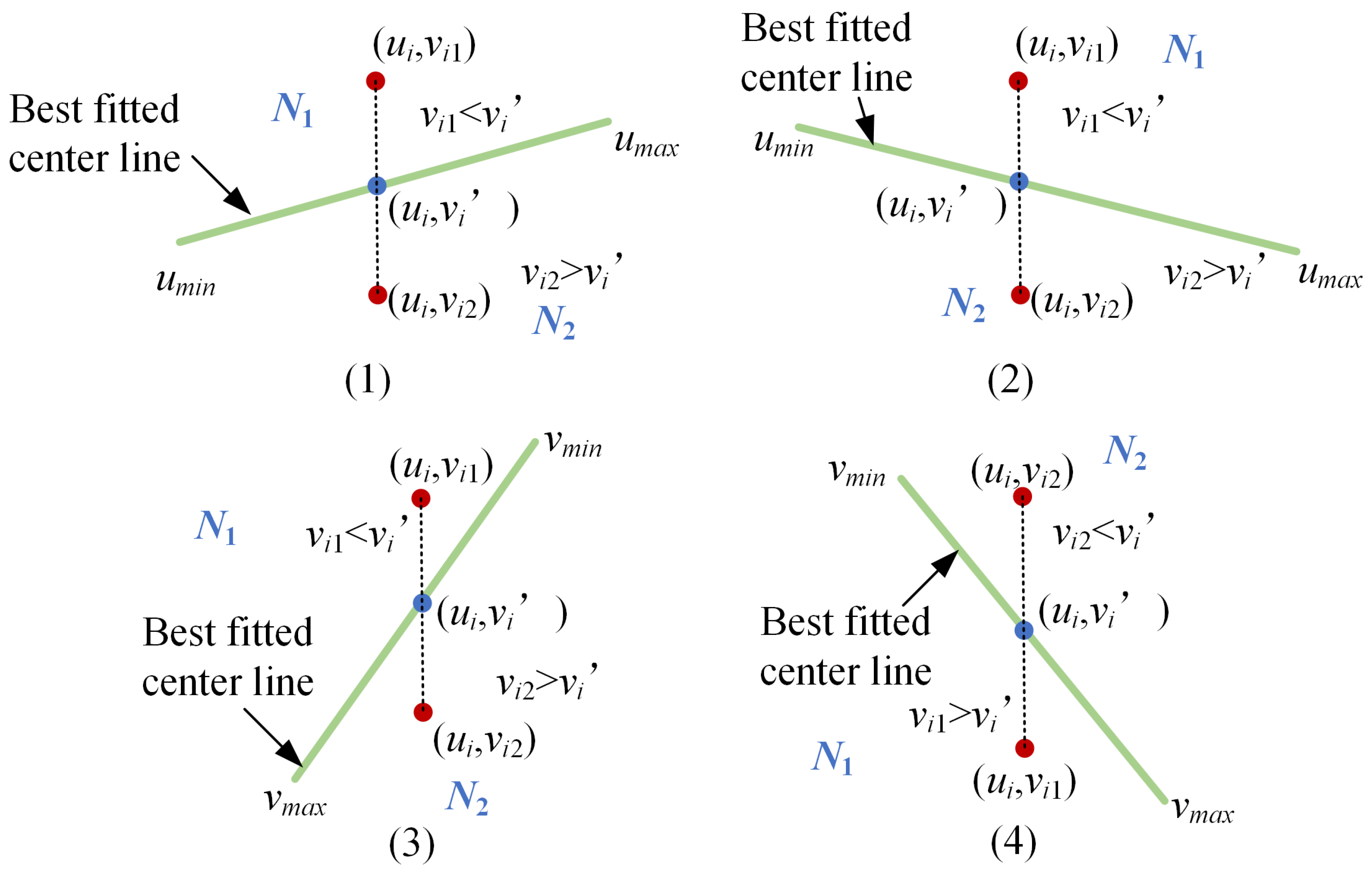
L can be summarized into the following four categories, as shown in
Figure 6. As shown in
Figure 6 (1) and (2), the slope of
L is
. If
<
,
, otherwise
. As shown in
Figure 6 (3), the slope of
L is
. If
<
,
, otherwise
. As shown in
Figure 5 (4), the slope of
L is
. If
>
,
, otherwise
.
4.3.2. Initially fitting of a set of parallel lines
A set of parallel lines are initially fitted with
and
. Solve the farthest distance
and
of the points in
and
to
with the follow formula:
Where, and are the number of elements of and .
We calculate the distances between the points in and with respect to the best fitting line L. These distances are classified based on their deviation from the values and . In theory, the set of edge points should be the farthest from L. Therefore, the set of points exhibiting the greatest deviation from the line should be used as the basis for fitting the parallel lines. However, if the number of elements in a point set is too small, it suggests that the set mainly comprises noise points. In such cases, we select the point set with the largest number of elements for fitting the parallel lines, which is then updated as and .
With
and
at hand, we proceed to fit a set of parallel lines. We utilize Equations (9) through (13) to fit the centerlines
and
for
and
, with respective slopes denoted as
and
. The inclination angles of these lines are represented by
and
, respectively.
To ensure that the slopes are equal, set the slope angle of parallel lines
. Then the
and
are:
Calculate the distance between points in and and the distance between points in and . The points whose distance is less than the threshold are retained and reconstructed into and .
4.3.3. Initially fitting another set of parallel lines
For fitting parallel lines, it is essential to partition the point set used for this purpose. Based on the
and
sets obtained in the previous section, we can determine a line using the edge points of the point set, and then search for the points near this line to form the set required for fitting parallel lines. The parallel lines,
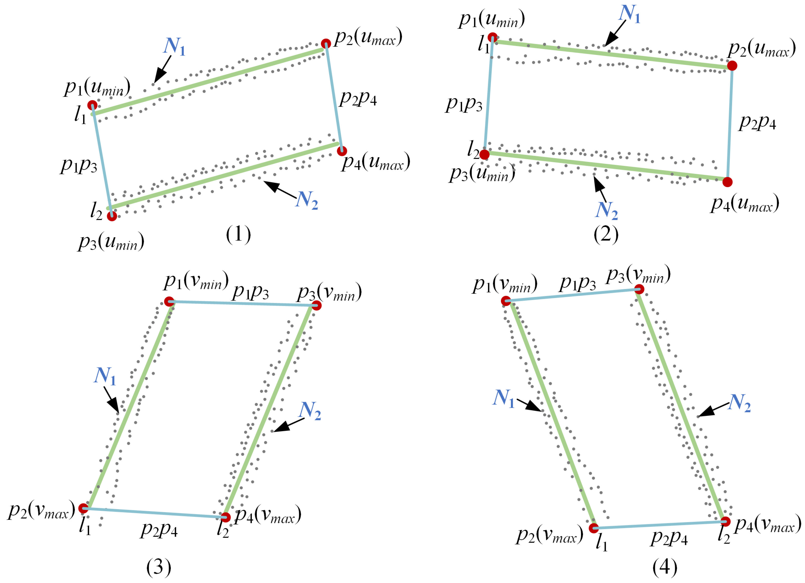
and
, fitted in the previous section exhibit four possible scenarios, as illustrated in
Figure 7.
When
, the target edge points are chosen based on the
u coordinates of points in
and
, as demonstrated in
Figure 7(1) and (2). The points in
and
with the smallest
u coordinates correspond to the leftmost points, denoted as
and
, while those with the largest
u coordinates correspond to the rightmost points, denoted as
and
. Conversely, when
, the selection of target edge points is based on the
v coordinates of points in
and
, as illustrated in
Figure 7(3) and (4). In this case, the points in
and
with the smallest
v coordinates represent the topmost points, designated as
and
, while those with the largest
v coordinates correspond to the bottommost points, denoted as
and
.
Connect
and
to form two lines. Take
as an example, its equation is:
To proceed, we calculate the distance between each point in the contour point set and the line segments and . Points whose distance is less than a predetermined threshold are selected to form the point sets and . Referring to equations (16) and (17), we then utilize and to initiate the fitting of another set of parallel lines, represented as , and represented as .
4.3.4. Parallelogram fitting
Following the steps described above, we have successfully obtained two sets of parallel lines, , , and , , along with four point sets (i = 1, 2, 3, 4). During the iterative process, points in that are beyond the threshold distance from are iteratively removed, and is re-fitted after each update of point set . The distance threshold between points and the parallel lines decreases with each iteration. When, in both cycles, the number of elements in falls below the threshold, it indicates that each point set has essentially reached its optimal configuration, and the iterative process is terminated.
Rectangles in Cartesian space only approximate parallelograms in the image plane. To further enhance the fitting accuracy, we use equations (9) through (13) to fit their optimal fitting lines,
, respectively. At this point,
and
, as well as
and
, need not remain parallel. These four lines intersect to form the final fitted quadrilateral. We employ the following formula to calculate the
u and
v coordinates of the four corners of the quadrilateral:
5. Pose Solution Method of Non-Cooperative Target
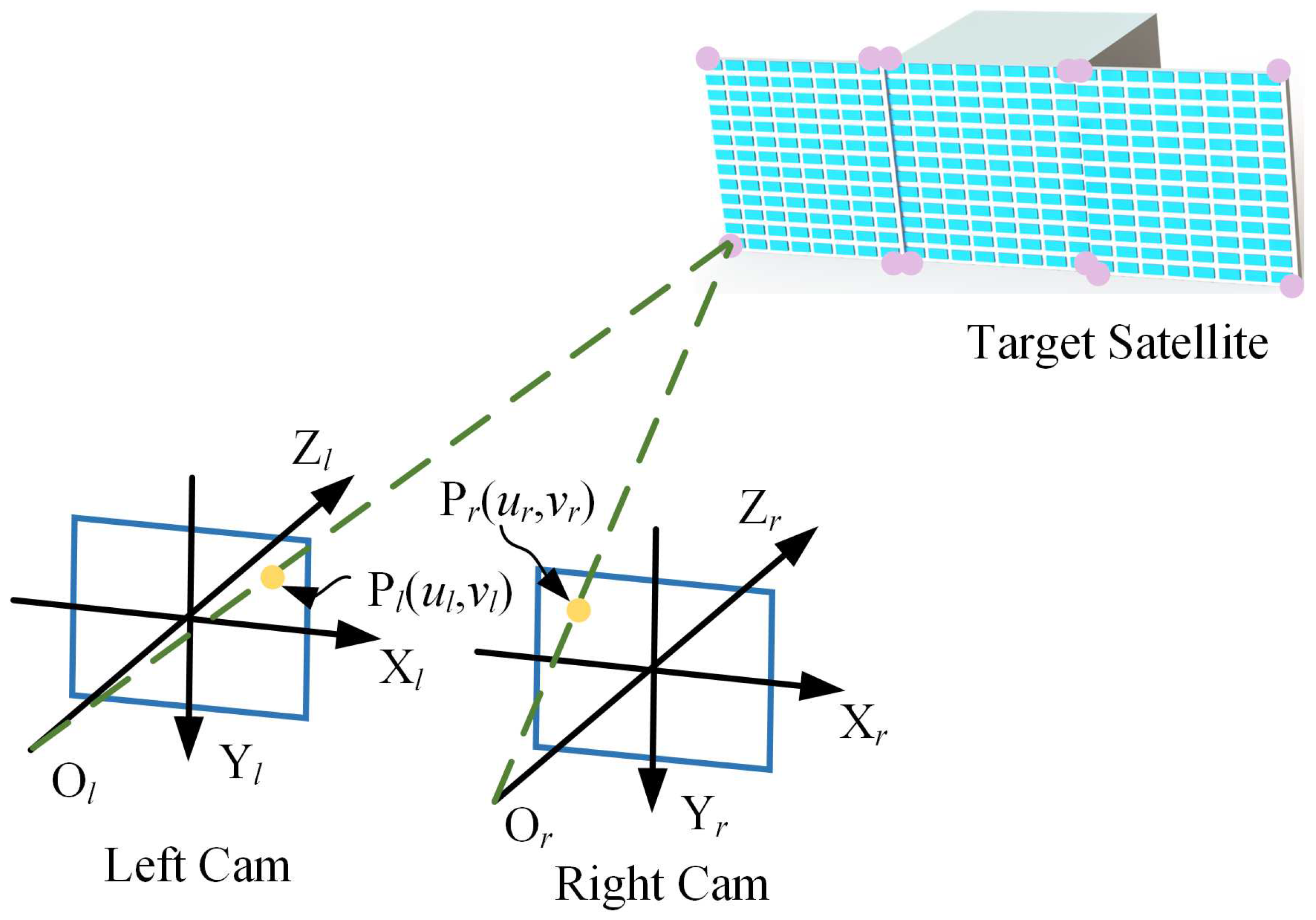
As shown in
Figure 8, stereo vision is used to detect the corner points of the satellite. The coordinates of the satellite solar panel corners extracted by the left and right cameras in the pixel plane are respectively
(
i = 1, 2...12).
The left camera coordinate system is the world coordinate system. The position
of each corner point of the satellite solar panel is [
29]:
where.
and represent the transformation matrix parameters that relate the pixel plane coordinate system to the world coordinate system for the left and right cameras, respectively. To enhance the accuracy of stereo vision measurements, a procedure involving plane fitting to the detected solar panel corners is conducted, where the projected corner points onto the fitted plane serve as the corrected corner points. The specific steps are as follows:
The least square method is used to fit the solar panel plane. In the left camera coordinate system, the depth information
of each corner point is greater than 0, and the fitting plane will not be parallel to the Z-axis of the left camera coordinate system (Because in parallel, the solar panel is a line in the image and cannot be measured). Therefore, the plane equation
can be set as:
. For the fitted plane, the sum of distances from each point to the plane is minimum, that is:
The equation of the plane
M is:
The projection coordinates
of each corner point of the satellite on the plane
M are:
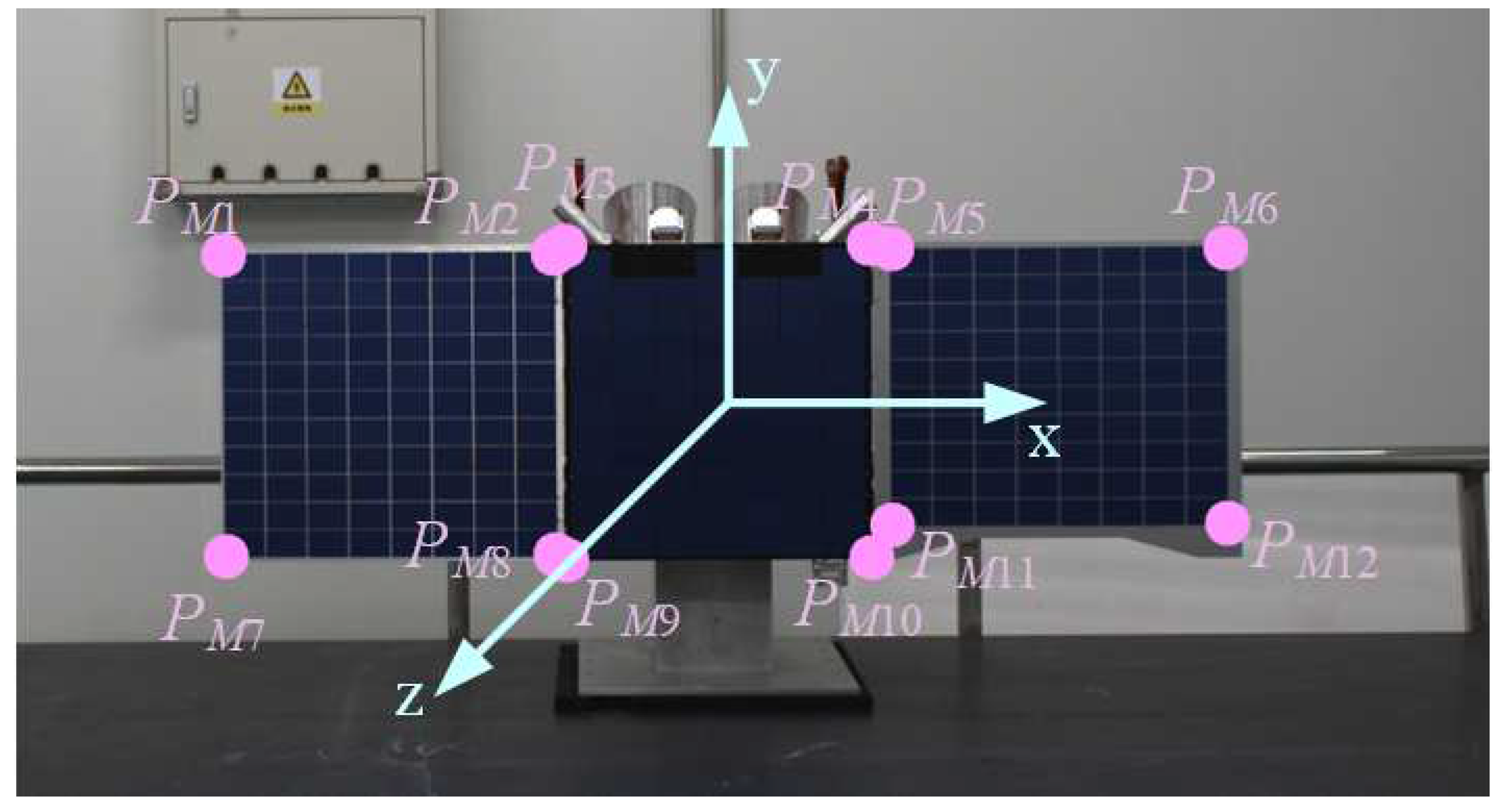
As shown in
Figure 9, with the center of the solar panel as the origin of the coordinate system, the translation matrix of the solar panel relative to the camera coordinate system is
. The solar panel coordinate system Z-axis in the camera coordinate system is:
. The X-axis in the camera coordinate system is:
So the Y-axis in the camera coordinate system is:
6. Experimental Verification
6.1. Satellite Natural Feature Recognition Experiment
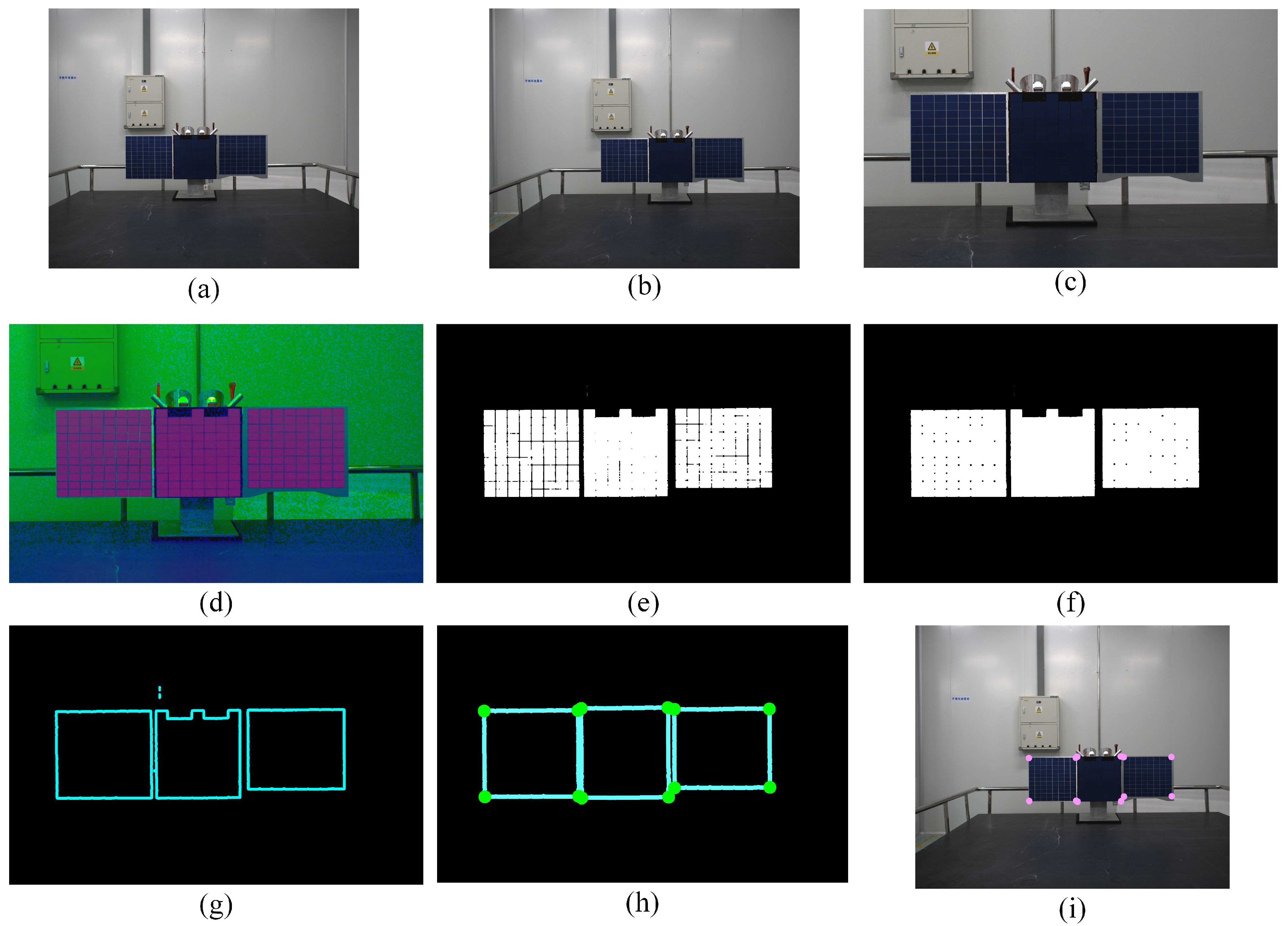
To evaluate the success rate and the calculation speed of the satellite detection algorithm proposed in this paper, 100 times of tests which the distance and attitude between stereo vision and satellite varied a lot were conducted. The experimental system operated on a PC equipped with an Intel(R) i5-8500 CPU (3.0GHz) and 8.0GB of RAM. As an example, considering a monocular camera, the processing results of each step are illustrated in
Figure 10. These steps successfully eliminate interference contours and points inside and outside the solar panel, while accurately extracting edge and corner points of the solar panel.
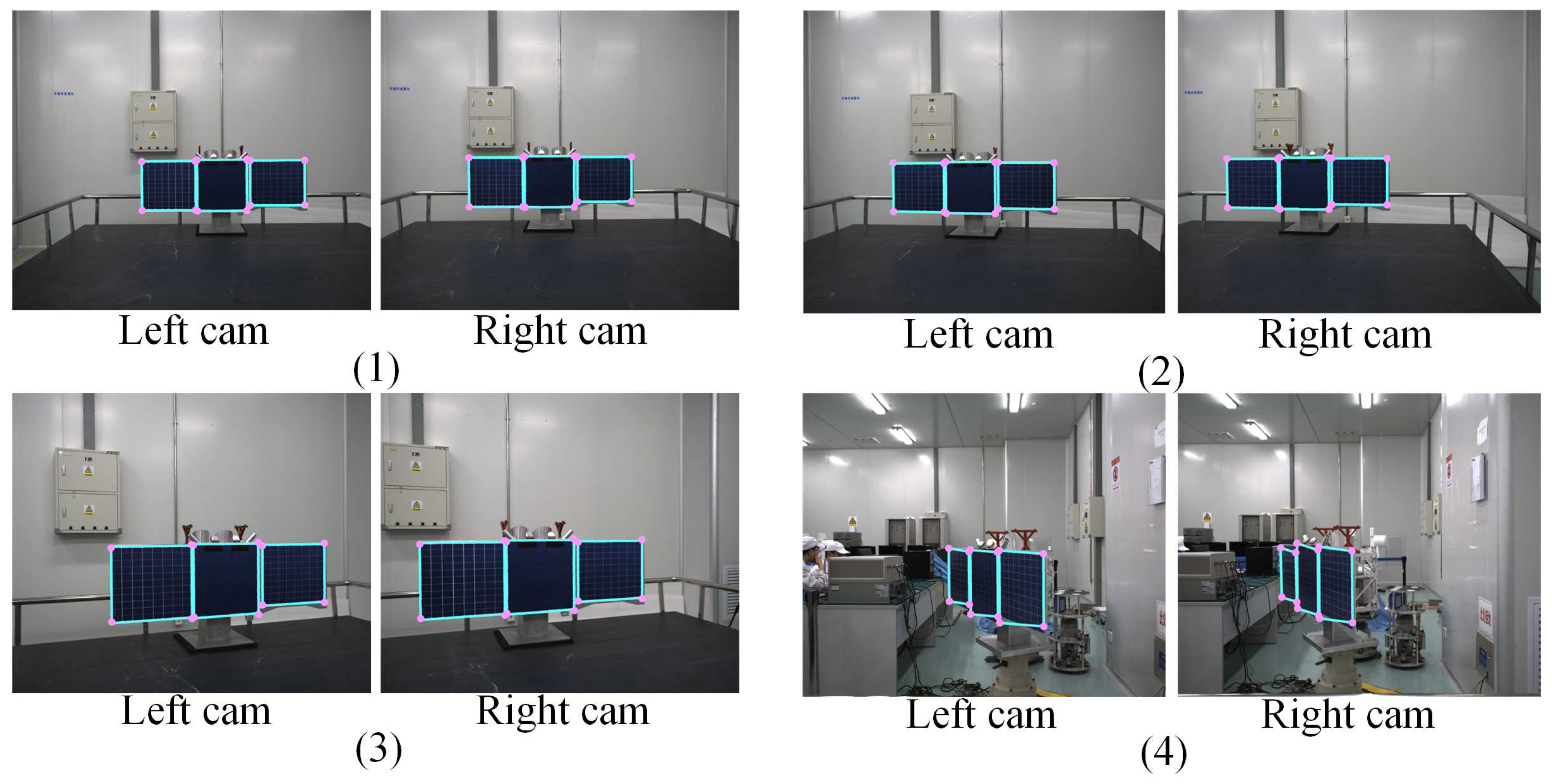
Figure 11 displays typical recognition results from these tests. It is evident that across different observation distances and angles, the algorithm presented in this paper consistently and accurately extracts the corners and contours of the satellite’s solar panels. The experiments resulted in a remarkable 98.5% success rate in satellite detection, with an average detection time of only 0.14 seconds. Instances of detection failure were primarily attributed to scenarios where the solar panel plane was nearly parallel to the camera’s optical axis, causing the solar panel to appear as a line in the image.
6.2. Measurement Accuracy Test of Satellite Pose
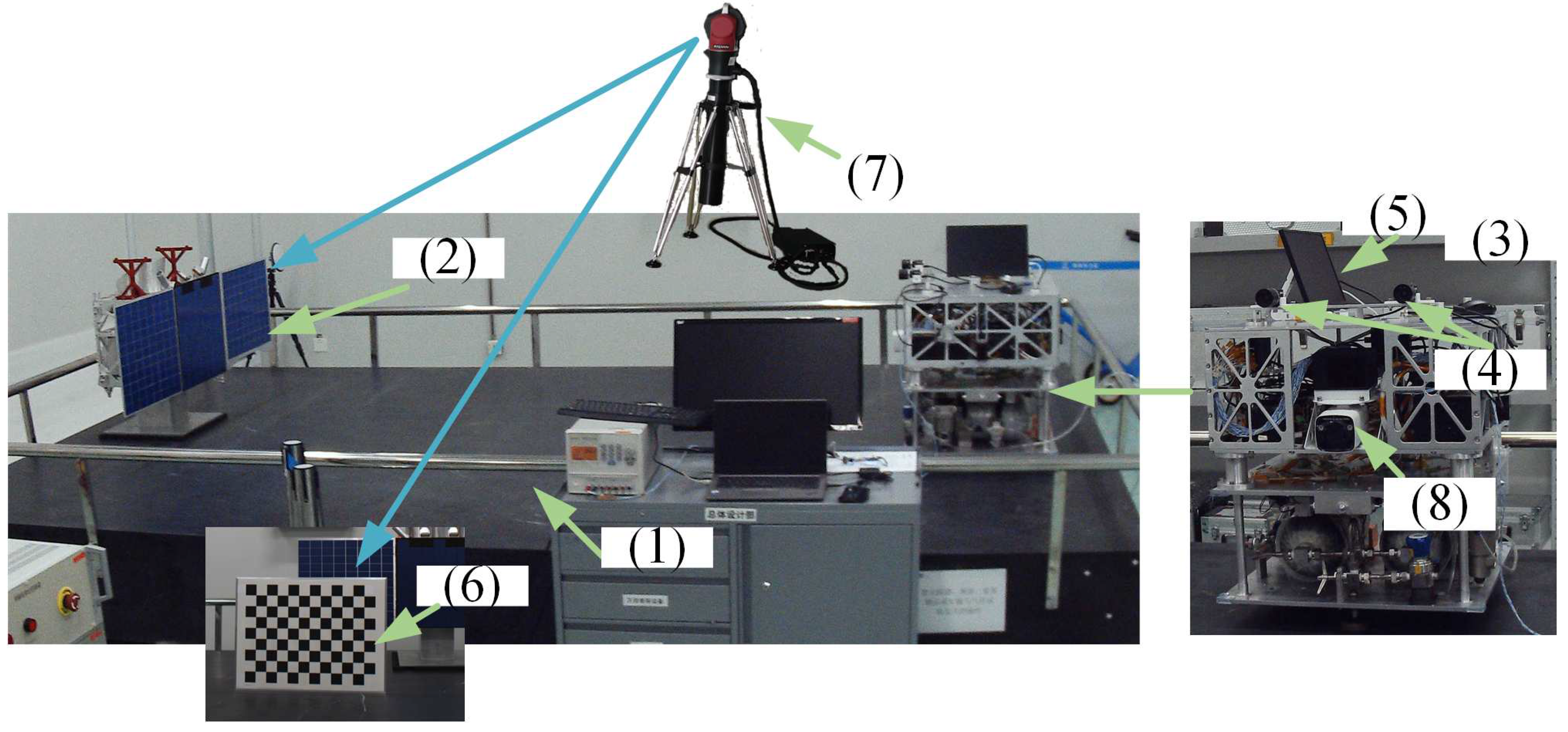
To assess the measurement accuracy of the algorithm proposed in this paper for determining the satellite’s pose, we established an experimental platform, as depicted in
Figure 12. This platform featured air feet beneath both the target satellite and the service satellite, enabling them to move freely on the air platform. A stereo vision system was mounted on the service satellite, capturing images and transmitting them to a central controller that executed the algorithm presented in this paper. To ensure precise measurements, a laser tracker and calibration board were employed to calibrate the relative pose between the stereo vision system and the laser tracker, as well as to measure the pose between the satellite and the camera. The satellite’s poses were measured using stereo vision. These measurements were then compared with the data obtained from the laser tracker to evaluate the measurement accuracy of the algorithm proposed in this paper. The service satellite was equipped with an LIDAR, which can synchronously measure the relative position between the target satellite and the service satellite.
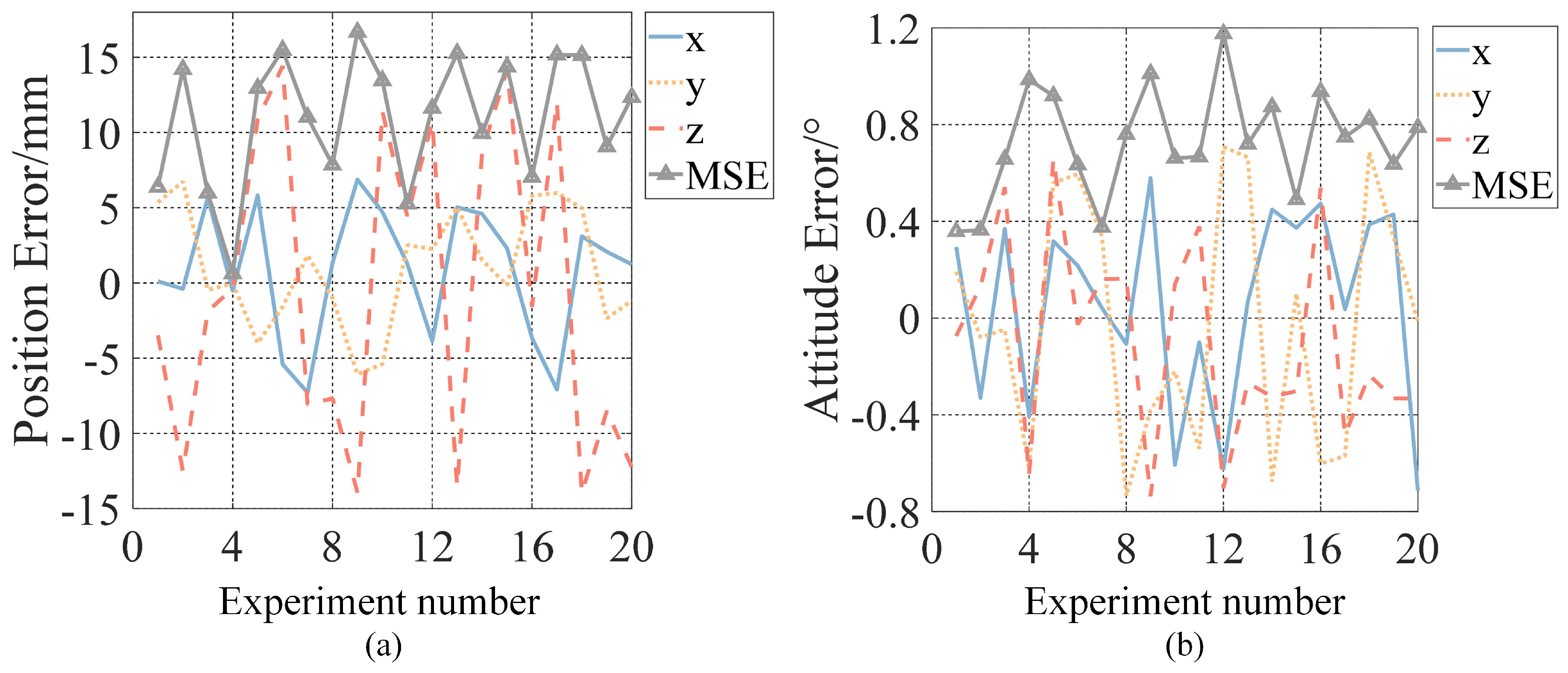
A comprehensive set of 20 experiments was conducted, and the resulting pose measurement errors are depicted in
Figure 13.
Figure 13(a) provides insight into the position measurement errors and the root mean square (MSE) of the position errors in the x, y, and z directions of the satellite, while
Figure 13(b) displays the attitude measurement errors and the root mean square of the attitude errors in the x, y, and z directions of the satellite. The results indicate that the measurements of pose errors remain consistently stable. The position measurement errors in the x and y directions are less than 7mm, while the position measurement error in the z direction is less than 12mm. Furthermore, the three-dimensional attitude errors are all under 1.2°, demonstrating a high level of accuracy in attitude measurement. The average measurement errors for satellite pose are summarized in
Table 1, where the average position measurement error is 10.412mm and the average attitude measurement error is 0.661°. These results underscore the precision and reliability of the proposed algorithm for satellite pose measurement.
The performance of various non-cooperative spacecraft detection methods can be evaluated through experimental testing and existing literature data. The detection results are shown in
Table 2. In order to measure the detection success rate and detection speed of various methods, 100 experiments were carried out. As for this paper’s method, the successful rate of satellite detection was 98.5%, with an average detection time of only 0.14 seconds. In comparison to existing methods, including stereo vision-based outer rectangle detection, edge line detection, and LiDAR-based detection, the proposed method stands out. The success rate of stereo vision-based detection for solar panel edge was notably lower at only 67%. This reduced success rate can be attributed to the presence of numerous straight-line features in the image due to the solar panel’s composition of small rectangles, making it challenging to extract the target straight lines accurately. Overall, the method presented in this paper demonstrates superior performance in terms of speed and successful rate, surpassing all other methods except the stereo vision-based outer rectangle detection in the image plane, making it a compelling choice for satellite detection applications. As for the method of detecting satellites with deep learning in [
20], the success rate was 96%. Because the algorithms are equipped with different hardware, the running time of the algorithms was not compared. Twenty experiments were carried out to test the measurement accuracy of various algorithms from different relative distance and relative attitude measurements of satellites. The test results show that the proposed method is highly accurate. External rectangle detection methods exhibit generally low accuracy, with fitting errors increasing as the deflection angle of the rectangular feature grows. Given the presence of numerous linear features on satellites, these features can significantly interfere with the extraction of the target line, resulting in a poor success rate and low accuracy in satellite edge line detection. LiDAR, for example, installed in this experimental system shown inaa
Figure 12, typically achieves a detection accuracy of approximately 30mm, primarily capable of determining the target’s position. However, it often struggles with determining the attitude of the target and often necessitates the cooperation of visual sensors for this purpose. Methods like deep learning require substantial prior information about satellites, making them costly in terms of resource requirements. Compared with [
24]’s method of detecting satellite pose with stereo vision, the detection accuracy of this paper is also significantly higher. In contrast, the parallelogram fitting method for rectangular features of non-cooperative spacecraft in the image plane, as proposed in this paper, exhibits exceptional performance. It excels in terms of detection accuracy, speed, and algorithm robustness, making it a promising choice for non-cooperative spacecraft feature detection, especially when other methods face limitations.
7. Conclusion
This paper introduces a novel method for recognizing rectangular natural features and measuring the pose of non-cooperative spacecraft, addressing the challenging task of detecting the poses of such spacecraft in space. The method is applicable to various objects on the spacecraft, including the spacecraft body and solar panels. It employs a parallelogram fitting approach for detecting non-cooperative targets and measuring their poses. Image features are extracted using stereo vision, and the projection of rectangular features onto the image plane is then detected and fitted into parallelograms. An experimental system was established to conduct pose measurement experiments at different distances. The proposed algorithm achieved an average position measurement error of 10.412mm and an average attitude measurement error of 0.661°. These results demonstrate the method’s suitability for applications of in-orbit close-range target measurement. This paper’s method offers valuable insights and reference points for the development of spatial object detection algorithms and the recognition of rectangular features in Cartesian space across various working scenarios. Future research will focus on satellite detection under different illumination conditions and visual servo control.
Author Contributions
Conceptualization, F.W. and L.Y.; methodology, F.W. and L.Y.; resources,W.X.; writing—original draft, F.W.; validation, W.P.; funding acquisition, C.X. All authors have read and agreed to the published version of the manuscript.
Funding
This research was funded by the National Natural Science Foundation of China (62203140), Shenzhen Peacock Team Fundation (KQTD20210811090146075), Shenzhen Outstanding youth basic research (RCJC20200714114436040), the National Natural Science Foundation of China (11802073) and Shenzhen Science and Technology Innovation Commission (JSGG20191129145212206).
Institutional Review Board Statement
Not applicable.
Informed Consent Statement
Not applicable.
Data Availability Statement
Not applicable.
Acknowledgments
Not applicable.
Conflicts of Interest
The authors declare no conflict of interest.
Sample Availability
Not applicable.
References
- Zhi, X.; Yao, X.S.; Yu, F. Position and attitude joint determination for failed satellite in space close-distance approach. J Nanjing Univ Aeronaut Astronaut 2013, 45, 583–589. [Google Scholar]
- Flores-Abad, A.; Ma, O.; Pham, K. A review of space robotics technologies for on-orbit servicing. Progress in aerospace sciences 2014, 68, 1–26. [Google Scholar] [CrossRef]
- Shan, M.; Guo, J.; Gill, E. Review and comparison of active space debris capturing and removal methods. Progress in aerospace sciences 2016, 80, 18–32. [Google Scholar] [CrossRef]
- Zhao, Y.; Zhang, F.; Huang, P. Impulsive super-twisting sliding mode control for space debris capturing via tethered space net robot. IEEE Transactions on Industrial Electronics 2019, 67, 6874–6882. [Google Scholar] [CrossRef]
- Huang, P.; Zhang, F.; Cai, J. PDexterous tethered space robot: Design, measurement, control, and experiment. IEEE Transactions on Aerospace and Electronic Systems 2017, 53, 1452–1468. [Google Scholar] [CrossRef]
- Segal, S.; Carmi, A.; Gurfil, P. Stereovision-based estimation of relative dynamics between noncooperative satellites: Theory and experiments. IEEE Transactions on Control Systems Technology 2013, 22, 568–584. [Google Scholar] [CrossRef]
- Rybus, T. Obstacle avoidance in space robotics: Review of major challenges and proposed solutions. Progress in Aerospace Sciences 2018, 101, 31–48. [Google Scholar] [CrossRef]
- Li Y; Bo Y; Zhao G. Survey of measurement of position and pose for space non-cooperative target. In Proceedings of 2015 34th Chinese Control Conference, Hangzhou,China, 2015, pp.528-536.
- Franzese, V.; Hein, A.M. Modelling Detection Distances to Small Bodies Using Spacecraft Cameras. Modelling 2023, 4(4), 600–610. [Google Scholar] [CrossRef]
- Attzs, M.N.J.; Mahendrakar, T.; Mahendrakar, T. Comparison of Tracking-By-Detection Algorithms for Real-Time Satellite Component Tracking. Computers and Electronics in Agriculture 2023. [Google Scholar]
- C. English; G. Okouneva; P. Saint-Cyr. Real-time dynamic pose estimation systems in space lessons learned for system design and performance evaluation. Int. J. Intell. Control Syst. 2011, 16(2), 79–96.
- P. Huang; F. Zhang; J. Cai. Dexterous tethered space robot: Design, measurement, control, and experiment. IEEE Trans. Aerosp. Electron. Syst. 2017, 53(3), 1452––1468. [CrossRef]
- L. Liu; G. Zhao; Y. Bo. Point Cloud Based Relative Pose Estimation of a Satellite in Close Range. Sensors 2016, 16(6), 824––841. [CrossRef]
- T. Tzschichholz; T. Boge; K. Schilling. Relative Pose Estimation of Satellites Using PMD-/ccd-sensor Data Fusion. Acta Astronautica 2015, 109, 25––33. [CrossRef]
- K. Klionovska; H. Benninghoff. Initial Pose Estimation Using PMD Sensor During the Rendezvous Phase in On-orbit Servicing Missions. In 27th AAS/AIAA Space Flight Mechanics Meeting, San Antonio,USA, 2017, pp.263-279.
- X. Gao; K. Xu; H. Zhang. Position-pose measurement algorithm based on single camera and laser range-finder. J. Sci. Instrum 2007, 28(8), 1479––1485.
- Duan F; E. H; Bernelli Zazzera F. Observer-Based Fault-Tolerant Integrated Orbit-Attitude Control of Solarsail. In INTERNATIONAL ASTRONAUTICAL CONGRESS: IAC PROCEEDINGS, 2023, pp.1-7.
- Kilduff T; Machuca P; Rosengren A J. Crater Detection for Cislunar Autonomous Navigation through Convolutional Neural Networks. In AAS/AIAA Astrodynamics Specialist Conference, 2023, pp.1-12.
- Mei, Y.; Liao, Y.; Gong, K. SE (3)-based Finite-time Fault-tolerant Control of Spacecraft Integrated Attitude-orbit. Journal of System Simulation 2023, 35, 277–285. [Google Scholar] [CrossRef]
- Kobayashi D; Burton A; Frueh C. AI-Assisted Near-Field Monocular Monostatic Pose Estimation of Spacecraft. In The Advanced Maui Optical and Space Surveillance Technologies (AMOS) Conference, 2023.
- Sharma S;Beierle C; D’Amico S. Pose estimation for non-cooperative spacecraft rendezvous using convolutional neural networks. In Proceedings of 2018 IEEE Aerospace Conference, 2018; pp.1-12.
- Peng, J.; Xu, W.; Liang, B. Pose measurement and motion estimation of space non-cooperative targets based on laser radar and stereo-vision fusion. IEEE Sensors Journal 2018, 19, 3008–3019. [Google Scholar] [CrossRef]
- Jianqing P; Wenfu X. A Pose Measurement Method of a Space Noncooperative Target Based on Maximum Outer Contour Recognition. IEEE Transactions on Aerospace and Electronic Systems 2019, 56(1), 512–526. [CrossRef]
- Peng, J.; Xu, W.; Liang, B. Virtual Stereo-vision Pose Measurement of Non-cooperative Space Targets for a Dual-arm Space Robot. IEEE Transactions on Instrumentation & Measurement 2019, 32, 1–13. [Google Scholar]
- Yu, F.; He, Z.; Qiao, B. Stereo-vision-based relative pose estimation for the rendezvous and docking of noncooperative satellites. Mathematical Problems in Engineering 2014, 21, 1–12. [Google Scholar] [CrossRef]
- Chaudhuri, D.; Samal, A.; Yu, F. A simple method for fitting of bounding rectangle to closed regions. Pattern Recognition 2007, 40(7), 1981–1989. [Google Scholar] [CrossRef]
- Chaudhuri, D.; Kushwaha, N.K.; Sharif, I. Finding best-fitted rectangle for regions using a bisection method. Machine Vision and Applications 2011, 23, 1263–1271. [Google Scholar] [CrossRef]
- Yang J; Jiang Z. Rectangle fitting via quadratic programming. In Proceedings of 2015 IEEE 17th International Workshop on Multimedia Signal Processing (MMSP), 2015.
- Ayache, N. Rectification of images for binocular and trinocular stereovision. In Proceedings of the International Conference on Pattern Recognition, Rome, Italy, 14-17 November 1988; pp. 348–379. [Google Scholar]
|
Disclaimer/Publisher’s Note: The statements, opinions and data contained in all publications are solely those of the individual author(s) and contributor(s) and not of MDPI and/or the editor(s). MDPI and/or the editor(s) disclaim responsibility for any injury to people or property resulting from any ideas, methods, instructions or products referred to in the content. |
© 2024 by the authors. Licensee MDPI, Basel, Switzerland. This article is an open access article distributed under the terms and conditions of the Creative Commons Attribution (CC BY) license (http://creativecommons.org/licenses/by/4.0/).

