
Submitted:
26 December 2023
Posted:
29 December 2023
You are already at the latest version
Abstract
The valve controlled cylinder drive system is the most common type among hydraulic applications. The nonlinear behaviour in such system is inevitable when the valve spool around its null position [1] , Leaney [2] utilised component linking method to investigate the nonlinearities in a Moog valve controlled asymmetric cylinder drive system by simulation in Fortran, in which a generalised concept is introduced and validated by comparing to the experimental results. An factor is proposed in the generalised concepts to describe the asymmetric cylinder state, which is a constant when the cylinder in extending or retracting, but numerically calculated when the valve spool in the underlap region [2]. This paper utilises the component linking method to simulate the Moog valve controlled asymmetric cylinder drive system in Matlab Simulink, and proposed an analytical solution for factor when the valve spool in the underlap region.
Keywords:
Moog
; asymmetric cylinder
; analytical solution
; component linking
; X-factor
1. Introduction
Hydraulic power systems [3] are widely used in industrial manufacture, building construction, port transportation, funfair, etc. They use fluid to achieve energy transmission without a rigid joint. Hydraulic power is able to produce massive force and torque within a compact and lighter package, and the conventional rigid components like gears and joints can be avoided.
Hydraulic linear actuators are mainly symmetric cylinder or asymmetric cylinder. The symmetric cylinder has equal piston area and the asymmetric type (also named as single rod) cylinder comes with different piston areas. The symmetric cylinder is usually utilised for high-performance requirements, due to its linear performance with symmetric ported control valve. This type of cylinder is widely applied in aerospace and military for high performance and dynamic response [4]. However, the asymmetric cylinder [5] drive occupies 80% of the hydraulic applications [6], such as cranes, injection moulding systems, and hydraulic press machines, etc. The asymmetric cylinder drive is usually controlled by a symmetric ported valve, unequal flow rate will be delivered into cylinder chambers with same valve opening in the extending or retracting state, which means system parameters do not remain the same after the valve crosses its null position [7]. Leaney [8] did research in these nonlinearities, but how the system performs when the valve in the underlap region is not explicitly explained. Viersma [1] indicates that pressure jumps will occur when the valve spool is around its null position, causing ‘implosion’ or ‘explosion’ of oil owing to its compressibility, so that smooth operation around valve null position is impossible.
A test rig of a four-way servovalve controlled asymmetric cylinder hydraulic system is constructed by Leaney [2], the system is a typical symmetric ported valve controlled asymmetric cylinder system, which is depicted in Figure 1, the Moog series 76 model 102 four-way valve is used to control the asymmetric cylinder system to achieve the desired output.
Leaney [8] simulated his test rig with ‘Component Linking’ method, which models each of the components such as valve, actuator/cylinder and load, then combines them to perform the whole system simulation. This method aims at simplifying the ‘Small Perturbation’ model [9], which utilised a single transfer function to describe a whole hydraulic system. However, as not all parameters of a hydraulic system remain constant during operation and a single transfer function is mainly designed for a linear time-invariant (LTI) system, a single transfer function [10] is difficult to capture the behaviours of a hydraulic system. Modelling the components separately is easier for the analysis and adjusting of the system parameters.
The components of the asymmetric cylinder system are connected by the concept of ‘power bonding’, in other words, the components are connected by the power transfer, such concept is still utilised nowadays for a hydraulic system of the 50 wheel loader [11]. In Leaney’s paper [2], three components are the major concerns, which are valve, actuator and load model. Their power transfers are indicated in Figure 2, the voltage is input to the valve model to control the valve opening, the flow passes through the valve and drops to a certain value. Pressure and flow are delivered to the actuator model, which outputs the force/torque and velocity. Finally, the load model outputs the velocity and force.
1.1. Valve model
The control valve (electrohydraulic valve) is a Moog 76 model 102 flow control four-way servovalve, its schematic diagram is depicted in Figure 3. If current is applied in the armature coil in the torque motor, the T-shape flapper rotates slightly. Assuming the flapper rotates clockwise, the offset between the left nozzle and flapper decreases, which leads to the decrease of flow passing through the left nozzle and causes the pressure increasing in the left control line. A similar process occurs in the right control line, leading to a decrease of pressure.
The pressure difference in the control line moves the spool, therefore bends the feedback spring to balance the torque generated by the torque motor, so that the spool displacement is dependent on the rotation of the torque motor; furthermore, the spool displacement is dependent on the current.
Appropriate transfer functions, equations 1 and 2, are given by Moog [13]. The expressions are linear, empirical relationships that approximate the responses of the actual servovalve. For the frequency range below 50 Hz, the valve dynamic can be approximated by a first-order transfer function below [13]:
where is the flow gain and is the servovalve time constant .
A second-order transfer function is necessary to represent wider frequency range response as given below [13]:
where is the natural frequency [], and is the damping ratio. In a limit cycle oscillation study of a low-frequency phenomenon, a higher order valve model does not have significant difference compared to a lower order model [14]. Hisa [15] stated that a reduced order transfer function can be used to approximate a higher order transfer function, and a first order model is used as a reference model by Persson et al [16].
As all of the valve operational frequencies in this research are much lower than 50 Hz, the first order transfer function equation 1 is chosen for the valve model. As the displacement of the spool, , controls the flow rate of the valve, equation 1 can be modified as:
where is the gain of the system [].
The current is generated by an amplifier. Assuming the amplifier is ideal, then current is proportional to the input voltage as given by equation 4:
where is the gain of voltage to current []. Hence the valve dynamics are represented by:
A block diagram for this valve model is depicted in Figure 4.
1.2. Flow gain
The flow gain is the gain that depicts the relationship between the valve opening and the oil flow across it. In order to interpret it clearly, a physical layout of the four-way valve-controlled [17] asymmetric cylinder is listed in Figure 5:
is the flow rate that delivered into the piston side chamber, is the volume of fluid that trapped in the piston chamber, is the piston side area of the cylinder, the subscript 2 indicates corresponding parameters in rod side chamber. is the supply pressure, is the return line pressure of oil tank, which is zero. is the opening area of the corresponding port of the valve, subscripts 1, 2, 3 and 4 indicate different ports of the valve which are depicted in Figure 5. is the cylinder displacement. is the flow pass through the port, is the flow pass through port, is the flow pass through the port and is the flow pass though the port.
The flow deliver into the chambers can be described as:
For a symmetric ported valve, and , so that equations 6 and 7 can be simplified as:
These two equations can be applied when the valve is in the extending, retracting and underlap region, the underlap region is the valve spool position where all ports opening areas are non-zero. Even for a zerolapped valve, due to the manufacture tolerance [18] , there will be a small underlap when the spool is placed in the null position. Figure 6 depicts the theoretical and actual situation for a nominally zero lapped valve.
The manufacture tolerances can be identified as:
i Radial clearance between spool and sleeve
ii Tolerance on lap
1.3. The actuator model
The actuator model connects the valve and load model, which accepts the information of flow and pressure as input, then output force to the load model. The types of hydraulic actuators are mainly symmetric cylinder, asymmetric cylinder and hydraulic motor. Due to the target of this research, the asymmetric cylinder is the only one under analysis.
No matter the asymmetric cylinder in the extending or retracting state, the flow in its chamber consists of input flow, displacement flow and compressibility flow. But under different operational states, the flow balance equations in different chambers are not the same.
For the cylinder extending state:
For the cylinder retracting state:
where
is the area of cylinder piston side area or rod side area [], is the cylinder velocity [], is the cylinder chamber volume [], is the cylinder chamber pressure [] and is the fluid Bulking Modulus []. The subscript and indicate the piston side chamber and rod side chamber respectively.
A generalised definition of these equations is proposed by Leaney [2], which uses effective parameters to describe the system behaviours rather analyse them separately in different cylinder chambers. The generalised equations are depicted as:
Substitute these effective parameters into the flow and pressure equations reveals:
For cylinder retracting (>0 and =0), the service line pressures can be rewritten as [2]:
where is the area ratio of the cylinder, Leaney [2] introduced factor to unify the expression for , and utilised the generalised concepts in the component linking method. The factor value depends on the region of the spool operation, =1 for cylinder extending state and = for cylinder retracting state. And the service line pressure and can be written as:
where is the area ratio and is effective total volume [].
The factor value is known and clear when the valve is outside the underlap region. However, when the valve spool is in the underlap region, the value is difficult to be found explicitly and it can be numerically solved by an implicit equation 25 [2] as below:
Now the effective load flow can be revealed [2]:
The actuator model block diagram is depicted in Figure 8.
1.4. The load model
The load model is various based on different test rig set up, in order to simplify the analysis afterwards, the load set up is a simple asymmetric cylinder coupling with a load, which is placed on a surface, So that the load force balance can be depicted by:
where is the load mass [] and is the acceleration [].
2. Materials and Methods
Leaney [2] stated that the cylinder chamber pressures and must be numerically solved when the valve in the underlap region, due to the derived implicit equation 25. The chamber pressures are the power source to drive the cylinder, so that the system behaviours are decided by chamber pressures. How the pressures perform when the valve is outside the underlap region is explicit. The chamber pressures behaviours in underlap region are solved numerically as shown in Figure 10.
An input signal is set to drive the valve moving across the underlap region in a small-time interval with a constant speed. The supply pressure is 70 bar and all the modelling parameters are the same as those in Moog valve controlled asymmetric cylinder system in the last section.
As the chamber pressures of the asymmetric cylinder when the valve in the underlap region is modelled and they are numerically solved. The key part is the factor equation 25 from [2]. The solving command in Matlab is fsolve and it uses the rust-region algorithm [14] to find the root of factor with given valve opening areas , and area ratio . Numerically solving equation 25 takes a lot of computing time, if the value can be analytical solved, simulation time cost can be massively reduced. A trial is given in the rest of this section.
Square both sides of equation 25 leads to:
Rearrange it:
Let be given as:
Let be given as:
Substitute and into equation 31 reveals:
Square both sides of equation 32 leads to:
Rearrange the equation 33 reveals:
Let
Equation 34 becomes:
Square both side of the equation 36, reveals:
Rearrange above equation reveals:
Let
Thus equation 38 becomes:
Let
As a result, equation 40 becomes:
The value of factor is a problem of find the root of a quartic equation 42. A general form of roots can be depicted as below equations 43:
where
where
Actually, there is only one value of factor with a set of parameters. However, there are four roots from a quartic equation and the value of is one of them.
To identify the correct root, the method is depicted as following steps:
1)Numerically solving the factor in underlap region.
2)Identify one of the roots in a certain valve displacement in underlap region corresponding to the same value from numerically solving.
3)Repeat step 1 and 2 with different area ratio .
4)Repeat step 1, 2 and 3 with different underlap region.
5)Estimate the final analytical solution of factor .
Start with the parameter from Moog valve controlled asymmetric cylinder drive system, for the area ratio = 11.43/5.8=1.9707 and underlap region is from 0.0045mm to -0.0045mm, root identification is listed in Table 1.
A new phenomenon can be noticed, the factor values in the underlap region contains two roots of equation 25 and . When valve displacement is from -0.0045mm to -0.00075mm, the value of factor is the root , when valve displacement is from -0.00074mm to 0.0045mm, the value of factor is the root .
All the four roots values in underlap region are described as in Figure 11(a), different line styles are corresponding to different roots. The values of the roots in the underlap are compared with the numerically solved values as in Figure 11(b). It can be noticed that a part of and a part of are merged into the numerically solved curve, they meet at some specific point.
Another interesting phenomenon can be found that some parts of the root curve can be combined with parts of other root curves to generate a smoothed curve. The point where and curves meet may change with some parameters. Change the form of valve opening area and in equation 25 into below equation.
where , []
Cancel the from the above equation, and divide both sides by reveals
The in equation 47 can be regard as normalized spool travel from -1 to +1 in underlap. It can be observed that for a certain area ratio , the factor is only affected by the travel percentage. An assumption can be raised that the intersection point in Figure 11(a) is affected by the area ratio, different area ratios are applied into equation 47 to verify it. Runs the simulation with different area ratios in underlap region, the root and distribution is depicted in Table 2.
Input these data in the Matlab CFTOOL reveals the relationship for percentage with different area ratio as equation 48.
The percentage of root is simply obtained by , so that the factor roots distribution when the valve in the underlap region is obtained.
The overall component linking model block diagram for this Moog valve-controlled asymmetric cylinder drive is depicted in Figure 12.
The overall block model of the Moog valve controlled asymmetric cylinder drive system is simulated in Matlab Simulink as in Figure 13.
The Simulink model with analytical solution simulation results are compared with the numerical solution simulation results in Fortran and the experimental test results in Figure 14 and Figure 15.
The modelling results from Simulink shows consistency with the modelling results from Fortran and experimental results [2], which indicates that the analytical solving method is validated.
3. Results and discussion
The analytical solution for factor in the component linking method is able to save computing time during the simulation. The valve stroke keeps changing during operation, which indicates the computer must solving the equation 25 with different values of . If the step size of the simulation is small, for instance , the computer will need to solve thousands of implicit equations in one second, this process will consume a lot of computing power. This analytical solution in the second section improves this situation.
Simulation tests of the Moog valve controlled asymmetric cylinder drive system are carried out to compare the time consumes between the implicit solving and analytical solving method, including a square wave test, a sawtooth test and a sine wave test.
There is no observable difference between the two results, which indicates both solutions have the same performance. The numerical solve solution uses 5.49 seconds, while the analytical solution uses 1.07 seconds, the numerical solution consumes nearly five times time to finish the simulation. However, the valve in square wave test in Figure 16 is operating outside the underlap region most of the time, the advantage of the analytical solution is not highlighted here.
The sawtooth command test is to compare the time cost between the numerical solution and the analytical solution when the valve spool sweeps across its underlap region. 2.31% of the valve spool travelling in the underlap region in the sawtooth test and the simulation results of the sawtooth command are depicted in Figure 17.
The analytical solution in the sawtooth test produces the same results as the numerical solution, but the analytical solution costs 1.23 seconds to finish and the numerical method costs 8.26 seconds to finish. Nonlinear behaviours can be observed in the results in Figure 17, which include the gradient change of the velocity curve after the system switches its state and some observed oscillations when the valve in the underlap region around null position.
Now assuming the underlap region of the Moog four-way is 20%, a sine wave motion command is sent to the four-way valve so that it only operates in the underlap region. Its pressure behaviours of numerical and analytical simulation results are depicted in Figure 18.
The modelling time costs of calculating chamber pressures when valve travel in underlap region is compared in Figure 18, the numerical solved simulation used 1647.17 seconds to finish, while the analytical solution only uses 8.50 seconds which is a significant reduction by a factor of 200.
The time consumptions of the three tests are depicted as in Table 3.
4. Conclusions
The component linking method is validated in Matlab Simulink, its simulation results show consistency with the published results. So that it can be utilised to achieve further research when the valve of the asymmetric cylinder drive system in the underlap region. How the chamber pressures behave when the valve in underlap is revealed by Simulink modelling, the inevitable pressure jump process when valve switches its state is numerically solved with factor method. To reduce the computing power required, an analytical solution for the factor is developed. Equation 47 proved the factor value is only related to the percentage of valve spool traveling in the underlap region and offered a solution to identify the root distribution percentage in underlap region. This analytical solution is approximately maximum 200 times computationally efficient than the numerical solution method.
Author Contributions
Conceptualization, methodology, resources, investigation, supervision, and formal analysis, H.W.; software, M.X.; validation, H.W., M.X. and Z.C.; data curation, M.X. and Z.C; writing—original draft preparation and writing—review and editing, H.W. and M.X; visualization, Z.C.; All authors have read and agreed to the published version of the manuscript.
Funding
This research received no external funding.
Institutional Review Board Statement
Not applicable.
Informed Consent Statement
Not applicable.
Data Availability Statement
The data are available within the article.
Conflicts of Interest
The authors declare no conflict of interest.
References
- Viersma, T. J.; B. W. Andersen. Analysis, Synthesis and Design of Hydraulic Servosystems and Pipelines. Journal of Dynamic Systems Measurement and Control-transactions of The Asme 1981, 103, 73. [Google Scholar] [CrossRef]
- Leaney,P G. Component Oriented Modelling of a Valve Controlled Asymmetric Cylinder Drive Using a Generalized Formulation for Model Linking. Proceedings of the Institution of Mechanical Engineers Part I Journal of Systems & Control Engineering 1991, 205, 285–298. [Google Scholar]
- Gu, Linyi. New Hydraulic Ststems Mand Up Of Hydraulic Power Bus And Switchmode Hydraulic Power Supplies. Chinese Journal of Mechanical Engineering, 2003, 39, 84.
- 4. Zhou X . Advanced propulsion systems for linear motion with high performance requirements, Ph.D. Thesis, Oregon State University, on the West Coast of the United States, Covallis, Oregon, 2006.
- Zhi-Qing W., U. Simulation research on dynamic characteristics of asymmetric cylinder controlled by four-way value. Coal Mine Machinery, 2004.
- Esposito, A. Fluid power with applications, 4rd ed.; Saddle River. N.J: Pearson Education, 2000. [Google Scholar]
- Meng sun, Changchun Li, Hao Yan. Nonlinear modeling for valve controlled asymmetric cylinder position system. Journal of Beijing Jiaotong University, 2012, 36, 164–168.
- Leaney, P.G. The modelling and computer aided design of hydraulic servosystems, PhD, Loughborough University, 1986.
- Bell, R. The performance of Electrohydraulic Cylinder Drivers for Numerically Controlled Machine Tools, Ph.D. Thesis, The University of Manchester, United Kingdom, 1970. [Google Scholar]
- Welsh and Db Stewart. A transfer function modelling approach to understanding the turbidity of a lake. Marine and Freshwater Research, 1991, 42, 219–239.
- Jing, B. et al. Shift hydraulic system modeling and simulation base on power bond graph, International Conference on Computer, Mechatronics, Control and Electronic Engineering, Changchun, China, 2010, 5, 111–114.
- Moog, 1967. 76 series valves catalogue. [Online]. Available at: http://www.moog.com/literature/ICD/76seriesvalves.pdf.
- Thayer. W. J. Transfer functions for Moog servovalves, Moog technical bulletin 103, January, 1965.
- Khong, Heng Poh. The digital simulation of electrohydraulic cylinder drives, The University of Manchester, United Kingdom, 1972.
- Hsia, T. On the simplification of linear systems. IEEE Transactions on Automatic Control, 1972, 17, 372–374. [Google Scholar] [CrossRef]
- Persson, J. et al. Non-linear Control of a Piezoelectric Two Stage Servovalve. The 15th Scandinavian International Conference on Fluid Power, Linköping, Sweden, June 7-9, 2017.
- Xian-Zhong S.Dynamic analysis of symmetrical four-way valve controlled non-symmetrical hydraulic cylinder. Hoisting and Conveying Machinery, 2006.
- Zheng C, Ma C, Yan X, et al. Manufacture tolerance analysis and control for a polymer-on-silicon Mach-Zehnder-interferometer-based electro-optic switch. Optoelectronics Letters, 2011, 7, 101–104.
- Merritt H E. Hydraulic Control Systems. Wiley, 1900.
Figure 1.
Schematic circuit of the Moog valve controlled asymmetric cylinder system [2].
Figure 1.
Schematic circuit of the Moog valve controlled asymmetric cylinder system [2].
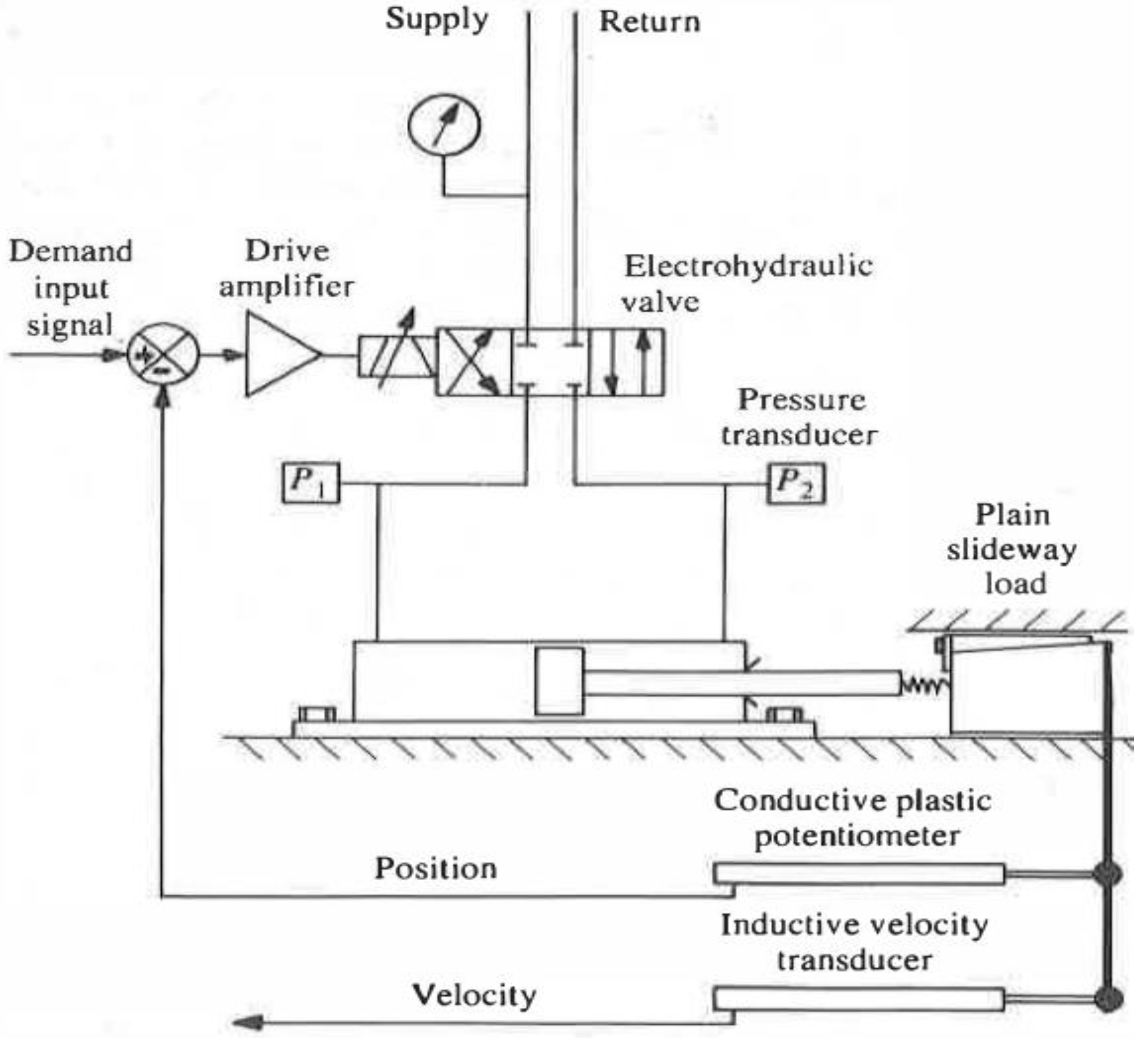
Figure 2.
Power Bonding routine.

Figure 3.
Moog 76 model 102 flow control valve [12].
Figure 3.
Moog 76 model 102 flow control valve [12].
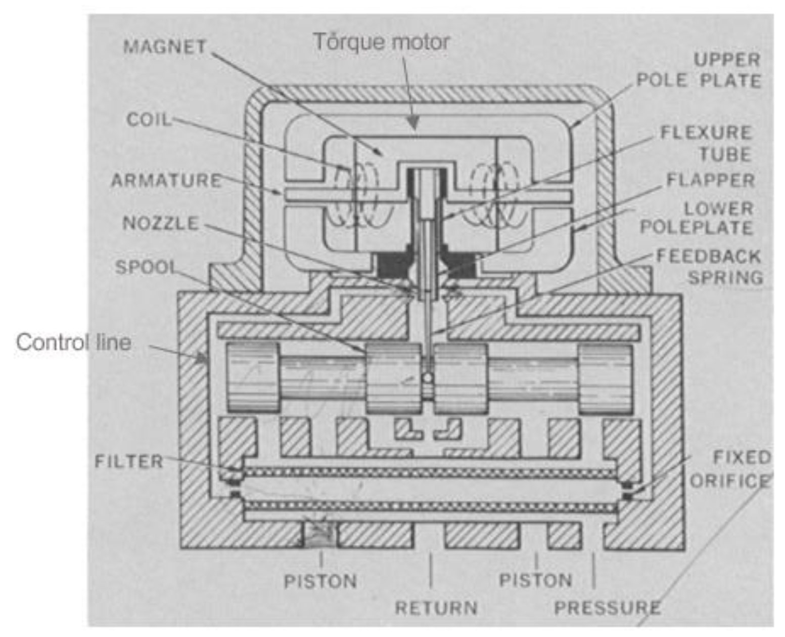
Figure 4.
Valve model block diagram.
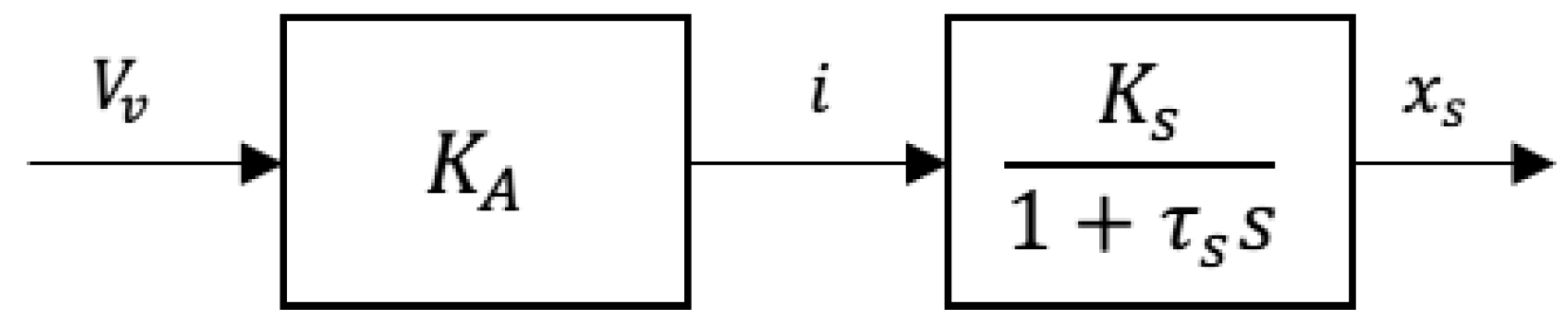
Figure 5.
Physical layout of the four-way valve controlled asymmetric cylinder [8].
Figure 5.
Physical layout of the four-way valve controlled asymmetric cylinder [8].
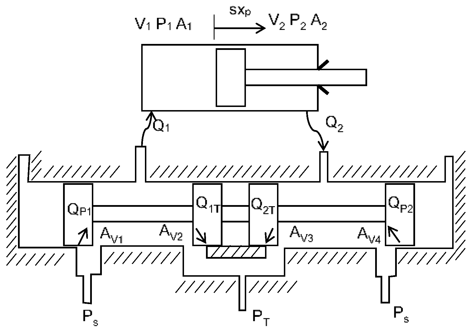
Figure 6.
Theoretical and actual situation of a zero-lapped valve [8] .
Figure 6.
Theoretical and actual situation of a zero-lapped valve [8] .
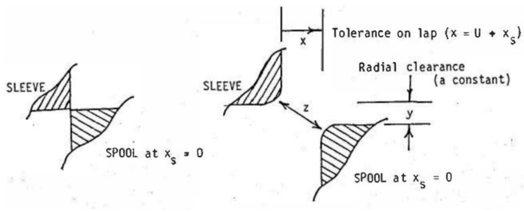
Figure 7.
Flow gain model block diagram.
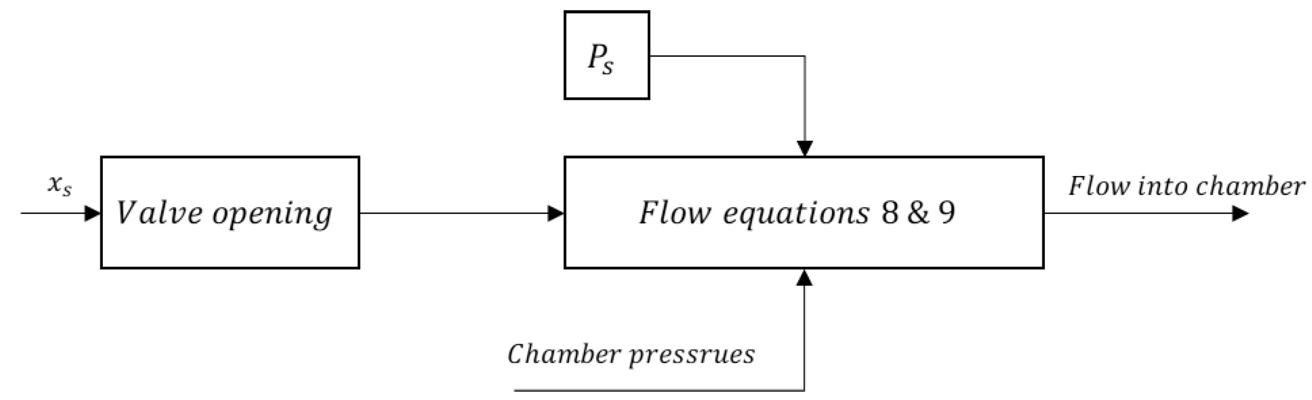
Figure 8.
The actuator model block diagram.
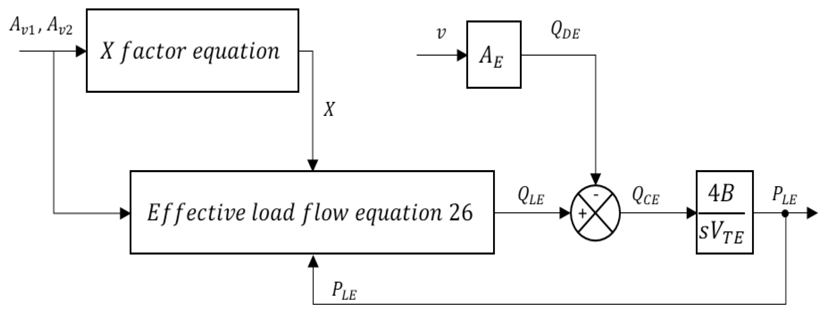
Figure 9.
The load model block diagram.
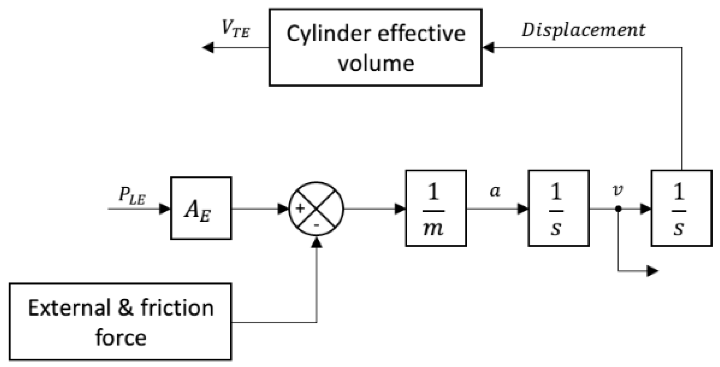
Figure 10.
Chamber pressures when the valve in underlap state.
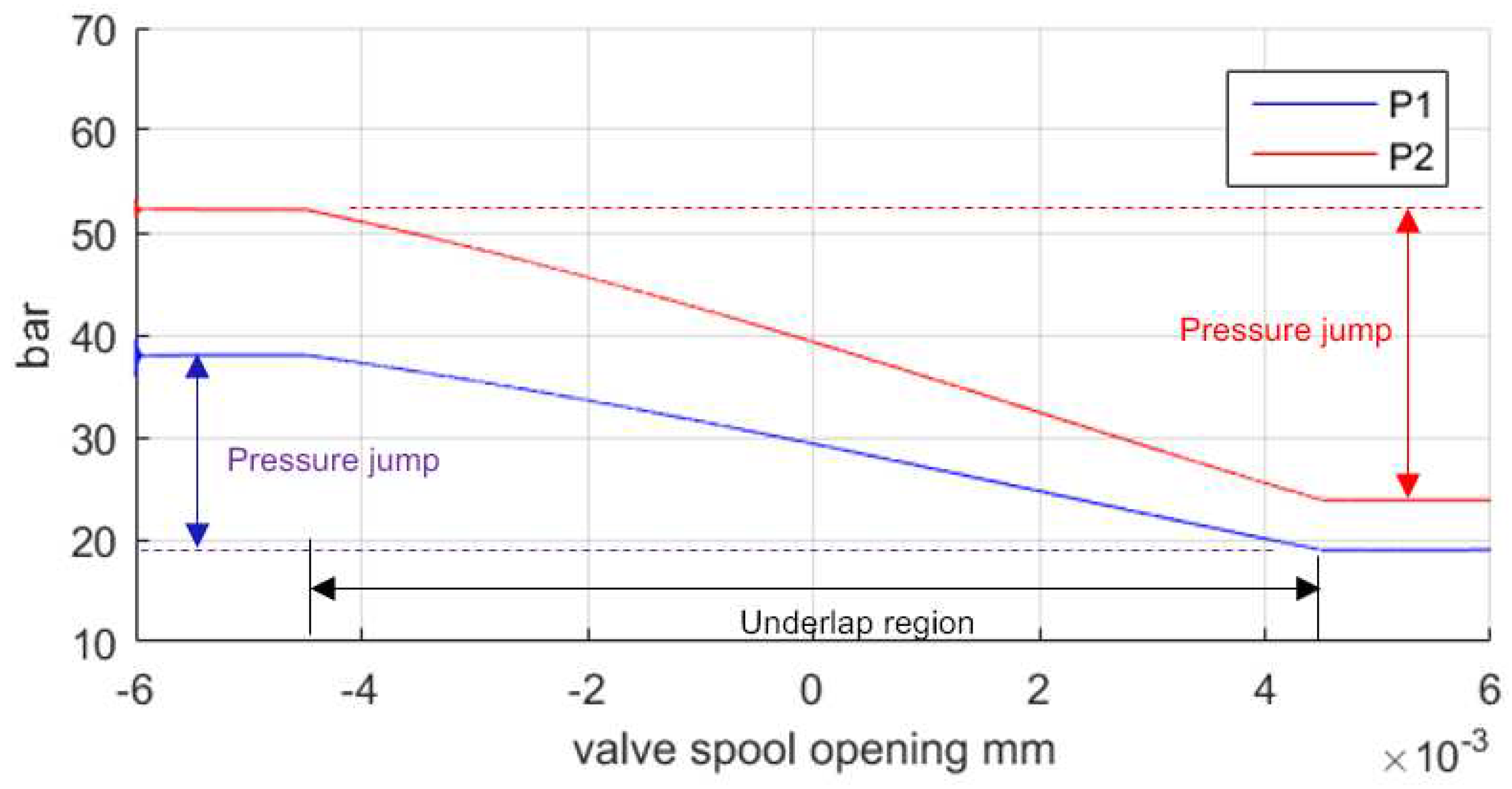
Figure 11.
Four X roots in underlap region (a) and Numerically solved X factor (b).
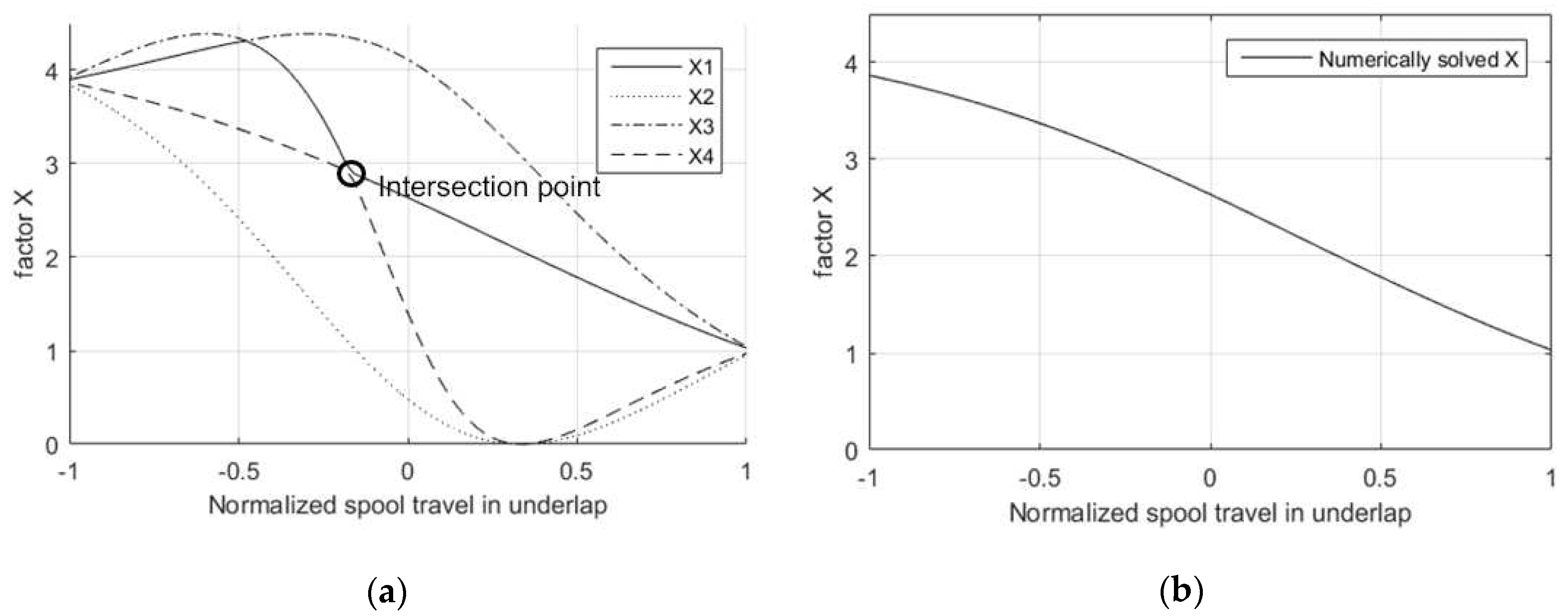
Figure 12.
Overall component linking model block diagram.
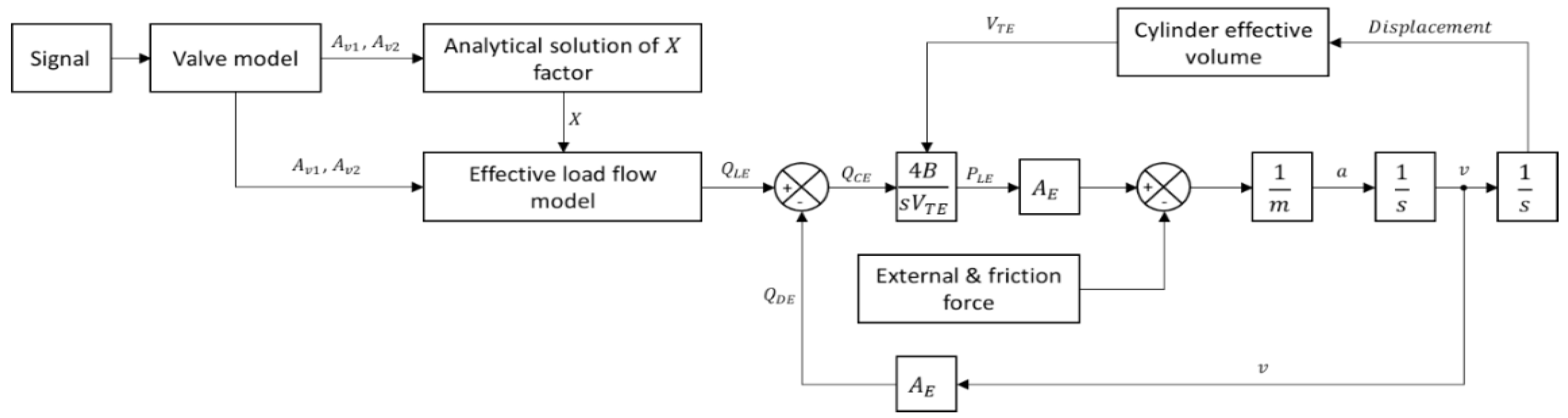
Figure 13.
Component linking model of Moog valve controlled system in Matlab Simulink.
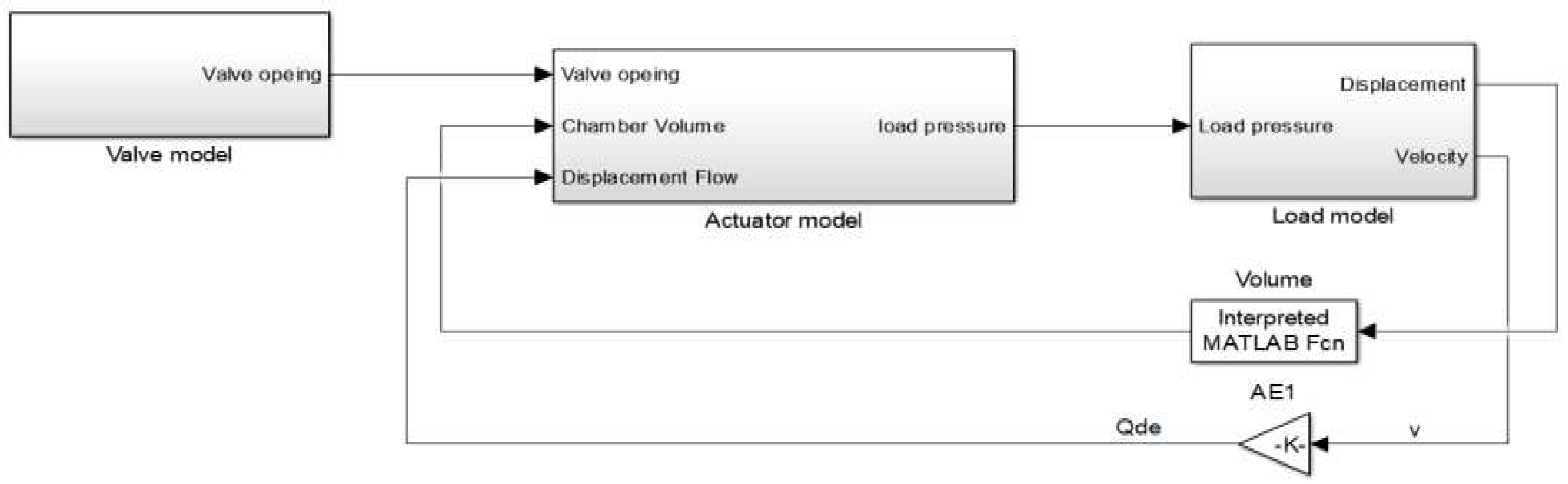
Figure 14.
90mm/s cylinder velocity simulation results vs experimental results:(a)Simulink results; (b)FORTRAN simulation results; (c)Experimental results.
Figure 14.
90mm/s cylinder velocity simulation results vs experimental results:(a)Simulink results; (b)FORTRAN simulation results; (c)Experimental results.
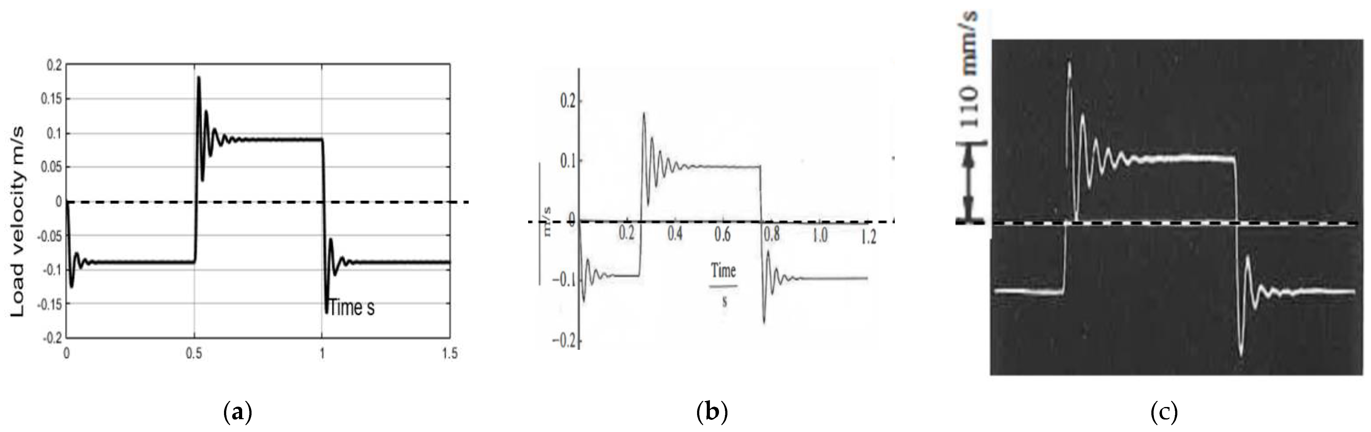
Figure 15.
90mm/s load pressure simulation results vs experimental results:(a)Simulink results; (b)FORTRAN simulation results; (c)Experimental results.
Figure 15.
90mm/s load pressure simulation results vs experimental results:(a)Simulink results; (b)FORTRAN simulation results; (c)Experimental results.
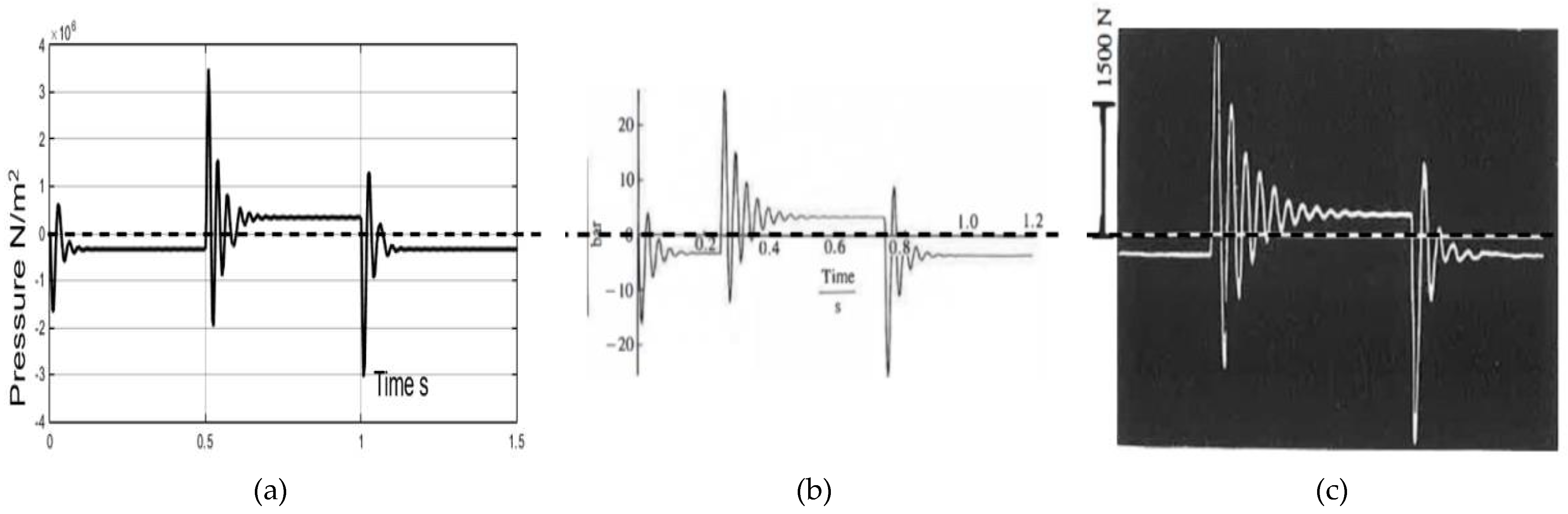
Figure 16.
(a) Analytical solve and (b) numerical solve results of square wave velocity motion.
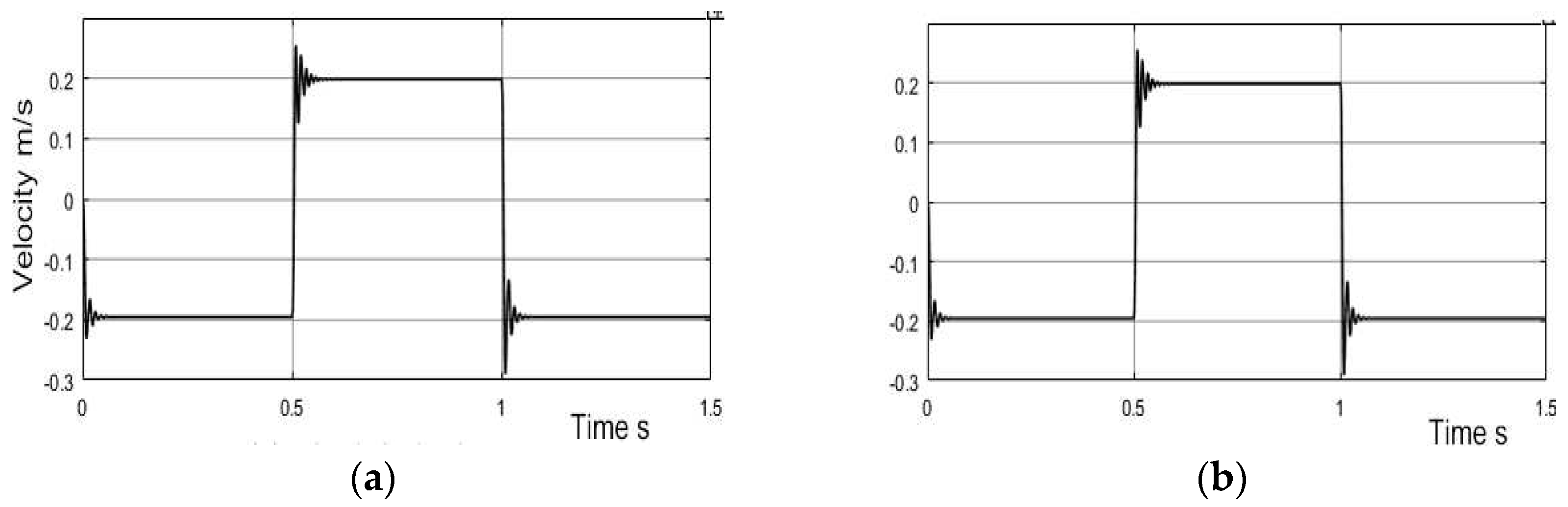
Figure 17.
(a) Analytical solve and (b) numerical solve of sawtooth velocity simulation results.
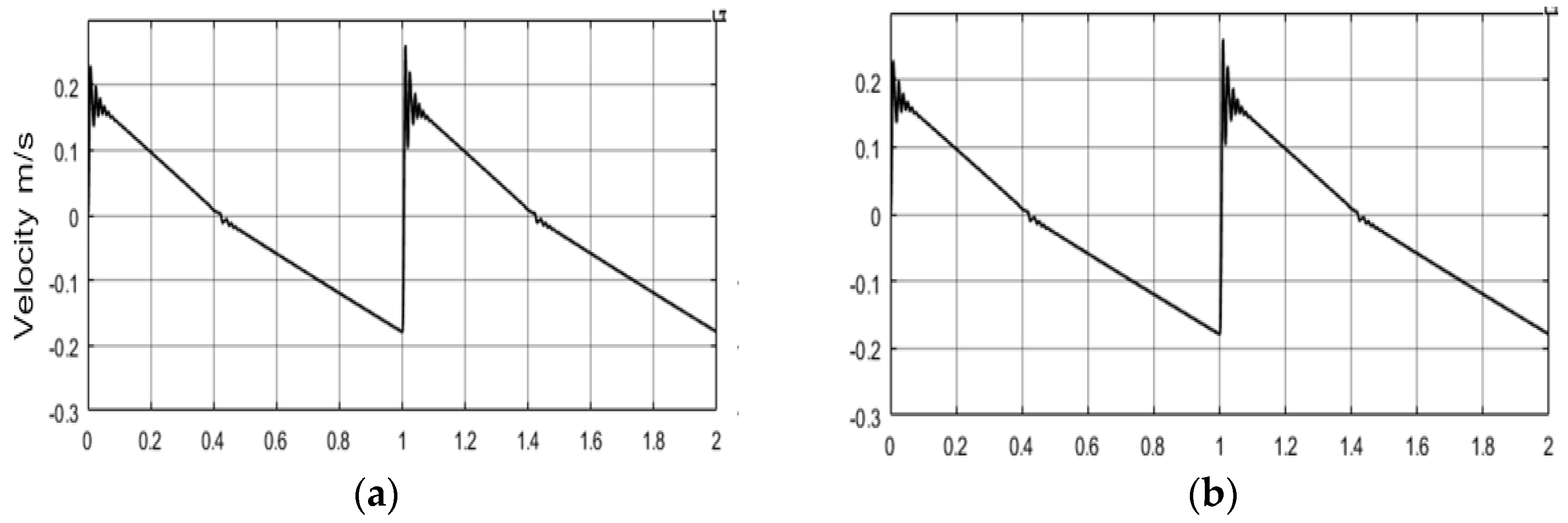
Figure 18.
(a) Numerical solving results and (b) analytical solving results of chamber pressures when valve travel within underlap region.
Figure 18.
(a) Numerical solving results and (b) analytical solving results of chamber pressures when valve travel within underlap region.
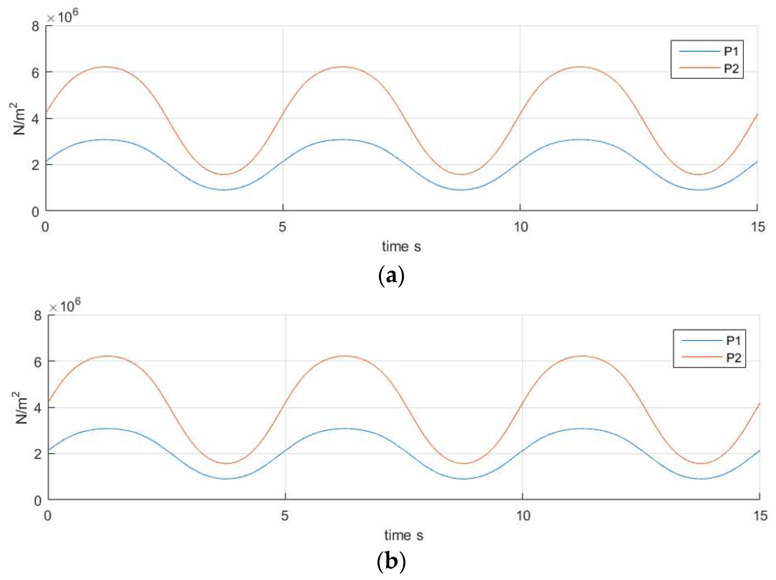

Table 1.
Identify root from numerically solving results when area ratio is 1.9707.
| (mm) | Factor | Root |
|---|---|---|
| -0.0045 | 3.883617722 | |
| -0.004404 | 3.867534491 | |
| -0.004296 | 3.848941124 | |
| -0.004101 | 3.814000308 | |
|
| ||
| -0.0009 | 2.963117621 | |
| -0.000753 | 2.911892307 | |
| -0.000735 | 2.905559937 | |
| 0 | 2.637188916 | |
| 0.0012 | 2.172727301 | |
| 0.00255 | 1.65272018 | |
|
| ||
| 0.004101 | 1.119970977 | |
| 0.0042 | 1.0894822 | |
| 0.004302 | 1.058563937 | |
| 0.00441 | 1.026380398 | |
| 0.0045 | 1 | |
Table 2.
Root distribution of X4 and X1 with different area ratios.
| 1.5 | 46% | 54% |
| 1.9707 | 41.67% | 58.33% |
| 2.5 | 39% | 61% |
| 3 | 37% | 63% |
| 4 | 33.3% | 66.7% |
Table 3.
Simulation time cost of numerical, analytical and fundamental methods.
| Square wave simulation | |
|---|---|
| Numerical solved time cost | Analytical time cost |
| 5.49 seconds | 1.07 seconds |
| Underlap region simulation | |
| Numerical solved time cost | Analytical time cost |
| 1647.17 seconds | 8.50 seconds |
| Sawtooth command simulation | |
| Numerical solved time cost | Analytical time cost |
| 8.26 seconds | 1.23 seconds |
Disclaimer/Publisher’s Note: The statements, opinions and data contained in all publications are solely those of the individual author(s) and contributor(s) and not of MDPI and/or the editor(s). MDPI and/or the editor(s) disclaim responsibility for any injury to people or property resulting from any ideas, methods, instructions or products referred to in the content. |
© 2023 by the authors. Licensee MDPI, Basel, Switzerland. This article is an open access article distributed under the terms and conditions of the Creative Commons Attribution (CC BY) license (http://creativecommons.org/licenses/by/4.0/).
Copyright: This open access article is published under a Creative Commons CC BY 4.0 license, which permit the free download, distribution, and reuse, provided that the author and preprint are cited in any reuse.