
Submitted:
13 December 2023
Posted:
14 December 2023
You are already at the latest version
Abstract
The synchronization of laser and X-ray sources is essential for time-resolved measurements in the study of ultrafast processes, including photo-induced piezo-effect, shock wave generation, and phase transition. On the one hand, the optical diagnostics (by synchronization of two laser sources) provides information about change in vibration frequencies, shock waves dynamics, linear and nonlinear refractive index behavior. On the other hand, the optical pump – X-ray probe diagnostics give opportunity to directly reveal the lattice dynamics. To integrate two approaches into a unified whole one need to create a robust method for synchronization of two systems with different repetition rate up to MHz range. In this paper, we propose a universal approach utilizing a field-programmable gate array (FPGA) to achieve precise synchronization between different MHz sources such as various lasers and synchrotron X-ray sources. This synchronization method offers numerous advantages, such as high flexibility, fast response, and low jitter. Experimental results demonstrate successful synchronization of two different MHz systems with a temporal resolution of 250 ps for these systems. This enables ultrafast measurements with sub-nanosecond resolution, facilitating the uncovering of complex dynamics in ultrafast processes.
Keywords:
FPGA
; synchrotron radiation source
; ultrashort lasers
; synchronization
1. Introduction
The understanding of atomic structure plays a dominant role in scientific research. Significantly, important discoveries concerning structural information have often paved the way for the emergence of new fields. For instance, the observation of X-ray diffraction from crystal lattices laid the groundwork for modern solid-state physics, demonstrating that crystal structures can be obtained through the measurement of X-ray diffraction patterns [1]. However, traditional diffraction methods have primarily provided a static view of the structure. While time-resolved methods have allowed for the measurement of structural changes, directly observing the atomic motions underlying these changes has remained elusive. The timescale for these changes typically falls within the femtosecond range, approximately from 10-12 to 10-14 seconds, comparable to the duration of molecular vibrations. Although femtosecond laser pulses have enabled optical measurements with femtosecond resolution, optical techniques alone cannot offer a direct view of the atomic structure [2,3]. In a typical pump-probe experiment, the pump pulse is used to excite the system, inducing changes in its electronic, vibrational, or structural properties. These changes are monitored by the probe pulse to measure the resultant response [3].
By varying the time delay between the pump and probe pulses, the evolution of the system's dynamics can be captured with ensured temporal resolution [4,5,6]. Detection of the probe signal can be accomplished using a range of techniques, including photodiodes, streak cameras, transient absorption spectroscopy, or time-resolved spectroscopy [7]. These methods allow for the measurement of various optical properties, such as absorption, reflectivity, transmission, or emission, as a function of the time delay between the pump and probe pulses [8,9].
In optical pump-probe diagnostics, information regarding structural changes has only been indirectly inferred from the secondary effects exerted on optical properties. Therefore, it is necessary to integrate these methods with X-ray time-resolved techniques to obtain comprehensive information about the dynamics of the medium [10,11]. Development of ultrashort X-ray pulses holds great significance as it enables physical experiments that combine femtosecond time resolution with atomic-scale spatial resolution [12,13]. To achieve temporal resolution, it is necessary to synchronize two different sources of laser and/or X-ray radiation [14]. The difficulty of synchronization procedure strongly depends on the type of the X-ray source. Such sources as X-ray Free Electron Laser are almost naturally synchronized with other lasers with picosecond and sub-picosecond temporal resolution [12]. However, the maximum achieved time delays are mostly limited by several nanoseconds [15,16]. By synchronizing these sources, researchers can conduct sophisticated time-resolved experiments that capture the dynamics of ultrafast processes on natural atomic and temporal scales. The second commonly applied method of X-ray generation is laser-plasma sources [17]. Using high-intensity femtosecond lasers, it becomes possible to generate high-brightness X-ray radiation, which can be used for time-resolved measurements in the pump-probe approach [18]. The time resolution in such a setup is achieved by mechanically moving the delay line [17]. The time resolution is usually about sub-ps, and, the maximal obtained information is limited by several nanoseconds. Finally, one of the most important sources is the synchrotron, however its synchronization with laser sources is most complex. The synchronization in this case is commonly achieved by phase-locked loop (PLL) systems, which give the opportunity to investigate the dynamics only up to several nanoseconds with a time resolution of tens of picoseconds [19]. To extend the time delays further, up to the microsecond regime, the incorporation of electronic time delays becomes necessary.
In this manuscript, we propose a multimodal hybrid approach for an all-optical and X-ray time-resolved diagnostics. The key component of the approach is the synchronization system, which utilized a field-programmable gate array (FPGA) for the synchronization of two different laser sources or an X-ray synchrotron source and a nanosecond laser system. The FPGA-based synchronization method offers several advantages, such as high flexibility and reconfigurability, fast response, and low jitter and the possibility to change the time delay with no limitations in a maximal value. By leveraging these benefits, we aim to address the challenges associated with achieving precise timing control between different laser systems and a synchrotron with a nanosecond laser. The fine temporal resolution offered by the FPGA-based synchronization technique allows for a comprehensive understanding of the intricate dynamics underlying these processes. We employed two different approaches using FPGA-based synchronization systems to investigate the dynamics of crystal lattices irradiated by intense laser pulses. Firstly, we utilized a pump-probe optical diagnostic technique to observe the formation of micromodification and shock wave generation induced by laser pulses in silicon (Si). Secondly, we employed an optical-pump - X-ray probe technique to retrieve the dynamics of a lithium niobate (LiNbO3) lattice irradiated by a nanosecond laser pulse. Both approaches provided the opportunity to observe the dynamics of ultrafast processes with a nanosecond time resolution on sub-millisecond timescales. In the optical pump-probe diagnostics we used the trigger from femtosecond laser (pump) to generate delay for the nanosecond laser source (probe). In the optical pump – X-ray probe diagnostics we initially decreased the initial RF signal frequency to 5 Hz and only after that added the time delay to trigger signal. This provides flexibility in manipulating the period, shift, and duty cycle of the control TTL signals over a wide range of parameters, while maintaining robust synchronization to the initial signal. Additionally, there is no limitation on the maximum time delay, allowing for the observation of the complete evolution of the system perturbed by the pump pulse. Both approaches complement each other, which can provide a comprehensive characterization of the process of ultrafast laser pulse interaction with the crystalline lattice
2. Materials and Methods
2.1. Optical pump-probe diagnostics
In our experiments, we utilized the pump-probe technique, as shown in Figure 1a. The pump laser pulse (100 μJ, 1030 nm, 200 fs), was tightly focused onto the sample boundary. The probe pulse was used to measure and analyze the effects induced by the pump pulse, see Figure 1a. To achieve the desired temporal resolution, we implemented an electronic delay circuit using FPGA and analog electronics. The NI CompactRio served as the primary controller for trigger control. At the FPGA level, the trigger from the femtosecond laser system (Avesta TETA 20) could be shifted with a timestep of 10 ns, based on the 100 MHz internal clock of the FPGA (see Figure 1b). The frequency of the pump pulse could reach up to 4 kHz, but due to the irreversible changes in the sample's boundary, it was set to 100 Hz, see Figure 1b. This ensured that the sample had enough time to recover between each pump-probe cycle. For fine time delays, a custom analog circuit was utilized, allowing for increments of 250 ps. This circuit added the desired time delay to the trigger signal, as it marked in the Figure 1b. The jitter, or timing variability, of the electronic circuit was measured to be less than one nanosecond using a 1 GHz oscilloscope. This ensured precise and accurate control over the timing of the trigger pulses, minimizing any unwanted fluctuations or uncertainties in the experimental setup.
As the probe pulse, we utilized laser pulses generated by two different laser systems: Laser Export Tech 527 (wavelength of 527 nm, time duration of 4 ns, and energy up to 100 µJ) and the Quantel Brio (wavelength of 532 nm, time duration of 4 ns, and energy up to 100 mJ). To generate shock waves and observe micromodification, we tightly focused an infrared femtosecond laser pulse onto the silicon plate surface. The numerical aperture (NA) of the focusing objective was set to 0.45. Simultaneously, an unfocused nanosecond laser pulse was directed to the same point on the sample at an incident angle of 30 degrees. The reflected light from the sample was collected using a microscopic objective with 100x magnification, and the signal was recorded by a CCD camera (MindVision, China), see Figure 1a. By varying the time delay between the pump and probe pulses, we were able to observe the formation of micromodification and the generation of shock waves. After observing these phenomena, we focused the probe beam onto the sample and replaced the camera with a photodetector (ODA-03B, Avesta, Russia). The signal from the photodetector was acquired using a Python oscilloscope, which was controlled via LAN. All measurements were fully automated using custom software based on LabVIEW. This software facilitated the control and synchronization of the laser pulses, acquisition of the reflected signal, and capturing of photographs of the shock waves. The evolution of the reflected signal and photographs of the shock waves were observed over a 15 timescale with a time step of 1 ns.
2.2. Optical pump - X-ray probe diagnostics
The X-ray-optical experiments took place at the "RKFM" beamline, dedicated to X-ray crystallography and physical materials science, within the Kurchatov Synchrotron Radiation Source "KISI-Kurchatov". The successful implementation of synchronization techniques at the "Phase" beamline has expanded the capabilities in experiments at the RKFM beamline [20]. The RKFM beamline gives an opportunity to decrease the diameter of the X-ray beam on the sample up to several micrometers. The beamline design comprises three distinct modules: the X-ray diffraction module (RKFM station), the laser-matter interaction setup, and a synchronization system. All measurements were carried out under ambient room temperature conditions.
2.2.1. X-ray diffraction module
Initially, a bending magnet was employed to generate polychromatic synchrotron radiation, which was subsequently collimated using water-cooled slits. The next step involved the monochromatization of the σ-polarized synchrotron radiation. This was achieved by utilizing two horizontally positioned Si single crystals with high structural perfection and symmetric reflections along the (111) plane. These crystals enabled a relative energy divergence of 2·10^-4. The monochromator was tuned to an energy of 12.000 keV, corresponding to the brightest section of the bending magnet's spectrum. The resulting beam was further refined through the use of slits with an aperture measuring 0.5 × 0.2 mm.
The characterized beam, which exhibited a temporal structure mirroring the bunch structure of the storage ring, was directed towards a sample placed within an optically transparent crystal holder. The sample, along with the crystal holder, was mounted on the goniometric system of a Huber multicircle diffractometer (see Figure 1c).
The sample used, LiNBO3, was adjusted to the 0012 X-ray reflection with a precise Bragg angle of 26.562°. This reflection possessed an extinction depth of 3.7 μm and an intrinsic reflectivity half-width of approximately 2.0 arcsec. To capture the intensity, a transmission avalanche photodiode detector from FMB Oxford was positioned at the sample's double Bragg angle. The recorded intensity data was then transmitted to a Python multichannel oscilloscope analyzer (Rudnev-Shilyaev), which offered a sampling rate of 1 GHz and 14-bit resolution.
2.2.2. Laser-matter interaction setup
To initiate the piezo-effect in the LiNbO3 sample, a Quantel Brio nanosecond laser was employed. The laser had a maximum pulse energy of 125 mJ, a pulse duration of 6 ns, a repetition rate of 5 Hz, and a focusing spot diameter of 500 μm at an intensity level of 1/e^2 and a wavelength of 1064 nm, that further doubled in the nonlinear crystal. Spatial alignment of the laser and X-ray beams was accomplished using a system of mirrors. The laser beam was focused into the sample using a 250 mm focusing lens. Additionally, the laser pulse energy was varied using a Glan prism.
2.2.3. Synchronization system
In our experiments, we employed the optical pump - X-ray probe concept, in which the time delay between the laser and X-ray pulses was varied. To achieve synchronization, the laser radiation was synchronized with the rotation period of electron bunches in the SR storage ring. The KISI-Kurchatov synchrotron's storage ring operated in the N-bunches mode, with a total of 75 electron bunches and an orbital period of 414 ns. Each bunch had a duration of approximately 140 ps.
For synchronization, we utilized a home-built system based on a field-programmable gate array (FPGA). The FPGA allowed us to create reconfigurable electronic circuits with low time jitter. In our setup, the high-frequency RF signal generator of the storage ring (operating at 2.415 MHz) served as the external clock for the FPGA-based system, ensuring robust synchronization of all signals with the circulating electron bunches. The frequency of the controlling signal was then reduced to 5 Hz by counting down 490,200 ticks of the external trigger, as illustrated in Figure 2. Signals at a frequency of 5 Hz were used to initiate the lamp and control the electro-optical shutter of the nanosecond laser, with the desired time delays between them, see Figure 1d.
To achieve temporal diagnostics, the analog part of the synchronization system introduced a controlled delay to the laser trigger signal, with a step of 1 ns. Since the electron bunches on the synchrotron radiation source followed each other with a period of 411 ns, it was necessary to vary the delay within the range of 0–411 ns. The analog signal from the transmission detector was recorded in the time scan of an oscilloscope, with a resolution of 1 ns, synchronized with the laser pulse cycle. The total duration of the time window was 32.768 μs. The synchronization system's operating principle is depicted in Figure 2.
By summing the X-ray diffraction signals for 82 different time delays (414ns/5ns), we obtained a comprehensive picture of the temporal changes in the X-ray diffraction signal. The temporal resolution is potentially limited by the duration of the electron bunch, in our case, 140 ps (2σ). The recorded time signal, on the other hand, is restricted only by the measurement system. In our setup, we used a transmission detector and a Python digital oscilloscope (Rudnev-Shilyaev, Russia). The process of changing the time delay and recording the signal from the detector was fully automated using custom software that controlled the entire registration system via LAN and RS232 connections.
3. Results and discussion
3.1. Optical diagnositcs of shock wave generation and micromodification formation
The optical diagnostics could reveal the first stages of laser ablation of Si. The magnified image of the surface reveals distinct phenomena occurring after laser impact on the timescale of approximately 100 ns. Combination of time resolved microscopy and time resolved reflectance give opportunity to reveal the evolution of the laser impact on the material. Prior to the formation of a micromodification, a darkened region emerges, leading to a rapid decrease in reflection. This is indicated by the inset in Figure 2. Subsequently, a shock wave is generated, accompanied by the formation of a micromodification. Initially, the size of the micromodification is larger than its residual size, but the reflection coefficient is higher, as shown by the modification profiles in the inset of Figure 2. The size of the residual micromodification stabilizes at around 1 μs, as evidenced by the transverse profile of the resulting micromodification. Plasma luminescence in the center of the profile appears as a bright dot. Increasing the delay between the pump and probe pulses leads to a decrease in the albedo of the affected area until it reaches saturation. Additionally, the region where albedo change is observed decreases for longer time delays, see Figure 2. Laser ablation induces high pressures and temperatures, resulting in the generation of a shock wave [21]. The laser-induced shock wave propagates from the impact area at a velocity of approximately 15 km/s, leaving the spatial overlap region between the laser and X-ray beams in approximately 4 μs. Notably, behind the shock wave front, the presence of dark regions, indicating a change in albedo, is observed. The change of the albedo could serve as an indicator of phase transitions.
3.2. X-ray time resolved diagnostics of the piezo-effect in LiNbO3
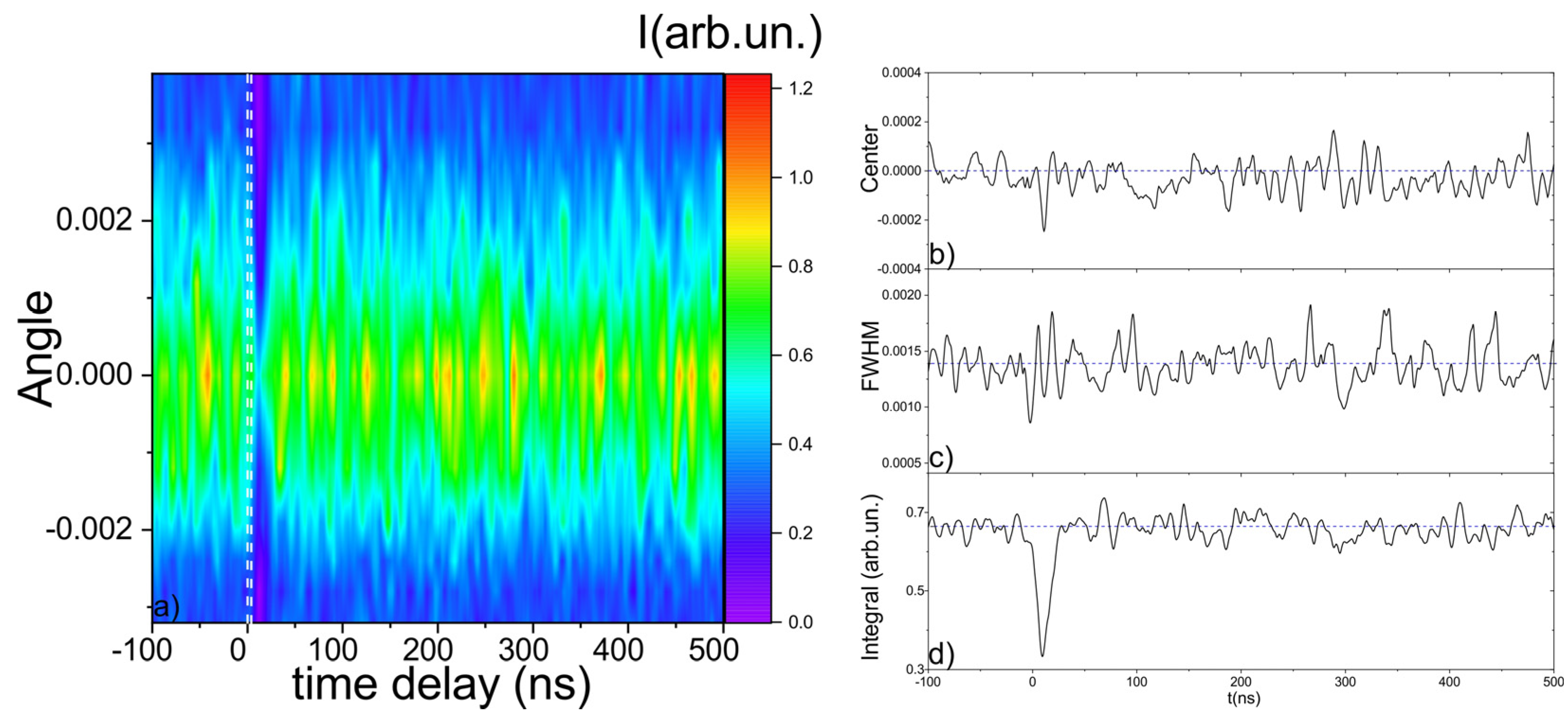
Compared to optical pump-probe diagnostics, X-ray time-resolved diagnostics of lattice dynamics induced by laser impulses are more intricate. One of the key challenges is the requirement to measure the X-ray rocking curve for all time delays. This entails obtaining time-resolved dynamics for at least five different diffraction angles. The resulting dynamics can be visualized as a "heat map," with the diffraction angle and time delay as axes, see Figure 3a. This visualization helps to capture the complex temporal evolution of lattice dynamics induced by the laser pulses. The analysis of such heat maps provides valuable insights into the structural and dynamical changes occurring in the material on ultrafast timescales.
We perform the measurement of the X-ray rocking curve for 8 angles and for 32 microseconds after laser impact and with 1 nanosecond time step. From the heat map we also calculated the evolution of the rocking curve width (at FWHM) and the evolution of the shift of the center of gravity, that was calculated using Eq. (1), see Figure 3.
where θ0 is center of gravity, θi is diffraction angle and the Ii is intensity of X-ray obtained for this angle
In our experiment, we conducted measurements of the X-ray rocking curve for a total of 8 different angles. These measurements were performed over a 32 microseconds time interval after the laser impact, with a time step resolution of 1 nanosecond. By analyzing the obtained data, we constructed a heat map that visualizes the dynamics of the X-ray rocking curve as a function of both diffraction angle and time delay. Additionally, we extracted valuable information from the heat map by calculating the evolution of three key parameters: the width of the rocking curve at the full width at half maximum (FWHM), integral of the signal for different angles and the shift in the center of gravity. The center of gravity shift was determined using Equation (1), which provides a quantitative measure of the displacement of the diffraction peak due to lattice dynamics induced by the laser impulse.
By analyzing the evolution of the rocking curve width and center of gravity shift over time, we gain valuable insights into the structural and dynamical changes occurring in the material following the laser impact. These measurements and calculations provide important information for understanding the behavior of the lattice dynamics and its response to the laser-induced excitation. The "heat map" generated from the X-ray rocking curve measurements clearly reveals the moment of laser impact on the sample, marked as white lines in Figure 3. Immediately after the laser impact, there is a noticeable decrease in the integral of the rocking curve. This reduction is attributed to the disorganization of atoms within the material. Additionally, the center of gravity of the rocking curve exhibits slight oscillations during this initial period. The main dynamics of the lattice can be observed over a time interval of approximately 100 ns following the laser impact. This time period is characterized by significant changes in the structural and dynamical properties of the material. These dynamics may include processes such as lattice rearrangement, energy transfer, and relaxation phenomena. The detailed analysis of this 100 ns time interval provides important insights into the behavior of the material under the influence of the laser impulse.
4. Conclusion
In this study, we employed both optical pump-probe and X-ray time-resolved diagnosis to investigate the lattice dynamics induced by laser pulses on a sample material. Both approaches complement each other and provide the opportunity to observe the dynamics of ultrafast processes with a nanosecond time resolution on sub-millisecond timescales. The optical pump-probe diagnosis allows us to observe the formation of micromodifications and the generation of shock waves following the laser impact. The X-ray time resolved diagnostic captured the intricate temporal evolution of the material's structure. We observed a clear moment of laser impact, characterized by a drop in the integral of the rocking curve and slight oscillations in the center of gravity.
Both methods indicate the disordering of atoms and the immediate response of the lattice to the laser pulse. Furthermore, the main dynamics of the lattice were found to occur within a 100 ns time interval after the laser impact. This period exhibited significant changes in the structural and dynamic properties of the material. Processes such as lattice rearrangement, energy transfer, and relaxation phenomena likely contributed to these observed dynamics. The detailed analysis of this time interval allowed us to gain a deeper understanding of the material's behavior under the influence of the laser pulse. Overall, our findings demonstrate the complementary nature of optical pump-probe and X-ray time-resolved diagnostics in studying the lattice dynamics induced by laser pulse. The optical techniques provided valuable information about the formation of micromodifications and shock waves, while the X-ray methods allowed for a more detailed and complex analysis of the material's structural changes. Together, these results enhance our understanding of the ultrafast dynamics of materials and have implications for various scientific and technological applications.
Author Contributions
Conceptualization, F.P. and E.M.; methodology, F.P. ,E.M., A.K.; software, E.M.; validation, E.I.,. and F.Pi.; formal analysis, N.M.; investigation, all authors.; resources, F.P, N.M. and Y.P..; data curation, E.M.; writing—original draft preparation, E.M. and F.P.; writing—review and editing, all authors; visualization, E.M.; supervision, F.P.; project administration, N.M.; funding acquisition, E.M. and F.P. All authors have read and agreed to the published version of the manuscript.
Funding
Russian Science Foundation, grant № 23-73-00039. The optical pump-probe technique funded by framework of State Assignment to the FSRC «Crystallography and Photonics», RAS in part of using the equipment of the Center for Collective. The time-resolved X-ray optical approach funded by framework of Program of development of Moscow university and National project “Science and universities”.
Data Availability Statement
The data is not publicly available.
Conflicts of Interest
The authors declare no conflict of interest.
References
- Fetisov, G. V. X-ray Diffraction Methods for Structural Diagnostics of Materials: Progress and Achievements. Uspekhi Fiz. Nauk 2020, 190, 2–36. [CrossRef]
- Mareev, E.; Potemkin, F. Dynamics of Ultrafast Phase Transitions in - MgF 2 Triggered by Laser - Induced THz Coherent Phonons. Sci. Rep. 2022, 1–8. [CrossRef]
- Mareev, E.; Minaev, N.; Epifanov, E.; Tsymbalov, I.; Sviridov, A.; Gordienko, V. Time-Resolved Optical Probing of the Non-Equilibrium Supercritical State in Molecular Media under Ns Laser-Plasma Impact. Opt. Express 2021, 29, 33592. [CrossRef]
- Li, R.; Ashour, O.A.; Chen, J.; Elsayed-Ali, H.E.; Rentzepis, P.M. Femtosecond Laser Induced Structural Dynamics and Melting of Cu (111) Single Crystal. An Ultrafast Time-Resolved X-ray Diffraction Study. J. Appl. Phys. 2017, 121. [CrossRef]
- Pushkin, A.; Migal, E.; Suleimanova, D.; Mareev, E.; Potemkin, F. High-Power Solid-State Near- and Mid-IR Ultrafast Laser Sources for Strong-Field Science. Photonics 2022, 9, 1–20. [CrossRef]
- Guo, B.; Sun, J.; Lu, Y.F.; Jiang, L. Ultrafast Dynamics Observation during Femtosecond Laser-Material Interaction. Int. J. Extrem. Manuf. 2019, 1. [CrossRef]
- Noack, J.; Vogel, A. Single-Shot Spatially Resolved Characterization of Laser-Induced Shock Waves in Water. Appl. Opt. 1998, 37, 4092–4099. [CrossRef]
- Lindenberg, A.M.; Larsson, J.; Sokolowski-Tinten, K.; Gaffney, K.J.; Blome, C.; Synnergren, O.; Sheppard, J.; Caleman, C.; MacPhee, A.G.; Weinstein, D.; et al. Atomic-Scale Visualization of Inertial Dynamics. Science (80-. ). 2005, 308, 392–395. [CrossRef]
- Reiter, F.; Graf, U.; Serebryannikov, E.E.; Schweinberger, W.; Fiess, M.; Schultze, M.; Azzeer, a. M.; Kienberger, R.; Krausz, F.; Zheltikov, a. M.; et al. Route to Attosecond Nonlinear Spectroscopy. Phys. Rev. Lett. 2010, 105, 1–4. [CrossRef]
- Mcbride, E.E.; Krygier, A.; Ehnes, A.; Galtier, E.; Harmand, M.; Konˆ, Z. Phase Transition Lowering in Dynamically-Compressed Silicon. Nat. Phys. 2019. [CrossRef]
- Brown, S.B.; Gleason, A.E.; Galtier, E.; Higginbotham, A.; Arnold, B.; Fry, A.; Granados, E.; Hashim, A.; Schroer, C.G.; Schropp, A.; et al. Direct Imaging of Ultrafast Lattice Dynamics. Sci. Adv. 2019, 5, 1–8. [CrossRef]
- Trigo, M.; Dean, M.P.M.; Reis, D.A. Ultrafast X-ray Probes of Dynamics in Solids. 2021. [CrossRef]
- Siders, C.W.; Cavalleri, A.; Sokolowski-Tinten, K.; Tóth, C.; Guo, T.; Kammler, M.; Horn Von Hoegen, M.; Wilson, K.R.; Von Der Linde, D.; Barty, C.P.J. Detection of Nonthermal Melting by Ultrafast X-ray Diffraction. Science (80-. ). 1999, 286, 1340–1342. [CrossRef]
- Potemkin, F. V.; Mareev, E.I.; Garmatina, A.A.; Nazarov, M.M.; Fomin, E.A.; Stirin, A.I.; Korchuganov, V.N.; Kvardakov, V. V.; Gordienko, V.M.; Panchenko, V.Y.; et al. Hybrid X-ray Laser-Plasma/Laser-Synchrotron Facility for Pump-Probe Studies of the Extreme State of Matter at NRC “Kurchatov Institute.” Rev. Sci. Instrum. 2021, 92, 1–9. [CrossRef]
- Schropp, A.; Hoppe, R.; Meier, V.; Patommel, J.; Seiboth, F.; Ping, Y.; Hicks, D.G.; Beckwith, M.A.; Collins, G.W.; Higginbotham, A.; et al. Imaging Shock Waves in Diamond with Both High Temporal and Spatial Resolution at an XFEL. Sci. Rep. 2015, 5, 1–8. [CrossRef]
- Mcbride, E.E.; Krygier, A.; Ehnes, A.; Galtier, E.; Harmand, M.; Konˆ, Z. Phase Transition Lowering in Dynamically Compressed Silicon. Nat. Physics. 2019, 89–94. [CrossRef]
- Holtz, M.; Hauf, C.; Hernández Salvador, A.A.; Costard, R.; Woerner, M.; Elsaesser, T. Shift-Current-Induced Strain Waves in LiNbO3 Mapped by Femtosecond X-ray Diffraction. Phys. Rev. B 2016, 94, 1–7. [CrossRef]
- Martín, L.; Benlliure, J.; Cortina-Gil, D.; Haruna, A.; Ruiz, C. Validation of a Laser Driven Plasma X-ray Microfocus Source for High Resolution Radiography Imaging. Phys. Medica 2021, 82, 163–170. [CrossRef]
- Banchi, L.; Rossi, F.; Ferianis, M.; Bogoni, A.; Potì, L.; Ghelfi, P. Synchronization of 3GHZ Repetition Rate Harmonically Mode-Locked Fiber Laser for Optical Timing Applications. 8th Eur. Work. Beam Diagnostics Instrum. Part. Accel. DIPAC 2007 2007, 358–360.
- Kovalchuk, M. V.; Borisov, M.M.; Garmatina, A.A.; Gordienko, V.M.; Zheltikov, A.M.; Kvardakov, V. V.; Korchuganov, V.N.; Likhachev, I.A.; Mareev, E.I.; Mitrofanov, A. V.; et al. Laser-Synchrotron Facility of the National Research Centre “Kurchatov Institute.” Crystallogr. Reports 2022, 67, 717–728. [CrossRef]
- Norman, G.E.; Starikov, S. V.; Stegailov, V. V.; Saitov, I.M.; Zhilyaev, P.A. Atomistic Modeling of Warm Dense Matter in the Two-Temperature State. Contrib. to Plasma Phys. 2013, 53, 129–139. [CrossRef]
Figure 1.
(a) Experimental setup of optical pump – optical probe experiment; (b) synchronization scheme of optical pump – optical probe experiment; (c) experimental setup of optical pump – X-ray probe experiment; (d) synchronization scheme of optical pump – X-ray probe experiment.
Figure 1.
(a) Experimental setup of optical pump – optical probe experiment; (b) synchronization scheme of optical pump – optical probe experiment; (c) experimental setup of optical pump – X-ray probe experiment; (d) synchronization scheme of optical pump – X-ray probe experiment.
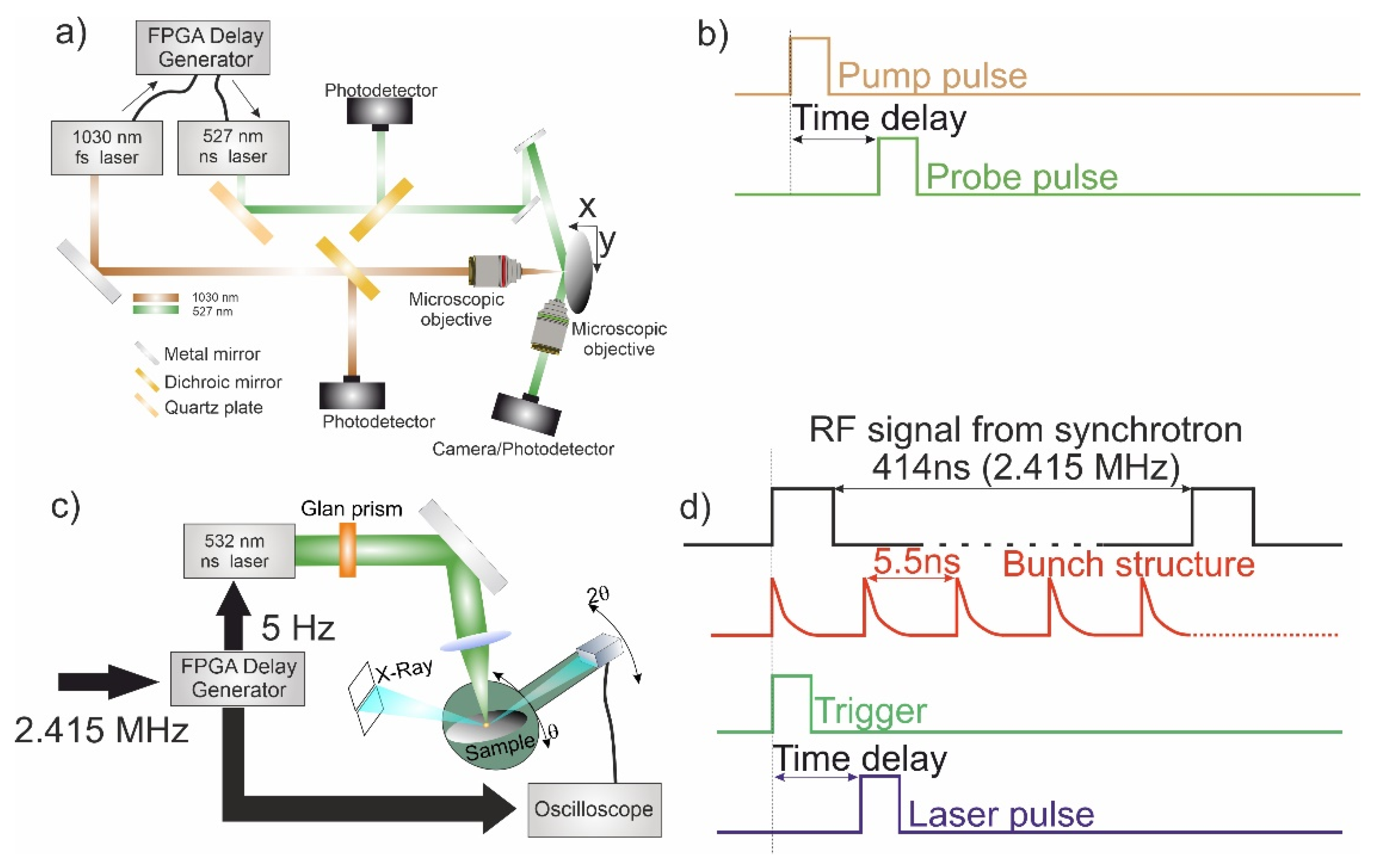
Figure 2.
Relationship between optical reflection (normalized to the initial value) and the delay between the pump and probe pulses is depicted. The inset provides visual representation of the affected area at specific time delays, where micromodifications are clearly discernible, along with the propagation of a shock wave originating from the impacted region. The white dot observed at the center of the image corresponds to the luminescence emitted by the laser-induced plasma. The bottom inset presents the profile of the affected area at different time delays along a line passing through the center of the micromodification. The peak at the center of the profile corresponds to the presence of laser-induced plasma.
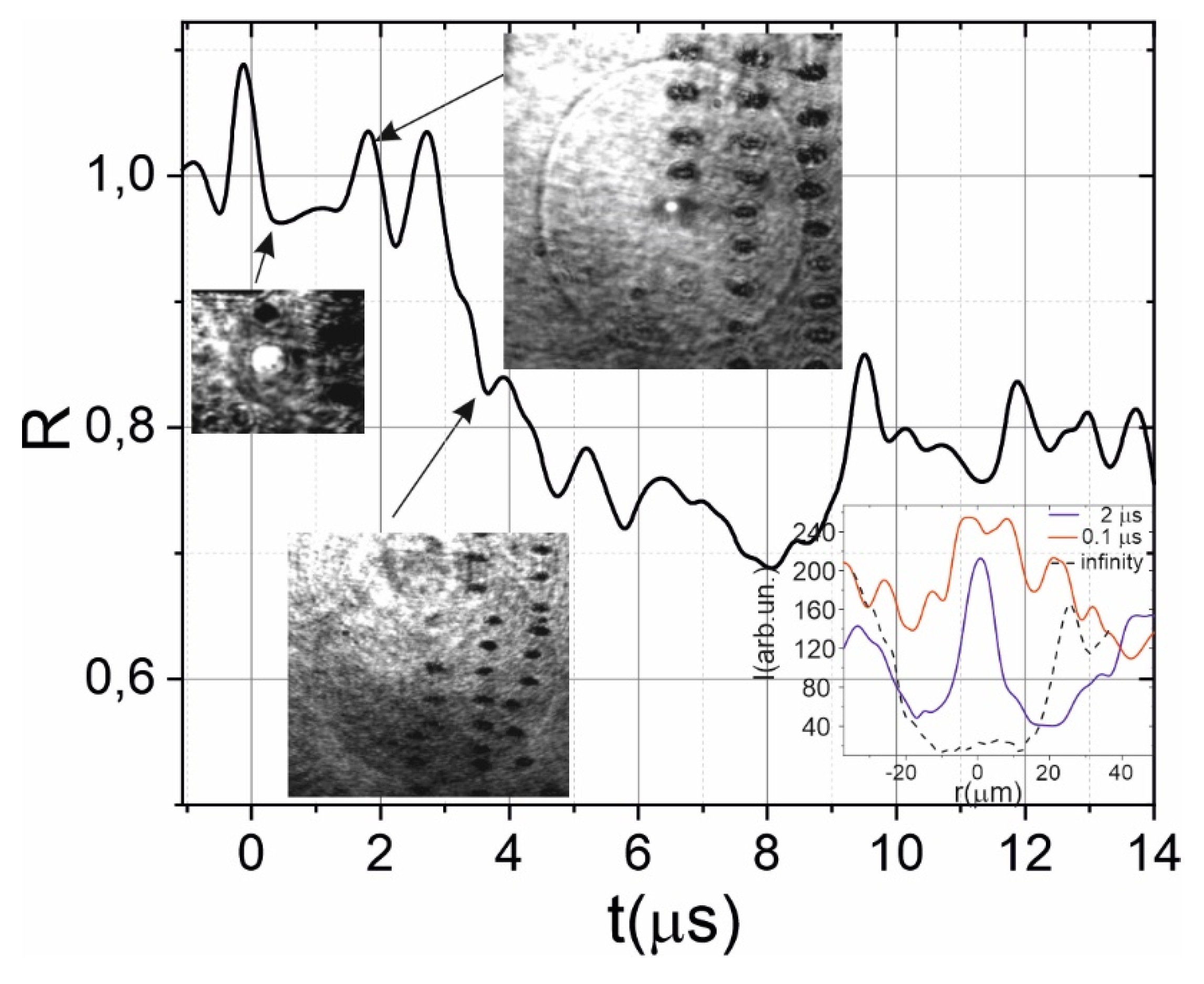
Figure 3.
Dynamics of X-ray rocking curve after laser impact on the LiNBO3. a) 3D “heat map”, white dotted lines shows the time interval of laser pulse impact b) dynamics of center of gravity shift c) dynamics of X-ray rocking curve width (FWHM) d) dynamics of the integral under X-ray rocking curve. The blue dotted lines shows the initial level on b)-c).
Disclaimer/Publisher’s Note: The statements, opinions and data contained in all publications are solely those of the individual author(s) and contributor(s) and not of MDPI and/or the editor(s). MDPI and/or the editor(s) disclaim responsibility for any injury to people or property resulting from any ideas, methods, instructions or products referred to in the content. |
© 2023 by the authors. Licensee MDPI, Basel, Switzerland. This article is an open access article distributed under the terms and conditions of the Creative Commons Attribution (CC BY) license (http://creativecommons.org/licenses/by/4.0/).
Copyright: This open access article is published under a Creative Commons CC BY 4.0 license, which permit the free download, distribution, and reuse, provided that the author and preprint are cited in any reuse.


