

Submitted:
12 December 2023
Posted:
13 December 2023
You are already at the latest version
Abstract
This paper presents the results of experiments on the study of a hydraulic fracture interaction with a preliminary created fracture that simulates a natural fracture. A distinctive feature of the conducted experiments is the ability to use an ultrasonic sounding to measure the fracture propagation and opening simultaneously with the fluid pore pressure measurements at the several points of the porous saturated sample. It allows to obtain the pressure distributions at various experiment stages and to establish a relation between the pore pressure distribution and the hydraulic fracture propagation and its interaction with macroscopic natural fracture. The possibilities of active ultrasonic monitoring have been expanded due to preliminary calibration experiments, which make it possible to estimate the fracture opening value by attenuation of ultrasonic pulses. The experiments show that the fracture propagation is limited by the natural fracture. This is caused by the hydraulic fracturing fluid leaks into the natural fracture, so both hydraulic fracture and natural fracture compose united hydraulic system.
Keywords:
Hydraulic fracturing
; hydraulic fracture
; fracture interaction
; acoustic monitoring
; ultrasound
1. Introduction
Hydraulic fracturing remains the primary method of increasing oil inflow to the well [1]. Despite the many years of experience in using this method and the existence of various software for the hydraulic fracturing design (hydraulic fracturing simulators) [2], oil-producing and oilfield service companies often face problems during hydraulic fracturing, which are associated with insufficient elaboration of the physical models used in these simulators. There are many theoretical and experimental studies of the occurrence and propagation of hydraulic fractures [3,4,5,6,7,8]. All known models have limitations, which can be evaluated by conducting experiments on natural or artificial rock samples. To fulfill the requirement of experiment scalability to natural conditions, it is necessary to choose the sample material and experimental conditions by the similarity criteria [9].
An essential aspect of hydraulic fracturing modeling is considering the natural fractures of rocks. On the one hand, the natural fractures can increase the hydraulic fracturing efficiency. On the other hand, the interaction of hydraulic fractures with tectonic faults can lead to undesirable consequences in the form of earthquakes. These issues were considered in [8,10,11].
A unique installation has been created at Sadovsky Institute of Geosphere Dynamics of Russian Academy of Sciences, which allows experiments to be carried out on samples of artificial porous material selected by similarity criteria. The samples have the shape of disks with a diameter of 430 mm and a height of 72 mm; the installation allows the sample loading along three independent axes, creating pore pressure gradients, measuring the fluid pore pressure at several points, registering acoustic emission, probing the sample with ultrasonic pulses. Several results of experiments conducted at this facility are given in publications [12,13,14,15].
This paper presents the results of experiments on the study of a hydraulic fracture interaction with a preliminary created fracture that simulates a natural fracture. A distinctive feature of the conducted experiments is the ability to use an ultrasonic sounding to measure the fracture propagation and opening simultaneously with the fluid pore pressure measurements at the several points of the porous saturated sample. It allows to obtain the pressure distributions at various experiment stages and to establish a relation between the pore pressure distribution and the hydraulic fracture propagation and its interaction with macroscopic natural fracture.
Active ultrasonic monitoring of a hydraulic fracture is one of the research methods used mainly in laboratory experiments since the methods of active acoustics in the field are much more challenging to apply than in the laboratory. In addition to obtaining information about the hydraulic fracture propagation rate, the method of ultrasonic sounding allows to get data on the value of its opening. However, to do this quantitively, it is necessary to know the relationship between the parameters of the recorded ultrasonic signal and the fracture aperture. Our paper presents the results of establishing a relation between these values.
The paper [16] shows the possibility of measuring the fracture parameters by recording the attenuation of compression waves. In that paper, the authors measured fracture opening value directly at the well wall. These studies were further developed in [17,18], where acoustic wave diffraction at the tip of the fracture as well as transverse wave emitters and receivers were used, which made it possible to obtain information about the closure and reopening of the hydraulic fracture. To estimate the size of the fracture aperture, a model based on the sound wave propagation through a liquid layer between smooth parallel surfaces was used. The active acoustic method was further developed in [19], where an array of 32 ultrasonic receivers and 32 emitters was used to study the propagation of a hydraulic fracture, but no estimates of the fracture opening were carried out there.
In the presented paper, the calibration experiments were carried out on special installation to assess the magnitude of fracture opening. A feature of these experiments was the simultaneous measurement of the changing aperture of the fracture and the amplitude of the ultrasonic pulses passing through it. A more detailed description of these experiments is given in [20].
2. Description of Experimental Installations
The research was carried out on two experimental installations. The main part of the work was carried out on a large-scale laboratory installation, and preliminary studies were carried out on small-sized samples. First, let's focus on calibration experiments.
A mixture of gypsum and Portland cement in a ratio of 10:1 was used to produce samples both in the main and in preliminary experiments. The samples for preliminary experiments had a diameter of 104 mm and a height of 60 mm. During sample casting, a brass tube with an outer diameter of 12 mm with a plugged end was placed in the sample, simulating a cased borehole. At the sealed end of the tube, in the middle of the height of the sample, there was a hydraulic fracture initiator in the form of a disk with a diameter of 25 mm, made of two layers of brass mesh with a cell size of 0.3 mm, having a hydraulic connection with the brass tube.
The prepared sample was placed between two aluminum disks with piezoelectric transducers made of PZT piezoceramic discs with a diameter of 8 mm and a thickness of 1 mm. The resonant frequency of piezoelectric transducers was approximately 250 kHz. Before assembly, a layer of silicone compound was applied to the surface of the lower base, and a sample was placed on it. After polymerization of the compound, the upper base was treated in the same way. The bases were oriented in such a way that the upper and lower piezoelectric converters were on the same vertical line. The silicone compound ensured no leakage along the upper and lower surfaces of the sample and created a reliable acoustic contact between the sample and piezoelectric transducers.
The experimental installation diagram is shown in Figure 1. In addition to the elements described above, there were four racks on the lower base, on which induction displacement meters (LVDT sensors) were mounted, the working rod of which was in contact with the outer surface of the upper disk. Since there were vertical recesses on the side surface of the upper base, which included racks, the correct mutual arrangement of the bases was ensured. The hydraulic fracturing fluid was supplied through a channel in the lower base connected with a central tube. When the hydraulic fracture came out on the side surface of the sample, the fluid flowed freely through it. The assembly was placed in a cylindrical vessel, installed in a hydraulic press with a maximum force of 100 kN, and fixed in it. The lower plate of the press was mounted on a ball bearing, providing compensation for the possible non-parallelism of the bases of the installation and the non-parallelism due to uneven opening of the hydraulic fracture. The sample was evacuated, after which a low-viscosity silicone liquid with a viscosity of approximately 5 MPa·s was poured into the sample container and saturated the sample.
A two-channel syringe pumping system was used to carry out hydraulic fracturing, ensure different values of the fracture opening, and maintain a constant pressure in the hydraulic press. One channel of the pumping unit provided hydraulic fracturing and change in the size of the fracture opening. For this purpose, a medium-viscous silicone liquid with a viscosity of about 0.5 Pa·s was used. The other channel of the pump ensures the maintenance of the pressure in the hydraulic press. During the experiments, the relative movements of the upper and lower bases were measured by LVDT sensors and digitized via an interface device to a personal computer, where they were recorded at an interval of about 0.35 s. The discreteness of measuring the displacement value was 0.2 microns.
Two diametrically opposite piezoelectric transducers sent ultrasonic pulses to probe the fracture in the upper disk. The repetition period of the exciting pulses was 20 ms, while the pulses were sent with a delay of 8 ms relative to each other, which made it possible to separate them in time and facilitate the identification of the received signals during processing. All receivers in the lower disk were used to register the pulses, which made it possible to consider the oblique fall of the acoustic wave on the fracture.
After amplification, the received pulses were fed to the input of a four-channel ADC. The sampling rate was 2.5 MHz per channel. The digitized signals were continuously recorded on the hard disk of a personal computer in several sequential files during the entire experiment, which lasted 10 minutes. A low-speed ADC recorded the pressure in the well and in the hydraulic press with a sampling frequency of 100 Hz. The recordings of pressure, ultrasonic pulses and movements were synchronized.
The main experiments were carried out on a triaxial loading unit developed at IDG RAS and described in detail in several publications [12,14,15]. A brief description of the installation is given below.
The installation consists of two horizontal steel discs with a diameter of 750 mm, between which there is a steel ring with a height of 70 mm and an internal diameter of 430 mm. The ring was placed in the groove of the lower base. The discs and the ring form a working chamber with a diameter of 430 mm at a height of 72 mm. There are several holes in the discs and the ring, which are used for mounting piezoelectric acoustic transducer, pressure sensors, and pumping fluids in and out. The scheme of the experimental setup is shown in Figure 2.
In the main experiment, the same material was used as in the preliminary experiments, consisting of a mixture of 10 parts of gypsum and one part of Portland cement. This mixture was mixed with water (0.65 liters of water per 1 kg of mixture). The permeability of the model material was 1.1·10-15 m2. The issues of similarity and adequacy of the model material used and experimental parameters in relation to hydraulic fracturing in the field were considered in [14,15].
The surface of the lower base of the installation was covered with a thin layer (0.3...0.5 mm) of silicone compound, which reduced the tangential stresses arising at the lower interface of the sample and the base due to friction. After solidification the compound, the model material was poured into the working volume of the installation with the top cover removed. The filling was carried out in two stages to create an extended oblique fracture in the sample, simulating a natural fracture. First, a wedge-shaped insert made of polymethylmethacrylate with a wedge angle of 40° was installed in the sample. A schematic image of the insert with its main dimensions is shown in Figure 3. The insert was oriented so that its plane, forming an angle of 40 ° with the horizontal plane, was parallel to the Y axis of the experimental setup. A day later, the insert was removed. Then, the obtained inclined surface was lubricated with a viscous silicone liquid to prevent a sticking. After that, the remaining volume was filled with a second portion of the model mixture. For simplicity, we will call the resulting interface a natural fracture. After solidifying the model material, the sample was dried for 20 days.
When assembling the installation before the experiment, the sample's surface was covered with a rubber membrane, on top of which the upper disc was installed. A small gap of about 2 mm thick remained between the membrane and the disc, the gap was filled with water under a pressure created by the buffer volume of compressed nitrogen, which provided the necessary vertical compressive stress in the sample. Four sealed chambers made of thin sheet copper are mounted on the inner surface of the side ring to set horizontal stresses. The angular length of each chamber is 80°. The inputs of opposite chambers are connected. The necessary pressures in the chambers are set using a pumping unit operating in a constant pressure maintenance mode. In the experiment, only one pair of cameras was used, located along the X-axis of the sample.
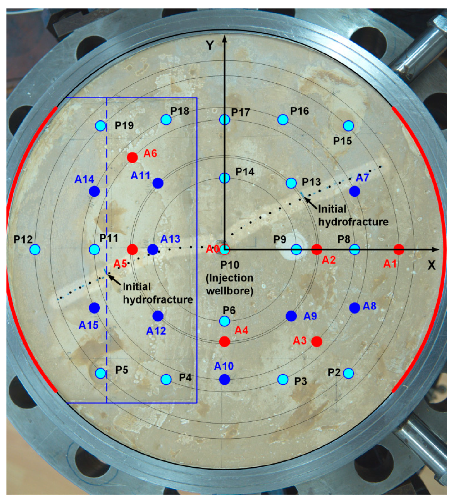
Before the sample creation, a brass tube with a diameter of 12 mm was inserted into the central hole of the lower disc simulating a cased borehole. The tube upper end was plugged. In the middle of tube, a slot was made with a rectangular initiator made of two layers of brass mesh with a cell size of 0.3 mm. A height of the initiator was 10 mm and a length 12 mm. The initiator was oriented along the X-axis of the sample towards the existing fracture in the sample. A schematic representation of the sample in the experimental setup is shown in Figure 4. Figure 5 shows the positions of ultrasonic transducers, pore pressure measurement points, and lateral loading chambers. Two supplemental wells were located at points P5 and P15, they were used to vacuumize and saturate the sample with a fluid. In the experiment, a low-viscosity organosilicon liquid with a dynamic viscosity of 5 mPa·s and a density of 918 kg/m3 was used as a pore fluid.
The same pumping system was used as in the calibration experiment to carry out hydraulic fracturing and maintain a given constant pressure in the lateral loading chambers. The fluid was pumped into the central well with a constant flow rate to create a hydraulic fracture. For this purpose, an organosilicon liquid with a dynamic viscosity of 0.2 Pa·s was used. The pressure in the working well and the vertical pressure and pressure in the side chambers were measured using pressure transducers NAT-8252 manufactured by Trafag AG. The identical transducers were used to measure the pore pressure at the points shown in Figure 5. The signals from the pressure sensors were recorded using two low-speed ADCs with a sampling frequency of 1000 Hz.
For active acoustic monitoring during the opening of both a hydraulic fracture and a natural fracture, the piezoelectric transducers A5 and A6 were used as emitters in the upper disc, the piezoelectric transducers A11, A12, A13 and A15 located at the lower disc served as receivers. The resonant frequency of the piezoelectric transducers was approximately 250 kHz, as in the preliminary experiments. The repetition period of ultrasonic pulses was 100 ms, and the delay between them was set to 2 ms, which, on the one hand, made it possible to avoid overlapping signals from different emitters, and on the other, made it possible to synchronize the entire set of received signals. The system of generation and registration of ultrasonic pulses was the same as in the calibration experiment described above.
Registering the amplitude of the ultrasonic pulses passed through the fracture, it was possible to estimate the value of its opening. At first, individual pulses were extracted from the ADC recording, and the maximums of their amplitudes were found. Then, the found values were normalized by the average value of the pulse record envelopes at the beginning of the recording. Finally, using normalized values, the fracture opening value was calculated based on the results of calibration experiments.
3. Conducting and Results of Experiments
3.1. Calibration experiments
It was necessary to fulfill the condition of exceeding the radial compressive stress over the vertical one to ensure that a horizontal hydraulic fracture was obtained, so that the vertical axis of the sample is perpendicular to the plane of the fracture. Four worm clamps were used to set the required amount of radial stress. The radial stress was estimated based on measuring the diameter of the free part of the sample before and after screed clamps. The elasticity modulus of the model material was 2 GPa, it was measured in specially conducted deformation tests. The change in the diameter of the sample during clamp screeds was ≈20 microns, which corresponded to a radial stress of ≈0.5 MPa. It exceeded the vertical compressive stress of 0.37 MPa, corresponding to the minimum possible pressure maintained by the pumping unit in the hydraulic press. Thus, the condition of horizontal stress excess over vertical was fulfilled, which made it possible to obtain a horizontal hydraulic fracture in the experiment.
During the experiment, the sample was first loaded with vertical pressure. Then, after a constant level of vertical load was reached, data collection on a high-speed ADC and movement registration were started synchronously. Approximately 5 seconds after that, the supply of silicone liquid into the working well was switched on with an initial flow rate of 5 cm3/min. After that, the pressure in the working well began to increase until the moment of the hydraulic fracture formation. After the fracture was formed, the pressure in the well dropped sharply to a certain level and then slowly increased. Then, without stopping the supply of fracturing fluid into the well, its flow rate was gradually increased up to values 7.5, 12, 18, 24, 30, 40 and 50 cm3/min. A new equilibrium value of fracture opening was established at each new flow rate because the vertical pressure was maintained constant. At the same time, the pressure of the fluid entering the well increased slightly. The continuous fluid pumping in did not allow the fracture to close.
The formation and growth of a hydraulic fracture occur unevenly in different directions due to various random factors, for example, variations in the strength and permeability of the sample, so the size of the fracture opening turns out to be different at different points of its surface. It can be assumed that the fracture boundaries form a plane inclined relatively to the base horizon, if we ignore the deformations of the sample. Since the coordinates of the ultrasound emitters and receivers did not coincide with the coordinates of the displacement meters, the equation of the fracture plane was found by using the displacement data and it was used to calculate the fracture aperture at the points of the acoustic transducer locations of by the least squares method.
A threshold criterion was used to discriminate the probing ultrasonic pulses, considering a given period of their repetition, which made it possible to compensate for errors in the sampling frequencies of the ADC and the pulse repetition period. After that, using the Hilbert transformation, the analytical envelope of each selected pulse was constructed. The maximum value of the envelope of the first 4...5 pulse periods was taken as the pulse amplitude to avoid interference distortions caused by reflections from the elements of the experimental installation. As a result of such processing, the dependence of the pulse amplitude on time was obtained. Time-synchronized recordings of the pressure in the well, the width of the hydraulic fracture, and the amplitude of the transmitted ultrasonic pulse normalized to its value before the hydraulic fracturing are shown in Figure 6.
To compare the ultrasonic pulse amplitudes with the fracture opening value, piecewise linear interpolation of the displacement dependence on time was carried out, followed by their recalculation to the time corresponding to the pulse repetition period. Then, according to the obtained values, the dependence of the amplitude of the ultrasonic pulses passed through the hydraulic fracture on the fracture opening value was obtained. This dependence is shown in Figure 7. An exponential relation was used to approximate it, where A is the amplitude of the ultrasonic pulse, normalized by its amplitude at a fracture width w = 20 microns. The attenuation coefficient was γ ≈ 8 cm-1, and the multiplier a = 1.03. Note that the previously obtained results [20] relate to the direct incidence of the acoustic wave on the fracture. The angles of ultrasonic waves incidence on the fracture in both calibration and main experiments are approximately the same, which makes it possible to use the obtained calibration dependence in the main experiment.
3.2. Main Experiment
After performing the preparatory procedures and establishing the vertical pressure and pressure in the lateral loading chamber along the horizontal X axis of the installation, the hydraulic fracturing fluid was injected into the central well with a constant flow rate of 5 cm3/min. The vertical pressure was maintained at 6 MPa, and the pressure in the chambers along the X-axis was 1.3 MPa. Figure 8 shows the first 300 seconds of pressure recording in the central well and in the vicinity of a natural fracture in the sample. The pressure increase in the central well lasted approximately 56 seconds. The maximum pressure was 8.5 MPa, this value can be assumed to be equal to the hydraulic fracturing pressure. After the injection pressure drop, the growth of pore pressures in the vicinity of the natural fracture begins. The almost simultaneous onset and close rates of these pressure increases at different points should be noted.
After the initial hydraulic fracturing, the upper cover of the experimental installation was removed to check the hydraulic fracture position. A photo of the sample in an open experimental setup with the locations of the pore pressure measurement points, acoustic emission receivers, and the place of the insert is shown in Figure 9.
Even though the fracture initiator was asymmetrical and directed the “natural” fracture (to the left in the photos), two wings of the hydraulic fracture were formed. The left wing of the fracture in the initial section is directed along the X-axis in accordance with the initiator direction, after that the fracture deviates from the original direction. This deviation is most likely caused by the peculiarities of the stress field related with the presence of the “natural” fracture in the sample. Also, as can be seen in Figure 9, the left branch of the fracture crossed the “natural” fracture, while its trajectory visible on the surface reached the lower edge of this boundary. The right branch of the fracture was formed without initiator, most likely due to the flow of fracturing fluid along the outer surface of the casing of the central well. The direction of its growth was determined only by the peculiarities of the stress field in the vicinity of the well.
Considering the mutual location of the hydraulic fracture, the “natural” fracture, the emitters and receivers of ultrasound, at the next stage of the experiment on re–opening of the hydraulic fracture, pairs of "emitter-receiver" were selected. The selection criterion was the intersection of either the hydraulic fracture or the “natural” fracture by the "emitter–receiver" line. Thus, for the A5 and A6 emitters located in the upper disc, the receivers were A11, A12, A13 and A15, located at the base disc of the installation. The reliable results were obtained only for 5 pairs: A5-A11, A5-A12, A5-A13, A5-A15 and A6-A11.
Experiments on the re-opening of the hydraulic fracture were carried out at the same injection flow rate of 10 cm3/min. Four experiments were conducted. The results of these experiments generally repeat each other, so the following are the results of one of them. Figure 10 shows the dependence of the pressure in the injection well, the pore pressure at point P11, located near the end of the hydraulic fracture, and the magnitude of the fracture opening on time. Note that the dependence of the fracture opening on time is very noisy despite the treatment with a smoothing filter.
It can be seen that both the fracture opening and the pressure in the vicinity of the measurement point P11 begin to change after the maximum pressure in the injection well is reached. A slight pressure drop may be caused by the influx of pore fluid from the surrounding massif into the expanding fracture. The lag of the fluid front from the fracture tip (a lag) was also observed earlier in the experiments conducted at the described installation [21]. After reaching the maximum fracture opening, its value is at an approximately constant level and begins to decrease after stopping the injection.
The pressures and the opening values behave in a similar way at the measuring points located along the lower boundary of the “natural” fracture. These variations are presented in Figure 11. The pressures for lines A5-A11 and A6-A11 were calculated by interpolation in projections of the intersection points of these lines with the plane of the “natural” fracture on its lower boundary (dotted line in Figure 5). For the A5-A13 route, the pressure at point P11 was used. Point P19 on the graph is given for reference.
The pressure change along the entire lower boundary of the “natural” fracture begins simultaneously with the maximum pressure in the injection well and is accompanied by a slight pressure drop. Then, a smooth increase in pressure begins at all the points, but at points more distant from the hydraulic fracture the growth is slower. This pressure behavior indicates an unsteady flow in the fracture due to both its expansion and the filtration of fluid into the surrounding material. The increase in the opening of the “natural” fracture at points A5-13 and A5-11, closest to the hydraulic fracture, at first occurs abruptly and then gradually increases as the pressure increases. The opening is maximal at the intersection point of the hydraulic fracture and the “natural” fracture. At more distant points, the opening decreases rapidly with distance. After stopping the injection, the “natural” fracture is closed. This fracture closes most quickly at the intersection with the hydraulic fracture. As the pressures equalize along the fracture length, the fracture width also equalizes. Negative width values are an artifact and may be associated with an increase in the contact density of the fracture boundaries due to the influence of external vertical pressure. Attention may be drawn to the abnormal increase in the width of the fracture on the A5-12 highway after stopping the injection. Perhaps this is because this route intersects both the hydraulic fracture and the “natural” one, which leads to their joint influence on the amplitude of the ultrasonic pulse.
The dependence of the width of natural fracture on time and distance from the area of the intersection of “natural” fracture and hydraulic fracture is shown in Figure 12.
After conducting four experiments on re-opening the hydraulic fracture, the experimental installation was opened for a visual assessment of the possible further propagation of fractures during repeated injections. A photo of the vertical view of the experimental unit is shown in Figure 13. As we can see, both hydraulic fracture's branches have increased their length. At the same time, the change in the length of the wright branch is noticeably more significant. The wright branch extended by 81 mm, while the left one by 54 mm. This fact may indicate that the presence of the “natural” fracture in the path of the left branch prevented its growth. The reason for this is the leakage of the fracturing fluid from the hydraulic fracture into the “natural” fracture. For further estimates, it is essential to know the lengths of both branches of fractures. We will assume that in each of the four experiments, there was an equal increase in the length of the fractures by one-fourth of their final extension.
4. Discussion
To assess the reliability of the experiment results, it is advisable to compare the data on the fracture aperture with the volume of the injected fluid. Let us consider the entire system of fractures as consisted of three parts and separately estimate the volume of each of them.
First, let us estimate the volume of the wright fracture branch, that has gone in the direction, opposite the direction of the “natural” fracture. We use the results presented in [22]. The width of the fracture at the wellbore wall ww is calculated based on:
where:
pw – pressure in the wellbore,
G – shear modulus,
– Poisson ratio,
L – fracture length,
– minimum horizontal stress.
Based on the conditions of our experiments, we can assume that = 0. The pressure in the wellbore was determined at the time of stopping the injection and was 4.8 MPa. For the model material, the shear modulus G = 1 GPa, the Poisson ratio = 0.2. The length of the wright fracture measured on the surface L = 100 mm. The fracture width at the wellbore wall is estimated as ww = 0.7 mm.
The volume of the left wing of the fracture is calculated as , where h is the fracture height equal to the height of the sample 72 mm. According to the calculations, we obtained Vw ≈ 3.6 ml.
When calculating the volume of the left branch of the fracture, we assume its width at the wellbore is the same as for the wright fracture. Its measured length is 120 mm. For the width of the fracture at its end, we took the width measured on the A5-15 line equal to 0.48 mm. Let us assume that the longitudinal section of the fracture is a trapezoid with the bases mentioned above and a height equal to the length of the fracture. Then, with a sample thickness of 72 mm, the volume of the left branch of the fracture Ve ≈ 4.9 ml.
The volume of the “natural” fracture VNF, calculated based on the measurements, is 4.1 ml. Thus, the total volume of the fracture system at the end of injection ml. The injected fluid volume at a 10 ml/min flow rate was 11.4 ml. Both the calculated and the actual volume values agree with each other. A slight overestimation of the total fracture volume may be associated with a rough approximation of the fracture profile due to insufficient measuring points.
The existing discrepancy cannot be caused by fluid leakoff from fractures into the surrounding pore formation. However, an estimation of the leakoff will also be useful. To do this, we use the following formula for the viscous leakoff coefficient Cv [23]:
where k – permeability, – porosity, – pressure drop and – viscosity. Substituting , , and we get . Substituting this coefficient into the formula , considering the total fracture surface area, during injection time t = 69 s, gives the estimate of the leakoff volume V = 0.06 ml, which is two orders of magnitude smaller than the injected volume. Thus, under the conditions of the conducted experiments, the hydraulic fracturing fluid leakoff from the fracture into the surrounding formation can be ignored due to their smallness.
5. Conclusions
A method for producing samples containing artificial interfaces was developed to conduct experiments on the interaction of a hydraulic fracture with “natural” fractures existing in the sample. It is assumed that this technique can be used to produce samples containing multiple inhomogeneities that differ in composition from the primary sample and have different interface properties.
Ultrasonic monitoring of both hydraulic fracture and natural fractures in the model sample based on attenuation of ultrasonic pulses passing through them, supplemented by the results of preliminary conducted calibration experiments, allowed us to estimate the hydraulic fracture and natural fracture width at several points during repeated injections.
The experiment shows that the natural fracture limits hydraulic fracture propagation. This is caused by hydraulic fracturing fluid leaks into a natural fracture. Both fractures form a single hydraulic system that reacts almost simultaneously to the reopening of the hydraulic fracture, but the degree of response decreases with the total distance from the injection wellbore. This manifests in the dependencies of changes in pressure and fracture opening on time at different distances.
Author Contributions
Conceptualization, S.B.T. and E.V.Z.; methodology, E.V.Z.; software, E.V.Z.; formal analysis, E.V.Z. and T.K.C.; investigation, E.V.Z., P.E.Z. and T.K.C.; resources, E.V.Z., P.E.Z.; data curation, E.V.Z., and T.K.C.; writing—original draft preparation, E.V.Z.; writing—review and editing, V.A.N. and P.E.Z.; visualization, E.V.Z.; supervision, S.B.T.; project administration, S.B.T.; funding acquisition, S.B.T. All authors have read and agreed to the published version of the manuscript.
Funding
This research was funded by Russian Science Foundation grant number No 22-27-00643.
Data Availability Statement
The data presented in this study are available on request from the corresponding author.
Conflicts of Interest
The authors declare no conflict of interest.
References
- Economides, M.J.; Boney, C. Reservoir Stimulation in Petroleum Production. In Reservoir stimulation 3rd edition; Economides M. J., Nolte K. G. Eds.; Wiley; 2000.
- Hattori, G.; et al. Numerical Simulation of Fracking in Shale Rocks: Current State and Future Approaches. Arch. Comput. Methods Eng. 2017, 24, 281–317. [Google Scholar] [CrossRef] [PubMed]
- Baykin, A.N.; Golovin, S.V. Application of the fully coupled planar 3D poroelastic hydraulic fracturing model to the analysis of the permeability contrast impact on fracture propagation. Rock Mech. Rock Eng. 2018, 51, 3205–3217. [Google Scholar] [CrossRef]
- Berchenko, I.; Detournay, E. Deviation of Hydraulic Fractures through Poroelastic Stress Changes Induced by Fluid Injection and Pumping. Int. J. Rock Mech. Min. Sci. 1997, 34, 1009–1019. [Google Scholar] [CrossRef]
- Gladkov, I.O.; Linkov, A.M. Solution of a Plane Hydrofracture Problem with Stress Contrast. J. Appl. Mech. Tech. Phys. 2018, 59, 341–351. [Google Scholar] [CrossRef]
- Smirnov, V.B.; et al. Fluid Initiation of Fracture in Dry and Water Saturated Rocks. Izv. Phys. Solid Earth 2020, 56, 808–826. [Google Scholar] [CrossRef]
- Stanchits, S.; et al. Acoustic Emission and Ultrasonic Transmission Monitoring of Hydraulic Fracture Propagation in Heterogeneous Rock Samples. 30th European Conference on Acoustic Emission Testing & 7th International Conference on Acoustic Emission, University of Granada; OnePetro, 2012.
- Zoback, M.D.; et al. Laboratory hydraulic fracturing experiments in intact and pre-fractured rock. Int. J. Rock Mech. Min. Sci. Geomech. Abstr. 1977, 14, 49–58. [Google Scholar] [CrossRef]
- de Pater, C.J.; et al. Experimental verification of dimensional analysis for hydraulic fracturing. SPE Production & Facilities. OnePetro. [CrossRef]
- Lu, G.; Momeni, S.; Lecampion, B. Experimental Investigation of Hydraulic Fracture Growth in an Anisotropic Rock with Pre-Existing Discontinuities Under Different Propagation Regimes. 56th U.S. Rock Mechanics/Geomechanics Symposium, Santa Fe, New Mexico, USA, June 2022; ARMA-2022-0239. [CrossRef]
- Oye, V.; Stanchits, S.; Babarinde, O.; et al. Cubic-meter scale laboratory fault re-activation experiments to improve the understanding of induced seismicity risks. Sci Rep 2022, 12, 8015. [Google Scholar] [CrossRef] [PubMed]
- Turuntaev, S.B.; et al. Hydraulic Crack Growth Dynamics from Ultrasound Transmission Monitoring in Laboratory Experiments. Izv. Phys. Solid Earth 2021, 57, 671–685. [Google Scholar] [CrossRef]
- Borisov, V.E.; et al. Numerical Simulation of Laboratory Experiments on the Analysis of Filtration Flows in Poroelastic Media. Her. Bauman Mosc. State Tech. Univ. Ser. Nat. Sci. 2020, 1, 16–31. [Google Scholar] [CrossRef]
- Trimonova, M.; et al. The Study of the Unstable Fracture Propagation in the Injection Well: Numerical and Laboratory Modelling. SPE Russian Petroleum Technology Conference; OnePetro, 2017. [CrossRef]
- Turuntaev, S.B.; et al. An Influence of Pore Pressure Gradient on Hydraulic Fracture Propagation. 9th Australasian Congress on Applied Mechanics (ACAM9); Engineers Australia, 2017, 712–723.
- Medlin, W.L.; Massé, L. Laboratory Experiments in Fracture Propagation. SPE 1984, 256–268. [Google Scholar] [CrossRef]
- Groenenboom, J.; Fokkema, J.T. Monitoring the width of hydraulic fractures. Geophysics 1998, 63, 139–140. [Google Scholar] [CrossRef]
- Groenenboom, J.; van Dam, D.B.; de Pater, C.J. Time-Lapse Ultrasonic Measurements of Laboratory Hydraulic-Fracture Growth: Tip Behavior and Width Profile. SPE J. 2001, 14–24. [Google Scholar] [CrossRef]
- Liu, D.; Lecampion, B.; Blum, T. Time-lapse reconstruction of the fracture front from diffracted waves arrivals in laboratory hydraulic fracture experiments. Geophys. J. Int. 2020, 223, 180–196. [Google Scholar] [CrossRef]
- Zenchenko, E.V.; et al. Concurrent Active Acoustic and Deformation Monitoring of a Hydraulic Fracture in Laboratory Experiments. Izv. Phys. Solid Earth 2023, 59, 468–476. [Google Scholar] [CrossRef]
- Trimonova, M.A.; et al. Experimental confirmation of the existence of the lag in the hydraulic fracture. Springer Ser. Geomech. Geoengin. 2020, 1934–1942. [Google Scholar] [CrossRef]
- Geertsma, J.; de Klerk, F. A Rapid Method of Predicting Width and Extent of Hydraulically Induced Fractures. JPT 1969, 1571–1581. [Google Scholar] [CrossRef]
- Mack, M.G; Warpinski, N.R. Mechanics of Hydraulic Fracturing. In Reservoir stimulation 3rd edition; Economides M. J., Nolte K. G. Eds.; Wiley; 2000.
Figure 1.
Diagram of experimental installation for studying the passage of ultrasound through a hydraulic fracture in calibration experiments.
Figure 1.
Diagram of experimental installation for studying the passage of ultrasound through a hydraulic fracture in calibration experiments.
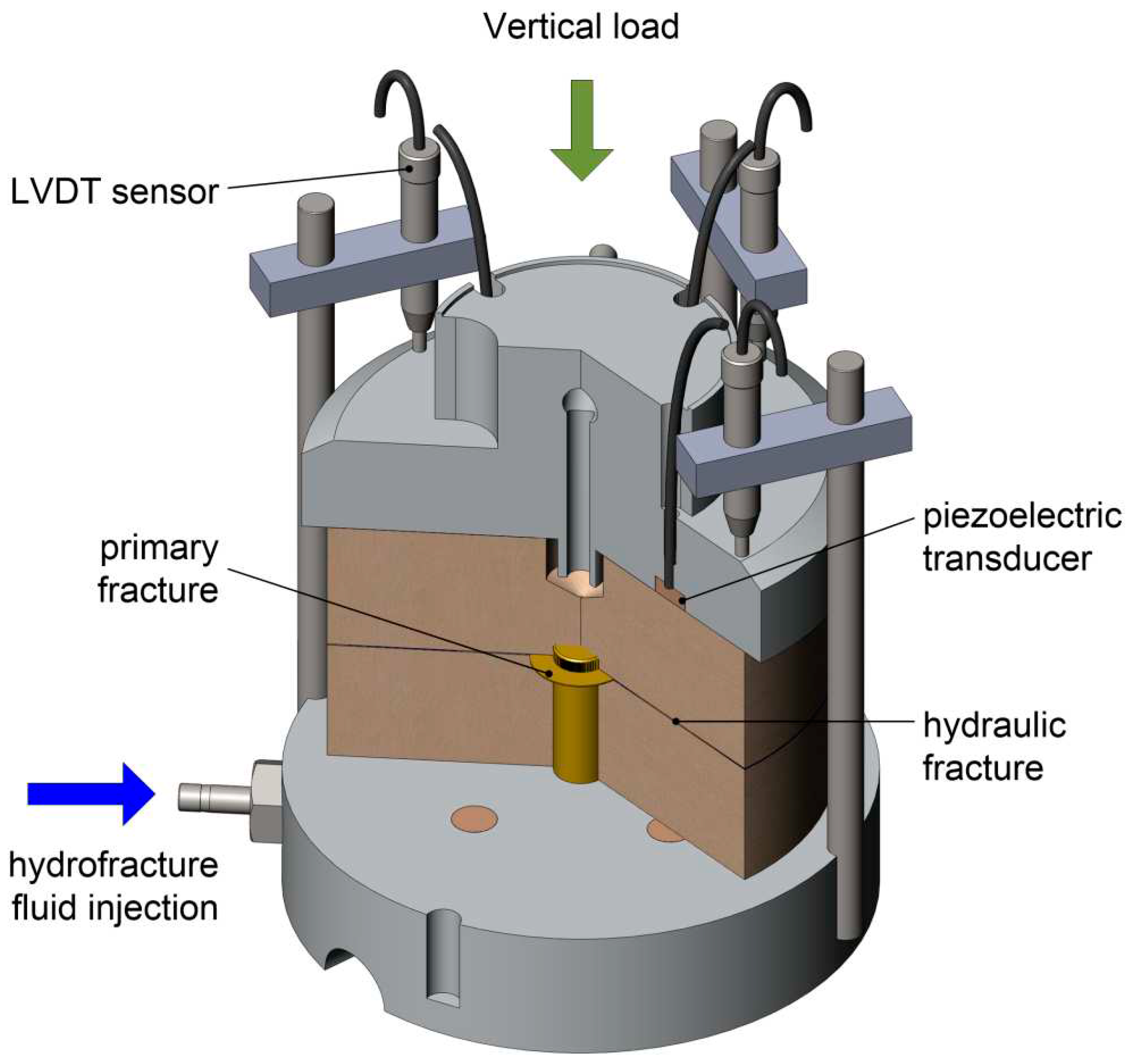
Figure 2.
The scheme of the main experimental installation.
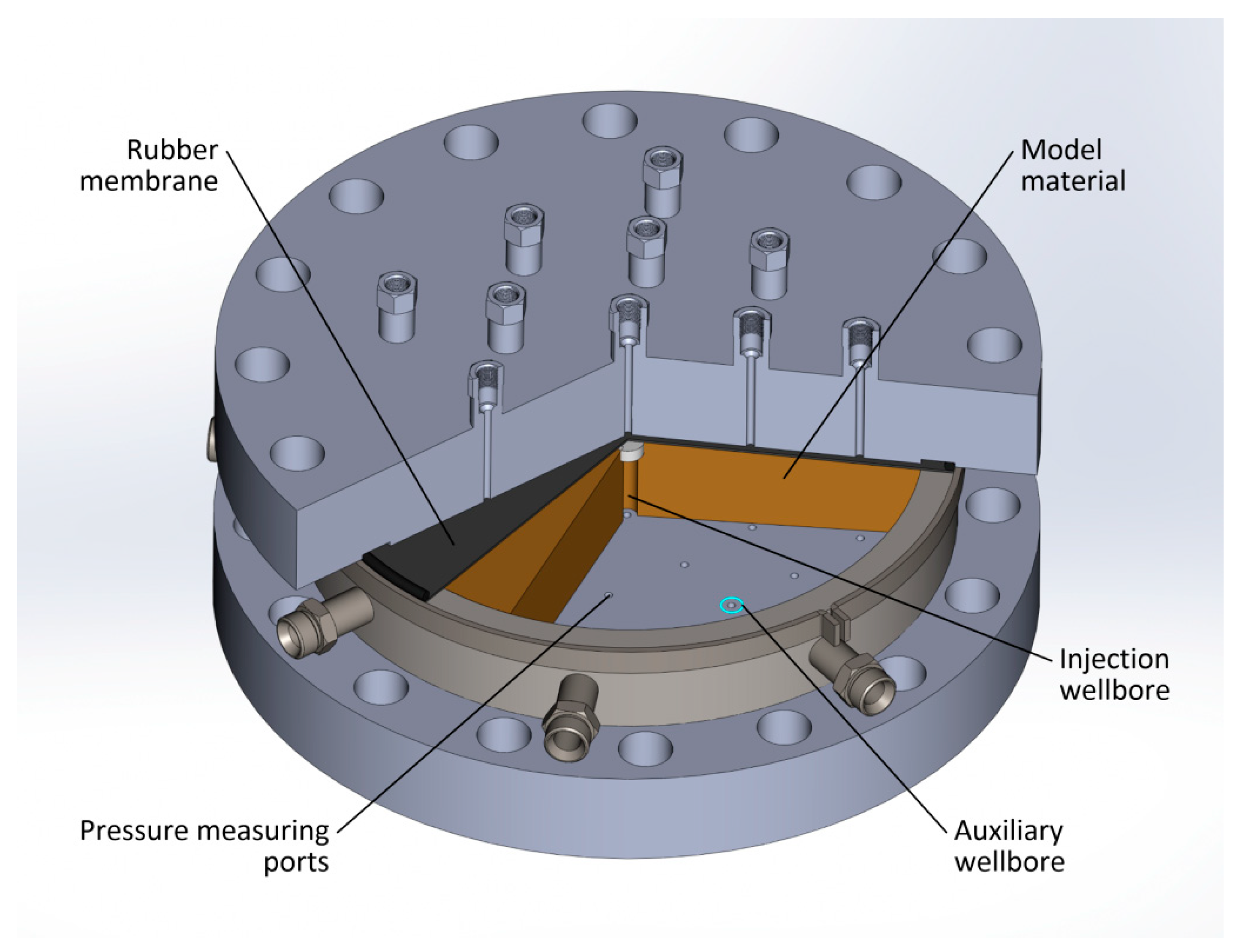
Figure 3.
A polymethylmethacrylate insert is placed in the sample at the first stage of its filling.
Figure 3.
A polymethylmethacrylate insert is placed in the sample at the first stage of its filling.
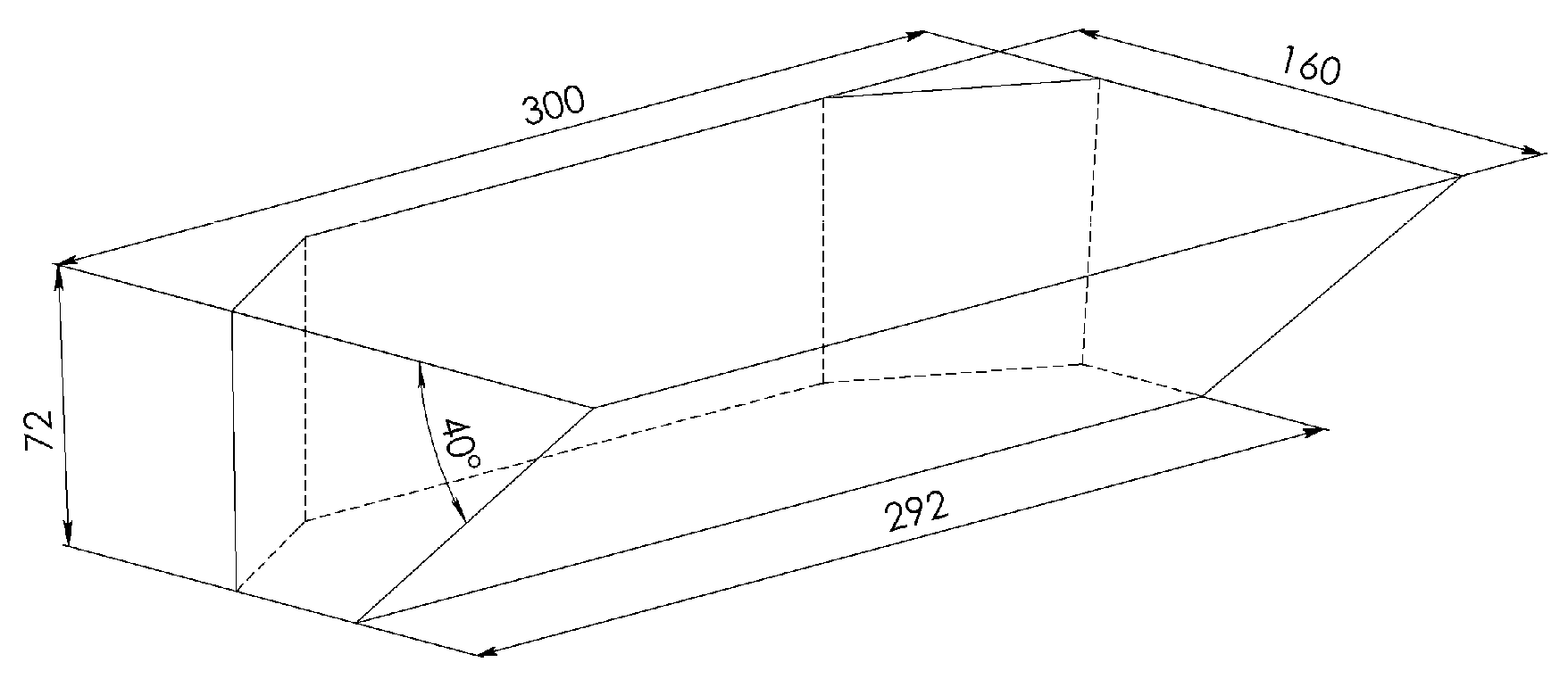
Figure 4.
Schematic representation of the sample in the installation. The central well from which hydraulic fracturing was carried out is not shown.
Figure 4.
Schematic representation of the sample in the installation. The central well from which hydraulic fracturing was carried out is not shown.
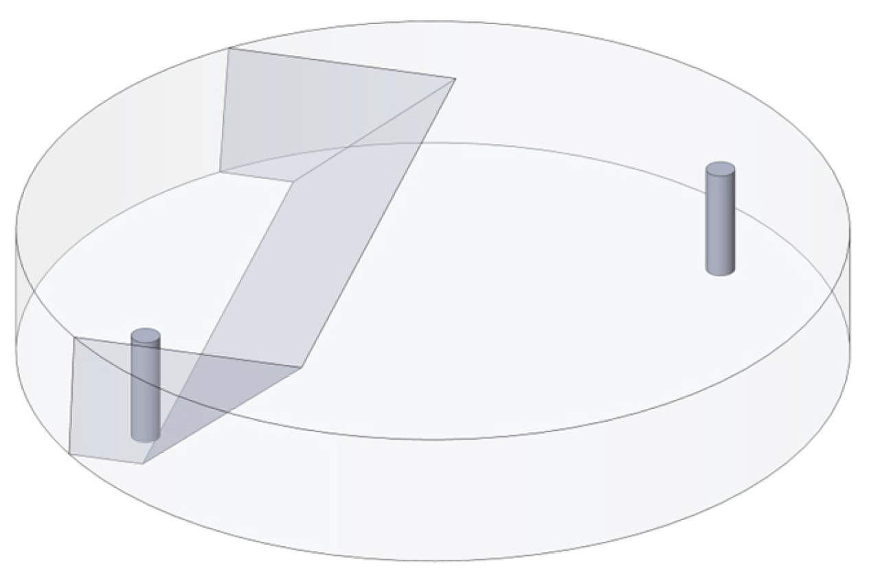
Figure 5.
The layout of ultrasonic transducers, pore pressure measurement points and lateral loading chambers in the experimental setup. The red circles are piezoelectric transducers in the upper disk, the blue ones are in the lower one. Blue circles are pore pressure measurement points. The blue outline shows the boundaries in the insert.
Figure 5.
The layout of ultrasonic transducers, pore pressure measurement points and lateral loading chambers in the experimental setup. The red circles are piezoelectric transducers in the upper disk, the blue ones are in the lower one. Blue circles are pore pressure measurement points. The blue outline shows the boundaries in the insert.
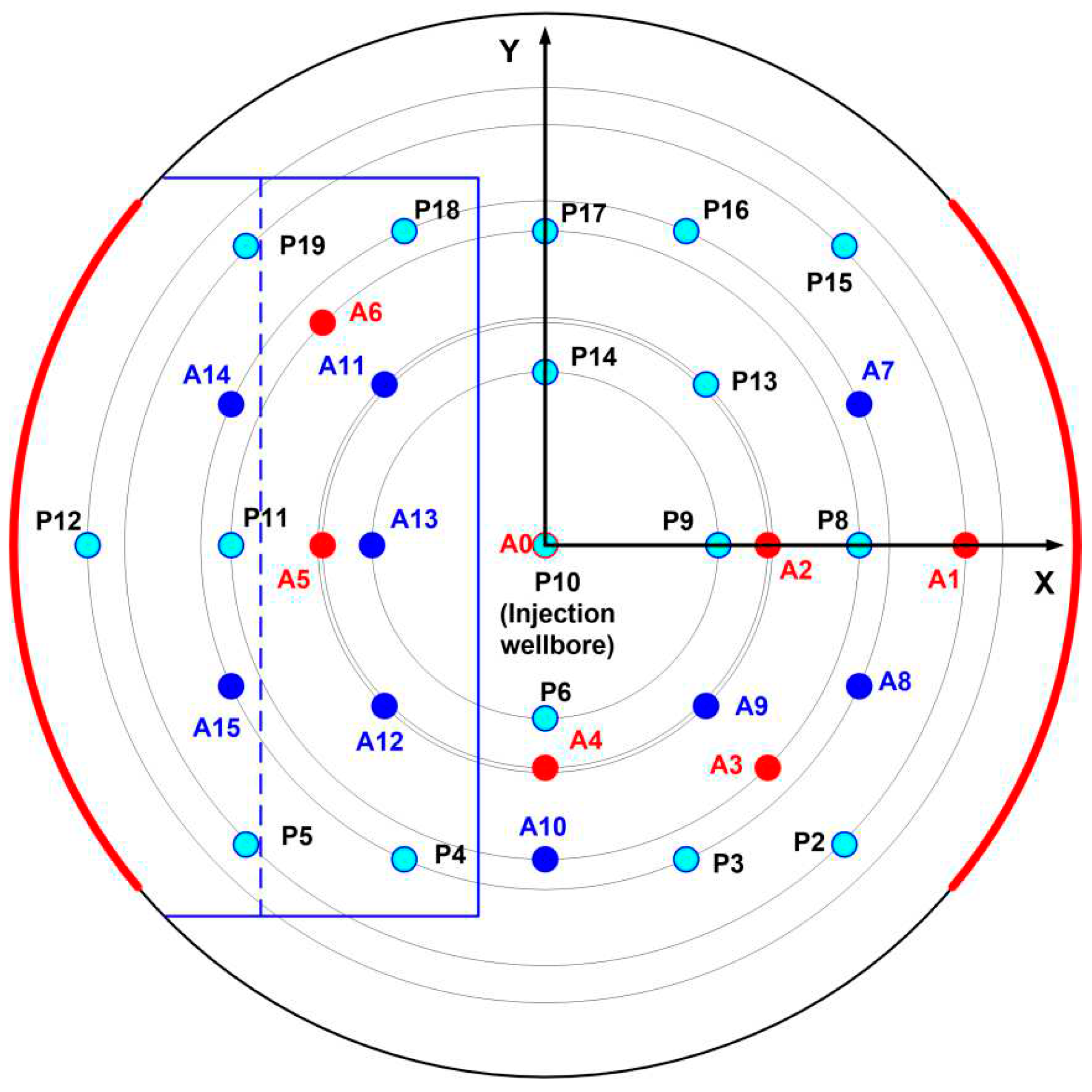
Figure 6.
Time-synchronized recordings of the pressure in the well, the width of the hydraulic fracture, and the amplitude of the transmitted ultrasonic pulse normalized to its value before the hydraulic fracturing. The numbers above the successive sections of the pressure curve show the corresponding flow rate of the fracturing fluid in cm3/min.
Figure 6.
Time-synchronized recordings of the pressure in the well, the width of the hydraulic fracture, and the amplitude of the transmitted ultrasonic pulse normalized to its value before the hydraulic fracturing. The numbers above the successive sections of the pressure curve show the corresponding flow rate of the fracturing fluid in cm3/min.
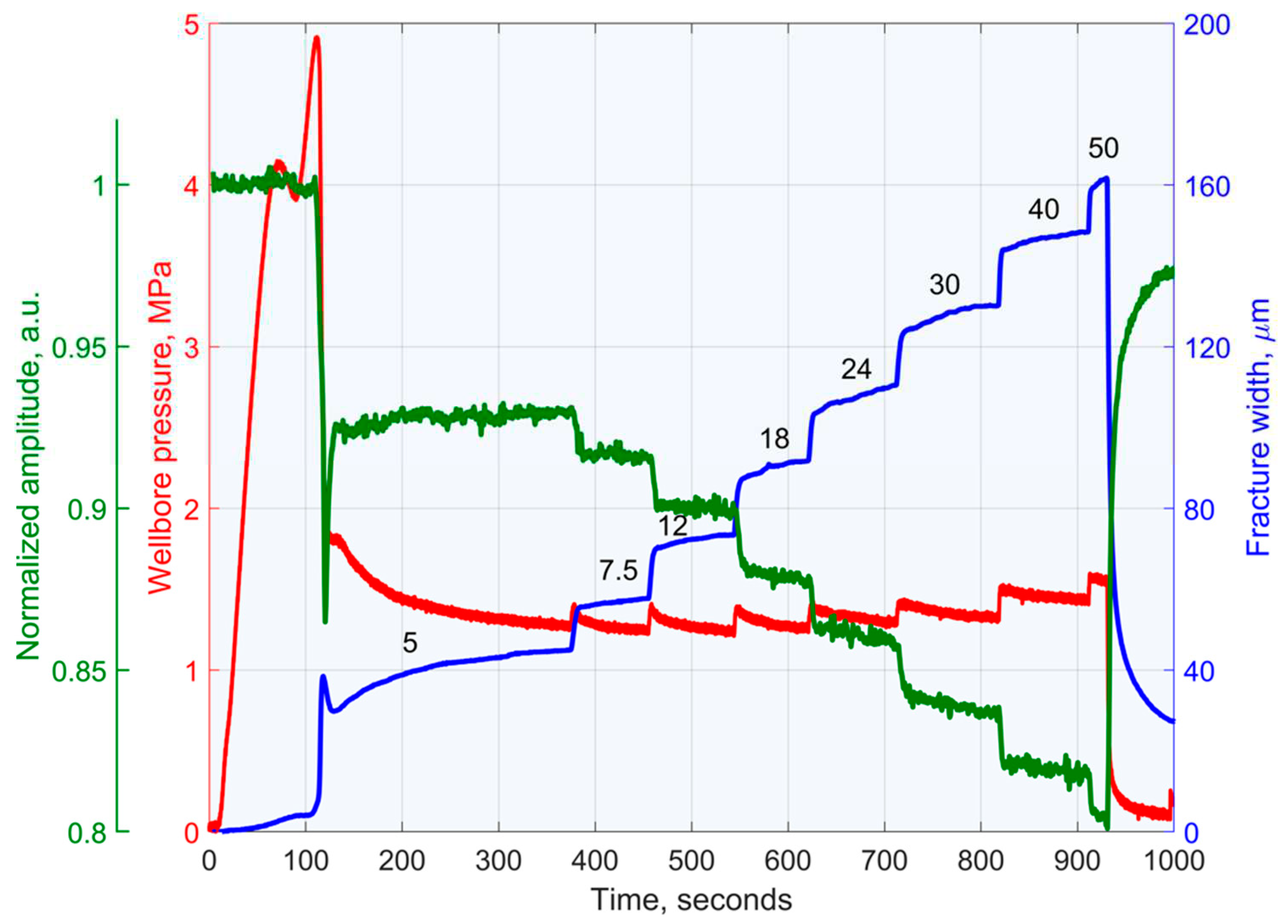
Figure 7.
The dependence of the amplitude of the ultrasonic pulse passing through the hydraulic fracture on its width. The amplitude is normalized to its value at a width of 20 microns.
Figure 7.
The dependence of the amplitude of the ultrasonic pulse passing through the hydraulic fracture on its width. The amplitude is normalized to its value at a width of 20 microns.
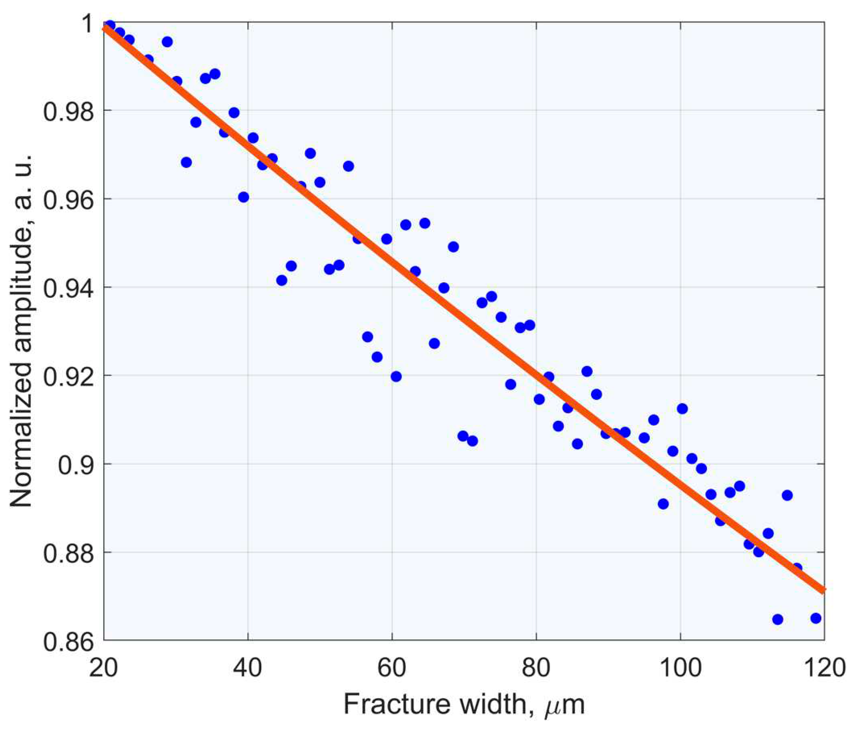
Figure 8.
The variation of the pressure in the central well and at points near the artificial fracture in time during hydraulic fracturing.
Figure 8.
The variation of the pressure in the central well and at points near the artificial fracture in time during hydraulic fracturing.
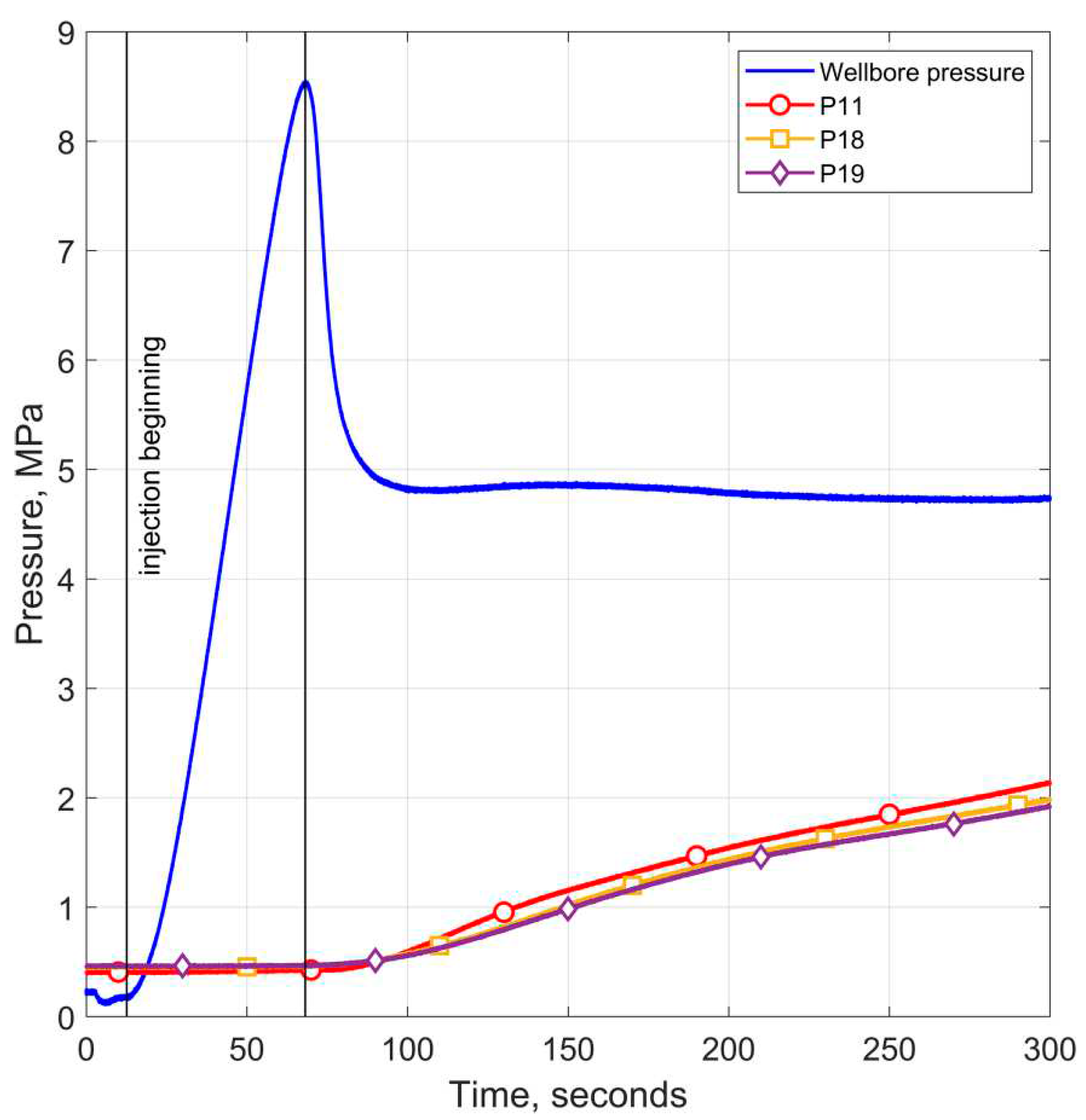
Figure 9.
The photo of the sample after hydraulic fracturing. The highlighted areas show the hydraulic fracture trajectory marked by points.
Figure 9.
The photo of the sample after hydraulic fracturing. The highlighted areas show the hydraulic fracture trajectory marked by points.
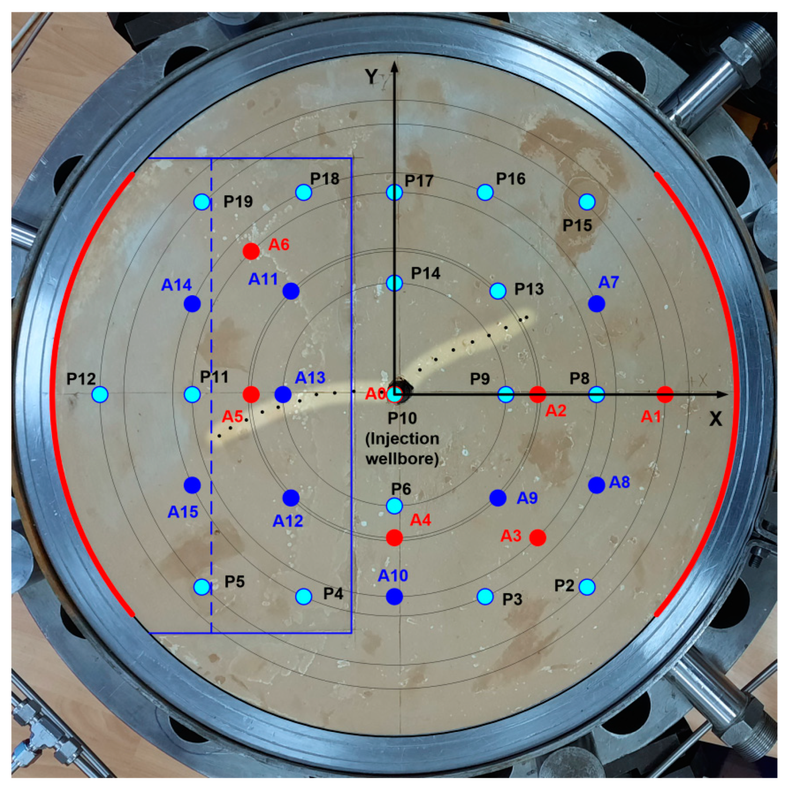
Figure 10.
The dependence of the pressure in the injection well, the pore pressure at point P11, and the value of the fracture opening on the A5-A15 line on time.
Figure 10.
The dependence of the pressure in the injection well, the pore pressure at point P11, and the value of the fracture opening on the A5-A15 line on time.
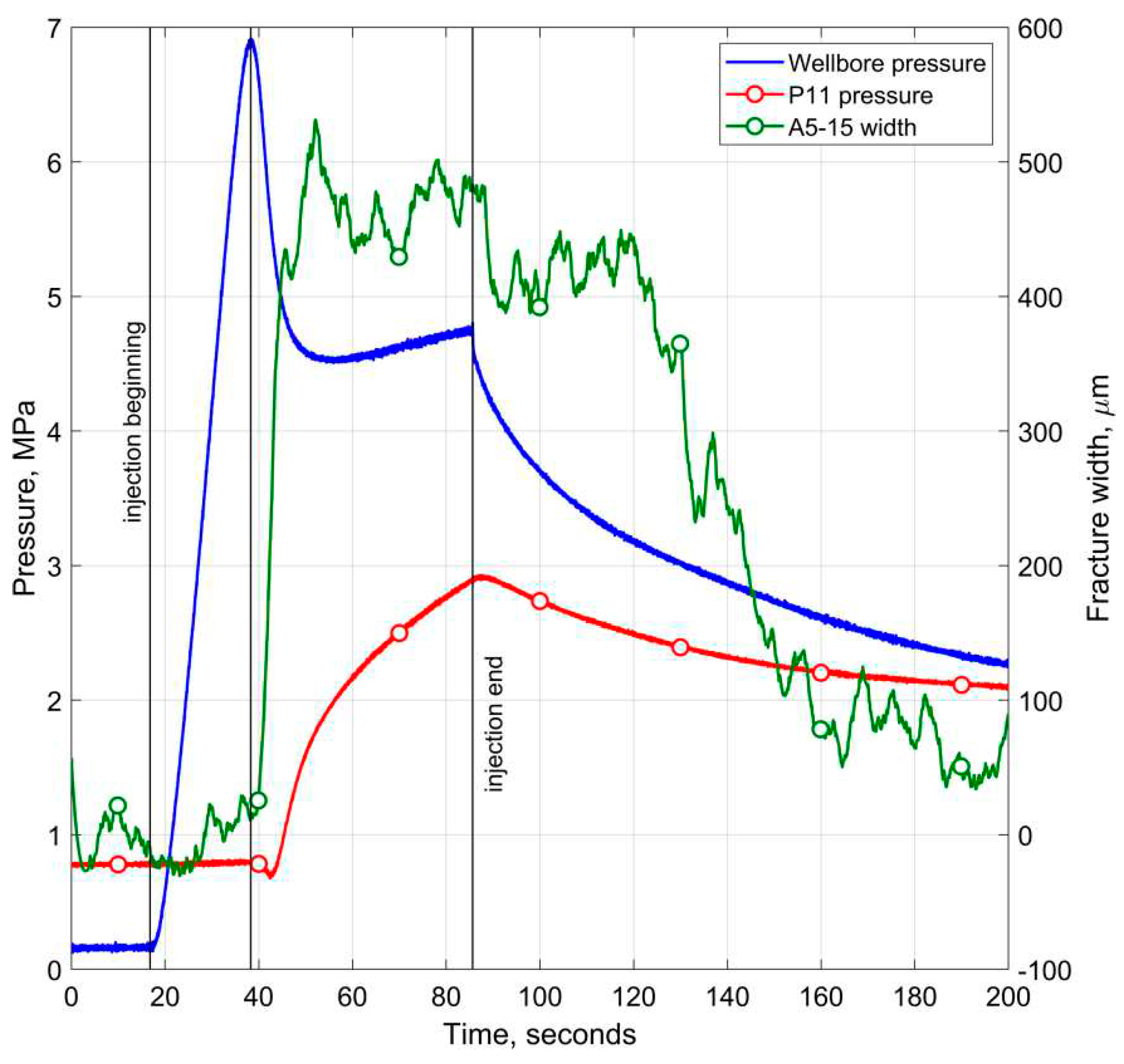
Figure 11.
Dependences of pressures in the injection well, as well as pressures and fracture aperture along the “natural” fracture in the sample on time.
Figure 11.
Dependences of pressures in the injection well, as well as pressures and fracture aperture along the “natural” fracture in the sample on time.
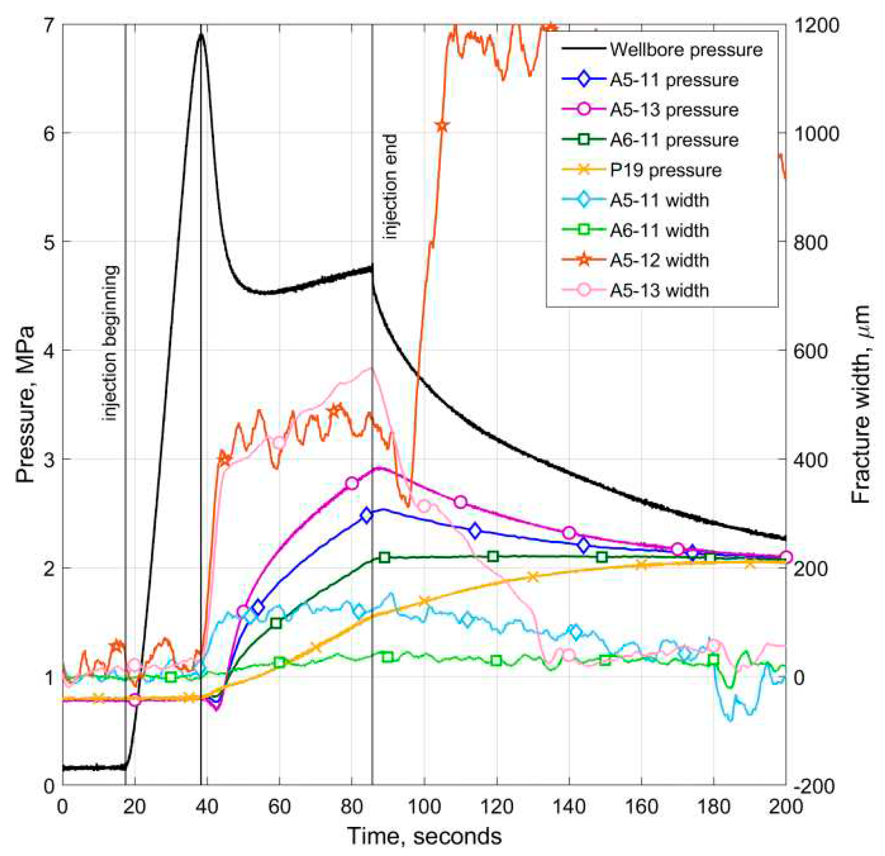
Figure 12.
The dependence of the width of natural fracture on time and distance from the area of the intersection of “natural” fracture and hydraulic fracture.
Figure 12.
The dependence of the width of natural fracture on time and distance from the area of the intersection of “natural” fracture and hydraulic fracture.
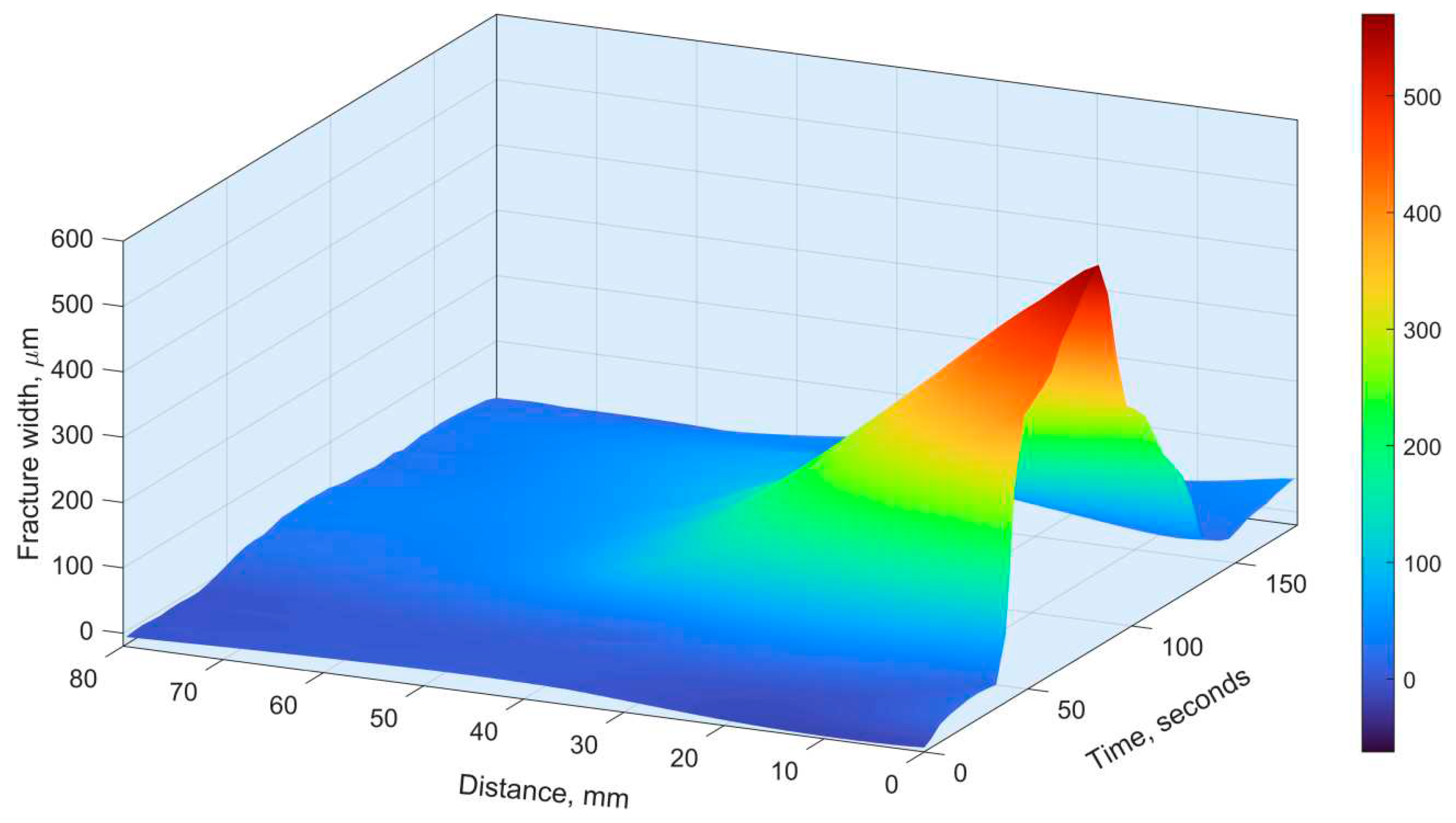
Figure 13.
Photo of the upper surface of the sample after conducting a series of experiments on hydrofracture reopening. Black dots in highlighted regions denote hydrofracture trajectory. Arrows show the position of the fracture after the initial hydraulic fracturing.
Figure 13.
Photo of the upper surface of the sample after conducting a series of experiments on hydrofracture reopening. Black dots in highlighted regions denote hydrofracture trajectory. Arrows show the position of the fracture after the initial hydraulic fracturing.
Disclaimer/Publisher’s Note: The statements, opinions and data contained in all publications are solely those of the individual author(s) and contributor(s) and not of MDPI and/or the editor(s). MDPI and/or the editor(s) disclaim responsibility for any injury to people or property resulting from any ideas, methods, instructions or products referred to in the content. |
© 2023 by the authors. Licensee MDPI, Basel, Switzerland. This article is an open access article distributed under the terms and conditions of the Creative Commons Attribution (CC BY) license (http://creativecommons.org/licenses/by/4.0/).
Copyright: This open access article is published under a Creative Commons CC BY 4.0 license, which permit the free download, distribution, and reuse, provided that the author and preprint are cited in any reuse.


