
Submitted:
05 December 2023
Posted:
07 December 2023
You are already at the latest version
Abstract
There are two basic methods for radial external load distribution calculation on rolling elements in a rolling element bearing: the discrete method and the integral method. Solving the discrete equilibrium quasi-static equation using the Newton-Raphson scheme, more accurate results are derived than those based on the integral method, with small theoretical and computational efforts. The Sjövall’s radial integral factors, as well as some approximations proposed in the literature, for line- and point-contacts, are revisited. Numerical approximations for the Sjövall's radial integrals are proposed. The approximations’ errors with respect to the Sjövall’s radial integral’s numerical integration are shown. The numerical results of the displacement between inner and outer rigid rings, maximum hertzian contact deflection and the most loaded element load are shown for some ball and roller bearings, for radial external load ranging from 0 to 10,000 N, and for positive, negative and zero radial clearance, solving the discrete equilibrium quasi-static equation using the Newton-Raphson method. A total of 16 figures is shown in this work, many of which are made up of sub-figures. A total of 58 figures and sub-figures is shown.
Keywords:
Rolling Element Bearing
; Radial Load
; Load Distribution
; Radial Clearance
1. Introduction
The performance of rolling bearing systems, as well as the life, load capacity, vibration level, noise, running accuracy, stiffness, depend on the geometry of the bearing, including the diametrical clearance, the materials that make up the parts, hardness of contacting surfaces and the load distribution of the external load. This work deals with radial external load distribution on rolling elements of ball and cylindrical roller bearings. It is assumed that the rings and the rolling elements are made of the same material (steel) and that the rings are rigid, that is, the only deformations considered are hertzian elastic deflections located at the lines- and points-contact between rolling elements and the raceways.
Stribeck [1] investigated the load distribution on rolling elements of a radially loaded ball bearing and found that the maximum ball load could be obtained by multiplying the medium external load by 4.37, for zero internal clearance. This number came to be known as Stribeck’s Constant or Number and, to account for nonzero diametrical clearance and other effects, Stribeck recommended rounding the Constant to 5.0.
An integral method for load distribution calculation in bearings was proposed by Sjövall [2]. The relationship between the maximum loaded rolling element load and the bearing external load was established using Sjövall’s integrals.
Palmgren [3] stated that the theoretical value of Stribeck's Constant for roller bearings with zero internal clearance is 4.08 and suggested using Stribeck's recommended value of 5.0 for the Stribeck’s Constant for either ball or roller bearings having typical clearance.
Ricci [4] showed how the Stribeck’s Constants were found. It’s also shown that the error when adopting the value 4.08 for roller bearing Stribeck’s Constant is 55.6 times greater than when adopting the value 4.37 for the ball bearing Stribeck’s Constant.
Jones [5] applied Hertz's theory of contact stresses of Hertz [6] and derived an expression to determine the parameters for load distribution on rolling elements in the form of a system of nonlinear equations. To solve these equations he recommended the Newton-Raphson iterative method. Harris [7] later applied Jones' model to his own work.
Concerning with excentric thrust load in a thrust bearing, Rumbarger [8] gives values for axial and moment Sjövall’s integrals, Ja(ε) and Jm(ε), respectively, as functions of excentricity loading, e, and pitch diameter, dm, where ε is the load distribution factor. Ricci [9] used Newton-Raphson's method to obtain results for a single row angular contact ball bearing subjected to an eccentric thrust loading.
Houpert [10] improved Sjövall’s integrals for multi-degree-of-freedom bearing system.
A comprehensive mathematical model of bearings was developed by Harris [7], which described methods for internal loading distribution in statically loaded bearings addressing pure radial; pure thrust (centric and eccentric loads); combined radial and thrust load, using radial and thrust Sjövall’s integrals’ approximations; and for ball bearings under combined radial, thrust, and moment load, initially due to Jones [11]. The load zone was described by the load distribution factor, ε, and the contact stress-strain relationship between the ring and any rolling element was achieved. The load distribution can be obtained by continuous iteration procedure. However, studies have shown [12] that the results obtained by the Harris [7] method can’t rigorously satisfy the static balance. Pointing out that the problem of obtaining the load distribution in bearings with arbitrary radial clearance is to determine the number of rolling elements that participate in the transfer of the external radial load.
A new approach in the mathematical modeling of rolling bearings was developed [12,13]. The approach considers two boundary cases of inner ring support on an even and/or odd number of rolling elements. In relation to these boundary conditions, Tomović derived the general equations for the calculation of the boundary deflection and internal radial load values, which are necessary for the inner ring support on a finite number of rolling elements.
Research has shown that ball bearings should have slightly negative or zero internal clearance to maximize bearing life and reliability. However, zero or slightly negative clearance generates high contact stresses between raceways and balls [14,15]. In addition, it increases bearing friction, which makes the bearing vulnerable to temperature rise. Therefore, a bearing with positive diametrical clearance is generally chosen to avoid such problems [16].
Ref. [14] investigated the effect of internal clearance on load distribution and fatigue life of radially loaded deep groove ball bearings. They found that life gradually decreases with increasing clearance’s absolute value and is maximum under small negative clearance. Furthermore, in radially loaded bearings, the rolling elements, which transfer the load – active elements –, are located below the meridian plane in the so-called loading zone. The quasi-static analysis to derive the radial load distribution is based on the assumption that the inner ring, under load, moves radially in the direction of the external load, with respect to the outer ring, which rings are considered rigid.
Ref. [15] developed a mathematical model based on the Hertz elastic contact theory to determine the radial load distribution in ball bearings with positive, negative and zero clearance.
Considering two different distributions of the balls in relation to the load line, Ref. [16] obtained a better load distribution in ball bearings under the influence of the relative motion between the rings in the presence of radial clearance.
Ref. [17] proposed a model to study the load distribution in a ball bearing as a preload’s function. Preload means negative radial internal clearance. The new model is then used to calculate fatigue life as a function of external load, rotational speed and preload. The results show that adequate preload improves load distribution and prolongs fatigue life. Given load and rotational speed, an optimal preload can be obtained, estimated through the life of the bearing.
Ref. [18] proposed a method to correct the Sjövall integral or Harris integral for the radial load distribution in radial bearings, since the sum of the vertical components of the calculated rolling element loads is not equal to the external radial load [12,15,19]. The comparison between the results obtained from the corrected radial load distribution integral and the Harris integral shows the higher accuracy and superiority of the corrected radial load distribution integral.
Ref. [20] investigated the effect of load distribution on bearing life, both theoretically and experimentally, using several housing models which provide different contact conditions between the housing bore and the outer ring. The results of the tests have substantiated that the bearing life is substantially affected by the load distribution; moreover, it has been shown that there is a linear factor between the calculated lives and the experimental ones.
Ref. [21] proposed a mathematical method for rolling bearings stiffness calculation based on Hertz elastic contact theory, where two boundary positions of the inner ring supported by even or odd number of rolling elements are considered. The effect of bearing parameters including internal clearance and number of rolling elements on the fluctuation of radial stiffness and oscillation of rotor’s center has been systematically investigated for ball and roller bearings.
Ref. [22] proposed an improved analytical model to study vibrations in a roller bearing caused by different edge shapes of LOcalized Defects (LOD) in raceways. The numerical results show that the amplitude and impulse waveform of the accelerations of the roller bearing is affected by the LOD edge shape and lubricated oil; however, the peak frequencies in the spectrum are slightly influenced by the LOD edge shape and lubricated oil. It seems that the presented numerical results can give some guidance for the incipient LOD detection and diagnosis for roller bearings.
Ref. [23] proposed a new 12 DOF dynamics model for a rigid Rotor Bearing System (RBS), which can formulate the housing support stiffness, interfacial frictional moments including load dependente and load independent components, Time-Varying Displacement Excitation (TVDE) caused by a LOD, additional deflections at the sharp edges of the LOD, and lubricating oil film. The results show that the model can provide a more accurate modeling method for predicting the vibration characteristics of the rigid RBSs.
Ball bearing clearance influences starting torque, bearing stiffness and affects load distribution, load carrying capacity and bearing life. Ref. [24] calculated the radial load distribution in a deep groove ball bearing with variable clearance - which is obtained by constructing the outer ring’s groove in an elliptical shape - and the results shown that the load distribution is better when compared to the conventional bearing, for |θ| < π/4, where θ is the angle between the load line and the major axis of the elliptical outer groove.
There are two basic methods for radial external load distribution determination on rolling elements, which participate in the load transfer between rings in a rolling element bearing. There is a discrete method, where the radial external load, the diametrical clearance, the load-deflection relationships at the rolling elements-race contacts are known and assuming that the rolling elements are symmetrically and evenly distributed with respect to the radial external load direction, the rolling elements normal loads, the relative radial displacement between rings or the deflection at maximum loaded rolling element can be obtained by numerically satisfying the static equilibrium equation, which requires that the applied load must be equal to the sum of the rolling elements loads components parallel to the direction of the applied load.
There is a second method - integral method -, where the rolling element normal load equivalent to a rolling element-race elastic hertzian contact deflection equal to the relative displacement between the rings can be given by multiplying the reciprocal of an integral factor and the applied external radial load averaged. Equivalently, the maximum rolling element normal load of the bearing can be given by multiplying the reciprocal of a second integral factor and the applied external radial load averaged.
The integral methods described in the literature for normal rolling elements load distribution in a rolling bearing under radial external load require the integration, around the load zone, of a trigonometric function, which the cosine of the loading zone azimuth angle is the parameter – the Sjövall radial integral. This integral can be reduced to a standard elliptical integral by the hypergeometric series and the beta function, requiring reasonable theoretical effort. In applications, a numerical evaluation of the integral is used, therefore, an approximation of the exact solution.
The method described in this work obtain numerically the shift between rings – or the maximum elastic hertzian deflection at race-rolling element contacts - and, therefore, the normal rolling elements loads, using a single iterative numerical based Newton-Rhapson equation; and it was found that the method described in this work obtain results as accurate as, or even more accurate than the methods described in the literature, with little theoretical and computational effort. Then, in this work is described a simple, accurate numerical iterative Newton-Raphson based method for internal load distribution computation in statically loaded, single-row, deep grove, angular-contact ball bearings or cylindrical roller bearings, subjected to a known external radial load. The author didn’t find in the literature the resolution of this problem using the procedure here described.
Many of the introductory subjects have already been addressed in other papers by other authors and aren’t repeated here (geometry of ball and roller bearings, formulas for normal stresses and deflections calculations when two elastic solids are brought into contact, relationships between load and deflection for static loading). Symbols used in formulas are introduced as they appear in the text. The formulas for static loading of ball and roller bearings are presented, including equilibrium equations in the discrete and integral forms. The former presented as a sum of the normal rolling element loads components in the direction of the external load, and the last as an integral around the loading zone.
The two Sjövall’s radial integral factors, relating the maximum loaded rolling element load and the average external load, are revisited, as well as approximations for radial integrals due to Refs. [14,25], for line- and point-contacts. The approximations’ errors with respect to the Sjövall’s radial integral’s numerical integration are shown. A numerical approximation for the Sjövall's radial integral is proposed, which fits the numerical integration properly for almost the entire load zone range, for both, line- and point-contact, which has shown to have smaller errors than other approximations for small load zones.
In sequence, two iterative scalar equations for the radial total displacement between the rings and for maximum deformation, using the Newton-Raphson method, are introduced. Knowing the radial total displacement or the maximum deflection and the diametrical clearance, the other parameters can be found, for both ball and roller bearings: the distance between shifted groove curvature centers - considering that for this type of loading, the all balls contact angles are null; the normal load, maximum deflection and contact ellipse parameters for each ball of the ball bearing; maximum deflection and semi-width contact parameters for each roller of the roller bearing. Numerical results of the presented Newton-Raphson based method are shown through plots, for 209, 210 and 218 deep groove or angular-contact ball bearings; one that appears in Ref. [25], 205, 209 and 213 cylindrical roller bearings and have been compared with Stribeck’s and Palmgrem’s results, which consider null diametrical clearance for a complete range of the radial load; with an approximate iterative integration method described in Ref. [25], with results shown in Ref. [14], and with approximations suggested in this work.
Recently, a similar paper [26] was published where the results of the total radial displacement between the rigid rings, using the Newton-Raphson method, are compared with the approximations of Stribeck [1], Hamrock and Anderson [25], Oswald, Zaretsky and Poplawski [14], and Ricci [26], as radial external load functions, ranging from zero to 10,000 N, for ball bearings 209, 210 and 218. In this paper, in addition to new results for ball bearings, were also include the recursive equation for determining the maximum deflection and results for some types of cylindrical roller bearings.
Finally, since the recursive equations introduced are ways to compute the total radial displacement between the rings and the maximum deflection at the race-rolling element elastic hertzian contact, respectively, as accurately as possible, for the ball and cylindrical roller bearings considered here, plots are presented for the total displacement between the rings, the rolling element maximum deflection and the normal load on the most loaded rolling element, as functions of the external radial load, ranging from zero to 10,000 N, and radial clearance, ranging from -2×10⁻⁵ to 2×10⁻⁵ m, using the Newton-Rhapson method.
2. Materials and Methods
2.1. Rolling Element Bearings Under Radial Load
2.1.1. Radial clearance and total relative radial displacement between inner and outer rings
Let a bearing with Z rolling elements (balls or rollers) symmetrically distributed about a pitch circle to be subjected to a radial load. Then, a relative radial displacement, δ, between the inner and outer ring raceways may be expected. Let ψ the azimuth angle measured from the load line, which passes through the most loaded element (Figure 1).
The original diametrical clearance, as a result of the bearing manufacturing process, may change after fitting and under temperature's radial gradients between rings and rolling elements, when in operation; and may result in clearance or interference (preloading). Therefore, I assume here that the resulting operational diametrical clearance can be positive, negative or zero.
A radially loaded bearing with diametrical clearance Pd > 0, at which the load line passes through the most loaded rolling element’s center is shown in Figure 2. In the concentric position shown in Figure 2(a), a uniform radial clearance of Pd/2 is observed between the rolling elements and the raceways. The application of a small radial load to the shaft causes the inner ring to move a distance Pd/2 before contact between the rolling element located on the load line at ψ = 0 and the inner and outer raceways.
However, if Pd < 0 in the concentric position, a uniform radial preload is observed and the application of a small radial load to the shaft causes the inner ring to move a distance |Pd|/2 before release of the rolling element located on the load line at ψ = 180o from the inner and outer raceways.
The radial clearance or interference, cj, at a given azimuth angle ψj, if |Pd| is small compared to the radius of the tracks, can be expressed with adequate precision by
Note that Eq. (1) introduced in this work is slightly different from the equation proposed for the clearance on p. 21 of the Ref. [25], which is assumed positive. Eq. (1) allows working with the clearance sign easily. If Pd > 0, on the load line where ψ = ψ1 = 0o, the clearance is zero; but when ψ = 180º the clearance is Pd. If Pd < 0 the clearance is null at ψ = 180o and Pd (interference) at ψ = 0o.
The application of further load will cause elastic deformation of the rolling elements along a 2ψl arc. If the further elastic interference or compression in the load line is δmax the corresponding elastic compression δj of the rolling element along a radius at an angle ψj to the load line is given by
which assumes that the rings are rigid.
Substituting Eq. (1) in Eq. (2), yields
where
represents the total relative radial displacement between inner and outer rings.
2.1.2. Quasi-static equilibrium and Sjövall’s radial integral
Substituting Eq. (3) in the load-deflection relationship, yields
where Qj is the normal load of the rolling element along a radius at an angle ψj to the load line, Kn, with subscript n referring to the normal direction, is the effective load-deflection factor, and n is the load-deflection exponent.
For static equilibrium, the applied load Fr must be equal the sum of the components of the rolling-elements loads parallel to the direction of the applied load, that is,
Substituting Eq. (5) in Eq. (6), yields
in which are not all rolling elements that work, but those in the angular extension of the bearing arc 2ψl, in which the rolling elements are loaded. This load zone is obtained by setting the expression between curved brackets in Eq. (5) equal to zero and solving for ψ, yields
Therefore, Eq. (7) can be written in the integral form by
where
is known as the Sjövall’s radial integral.
Defining the load distribution factor,
as being the ratio between the load zone projected on line load bearing diameter and the diameter, then Eq. (9) can be written by
where
Since n is a fractional power in the Eqs. (10) and (13), then these equations can be reduced to standard elliptical integrals by hypergeometric series and beta function [25].
The load carried by the most heavily loaded rolling element is obtained by substituting ψj = 1 = 0o in Eq. (7), dropping the summation sign, yields
which substituted in Eq. (12) shows that the integral in Eq. (13), when multiplied by the factor between curved brackets raised to the power n of the Eq. (14), results the integral in Eq. (10).
For roller bearings n = 10/9, but if n is approached by 1, the integrals in Eqs. (10) and (13) can be approximate by [25]
and
2.1.3. Sjövall’s radial integral approximations methods
The following fitting for the numerical evaluation of Eq. (13),
was proposed in Ref. [14] for a line contact. However, the proposed fitting for 0.5 < ε ≤ 2 is inadequate, and, therefore, I propose the following fitting
which best fits the results obtained numerically from the numerical integration of Eqs. (13) and (10), for n = 10/9, as shown in Figure 3(a) and Figure 4(a).
For ball bearings n = 3/2, and the following fitting
was proposed in Ref. [25] for the Eq. (10) evaluated numerically.
The following fitting for the numerical evaluation of Eq. (13),
was proposed in Ref. [14] for a point contact.
I propose the following fitting
which has a similar precision to the Ref. [14] approximation, as shown in Figure 3(b) and Figure 4(b), but with a slightly wider application range. The Ref. [25] approximation turns out to be more accurate than the Ref. [14] and Ricci’s approximations and fits the exact numerical solution to within ±2 percent for a complete range of application.
The Figure 3(a) shows the integral of Eq. (13) calculated numerically for n = 10/9, the Ref. [25] approx. for n = 1 (Eq. (16)), the Ref. [14] approx. (Eqs. (17)-(19)), and the Ricci’s approx. (Eqs. (20)-(22)); conjointly with the relative errors of the approximations with respect to the numerical integration, as functions of ε, for 0 ≤ ε ≤ 2.
The Figure 3(b) shows the integral of Eq. (13) calculated numerically for n = 3/2, the Ref. [25] approx. (Eq. (23)) multiplied by the factor (2ε)-3/2, the Ref. [14] approx. (Eqs. (24)-(26)), and the Ricci’s approximation (Eqs. (27)-(29)), together with the approximations’ errors with relation to the numerical integration, as functions of ε, for 0 ≤ ε ≤ 2. Note that the Ref. [25] approx. fits properly only in the range 0 ≤ ε ≤ 1.
The Figure 4(a) shows the integral of Eq. (10) calculated numerically for n = 10/9, the Ref. [25] approximation for n = 1 (Eq. (15)), the Ref. [14] proposed fitting (Eqs. (17)-(19)), and the Ricci’s approx. in Eqs. (20)-(22), with last two approximations multiplied by the factor between curved brackets raised to the power n = 10/9 in the Eq. (14). In addition, the Figure 4(a) shows the relative errors of the approximations with respect to the numerical integration, as functions of ψl, for 0o ≤ ψl ≤ 180o.
The Figure 4(b) shows the integral of Eq. (10) calculated numerically for n = 3/2, the Ref. [25] approximation (Eq. (23)), the Ref. [14] approximation (Eqs. (24)-(26)), and the Ricci’s approximation (Eqs. (27)-(29)), with last two approximations multiplied by the factor between curved brackets raised to the power n = 3/2 in the Eq. (14); together with the approximations relative errors with respect to the numerical integration, as functions of ψl, for 0o ≤ ψl ≤ 180o.
Replacing Eq. (14) in Eq. (9) and from Eq. (12), yields
which represent the ratios between the maximum rolling element’s radial load, Qmax, and the medium or average radial external load, Fr/Z. The factors multiplying the average radial external load are defined as the Stribeck’s Coefficients, St, for ball and roller bearings and differ from Stribeck’s Constants or Numbers, which are approximations for Stribeck’s Coefficients for a rolling element bearing with zero radial clearance [4,32].
For n = 3/2, replacing Eq. (23) in Eq. (30), yields
where
is a Stribeck’s Coefficients factor approximation for ball bearings.
When the diametrical clearance Pd is zero, from Eq. (8), ψl = π/2, and from Eqs. (30) and (10)
Stribeck [1] obtained 𝒵 = 4.37. He then derived the famous Stribeck equation for static load capacity, writing a more conservative value of 5, for take account the diametrical clearance, for the theoretical value of 4.37, that is,
2.1.4. Quasi-static equilibrium solution using Newton-Raphson scheme
Nowadays, digital computers are quite widespread and hence it is not necessary to calculate radial integrals or to obtain approximations as proposed by Stribeck, Sjövall, Palmgren, Harris, Hamrock and Anderson or Oswald, Zaretsky and Poplawski to obtain the load distribution in a bearing under radial load. This can be achieved easily using a single iterative scalar equation for δ or δmax. Given Fr, Kn, Pd, and ψj, j = 1, ..., Z, Eq. (7) can be solved numerically for δ by the Newton-Raphson method. The iterative equation to be satisfied is
in which the convergence is satisfied when δi+1 − δi becomes essentially zero. Having obtained δ the normal ball load is easily obtained by Eq. (6).
Similarly, the Newton-Raphson method based equation for δmax is given by
3. Results
3.1. Numerical results for ball bearings
Having chosen a bearing, the geometric parameters: di, do - or da, db - D, Z, and the elastic properties: elastic modulus and Poisson’s ratios, i.e., Ea, Eb, νa and νb, must be given as input. Next, the following parameters must be derived: de, ψj, j = 1,…, Z, E´ and Pd. Here, the subscripts a and b, refers to solid a and b, or bearing outer and inner diameter, respectively; d refers to diameter and the subscript e refers to pitch diameter. E´ is the effective elastic modulus, given by
The interest here is to compare the results of some numerical methods of distributing external radial load on rolling elements in a deep groove, angular contact ball bearing or cylindrical roller bearing. With the purpose of comparing the numerical results of the Newton-Raphson algorithm based method, developed in this work, with those of the literature, some variables must be computed. Variables related to sum and difference of curvatures of bodies in contact, for inner and outer hertzian elliptical contacts: 1/Ri, 1/Ro, Γi, Γo. Variables related to elliptical contact between ball and race: ki, ko, Ki, Ko, Ei, Eo, i.e., ellipticity parameters and elliptic integrals of the first and second types. Finally, the variables related to the contact force between the ball and race: Ki, Ko and Kn, i.e., load-deflection factors, for inner and outer hertzian elliptical contacts, respectively, and the effective load-deflection factor; which are contact angle functions. Since the contact angles are null for this type of loading, these values are constants for all balls angular positions. That is, for ball bearings the proportionality constant, which must be multiplied by δj3/2 to obtain the j-th ball load, is the same for all balls in the bearing. For cylindrical roller bearings some load-deflection relationships were compared: Qj = 2.65×10¹⁰l0.9189δj1.0811 [27], Qj = 3.63×10¹⁰l8/9δj10/9 [28], Qj = K1δj [25], and Qj = 6.39×10¹⁰l0.991D0.1034δj1.1 [10], where l is the effective roller length. Note that, except in the Ref. [25] model, as we’ll see later, the others assume that the proportionality constant is the same for all rollers in the bearing. The Eqs. (35) and (36) require an initial guess for δ or δmax for each external radial load varying from zero up to 10,000 N. The news δ or δmax values are compared with old ones and if absolute values of the differences are greater than a minimal error, new δ or δmax values are derived. If absolute values of the differences are less than the error, the program ends.
To show an application of the theory developed in this work numerical examples are presented here. I have chosen the 209, 210, and 218 deep grove or angular-contact ball bearings, which were also used in the Refs. [14,25,28]. Thus, the results obtained here can be compared to a certain degree with the results of the authors’ papers cited. The input data for these rolling bearings are shown in Table I.

Table I.
INPUT DATA FOR BALL BEARINGS USED AS EXAMPLES.
| 209 | 210 | 218 | |
|---|---|---|---|
| Bore diameter, db [m] | 0.045 | 0.05 | 0.09 |
| Outer diameter, da [m] | 0.085 | 0.09 | 0.16 |
| Pitch diameter, de [m] | 0.065 | 0.07 | 0.125 |
| Race conformity, f | 0.52 | 0.52 | 0.5232 |
| Ball diameter, D [m] | 0.0127 | 0.02223 | |
| Number of balls, Z | 9 | 10 | 16 |
| Modulus of elasticity for both balls and races, E [N/m2] | 2×10¹¹ | 2.059×10¹¹ | 2.075×10¹¹ |
| Poisson’s ratio for both balls and races, υ | 0.3 | ||
The Figure 5 shows the relative total rings radial displacements δ computed iteratively using the Eq. (35) solved by Newton-Raphson's scheme, and the approximations given in the Refs. [1,3,14,25,26], as well as the approximations relative errors with respect to the numerical result, as radial external load functions, ranging from zero to 10,000 N, for the 209, 210 and 218 ball bearings.
The Palmgren’s [3] approximation assumes
where δmax here can be given, e.g., by Eq. (36) with n = 3/2, and Kn is given by
with
The Stribeck’s [1] approximation is given by
The relative displacement between rings can be approximated by the method of the Ref. [25] considering Eq. (8) and calculating the parameter in Eq. (32) iteratively from an initial guess for . In each iteration, δ is given by
The OZP’s and Ricci’s approximations can be computed by
where Jr is given by Eqs. (24)-(29) and can be computed iteratively using Eqs. (8) and (11) from an initial guess for Jr.
The results using Palmgren’s, Stribeck’s, Hamrock and Anderson’s, Oswald, Zaretsky and Poplawski’s, and Ricci’s approximations can be compared with the results of Eq. (35). The relative displacements between the rigid rings calculated by these six methods – one numerical method and five approximation methods –, for the rolling element bearings listed in Table I, are shown in Figure 5(a), (c), and (e). The relative errors of the approximations, in percentage, with respect to the discrete method solved by the Newton-Raphson technique are shown in Figure 5(b), (d), and (f). Also note that the number of Active Rolling Elements (AREs) is shown as a radial external load function.
The Figure 6 shows, in blue color on the left hand ordinate, the load zone, ψl, and, in red color on the right hand ordinate, the load distribution factor, ε, computed using the Eq. (35) solved by Newton-Raphson's scheme, as radial external load functions ranging from zero to 10,000 N, for the 209, 210 and 218 ball bearings, whose input data are given in Table I.
Note that for the first two examples – ball bearings 209 and 210 – the projection of the load zone reaches 44% of the diameter, which represents a load zone of about 84°, when the external load reaches 10,000 N; and for the third example – bearing 218 – the projection reach only 9% of the diameter, which represents a loading zone of about 35°, in the same range of external loading. Note also that for ball bearings with small load zones – Figure 5(e) and (f) – clearly the best approximation to the Sjövall’s radial integral is the Ricci’s approximation. For ball bearings with higher load zones, the Ricci’s approximation is not always the best, as will be seen below.
Figure 7 shows the Ricci’s approximation performance compared to other approximations. If the displayed values are below zero it means that the Ricci’s approximation performance is better than the approximation under comparison. For ball bearing 209 – Figure 7(a) –, in the range of radial external load between 141 N to 3,878 N, the best approximation is the Ricci’s one. From then until 10,000 N the OZP’s approximation is better than the Ricci’s approximation. Above 4304 N the Hamrock and Anderson’s approximation is also better than the Ricci’s approximation. For ball bearing 210 – Figure 7(b) –, in the range of radial external load between 76 N to 1,962 N, the best approximation is the Ricci’s one. From then until 10,000 N the OZP’s approximation is better than the Ricci’s approximation. Above 3105 N the Hamrock and Anderson’s approximation is also better than the Ricci’s approximation. For ball bearing 218 the Palmgren’s approximation is better than the Ricci’s approximation in the range from 0 to 628 N. From 628 N to 1,293 N the better approximation is the Ricci’s approximation. From 1,293 N to 1,741 N the OZP’s approximation performs better than the Ricci’s approximation. From 1,741 N to 10,000 N there is no better approximation than the Ricci’s approximation.
3.2. Numerical results for cylindrical roller bearings
Continuing to show one more application of the theory developed in this work, other numerical examples are presented here. Now, I have chosen some cylindrical roller bearings used to compare the results of this work with those published in the literature: one used in Ref. [25], the NU 205 [29], 209 [7], and NU 213 [30]. The input data for these rolling bearings are shown in Table II.
Table II.
Input data for cylindrical rollers bearings used as examples.
| HA’s 1 | NU 205 | 209 | NU 213 | |
|---|---|---|---|---|
| Bore diameter, db, or Inner race diameter, di [m] | 0.064 | 0.025 | 0.045 | 0.0785 |
| Outer diameter, da, or Outer race diameter, do [m] | 0.096 | 0.052 | 0.085 | 0.1085 |
| Pitch diameter, de [m] | 0.080 | 0.0385 | 0.065 | 0.0935 |
| Effective roller length, l [m] | 0.016 | 0.006 | 0.0096 | 0.014 |
| Roller diameter, D [m] | 0.016 | 0.0065 | 0.010 | 0.015 |
| Number of rollers, Z | 9 | 12 | 14 | 16 |
1 Hamrock and Anderson [25].
The Figure 8 shows the ring's relative total radial displacement computed using the Eq. (35) for some values of the rollers and raceways contacts’ effective stiffness constant, as radial external load functions, ranging from zero to 10,000 N, for the cylindrical roller bearing used in Ref. [25].
The first plot in Figure 8 represents Palmgren's [3] approximation for the relative displacement between the rings. The Palmgren’s approximation assumes
where δmax is given here by Eq. (36) with n = 10/9 and Kn = 3.63×10¹⁰l8/9 Nm-10/9. For the following three plots, the n values used here are: 10/9, 1.0811, and 1.1, respectively. For the first four plots the effective stiffness constants (load-deflection factors) values are the same for all cylindrical rollers azimuth angular positions, varying only with diameter and effective contact length of the roller. For the last (fifth) plot, n = 1, and the load-deflection relationship is a linear relationship. However, the effective stiffness constants values aren’t the same for all cylindrical rollers azimuth angular positions, because, according to Ref. [31], in a rectangular contact between two cylinders a and b, the proportionality constant is given by
where rax and rbx are the radii of cylinders a and b, respectively, in the direction x of motion and, if Rx is the effective curvature radius, the contact semi-width is given by
which is an external radial load function, but a roller azimuth angular position function too, as shown in Figure 9.
Note in Figure 8 that the rings relative displacement values differences derived by the five methods considered, increases monotonically with the increase of the external radial load, and the displacement is smaller - equivalent spring is harder - when using the Palmgren’s approximation method with δmax given by Eq. (36) for n = 10/9 and Kn = 3.63×10¹⁰l8/9 Nm-10/9 [28], and the displacement is greater - equivalent spring is softer - when using the ESDU [31] method.
Figure 9 shows the contact semi-widths for a given cylindrical roller bearing ([25], p. 37) subjected to a radial external load ranging from 0 to 10,000 N. The bearing contains Z = 9 cylindrical rollers. In this specific example, since the radial clearance is zero, the number of active rolling elements, which effectively transfer the radial load, is given by the largest integer less than Z/2 plus one, i.e, five. The load line passes through the center of the most loaded rolling element and, since the rolling elements are distributed symmetrically around the load line, it means that there is a pair loaded of rolling elements on either side of the load line, two by two with same load, totaling only three distinct rolling element loads. The loaded rolling elements are numbered, according to Figure 1, by j = 1, 2, 3, 8 and 9. Then, Figure 9 shows 6 lines – two representing the first rolling element (j = 1), two representing the rolling elements j = 2 and 9 and two for the rolling elements j = 3 and 8. The solid and dotted lines represent the roller-outer and -inner race contact semi-widths, respectively. Note that the inner raceway contact has a smaller semi-width than the outer raceway contact for the same rolling element. This is because the outer raceway contact is concave and the inner raceway contact is convex. Due to symmetry, bo2 = bo9, bi2 = bi9, bo3 = bo8 and bi3 = bi8.
In obtaining the lines in Figure 9 the following procedure was used. For each external radial load magnitude, the Newton-Rhapson method is applied to determine the additional deflection, δmax, from Eq. (36), for n = 1. The additional deflections’ initial guesses, for the entire loading range, are taken to be the additional deflections, using the same scheme, which proved to be convergent, for Kn = 3.63×10¹⁰l8/9 Nm-10/9, equal to the value adopted in Ref. [28], whose deflection exponent is n = 10/9. For each external radial load magnitude and j-th active roller azimuth angular position, the Newton-Rhapson method is applied, once again, to determine the j-th outer contact semi-width, boj. The j-th inner contact semi-width is given by
The inner and outer contact semi-widths, bij and boj, are used to compute the inner and outer load-deflection factors, K1ij and K1oj. For a given rolling element the effective load-deflection factor is computed accordingly to
The roller-raceway contact semi-widths initial estimates used in the Newton-Raphson procedure are given by the bo semi-widths outer formula, considering the average load, which is,
Of the five models simulated in Figure 8, the one that allows the greatest total elastic displacement of the inner ring with respect to the outer ring is the Hamrock and Anderson’s model, taken from ESDU [31], whose load-deflection relationship is linear. The model that causes the smallest total radial displacement is the Palmgren’s approximation method with Harris load-deflection factor, in which the load is proportional to the deflection raised to the power 10/9. The proportionality constants (effective stiffnesses) in the first four models are the same for all cylindrical rollers of the bearing. In the ESDU model the effective stiffness depends on the roller azimuth angular position. The Figure 10 shows the ESDU load-deflection or stiffness factors for the active rolling elements for the example under study, as the external radial load functions ranging from 0 to 10,000 N. Note that although the inner and outer contact semi-widths are different for a given azimuth angle, the inner and outer load-deflection factors are equal.
Figure 11 shows the relative error in percentage of the convergence procedure in determining the displacement of the inner ring with respect to the outer ring, for a cylindrical roller bearing with zero radial clearance, and external radial load ranging from zero to 10,000 N. In the legend, the subscript i represents the index ranging from 1 to the dimension of the radial external load vector. Note that the procedure takes fifteen iterations for the error to drop to a magnitude smaller than the double precision floating number (eps).
The Figure 12 shows the relative total rings radial displacements computed using the Eq. (35), the approximations of Palmgren [3], Hamrock and Anderson [25], Oswald, Zaretsky and Poplawski [14], and Ricci; and the relative errors of the approximations with respect to numerical solution of the Eq. (35), solved numerically for δ by the Newton-Raphson method; as radial external load functions, ranging from zero to 10,000 N, for the HA’s, 205, 209 and 213 cylindrical roller bearings.
Two approaches due to Palmgren are considered here. The first Palmgren’s approximation for the relative total rings radial displacement is given by Eq. (44). The second Palmgren’s approximation considers the theoretical value of Stribeck's Constant for cylindrical roller bearings with zero internal clearance, given by
which I designate in the plots as Palmgren’s ldf (load distribution factor).
The HA’s approximation can be computed by
where Jr is given by Eq. (16) and can be computed iteratively using Eqs. (8) and (11), from an initial guess for Jr. This formula requires an "effective stiffness constant," K1, which relates the load on a rolling element and the hertzian contact elastic deflection, which is valid for all rolling elements of the bearing. Values for K1 were selected in order to obtain a small error in relation to the relative displacement between the rings computed using the Eq. (35).
The OZP’s and Ricci’s approximations can be computed by
where Jr is given by Eqs. (17)-(22) and can be computed iteratively using Eqs. (8) and (11), from an initial guess for Jr.
The results using Palmgren’s (two approaches), Hamrock and Anderson’s, Oswald, Zaretsky and Poplawski’s, and Ricci’s approximations were compared with the results of Eq. (35). The relative displacements between the rigid rings calculated by these six methods, for the rolling element bearings listed in Table II, are shown in Figure 12(a), (c), (e) and (g). The relative errors of the approximations, in percentage, with respect to the discrete method solved by the Newton-Raphson technique are shown in Figure 12(b), (d), (f) and (h). The number of Active Rolling Elements (AREs) is shown as a radial external load function.
The Figure 13 shows the load zone, ψl, and the load distribution factor, ε, computed using the Eq. (35) solved by Newton-Raphson's scheme, as radial external load functions ranging from zero to 10,000 N, for the HA’s, 205, 209 and 213 cylindrical roller bearings, whose input data are given in Table II. In case the radial clearance is different from zero, the load zone is in blue color in the left ordinate, and the load distribution factor is in red color in the right ordinate.
Note that the projection of the load zone for the cylindrical roller bearings 205 and 209, shown in Figure 13(b) and (c), reaches 27% and 25.3% of the bearing diameter, which represents a load zone of about 62.5° and 60.4°, respectively, when the external load reaches 10,000 N. For HA’s and 213 cylindrical roller bearings – Figure 13(a) and (d) – the radial clearance is null and clearly the best approximation to the Sjövall’s radial integral, as shown in Figure 12(b) e (h), is the Ricci’s approximation. Since there is no radial clearance, the loading zone is ±90o around the load line, which corresponds to a projection over the load line – load distribution factor – equal to 0.5, and all cylindrical rollers below the plane passing through the center of the outer ring and perpendicular to the load line are loaded. So the number of active rolling elements does not change over the entire load range. For bearings with radial clearance, the Ricci’s approximation is not always the best, as will be seen below.
Figure 14 shows the Ricci’s approximation performance compared to other approximations. If the displayed values are below zero it means that the Ricci’s approximation performance is better than the approximation under comparison. For the cylindrical roller bearing used in Ref. [25] with Pd = 0 – see Figure 12(b) – the best integral factor approximation used in the load’s distribution computation on the rolling elements is the Ricci’s approximation, unless in the range between 6,724 to 7,548 N of external radial loading, where the Hamrock and Anderson’s approximation shows itself better. For cylindrical roller bearing NU 205 with Pd = 6×10⁻⁵ – see Figure 12(d) – the Palmgren’s approximation is better than the Ricci’s approximation in the range from 0 to 1,084 N. From 1,084 N to 2,908 N, except for a narrow range around 1,400 N, where the OZP’s approximation is better than Ricci's approximation, there is no better approximation than the Ricci’s approximation. From 2,908 N to 6,247 N the Hamrock and Anderson’s approximation is better than the Ricci’s approximation. In the range between 6,247 N to 6,813 N the best approximation is the Ricci’s one. From then until 10,000 N the OZP’s approximation is better than the Ricci’s approximation. For bearing 209 with Pd = 4.1×10⁻⁵ – see Figure 12(f) – the Palmgren’s approximation is better than the Ricci’s approximation in the range from 0 to 654 N. From 654 N to 1,030 N, 1,527 N to 3,171 N and from 6,694 N to 10,000 N there is no better approximation than the Ricci’s approximation. From 3,171 N to 6,694 N the OZP’s approximation performs better than the Ricci’s approximation. For bearing 213 with Pd = 0 – see Figure 12(h) – there is no better approximation than the Ricci approximation for the full range of external radial load range from 0 to 10,000 N.
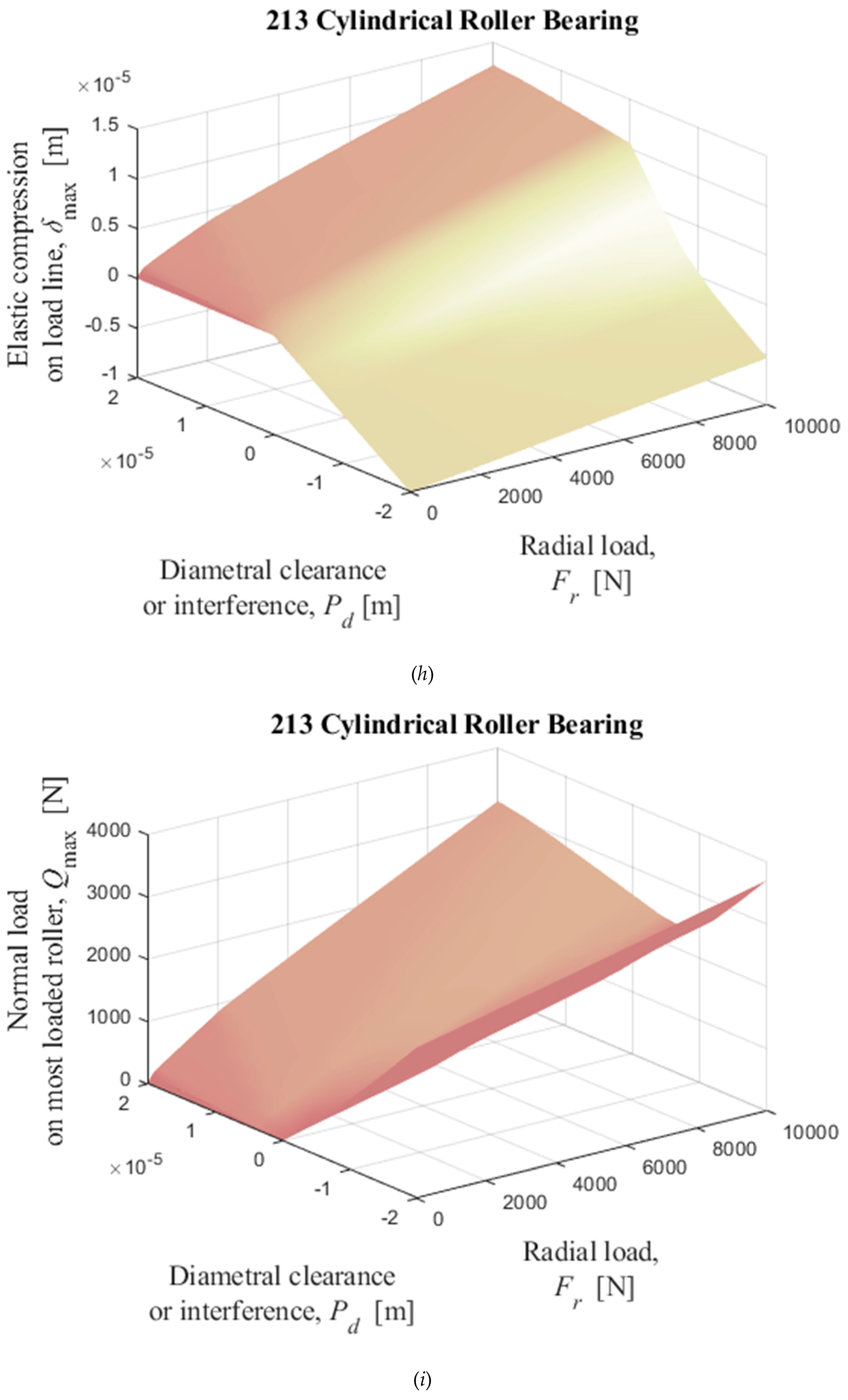
3.3. Numerical results for ball and rollers bearings as diametral clearance and external radial load functions
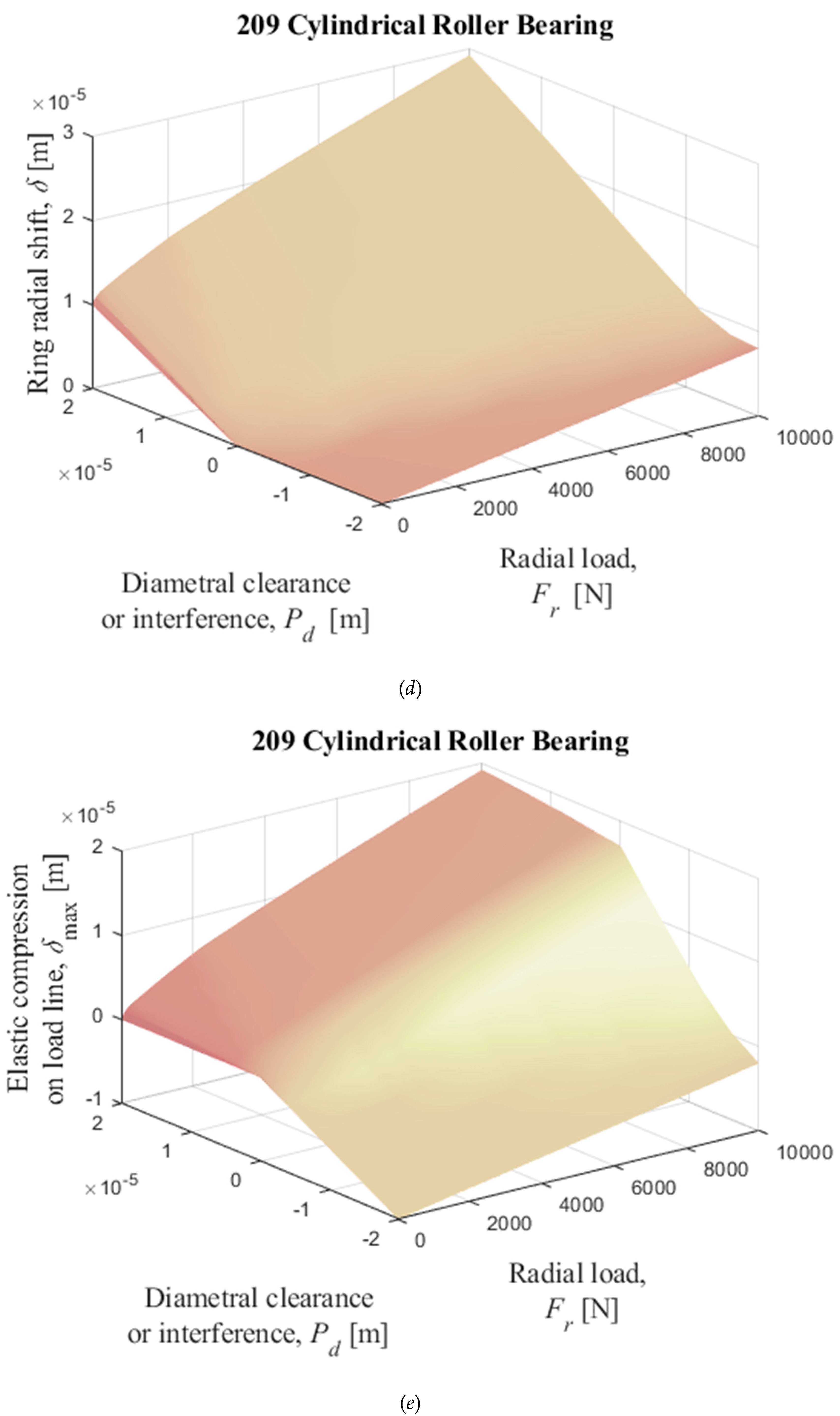
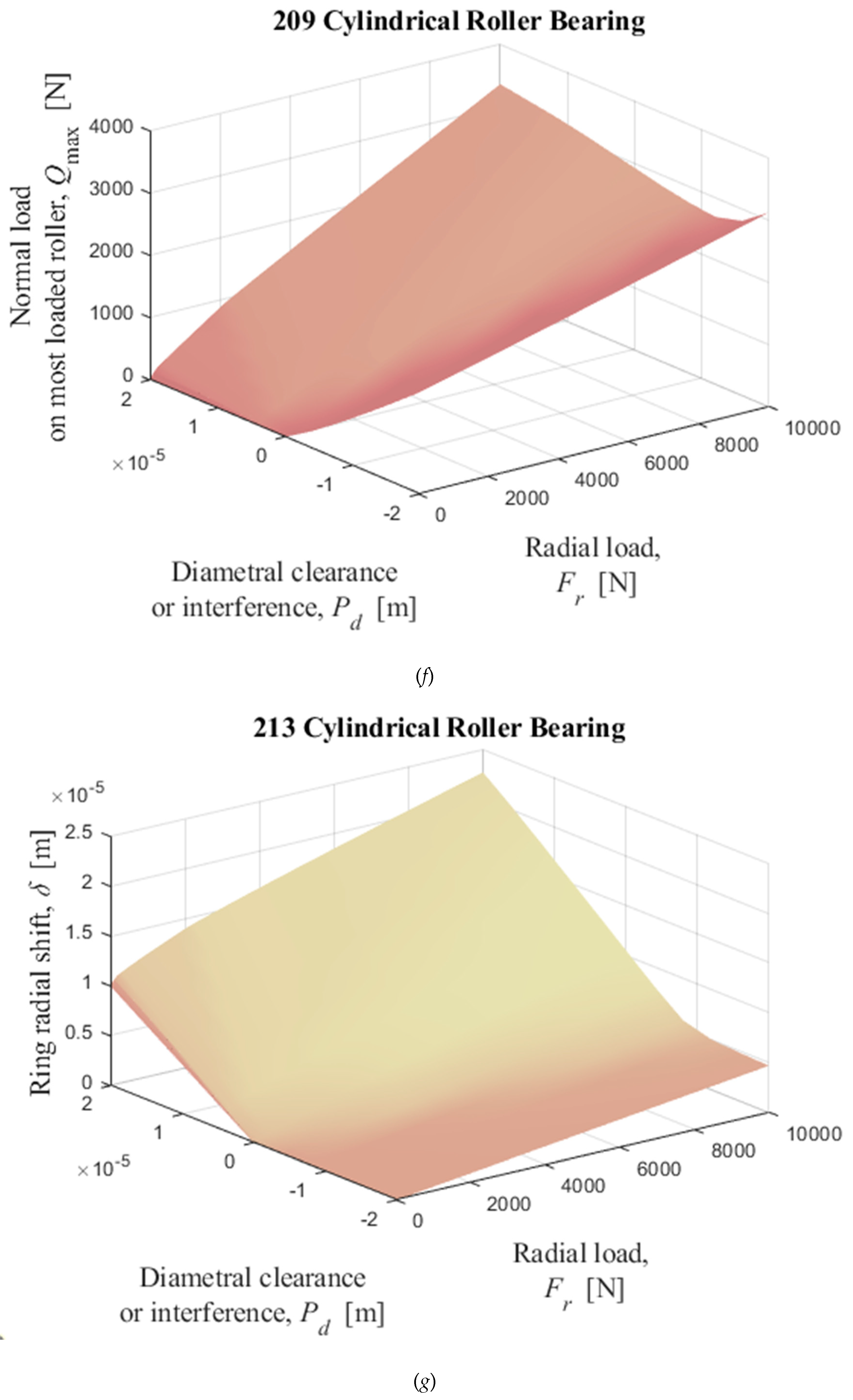
Finally, since the numerical solution of equations (35) and (36) is an effective and accurate way to obtain the load distribution on the rolling elements of a bearing, Figure 15 and Figure 16 show how some variables - relative displacement between rings, maximum deflection and load on the most loaded element - behave as a function of radial load and radial clearance for some ball and roller bearings. The Figure 15 shows the numerical solutions obtained by solving the iterative equations (35) and (36) for 209, 210, and 218 ball bearings, using Table I data as input data; and Figure 16 shows the numerical solutions for 209, 213, and 205 cylindrical roller bearings, using Table II data as input data. Initial δ estimates for each radial load was given as being 10−5 m. The first columns of the Figure 15 and Figure 16 show the radial displacement of the inner ring with respect to the outer ring; the second columns show the elastic compression on the loading line and the third columns show the most loaded rolling element normal load. All figures are functions of diametrical clearance or interference - ranging from −2×10⁻⁵ to 2×10⁻⁵ m - and external radial load - ranging from 0 to 10,000 N.
4. Conclusions
It has been demonstrated that it is possible to easily and accurately obtain the radial distribution of the external load applied to a rolling element bearing by solving the discrete scalar quasi-static equilibrium equation using the Newton-Raphson scheme. Approximate methods using curves fitted to the numerical solution of Sjövall's radial integrals - load zone or load factor functions - are routinely used to obtain the radial external load distribution. In this work it is shown that this distribution can be obtained with greater efficiency and accuracy using the direct method solved by the Newton-Raphson scheme. Besides, the approximate methods described in the literature were compared with the discrete method Newton-Raphson solution and the errors were quantified as a function of the loading. An approximate method was proposed that fits the solutions of the numerical solutions of the Sjövall’s integrals within a range of ±2%, which has shown to have better performance than other approximations for small load zones.
Acknowledgments
The author thanks the collaboration of the following institutions: National Council for Scientific and Technological Development (CNPq); Coordination for the Improvement of Higher Education Personnel (CAPES); Research Support Foundation of the State of São Paulo (FAPESP); Ministry of Science, Technology and Innovation (MCTI); National Institute for Space Research (INPE).
Statements and Declarations
The author declares that no funds, grants, or other support were received during the preparation of this manuscript. The author has no relevant financial or non-financial interests to disclose. There is no conflict of interests. The datasets generated and/or analyzed during the current study are contained in this manuscript and are available from the corresponding author upon request.
References
- Stribeck, R. Ball Bearings for Various Loads. Trans. ASME 1907, 29, 420–463. [Google Scholar]
- Sjövall, H. The Load Distribution within Ball and Roller Bearings under Given External Radial and Axial Load. Teknisk Tidskrift, Mek (1933), h.9.
- Palmgren, A. Ball and Roller Bearing Engineering. 3rd ed., Burbank, Philadelphia, (1959).
- Ricci, M.C. On the Stribeck’s numbers in radially loaded rolling element bearings. Proceedings CREEM2022 (2022). https://abcm.org.br/proceedings/view/CRE2022/0038, accessed in: 08/21/2023.
- Jones, A.B. A general theory for elastically constrained ball and roller bearings under arbitrary load and speed conditions, ASME Journal of Basic Engineering (1960) 309–320. [CrossRef]
- Hertz, H. “On the contact of Rigid Elastic Solids and on Hardness,” in Miscellaneous Papers, MacMillan, London. 163-183, 1896.
- Harris, T.A. Rolling Bearing Analysis. 4th ed., John Willey & Sons Inc., New York, (2001).
- Rumbarger, J. Thrust Bearings with Eccentric Loads," Mach. Des., Feb. 15, 1962.
- Ricci, M.C. Internal loading distribution in statically loaded ball bearings subjected to an eccentric thrust load, Mathematical Problems in Engineering. Mathematical Problems in Engineering 2009, 2009, 471804. [Google Scholar] [CrossRef]
- Houpert, L. A Uniform Analytical Approach for Ball and Roller Bearing, Proc. at the STLE/ASME Tribology Conf., San Francisco. ASME J. Tribol., 1997, 119, 851–857. [Google Scholar] [CrossRef]
- Jones, A.B. Analysis of Stresses and Deflections, New Departure Engineering Data, Bristol, Conn., 1946.
- Tomović, R. Calculation of the necessary level of external radial load for inner ring support on q rolling elements in a radial bearing with internal radial clearance. International Journal of Mechanical Science 2012, 60, 23–33. [Google Scholar] [CrossRef]
- Tomović, R.; Miltenović, V.; Banić, M.; Miltenović, A. Vibration response of rigid rotor in unloaded rolling element bearing. International Journal of Mechanical Sciences 2010, 52, 1176–1185. [Google Scholar] [CrossRef]
- Oswald, F.B.; Zaretsky, E.V.; Poplawski, J.V. Effect of Internal Clearance on Load Distribution and Life of Radially Loaded Ball and Roller Bearings. Tribology Transactions 2012, 55, 245–265. [Google Scholar] [CrossRef]
- Xiaoli, R.; Jia, Z.; Ge, R. Calculation of radial load distribution on ball and roller bearings with positive, negative and zero clearance, International Journal of Mechanical Sciences 2017. [CrossRef]
- Sinha, R.; Sahoo, V. Effect of relative movement between bearing races on load distribution on ball bearings. SN Appl. Sci, 2020; 2, 2100. [Google Scholar] [CrossRef]
- Zhang, J.; Fang, B.; Hong, J.; Zhu, Y. Effect of preload on ball-raceway contact state and fatigue life of angular contact ball bearing, Tribology International. [CrossRef]
- Hou, Y.; Yin, Y.; Wang, X. Correction of Radial Load Distribution Integral for Radial Bearings. https://www.researchsquare.com/article/rs-36826/v1, acessed on 03/29/2022.
- Harris, T.A.; Kotzalas, M.N. Rolling Bearing Analysis: Essential Concepts of Bearing Technology, 5th Edition, CRC Press, Boca Raton, FL, 2007.
- Nagatomo, T.; Takahashi, K.; Okamura, Y.; Kigawa, T.; Noguchi, S. Effects of Load Distribution on Life of Radial Roller Bearings. Journal of Tribology, 2012, 134, 021101. [Google Scholar] [CrossRef]
- Han., Y.; Yang, L.; Xu, T. Analysis of static stiffness fluctuation in radially loaded ball and roller bearings. Arch Appl Mech 2021, 91, 1757–1772. [Google Scholar] [CrossRef]
- Liu, J.; Shao, Y. An improved analytical model for a lubricated roller bearing including a localized defect with different edge shapes. J Vib Control 2017, 24, 3894–3907. [Google Scholar] [CrossRef]
- Liu, J.; Shao, Y. Dynamic modeling for rigid rotor bearing systems with a localized defect considering additional deflections at the sharp edges. J Sound Vib, 2017; 398, 84–102. [Google Scholar] [CrossRef]
- Sinha, R.; Sahoo, V.; Paswan, M. 2021. Radial load distribution by balls in a ball bearing with variable clearance, Mechanics Based Design of Structures and Machines. [CrossRef]
- Hamrock, B.J.; Anderson, W.J. Rolling-Element Bearings. NASA RP 1105, (1983).
- Ricci, M. Comparing three calculation methods of load distribution in radial bearings, in: eccomas2022. URL https://www.scipedia.com/public/Ricci_2022a, acessed in: 08/21/2023.
- Eschmann, P.; Hasbargen, L.; Weigand, K. Ball and Roller Bearings, Theory, Design and Application, 2nd Edition, R. Oldenbourg Verlag, (1978).
- Harris, T.A. Rolling Bearing Analysis, Third Edition, Wiley-Interscience, Wiley & Sons, (1991).
- Patra, P.; Saran, V.H.; Harsha, S.P. Vibration response analysis of high-speed cylindrical roller bearings using response surface method, Proc IMechE Part K: J Multi-body Dynamics 0(0), 1-14, (2020). [CrossRef]
- Chudzik, A.; Warda, B. “Effect of radial internal clearance on the fatigue life of the radial cylindrical roller bearing,”. Eksploatacja i Niezawodnosc – Maintenance and reliability, 2019; 21, 211–219. [Google Scholar] [CrossRef]
- ESDU, “Contact Stresses,” Engineering Science Data Unit, Item 78035, Institution of Mechanical Engineers, London, England, (1978).
- Ricci, M.C. On load distribution factors in radially loaded rolling element bearings, to be published.
Figure 1.
Rolling elements angular positions in the radial plane, which is perpendicular to the bearing’s axis of rotation, Δψ = 2π/Z, ψj = Δψ(j − 1), j = 1, …, Z; Pd represents the diametrical clearance; do, di, D represent outer, inner raceways, and rolling element diameters, respectively.
Figure 1.
Rolling elements angular positions in the radial plane, which is perpendicular to the bearing’s axis of rotation, Δψ = 2π/Z, ψj = Δψ(j − 1), j = 1, …, Z; Pd represents the diametrical clearance; do, di, D represent outer, inner raceways, and rolling element diameters, respectively.
Figure 2.
Radially loaded bearing with diametrical clearance Pd > 0, at which the load line passes through the most loaded rolling element’s center: (a) Concentric arrangement; (b) Initial contact; (c) Interference. Source: Hamrock and Anderson [25].
Figure 2.
Radially loaded bearing with diametrical clearance Pd > 0, at which the load line passes through the most loaded rolling element’s center: (a) Concentric arrangement; (b) Initial contact; (c) Interference. Source: Hamrock and Anderson [25].
Figure 3.
Numerical integration of Eq. (13), approximations and relative errors with respect to the numerical integration, as functions of ε, for 0 ≤ ε ≤ 2. (a) n = 10/9; HA’s approx. for n = 1 (Eq. (16)); OZP’s approx. (Eqs. (17)-(19)); Ricci’s approx. (Eqs. (20)-(22)). (b) n = 3/2; HA’s approx. (Eq. (23)) multiplied by the factor (2ε)-3/2; OZP’s approx. (Eqs. (24)-(26)); Ricci’s approx. (Eqs. (27)-(29)). HA-Hamrock and Anderson; OZP-Oswald, Zaretsky and Poplawski.
Figure 4.
Numerical integration of Eq. (10), approximations and relative errors with respect to the numerical integration, as functions of ψl, for 0 ≤ ψl ≤ 180o. (a) n = 10/9; HA’s approx. for n = 1 (Eq. (15)); OZP’s approx. (Eqs. (17)-(19)); Ricci’s approx. (Eqs. (20)-(22)), with last two approximations multiplied by the factor between curved brackets raised to the power n = 10/9 in the Eq. (14); (b) n = 3/2; HA’s approx. (Eq. (23)); OZP’s approx. (Eqs. (24)-(26)); Ricci’s approx. (Eqs. (27)-(29)), with last two approximations multiplied by the factor between curved brackets raised to the power n = 3/2 in the Eq. (14).
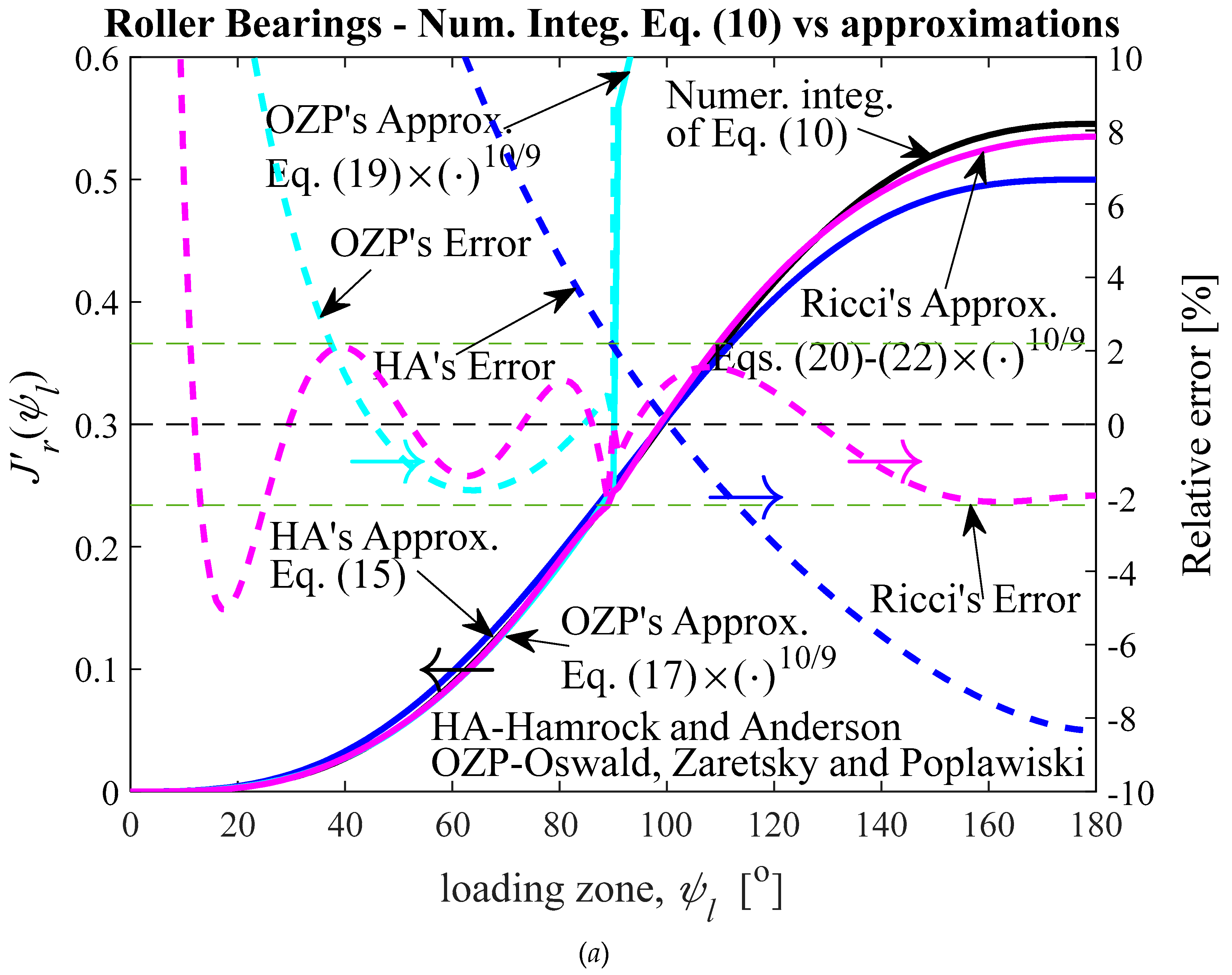
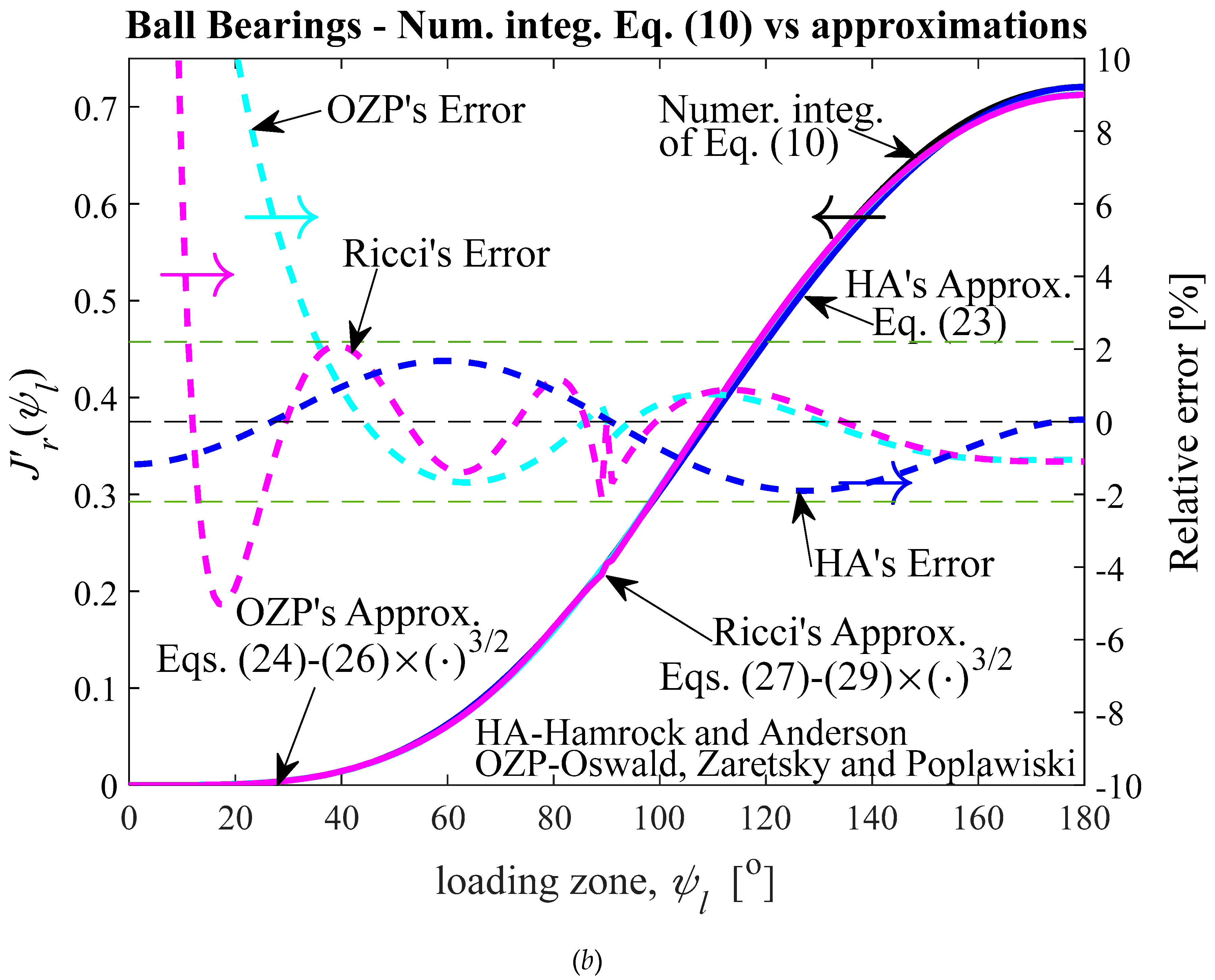
Figure 5.
Displacements between rigid rings of deep-groove or angular-contact ball bearings for six different methods, and relative errors, as a function of external radial load. Results presented in the literature also are shown: (a) and (b) 209, 0 < ε < 0.44, 0° < ψl < 83.37°; (c) and (d) 210, 0 < ε < 0.44, 0° < ψl < 83.16°; (e) and (f) 218, 0 < ε < 0.09, 0°< ψl < 34.74°. HA-Hamrock and Anderson; OZP-Oswald, Zaretsky and Poplawski.
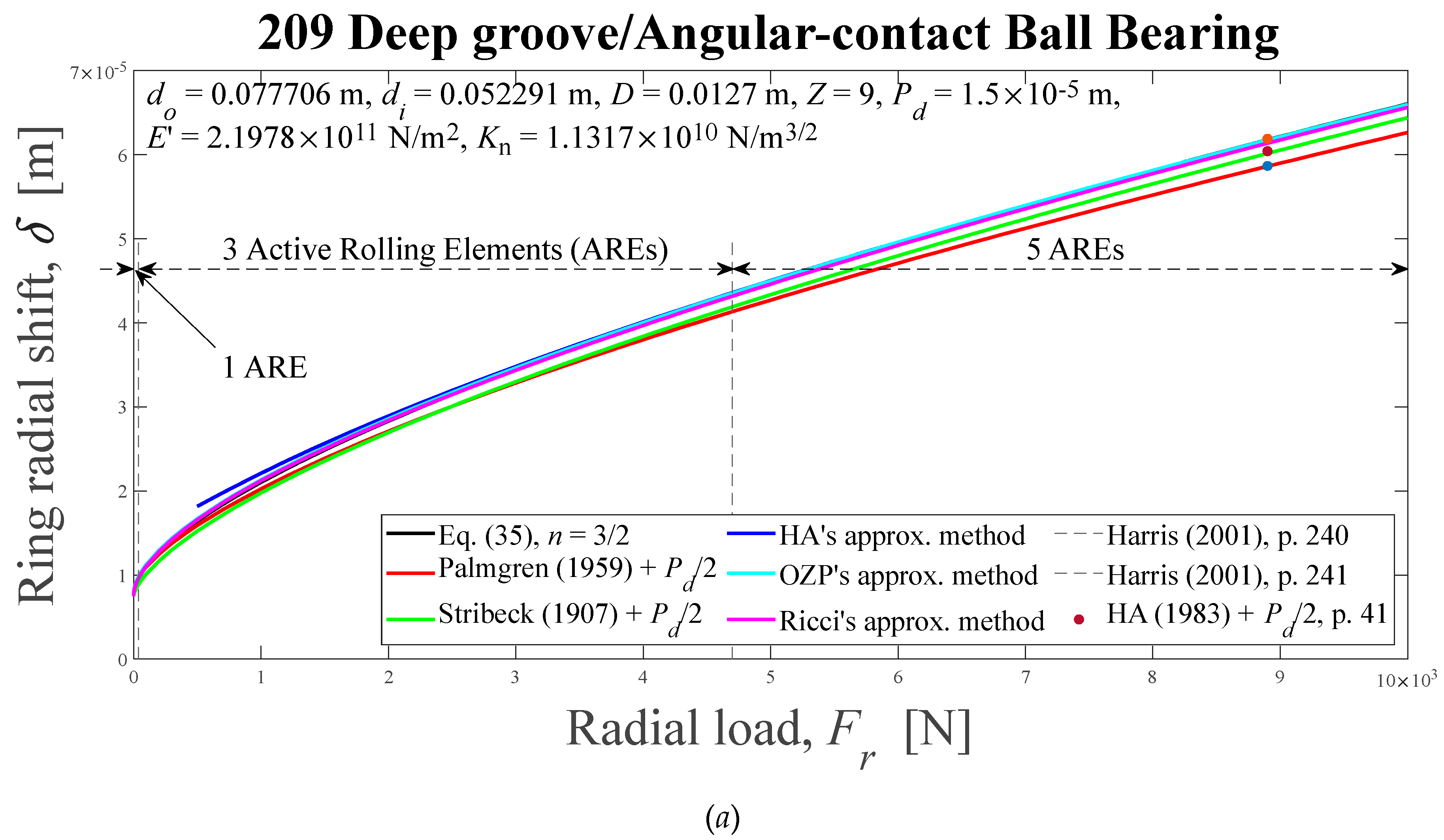
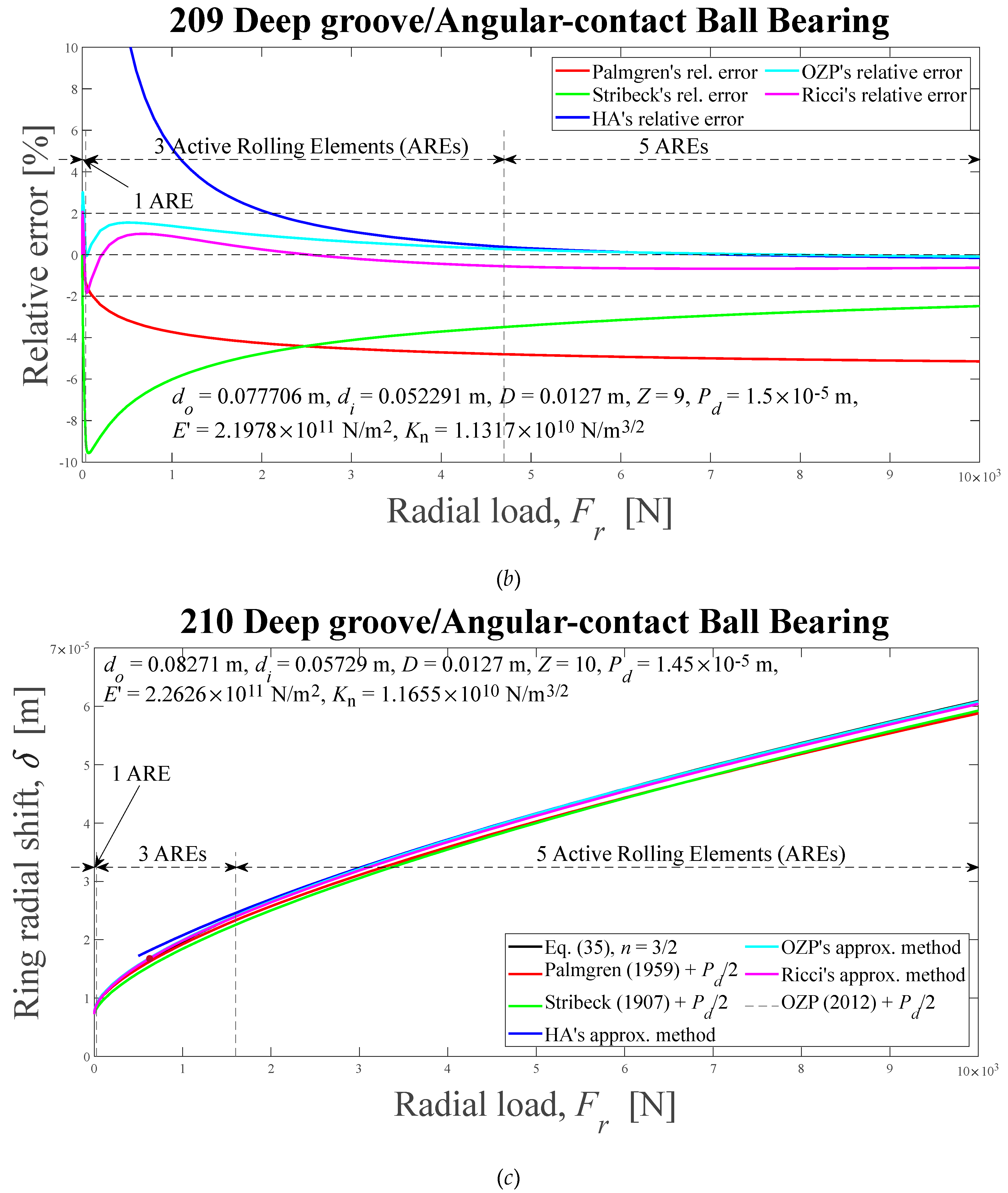
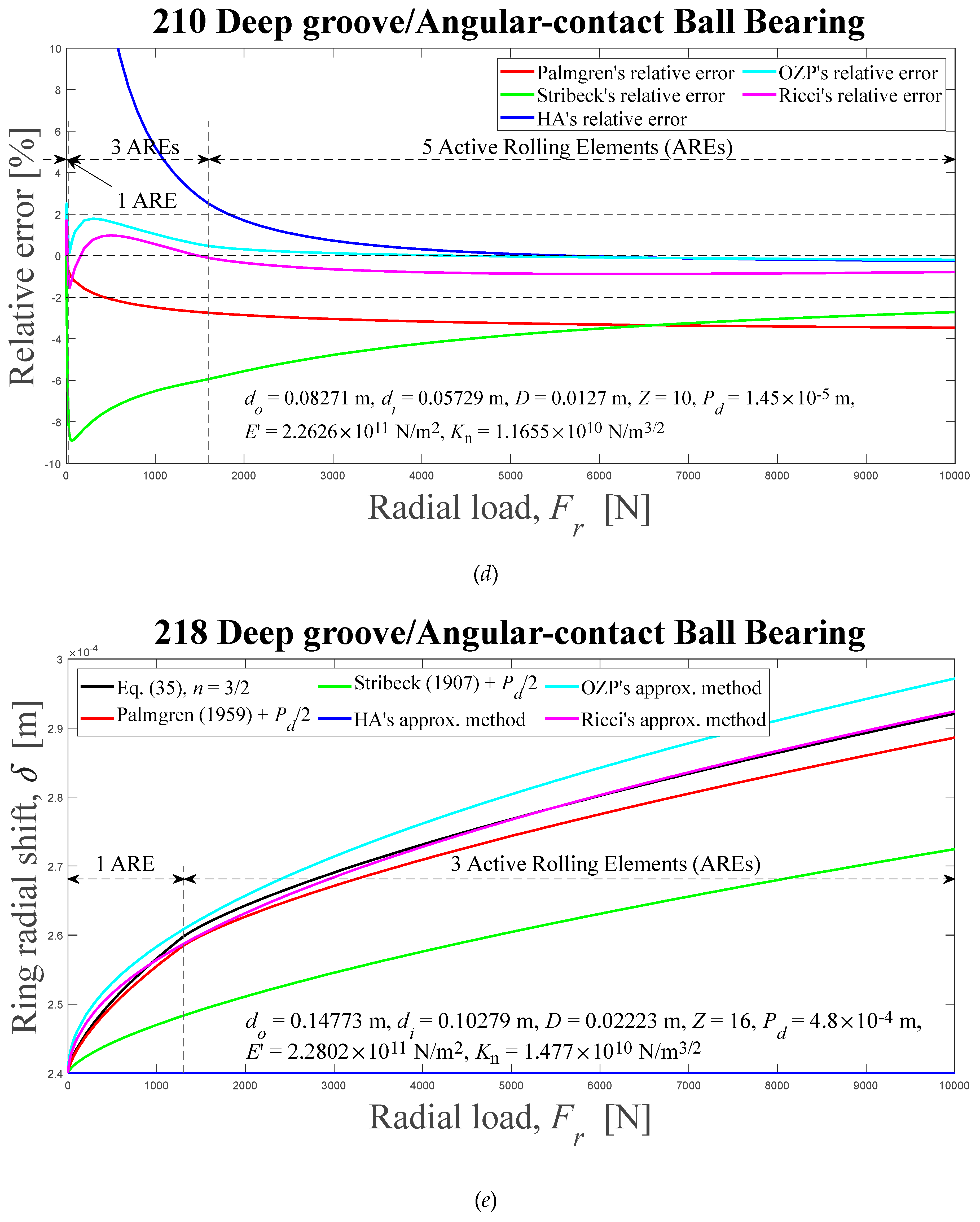
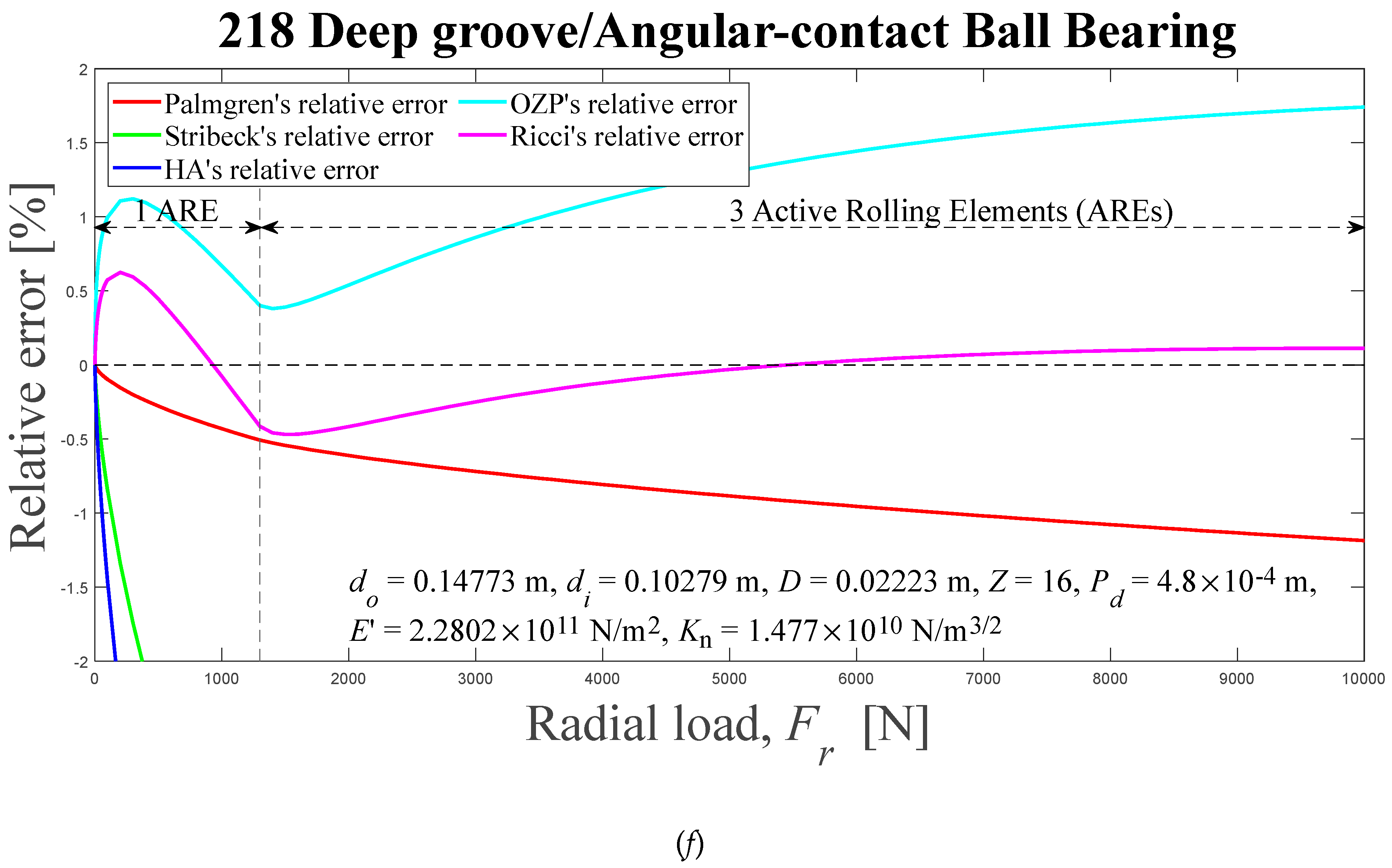
Figure 6.
Load zones, ψl, and load distribution factors, ε, computed using the Eq. (35) solved by Newton-Raphson's scheme, as radial external load functions. (a) 209, (b) 210, and (c) 218.
Figure 6.
Load zones, ψl, and load distribution factors, ε, computed using the Eq. (35) solved by Newton-Raphson's scheme, as radial external load functions. (a) 209, (b) 210, and (c) 218.
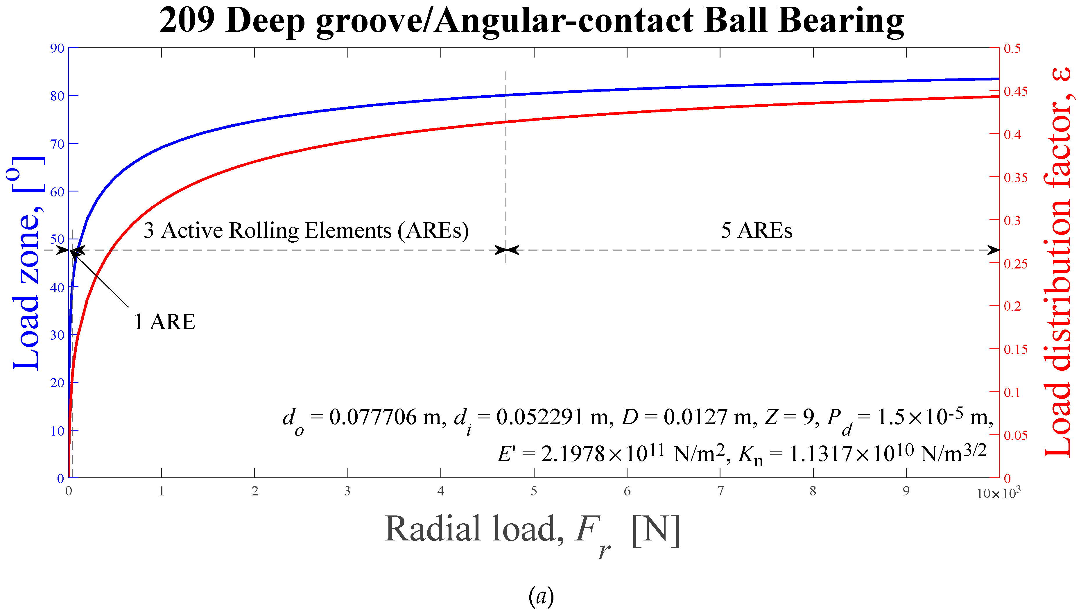
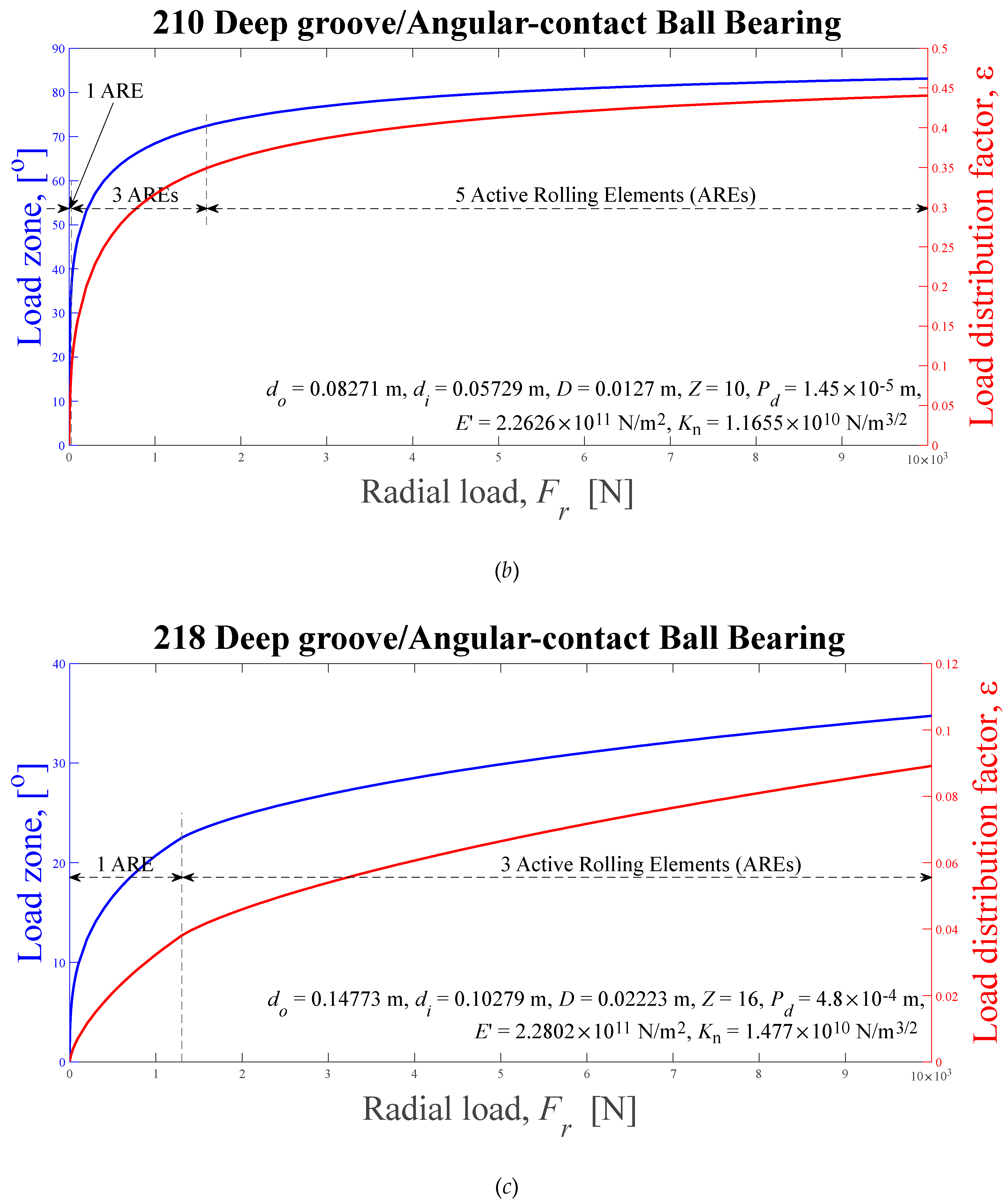
Figure 7.
Absolute relative Error differences between the Ricci approximation and Palmgren’s, Stribeck’s, HA’s, and OZP’s, approximations, as external radial load functions, for ball bearings: (a) 209, (b) 210, (c) 218. HA-Hamrock and Anderson; OZP-Oswald, Zaretsky and Poplawski.
Figure 7.
Absolute relative Error differences between the Ricci approximation and Palmgren’s, Stribeck’s, HA’s, and OZP’s, approximations, as external radial load functions, for ball bearings: (a) 209, (b) 210, (c) 218. HA-Hamrock and Anderson; OZP-Oswald, Zaretsky and Poplawski.
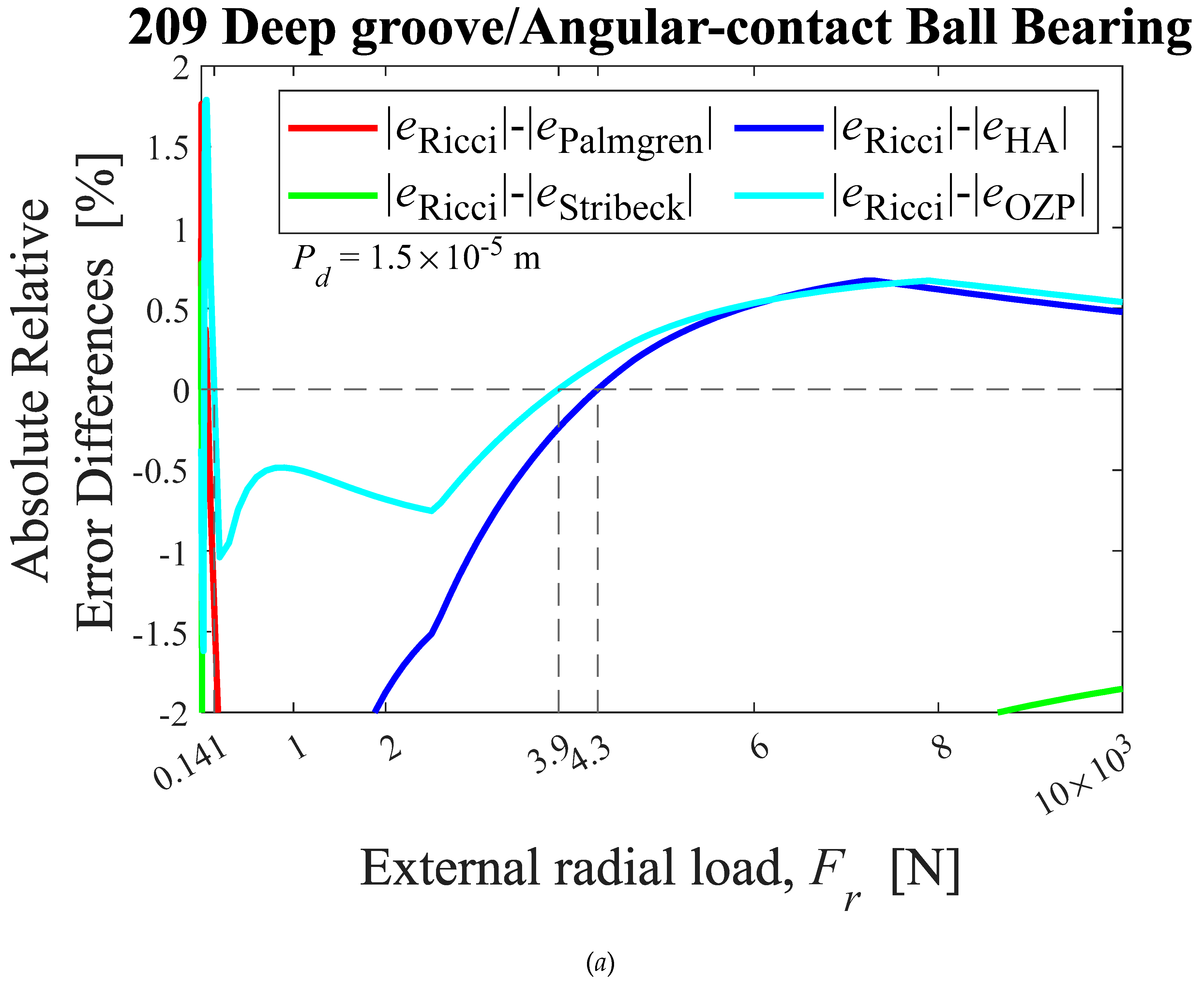
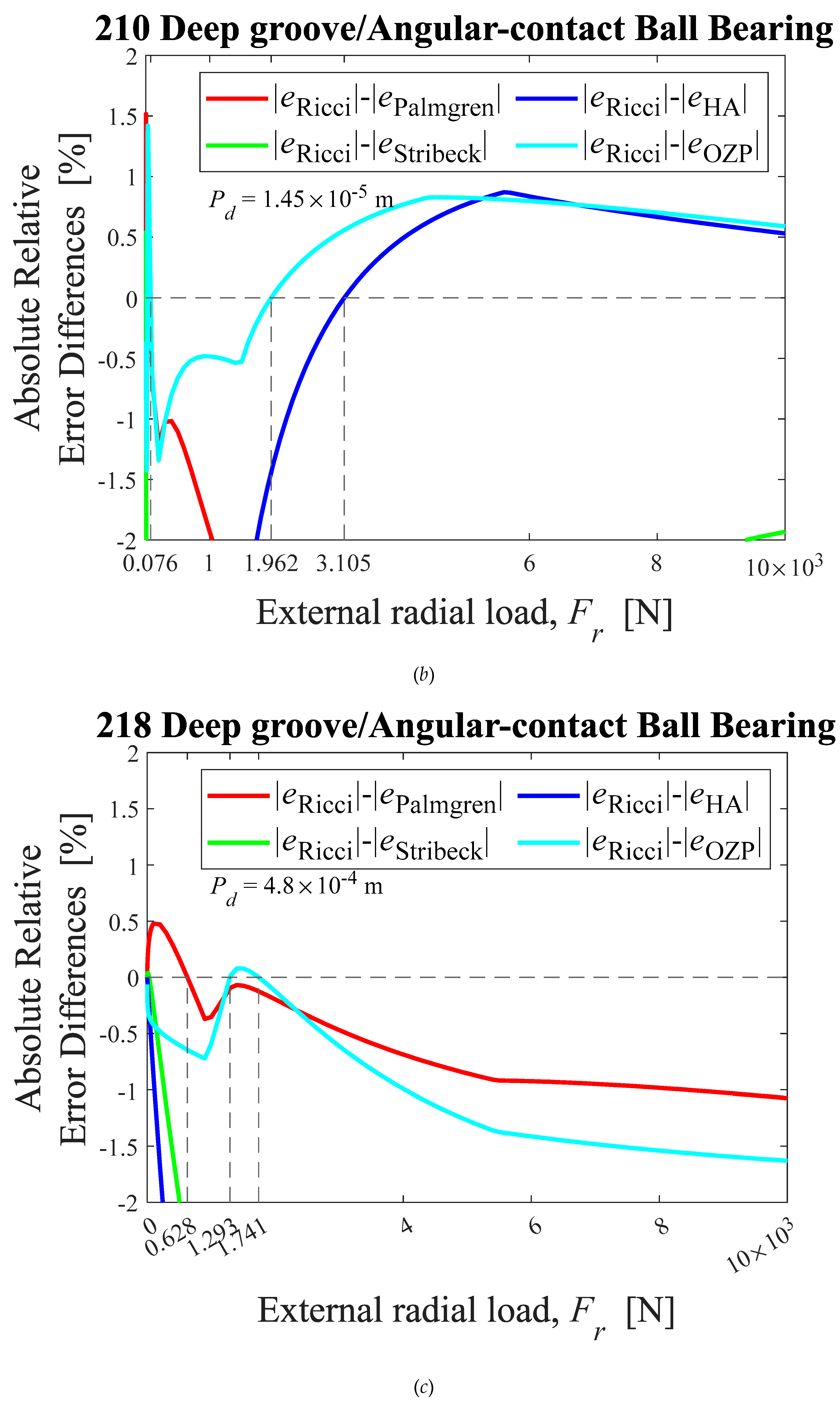
Figure 8.
Displacements between rigid rings, computed using the Eq. (35), for a cylindrical roller bearing used in Ref. [25], as external radial load functions, applied to the inner ring, for some effective load-deflection factor values.
Figure 8.
Displacements between rigid rings, computed using the Eq. (35), for a cylindrical roller bearing used in Ref. [25], as external radial load functions, applied to the inner ring, for some effective load-deflection factor values.

Figure 9.
Outer and inner contact semi-widths, computed using the Eq. (35), for the cylindrical roller bearing used in Ref. [25], as external radial load functions, for effective load-deflection factor values K1 given by the dashed lines in Figure 10.
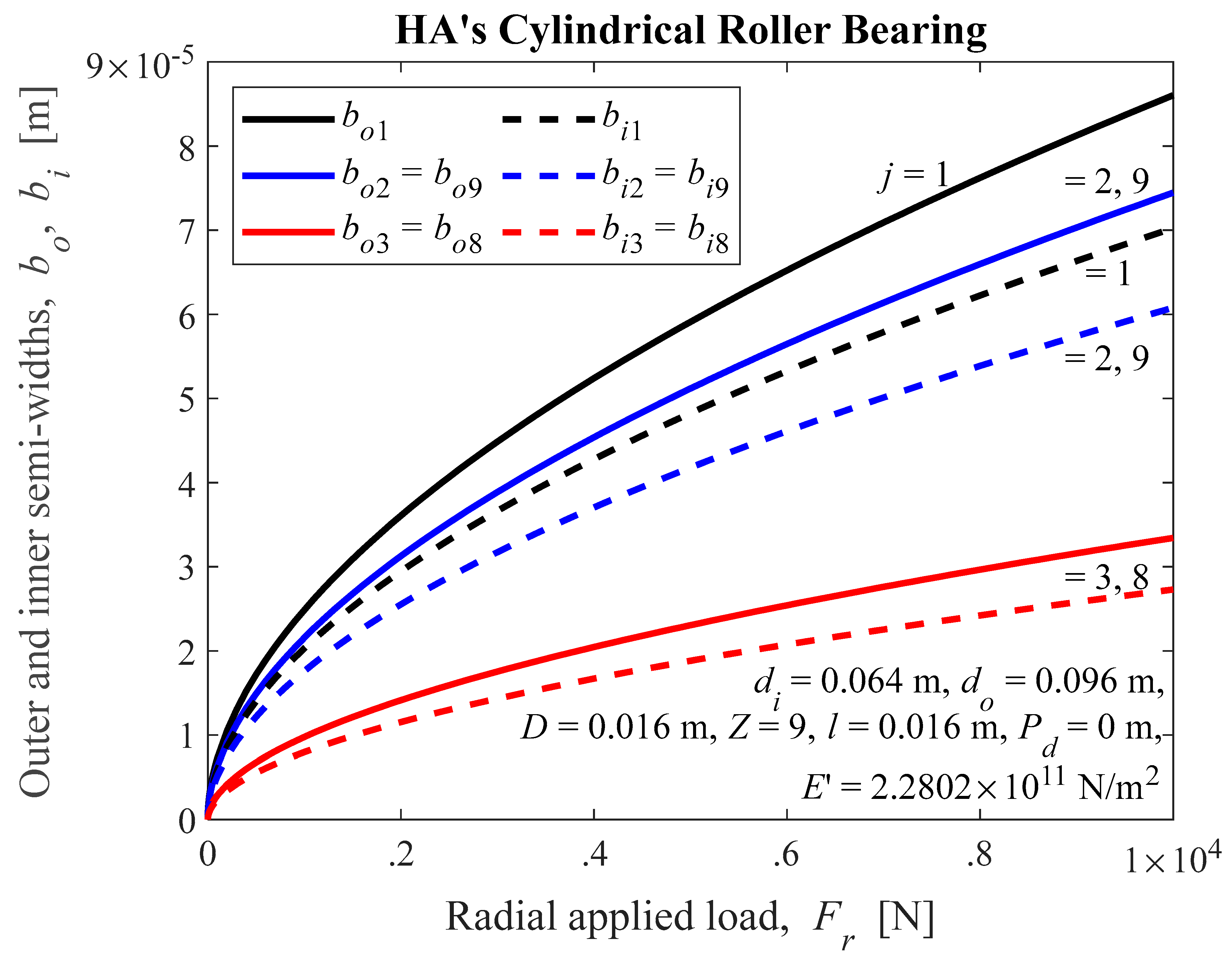
Figure 10.
Outer, inner and effective load-deflection ESDU factors, computed using the Eq. (35), for the cylindrical roller bearing used in Ref. [25], as external radial load functions.
Figure 10.
Outer, inner and effective load-deflection ESDU factors, computed using the Eq. (35), for the cylindrical roller bearing used in Ref. [25], as external radial load functions.

Figure 11.
Convergence’s procedure relative error in percentage, in determining the displacement between rings, computed using the Eq. (36), for the cylindrical roller bearing used in Ref. [25], as function of the iterations number.
Figure 11.
Convergence’s procedure relative error in percentage, in determining the displacement between rings, computed using the Eq. (36), for the cylindrical roller bearing used in Ref. [25], as function of the iterations number.
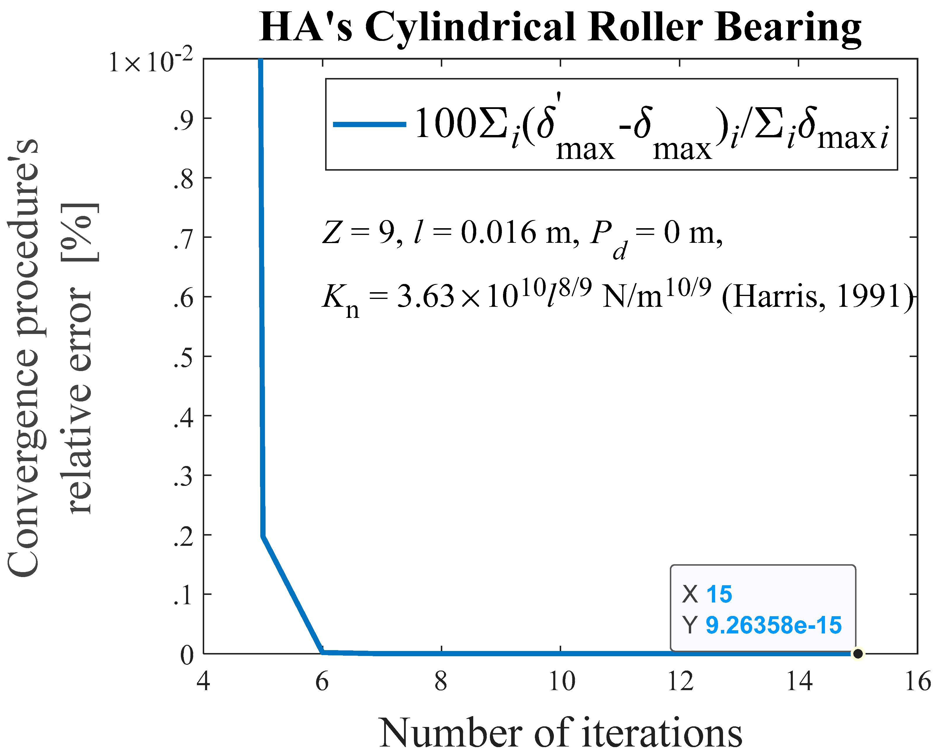
Figure 12.
Displacements between rigid rings and relative errors of the approximations with respect to the numerical solution for cylindrical roller bearings, as external radial load functions, for six different methods: (a) and (b) HA’s, ε = 0.5, ψl = 90°; (c) and (d) 205, 0 < ε < 0.27, 0° < ψl < 62.56°; (e) and (f) 209, 0 < ε < 0.25, 0°< ψl < 60.44°; (g) and (h) 213, ε = 0.5, ψl = 90°. HA-Hamrock and Anderson; OZP-Oswald, Zaretsky and Poplawski.
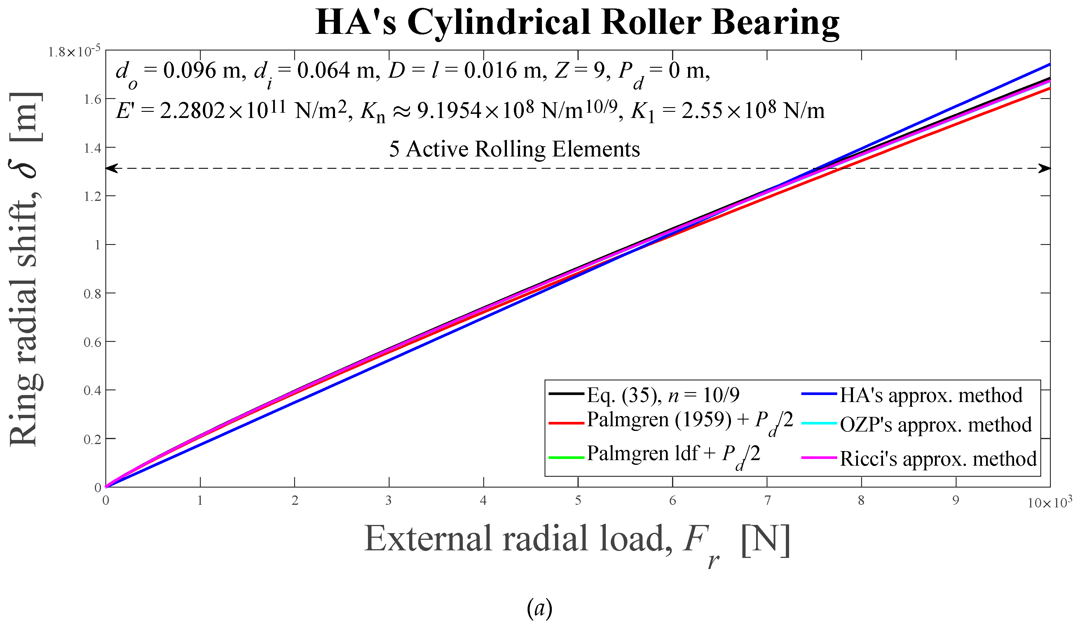
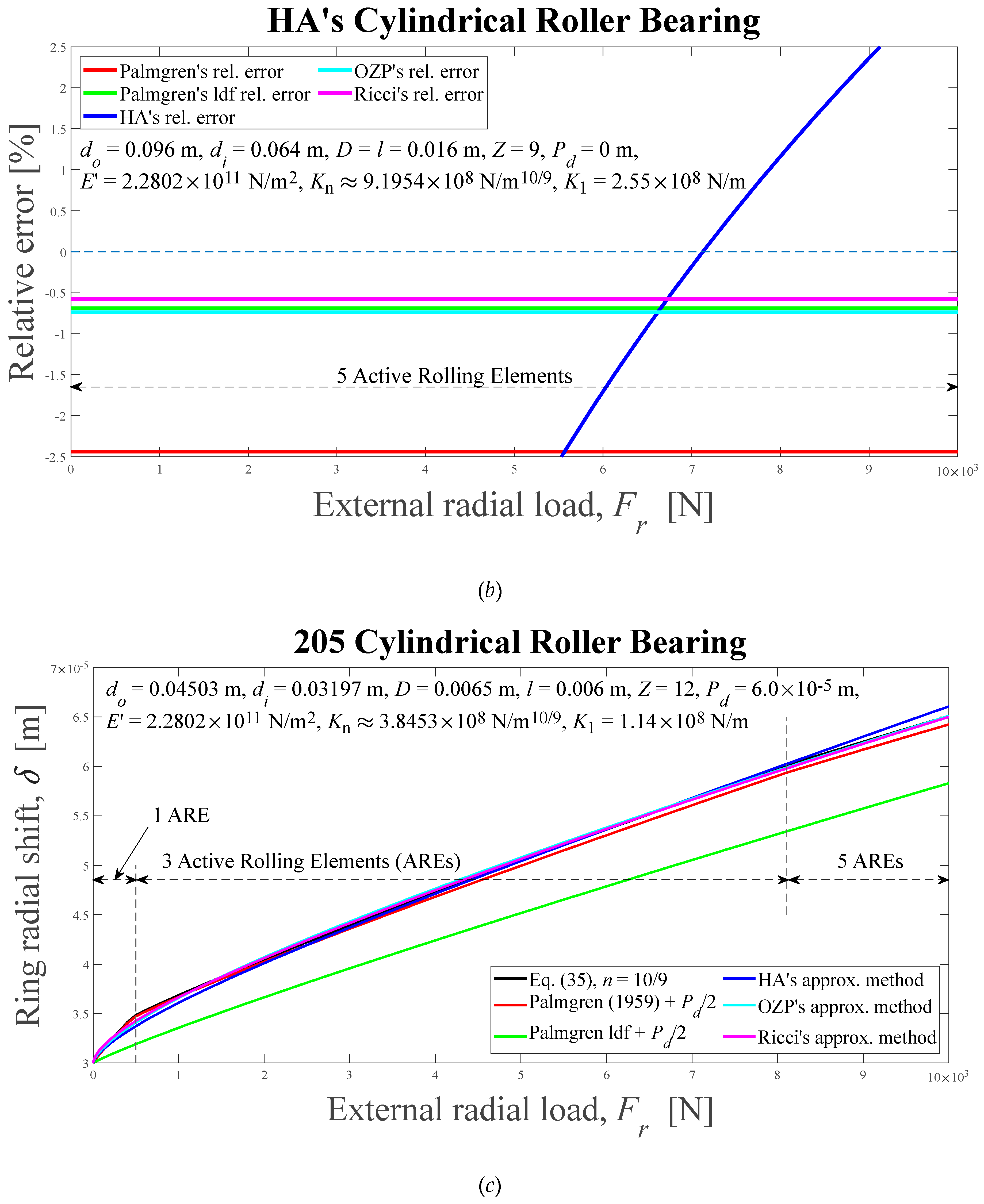
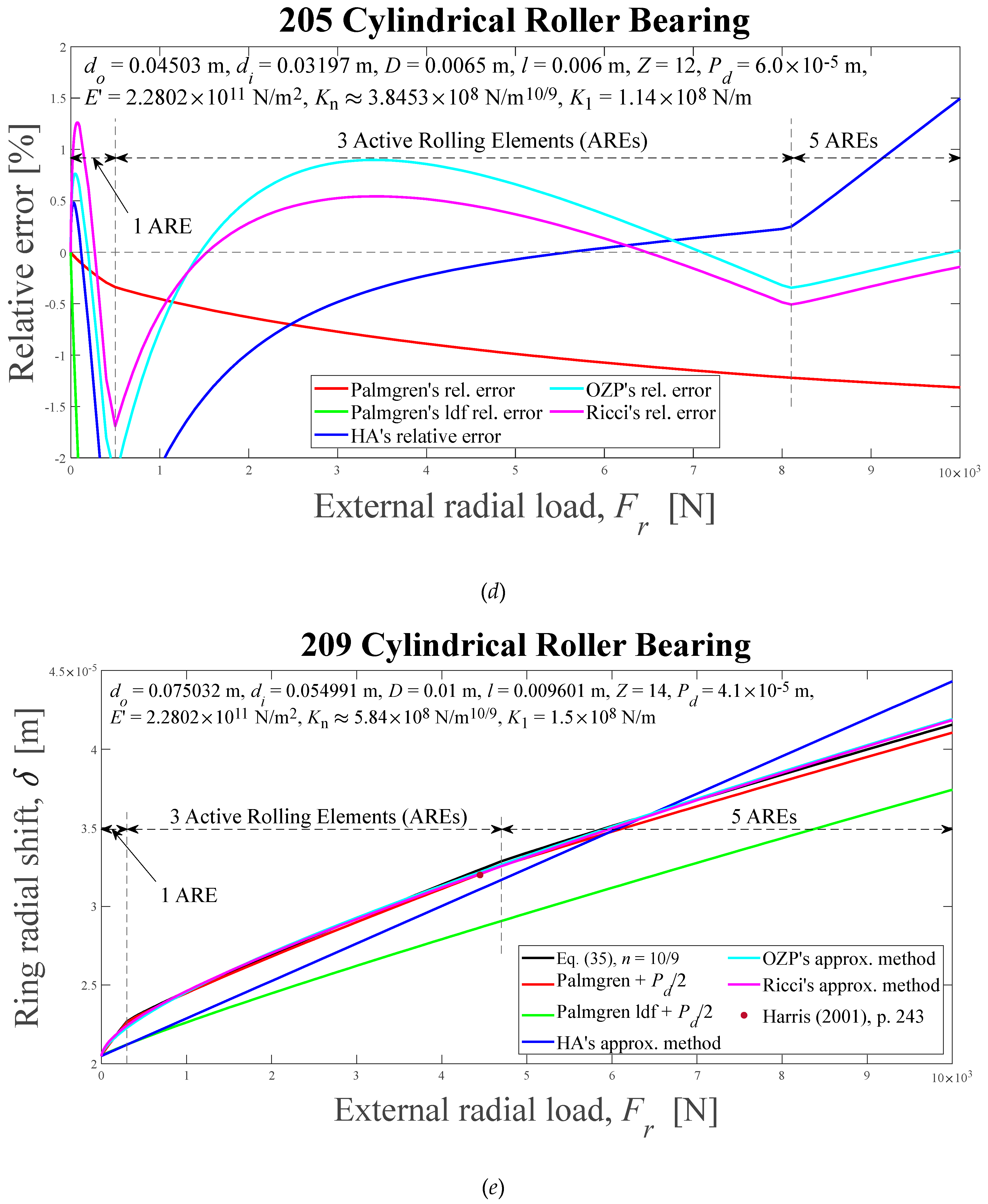
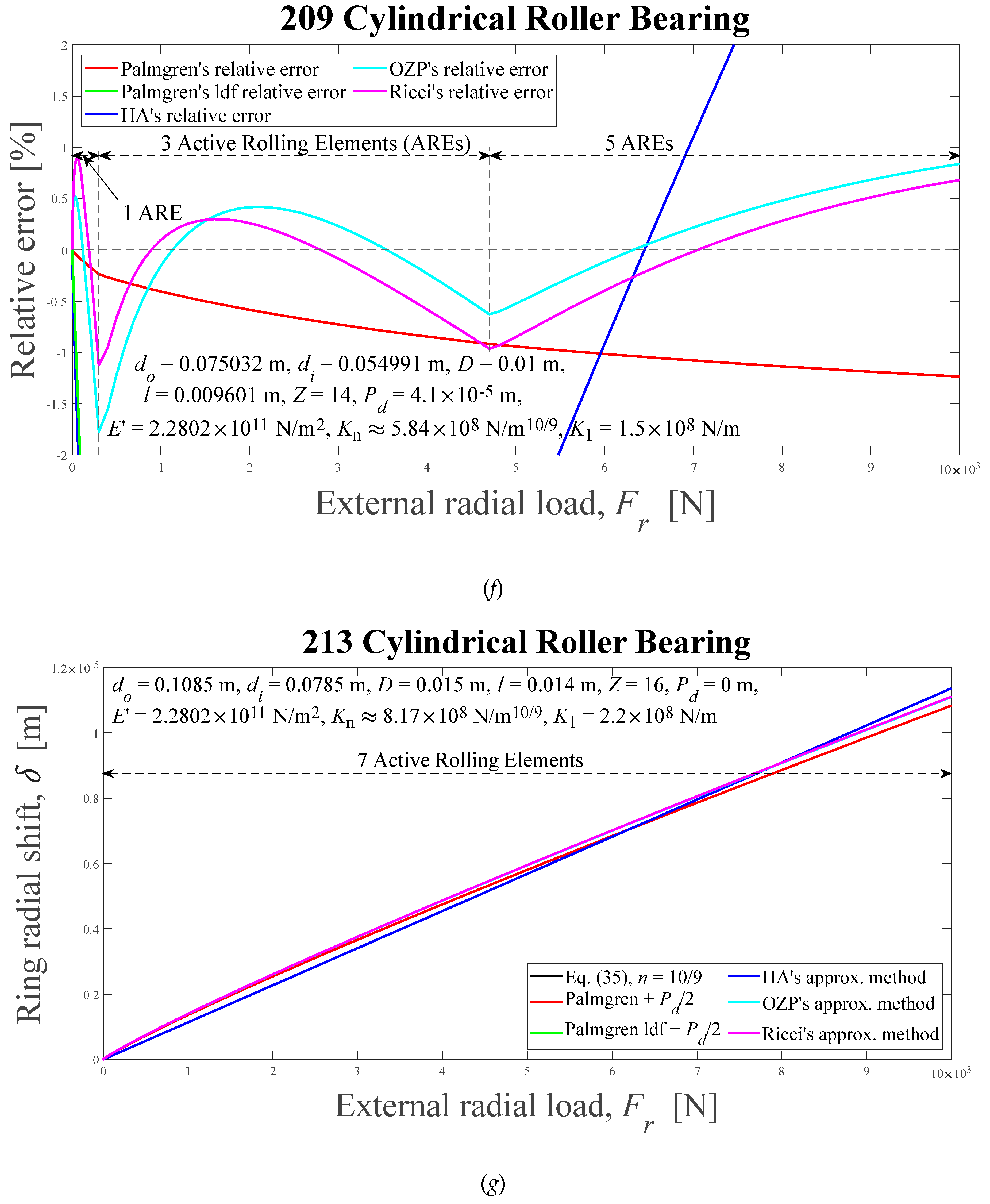
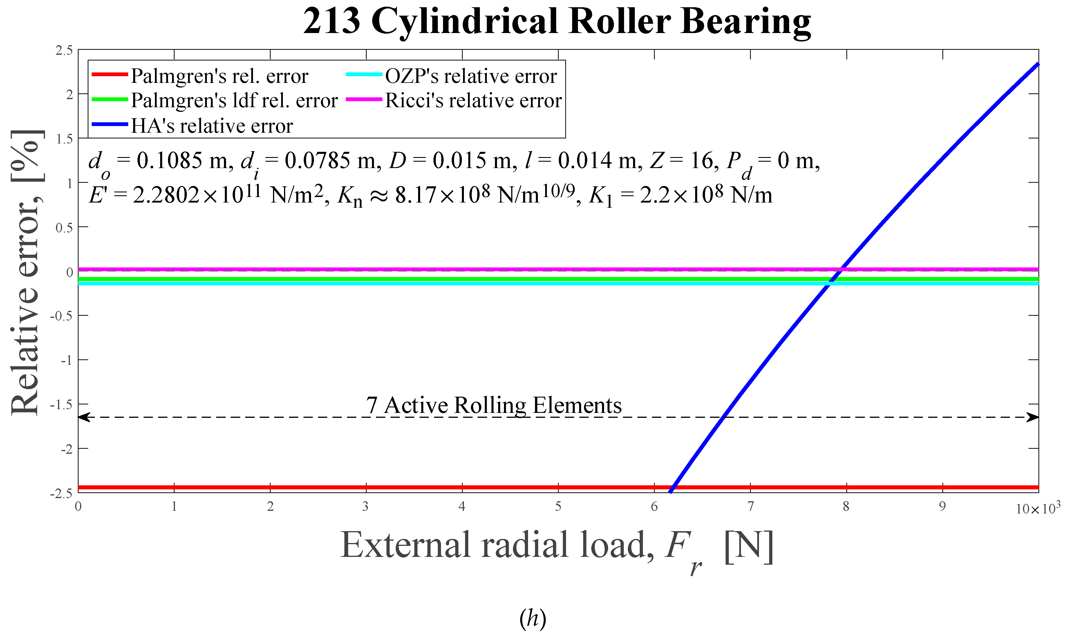
Figure 13.
Load zones, ψl, and load distribution factors, ε, computed using the Eq. (35) solved by Newton-Raphson's scheme, as radial external load functions. (a) HA’s, (b) 205, (c) 209, (d) 213.
Figure 13.
Load zones, ψl, and load distribution factors, ε, computed using the Eq. (35) solved by Newton-Raphson's scheme, as radial external load functions. (a) HA’s, (b) 205, (c) 209, (d) 213.
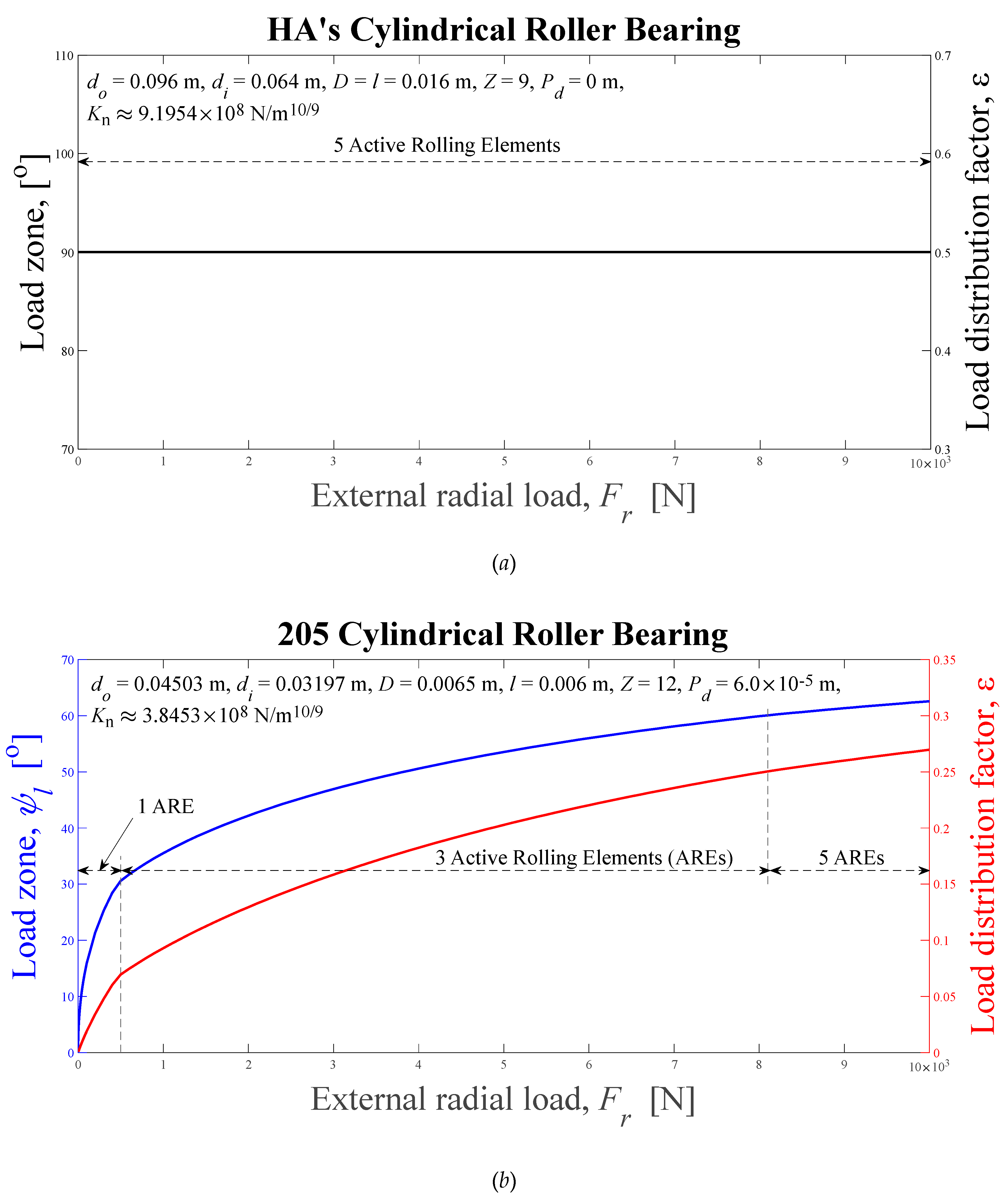
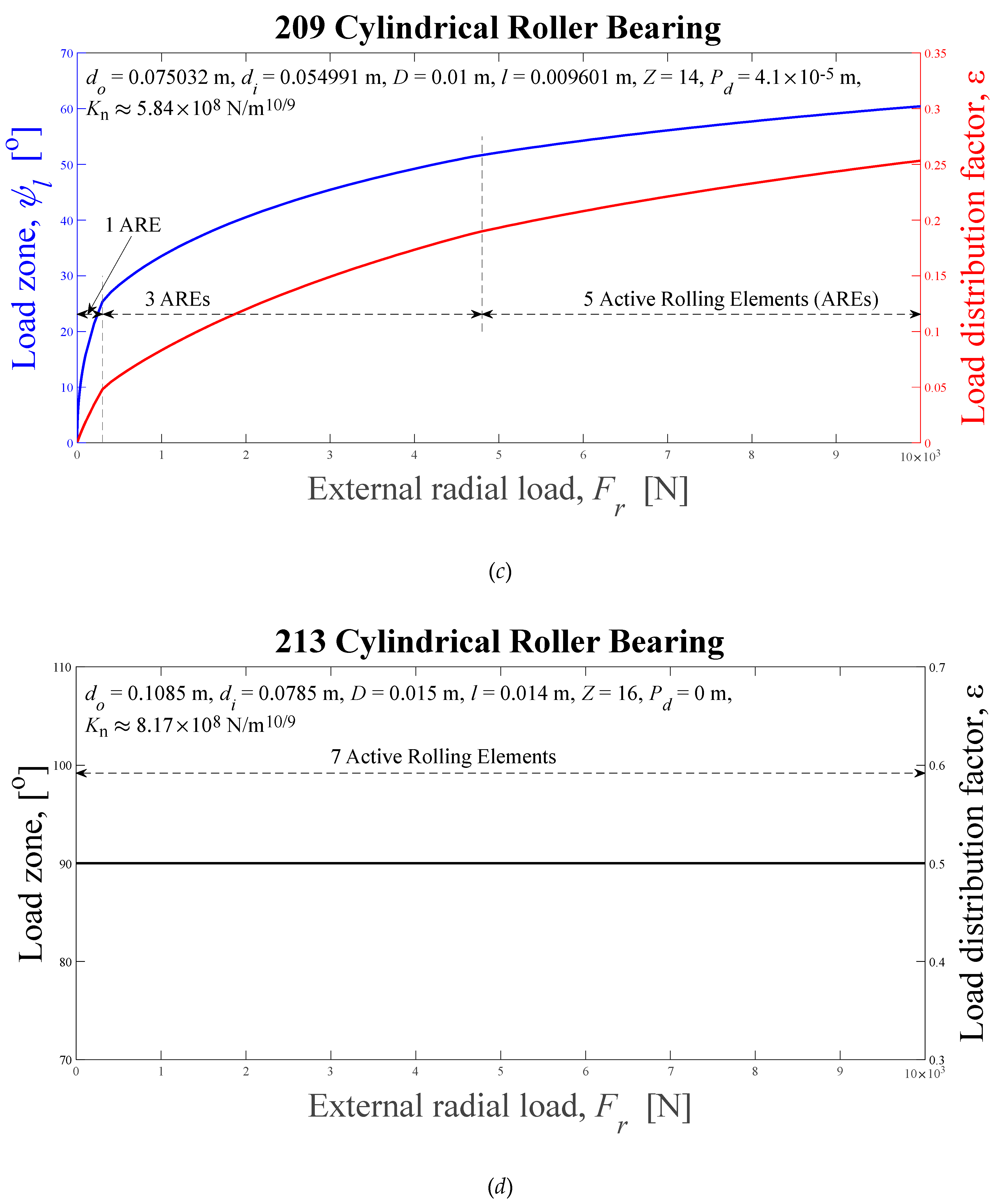
Figure 14.
Absolute relative error differences between the Ricci’s approximation and OZP’s, HA’s, Palmgren’s and Palmgren’s ldf approximations, as external radial load functions, for cylindrical roller bearings: (a) HA’s, (b) 205, (c) 209, (d) 213. HA-Hamrock and Anderson; OZP-Oswald, Zaretsky and Poplawski.
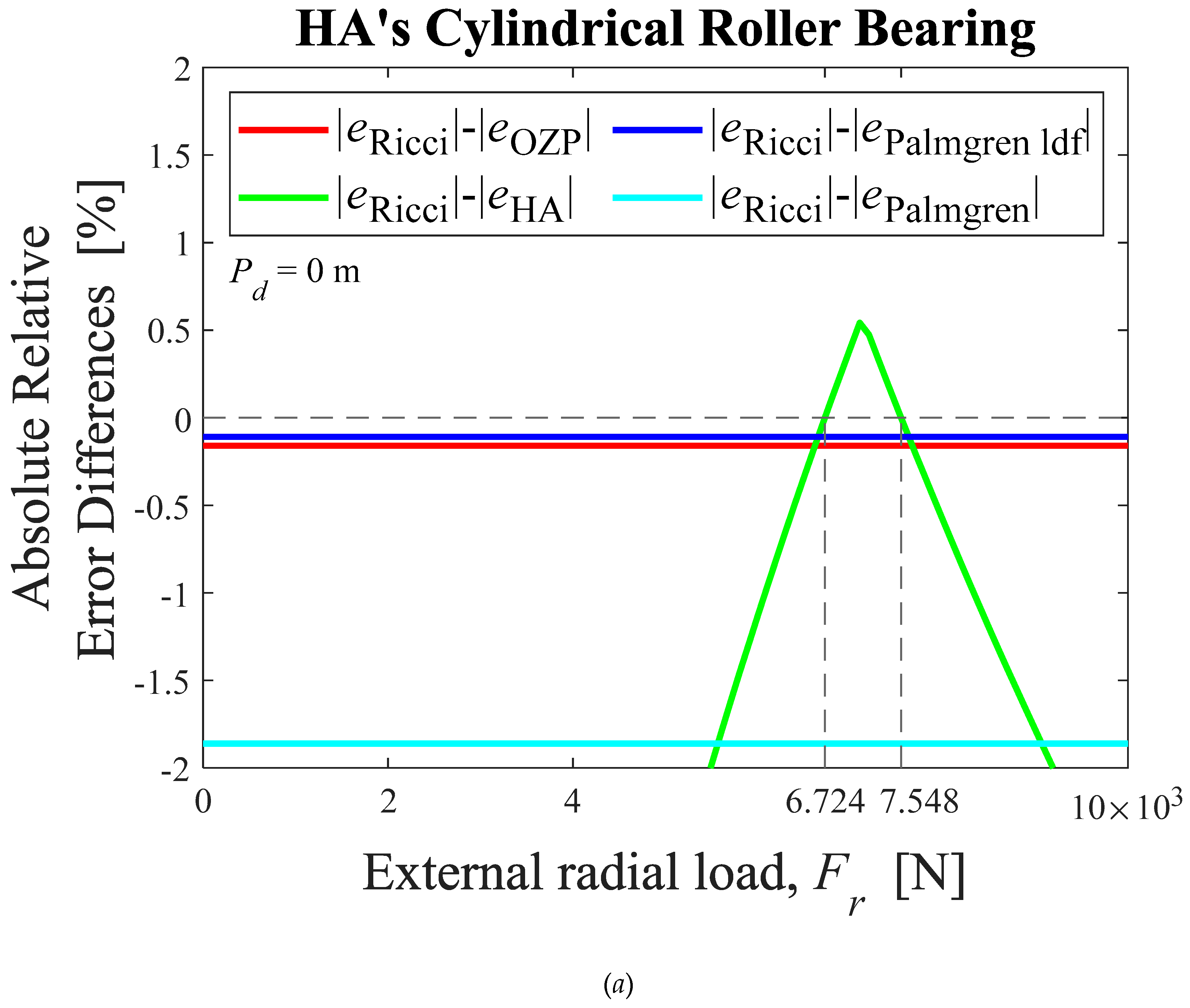

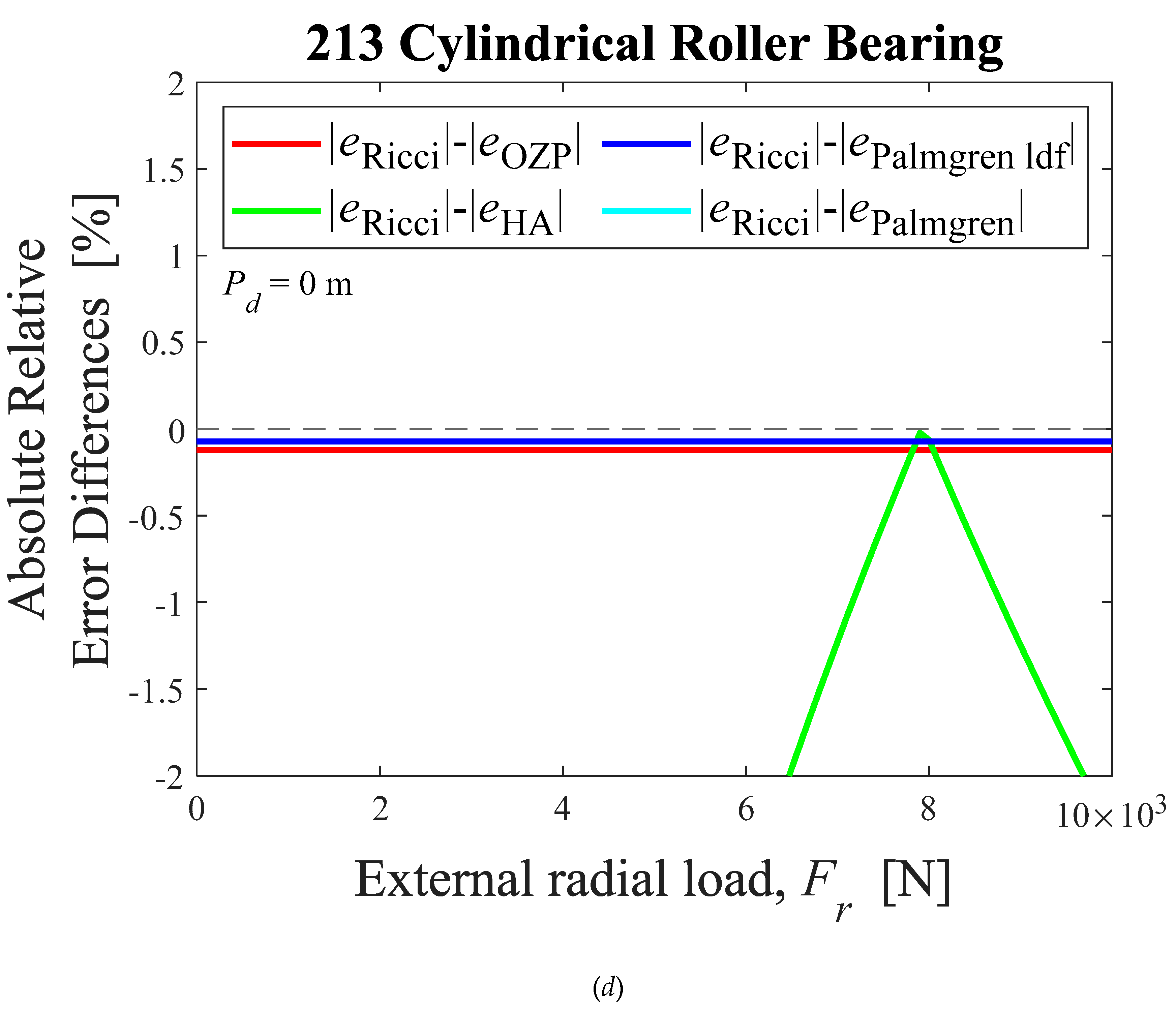
Figure 15.
Numerical solutions of radial displacement of the inner ring with respect to the outer ring, elastic compression on the load line, and normal load on the most loaded ball, obtained by solving iterativelly the equations (35) and (36) with Table I data as input data. (a), (b), and (c): 209; (d), (e), and (f): 210; (g), (h), and (i): 218.
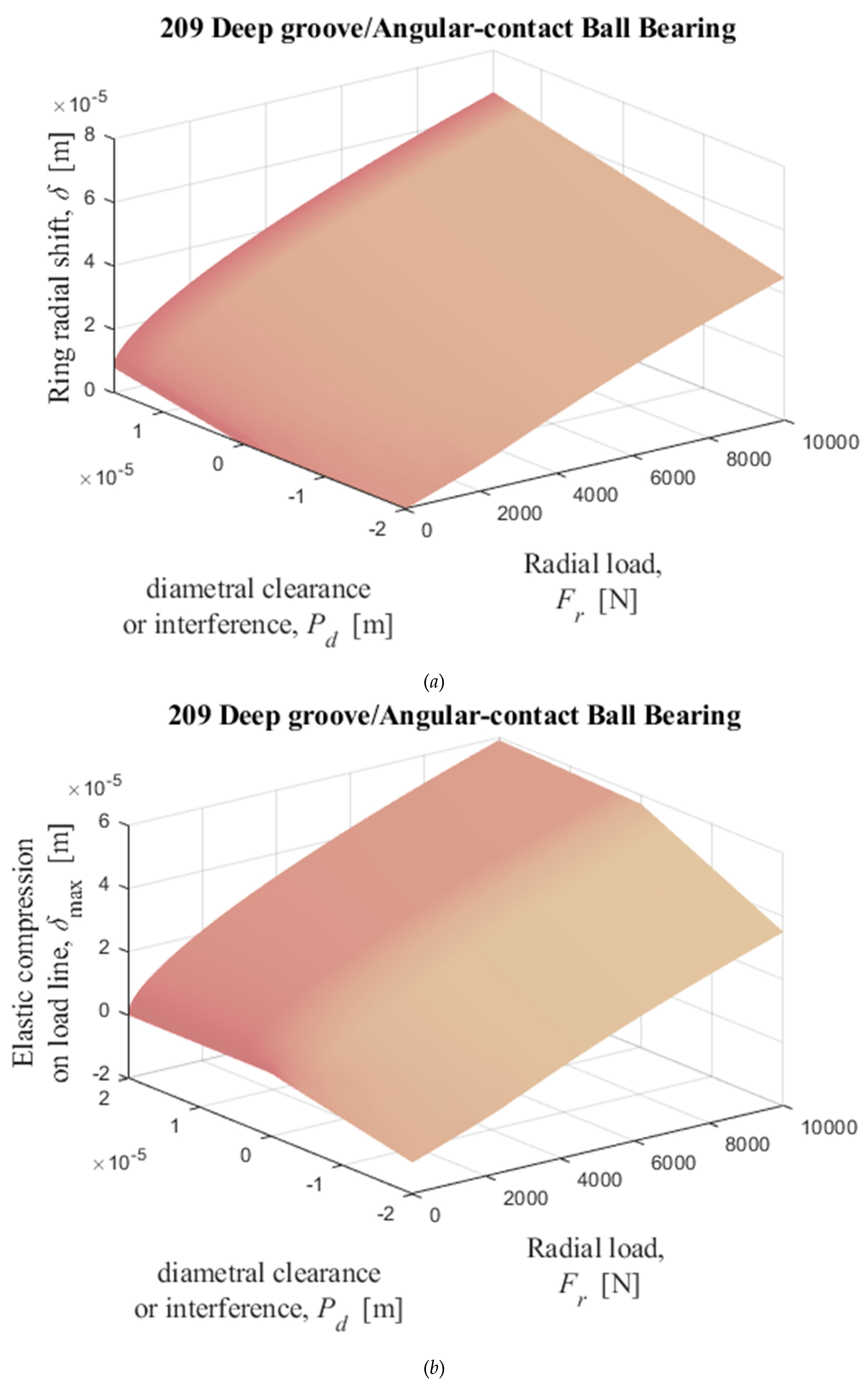
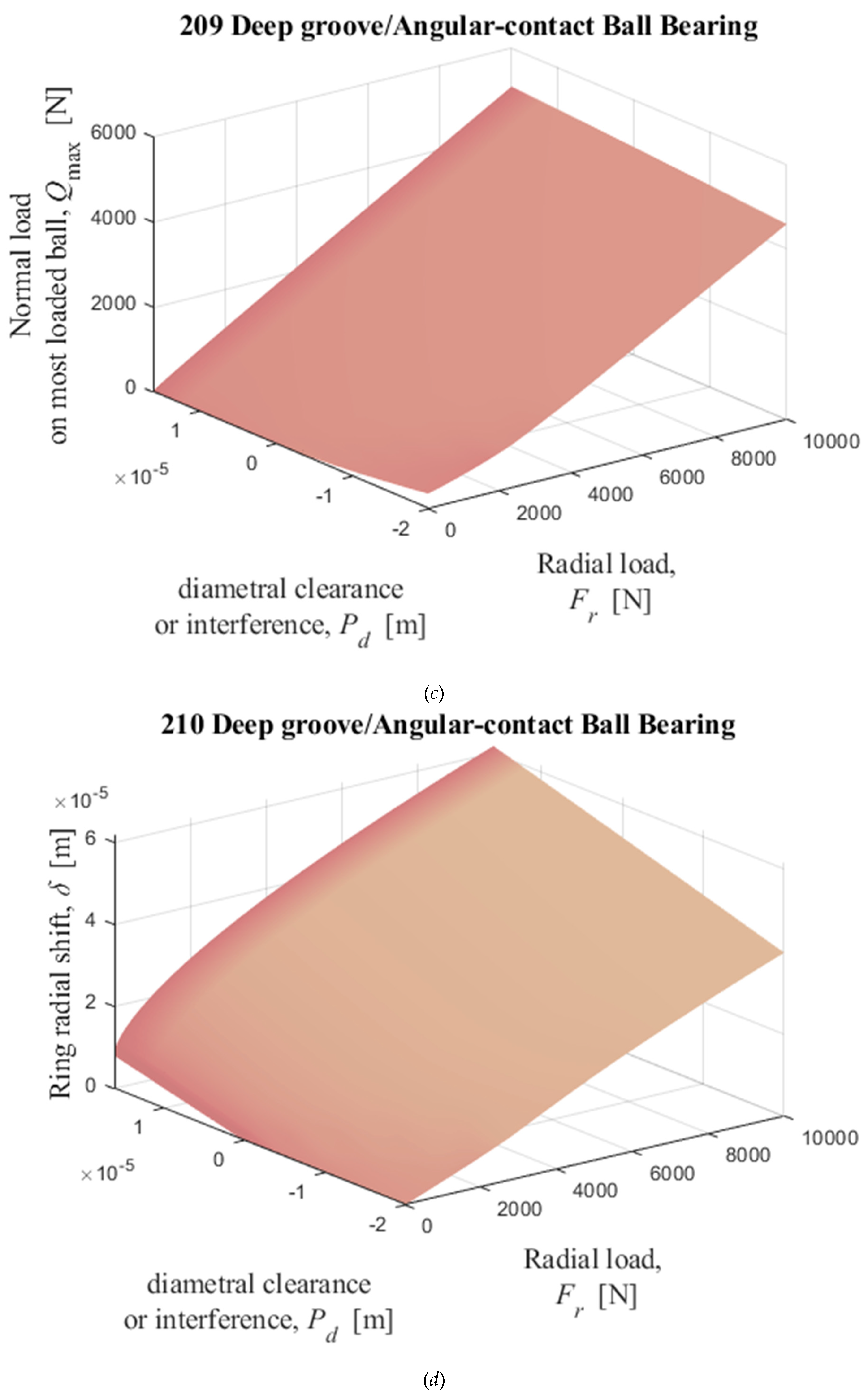
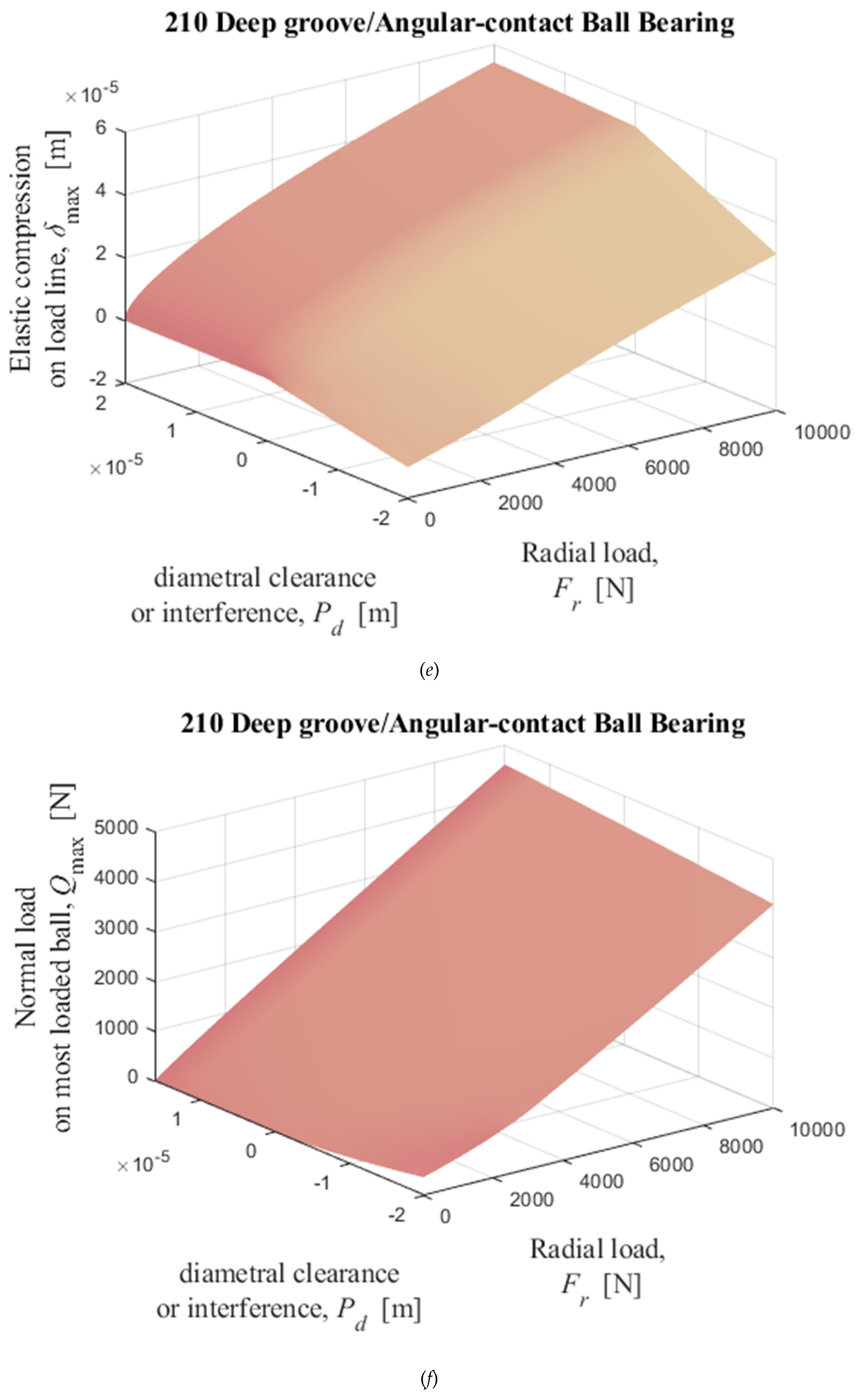
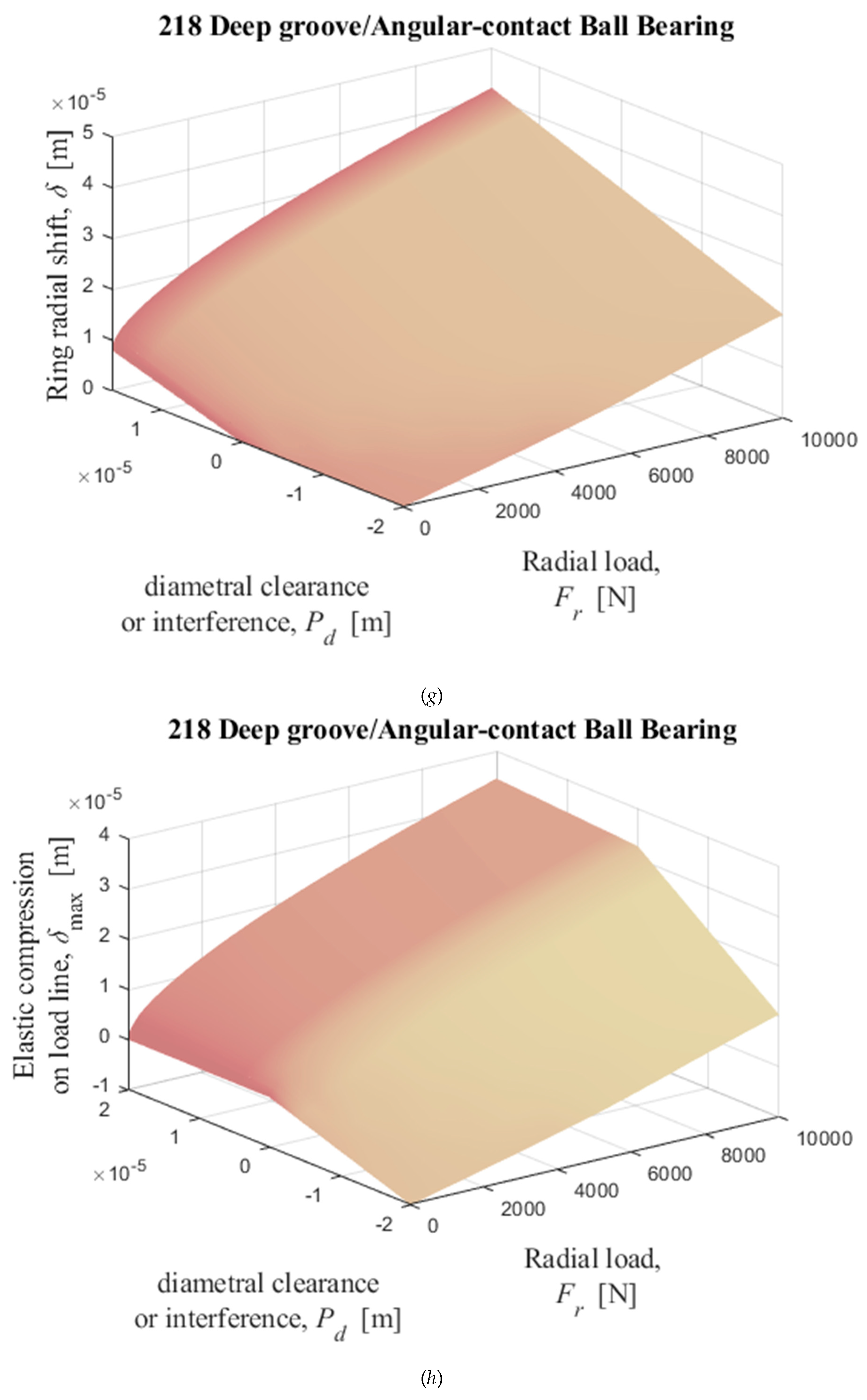
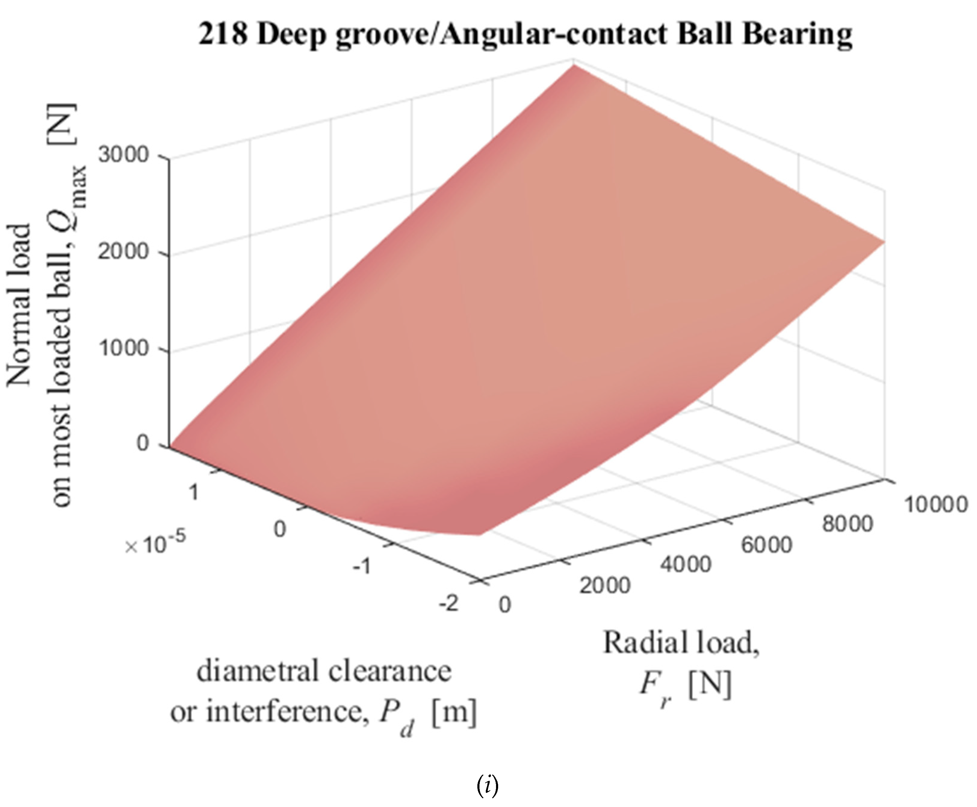
Figure 16.
Numerical solutions of radial displacement of the inner ring with respect to the outer ring, elastic compression on the load line, and normal load on the most loaded cylindrical roller obtained by solving iterativelly the equations (35) and (36) with Table II data as input data. (a), (b), and (c): 205; (d), (e), and (f): 209; (g), (h), and (i): 213.


Disclaimer/Publisher’s Note: The statements, opinions and data contained in all publications are solely those of the individual author(s) and contributor(s) and not of MDPI and/or the editor(s). MDPI and/or the editor(s) disclaim responsibility for any injury to people or property resulting from any ideas, methods, instructions or products referred to in the content. |
© 2023 by the authors. Licensee MDPI, Basel, Switzerland. This article is an open access article distributed under the terms and conditions of the Creative Commons Attribution (CC BY) license (http://creativecommons.org/licenses/by/4.0/).
Copyright: This open access article is published under a Creative Commons CC BY 4.0 license, which permit the free download, distribution, and reuse, provided that the author and preprint are cited in any reuse.


