

Submitted:
27 November 2023
Posted:
28 November 2023
You are already at the latest version
Abstract
This paper shows the development of a numerical analysis model, which enables the calculation of the cargo transport capacity of a vehicle that circulates through a vacuum tube at high speed, whose effectiveness in transport is analyzed. The simulated transportation system is based on vehicles moving in vacuum tubes at high speed, a concept commonly known as Hyperloop, but assuming the vehicles for cargo containers. For the specific vehicle proposed, which does not include a compressor and levitates on magnets, the system formed by the vehicle and the vacuum tube has been conceptually developed, establishing the corresponding mathematical relationships that define its behavior. To properly model the performance of this transport system, it has been necessary to establish the relationships between the design variables and the associated constraints, such as the Kantrowitz limit, aerodynamics, transport, energy consumption, etc. Once the model was built and validated, it was used to analyze the effects of the variation of the number of containers, the operating speed and the tube length, considering the total and specific consumption of energy. Once the most efficient configuration was found regarding energy consumption and transport effectiveness, the complete system was calculated. The results obtained constitute a first approximation for the pre-design of this transport system and the built model allows different alternatives to be compared according to the design variables.
Keywords:
Mathematical modeling
; high-speed transport
; freight transport
; sustainable transport
1. Introduction
The objective of this work is to develop a calculation model that could find the best configuration of a vehicle that transports heavy goods at high speed in a vacuum tube, and thus obtain greater energy efficiency as well as greater effectiveness in the operation of transport. The process consists of defining a case study under behavioral hypotheses, parameterizing the problem through the behavioral equations corresponding to each of the physical phenomena that occur, and applying the analysis to a predesign of a vehicle that simulates the operation in real conditions. Once the behavior relations of the system are established, the energy consumption, the performance of the system, as well as the verification of the Kantrowitz limit, are determined. This allows selecting the optimum amount of load to be transported, the most suitable operating speed, and the most appropriate tube length. Once the optimal values of these variables have been obtained, the rest of the main characteristics of the vehicle are determined.
Regarding the type of system used for vehicle-infrastructure interaction, the authors have considered two options for levitation: air bearings and electrodynamic suspension (EDS). This work focuses on the latter. The vehicle does not include a compressor to overcome the Kantrowitz limit at near-sonic speeds or airfoils [1], [2]; but includes batteries in the rear of the vehicle for the control, and in the EDS rotor. The vehicle also has a mechanical brake for immediate braking in the event of an emergency. It is only considered cargo contained in 20-foot aluminum Dry Van containers and each container must be placed within a single capsule. A linear geometry has been studied, with a straight tube with zero slopes, and which can be 500, 750 or 1,000 km long between origin and destination.
Due to work limitations, other issues such as technical and economic feasibility [3], control loops, stability, infrastructure, vehicle structure, heat transfer, EDS geometry and electrical systems are out of scope and may be eligible for additional work.
This research paper compares to other cutting-edge work on high-speed transportation systems but differs in some respects. These differences are listed next: [4] models a high-speed transportation system and optimizes it, but the system is for passengers instead of cargo and the number of capsules per vehicle is not varied when the energy consumption is minimized. [5] models the system, but it does not use the formulae to optimize the system, as the article is only a technology review. [6] models the system and optimizes it, although the system optimization only focuses on levitation and propulsion (electromechanics) and leaves out the other subsystems. [7], [8] and [9] also model the system, but their model is used to study dynamics, so the system is not optimized, and capacity is not discussed either. [10] discusses transport capacity after building a model, which is based upon logistics relations rather than the physical relations coming from the physical phenomena that occur in the system.
To carry out this research work, it has been necessary to review the behavioral theories of the different physical phenomena involved and the extraction of the corresponding behavioral laws. Likewise, it has been necessary to review the most recent research related to the concept of high-speed transport with vehicles in vacuum tubes. These previous studies provide the necessary equations to define the model of a high-speed transport system. This system is made up of three main subsystems: aerodynamics, electromechanics and thermodynamics. The equations that define the relations and limitations of aerodynamics have been extracted from [11], [12] and [13]. The equations for the electromechanical behavior have been taken from [14], [15] and [16]. The equations related to the thermodynamic phenomena that occur in the system come from [17] and [18].
The main contribution of this work is the determination of the most suitable masses and volumes for freight transport using containers in a vehicle that travels at high speed in a vacuum tube levitating on magnets. Thus, more efficient transportation can be achieved with lower energy consumption per ton and kilometer transported, and greater effectiveness in transportation by establishing the ideal number of containers in cargo movement.
Another contribution to highlight is the analysis procedure, taking into account all of the physical conditions of the problem, and adding the restrictions and limitations of the case to be studied. The result is the variation of the parameters sought. In this case, for example, the optimal weight and volume, which allows finding the most appropriate alternative to the proposed criterion, is aimed at the minimum energy consumption. Once the analysis procedure has been validated, the methodology is open to adding more restrictions and limitations for future research work.
2. Materials and Methods
The methodology applied in this work follows a deductive method, in which, through the construction of the physical problem to be solved, the behavioral equations of the laws of thermodynamics, electromechanics and aerodynamics are applied to the specific case proposed. By establishing the determined limits, the comparison variables that allow an analysis based on the variation of parameters are obtained, and the variation of parameters enables the acquisition of an optimal design. First, the problem to be solved is defined, consisting of establishing the behavior laws of a vehicle levitating on magnets in a vacuum tube to be transported at high speed, for which a series of hypotheses have been proposed. These hypotheses are fundamental to delimit the model of the high-speed transport system, which is defined by the physical equations of its main subsystems: aerodynamics, electromechanics and thermodynamics. Second, these equations are interrelated by auxiliary equations that are introduced later, building a system of equations that is solved by mathematical equation solving software. This software allows to solve the system of equations after configuring the input data. The parameters can be varied in the case study: the calculation is carried out by varying one parameter at a time.
2.1. Hypthoteses
The following hypotheses have been regarded:
- Subsonic speed.
- Ideal gas theory, since the compressibility factor is around 1 under the system working conditions.
- Isentropic compression as the vehicle moves and the air is compelled to flow into the annulus.
- The boundary layer does not separate from the vehicle.
- Both acceleration and deceleration are held constant.
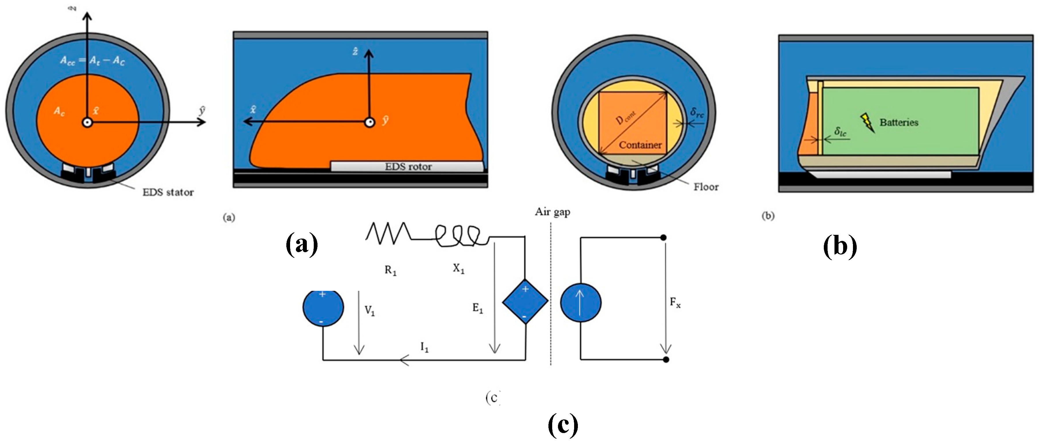
- The frontal area of the EDS magnets is negligible with respect to the annulus area (figure 2 (a)).
- Any lateral forces generated by the propulsion part of the EDS are not considered. These are inherently stabilizing and low with respect to the propulsion force [12].
- Active power losses in the EDS are modeled with a single stator resistance (figure 2 (c)).
- The average power dissipated by the EDS drag is considered one third of the maximum during acceleration and braking. This is because the power dissipated first increases and then decreases with speed [15]. If it were linear with speed, then the average power would be half of the maximum, but in this case, it is less due to that decrease.
- The diameter needed to accommodate the load is equal to the diameter of the circumference surrounding a container (figure 2 (b)).
2.2. Calculation process
An algorithm consisting of three parallel branches that conflate at a point has been constructed:
- In the left branch, the power dissipated by aerodynamic drag is computed. For that, the speed of the vehicle and its thermodynamical data are entered. At that given speed, the tube diameter is calculated so that the Kantrowitz limit is prevented. According to the blockage ratio, the power dissipated by aerodynamic drag is computed.
- In the middle branch, the onboard batteries which feed the rotor of the linear motor are dimensioned. Their dimensioning comes from evaluating their energy density and their discharge time, which depends on the total travel time. In turn, the total travel time relies on the operating speed, acceleration and deceleration of the vehicle through kinematics relations.
- In the right branch, the power needed to propel and lift the vehicle is calculated. This calculus highly relies on the number of containers (that equals the number of capsules in the vehicle) and their individual masses, which depend on the filling factor of each container. These data determine how much mass is lifted and propelled and, thus, the power needed for that.
These branches conflate in order to determine the energy consumption of the vehicle. This way, the energy consumption is linked to the mass transported and to the operating speed, which allows finding relations between the mass flow and the energy needed to maintain that mass flow (always considering that only one vehicle, the one that is to be optimized, is using the tube).
The algorithm is shown in the next flow diagram, which shows how the different equation blocks are interrelated. Equation blocks referring to the main subsystems (aerodynamics, electromechanics and thermodynamics) are represented with a bolded contour, while auxiliary equation blocks are represented with a normal contour. The final block is represented with a doubly-bolded contour:
Figure 1.
Flow diagram of the calculation process (algorithm). Source: Own elaboration.

In this way, it is ensured that the behavior laws of the vehicle inside the tube are fulfilled under all the requirements and considering all the starting hypotheses, with which the physical phenomenon is completely characterized. Once the problem has been formulated, and the behavior equations and the input data are introduced into the software, the software finds the solution to the system of equations. Finally, the design parameters, such as the transported mass, the operating speed, and the length of the tube, are varied according to the simulation procedures. The results (the new results of the system of equations) are obtained in relation to the energy consumption of the transport operation.
2.3. List of abbreviations
The list that contains the abbreviations used in the rest of the article can be consulted in table A1 (appendix A).
2.4. System definition
2.4.1. System drawings
Figure 2.
(a) Cross-sectional drawing of the tube in front of the vehicle and its profile; (b) Cross-sectional drawing of the tube and the vehicle, near the rear, and its axial section; (c) Electrical model for EDS. Source: Own elaboration.
Figure 2.
(a) Cross-sectional drawing of the tube in front of the vehicle and its profile; (b) Cross-sectional drawing of the tube and the vehicle, near the rear, and its axial section; (c) Electrical model for EDS. Source: Own elaboration.
2.4.2. Aerodynamics
The high-speed transport system runs inside a tube, and this is like a vehicle that runs inside a tunnel, whose drag coefficient increases as a result of the tunnel effect. According to [11], the relation between the drag coefficient inside and outside is expressed as follows (Eq. 1). To calculate the coefficient of drag inside, the same reference includes this formula (Eq. 2). Furthermore, the outside drag coefficient is related to the moment section of the boundary layer (Eq. 3):
A relationship exists between the boundary layer momentum section and the boundary layer displacement section. To find this relationship, it must be taken into account that the boundary layer will be laminar, as can be verified by calculating both the local and the global Reynolds number with some data extracted from [19] (first model):
where Pa·s is the dynamic viscosity for dry air at 20 ºC and 100 Pa (the variation of viscosity with pressure is neglectable for such a low pressure) [13]. 25 m is approximately the length of the capsule, which can be gathered from [19]: The passenger capsule levitates on 28 air bearings, 14 on each side and 1.5 m long each (21 m in total, to which other parts as the nose and nozzle are added). With respect to kg/m3, this is the air density and comes from the ideal gas equation.
It can be noted that the local Reynolds is small and not significant, whilst the global can be proper to a laminar boundary layer, since the transition from laminar to turbulent occurs somewhere between and for a flat plate. Assuming that it is always laminar for the high-speed transportation system, von Karman results can be used to relate the momentum thickness to the displacement thickness through the layer thickness. The process is shown below, after collecting the proper information from [13] (Eqs. 6 – 7). The function could be linear, parabolic, polynomial, etc. As a first approximation, the speed profile is assumed to be linear (Eq. 8). After integrating, the following is obtained (Eqs. 9 – 10):
After having gathered all this information, the aerodynamic analysis is solved. Only geometric relations and the generic formula for calculating the drag force remain, which involves density, speed, and frontal area in addition to the drag coefficient inside the tube. All the formulae are shown in the next subsubsections.
2.4.3. Electromechanics
For the study of the EDS, the works consulted are [14], [15] and [16]. The EDS used for this high-speed transportation system is very similar to the one used for maglev vehicles, although in maglev vehicles wheels are needed at low speeds because there is not enough induction magnetic field to levitate. The traditional EDS can be modeled as a LIM (linear induction motor) for levitation and as an LSM (linear synchronous motor) for propulsion. In order to eliminate the need for wheels, the LIM is replaced by an LSM when applying EDS to the high-speed transportation system, where the rotor will be mounted on the pod (short rotor) and the stator on the tube [16]. These two expressions are taken from this work (Eqs. 11 – 12). [15] contains explanations and formulae for levitation and the drag force generated by the EDS operation. Below the formulae can be found, although expressed a little differently (Eqs. 13 – 15). Furthermore, the next equations from [14] have been used in the analysis (Eqs. 16 – 18), where the number three indicates the number of phases of the motor:
The electrical model for EDS is shown in [14]. This model is based on the LSM, which can be seen as a rotary synchronous motor rolled out flat. Subsequently, a resistance and a reactance are used at the stator (on the left). At the model air gap, electric power is equated to mechanical. On the right, a damper and a spring are joined to represent mechanical losses. However, for a first parameter estimation, it is preferable to remove the damper and the spring, and to consider that all active power losses occur in the stator resistance (figure 2 (c)).
Other electrotechnical equations have been used to analyze the EDS. Furthermore, to calculate the thrust required and the power input at the end of acceleration (maximum losses), Newton's second law has been applied.
2.4.4. Thermodynamics
Lastly, to derive the Kantrowitz limit main expression, three basic thermodynamics equations were utilized: Mass flow conservation, Mach number definition, sound speed in an ideal gas, ideal gas law, and isentropic relations for pressure and temperature. The subscript 1 represents the air state variables or associated ones before the air flows into the annulus and the subscript 2 represents the contrary. According to [18], most of the aforementioned formulae may be consulted. The main expression to analyze the Kantrowitz limit phenomenon is derived by combining Eqs, 19 – 25 (subscripts for i=1,2). The complete process can be found in [17] and its outcome is Eq. 26:
Note: . See also figure 2(a) and figure 2(b).
2.4.5. Auxiliary equation block
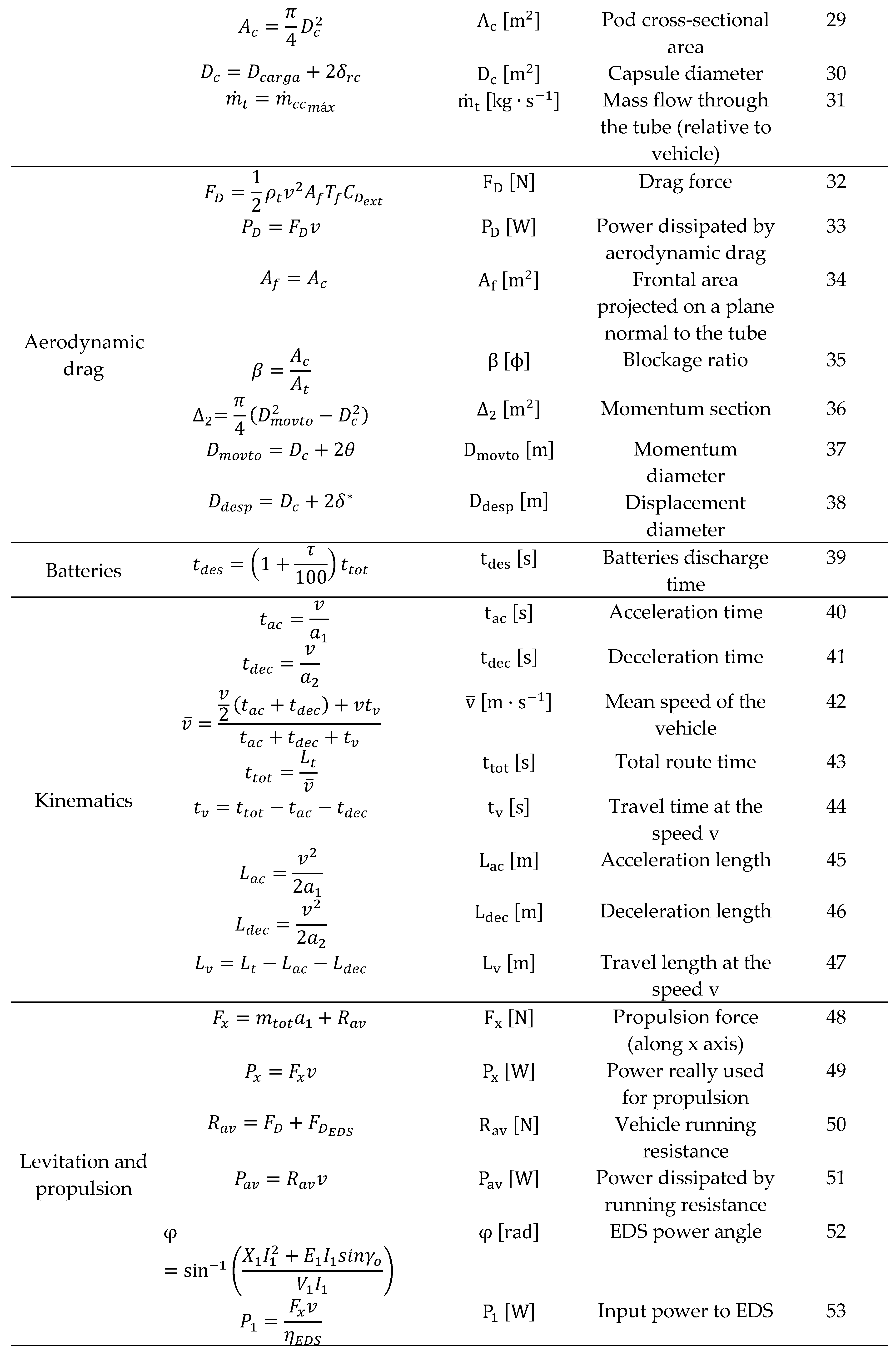
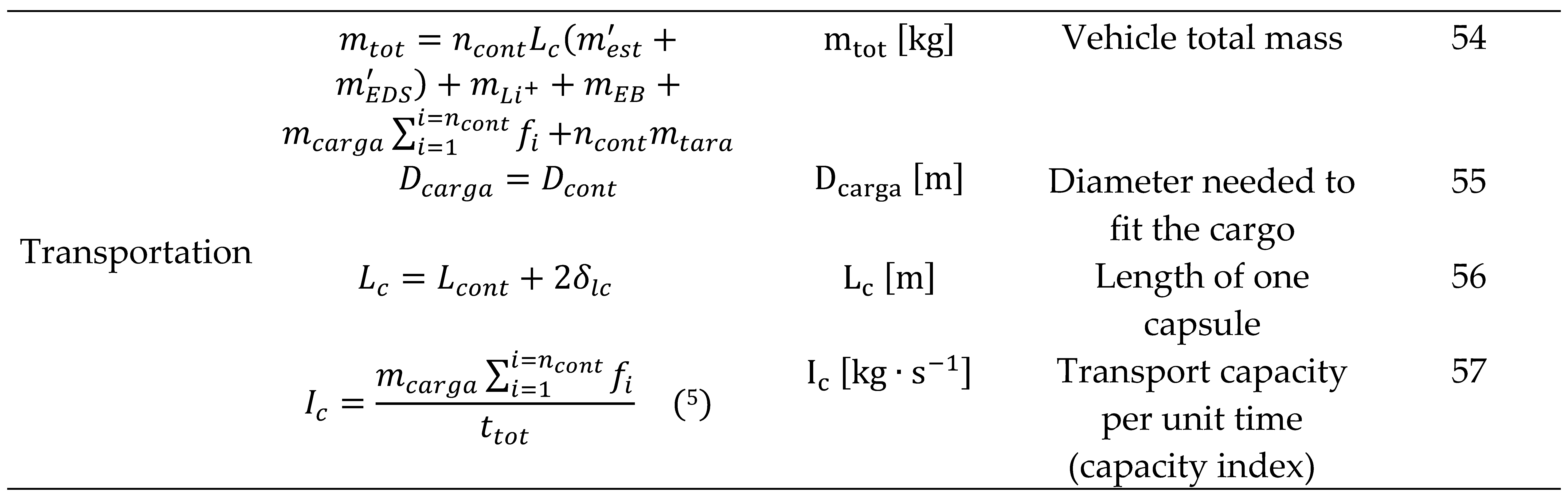
As shown in figure 1, the aerodynamics (Eqs. 1 – 10), electromechanics (Eqs. 11 – 18) and thermodynamics (Eqs. 19 – 26) blocks are interrelated through the auxiliary equation block. This block comprises the Eqs. 27 – 57 and is presented in table B1 (appendix B).
2.4.6. Final equation block
As shown in figure 1, the final block of the model is the energy consumption block. This block comes from [19] and relies on the results of the rest of the blocks. The final block equations are:

Table 1.
Final equation block.
| Block | Equation | Left – side variable [SI unit] | Variable definition | Equation number |
| Energy consumption |
Energy consumed during acceleration | 58 | ||
| Energy generated during deceleration | 59 | |||
| Mean power dissipated by running resistance | 60 | |||
| Energy consumed throughout the travel at the speed v | 61 | |||
| Energy consumed by the batteries | 62 | |||
| Total energy consumed per unit length | 63 | |||
| Total energy per unit length and payload mass | 64 | |||
| Energy consumption per payload mass (energy index) | 65 |
2.5. Software choice
Once all the equations have been obtained, it is necessary to process them in an equation solver program. Due to the large number of equations and relations that had to be implemented, only software capable of processing the entire volume of data in an agile way has been considered. After considering several options (Mathematica, Matlab and Engineering Equation Solver), Engineering Equation Solver [20] has been chosen as it is used in other models that involve thermodynamical equations [21], [22]. The specific version the results were obtained with is Engineering Equation Solver Professional V9.457-3D (EES). The chosen program, besides solving equations, can create parametric tables and graphs derived from those equations.
2.6. Simulation procedures
The objective is to analyze the capacity of this transport system and compare different alternatives based on their efficiency. However, there is a lot of input data to enter before getting the results, that is, the final values of all the output variables involved.
First, input data are chosen. They may come from different sources: references, calculations, and optimizations with the aid of EES tables and graphs in most cases. Then, they are entered in the program.
Once those data have been selected and entered, the number of containers, speed and tube length can be chosen. The choice of these essential factors that are based on the less important factors that we have just selected and introduced is what this work focuses on because they lead to the results. All these results will be obtained for a single vehicle using one of the two tubes, which will be optimized. This vehicle enters the tube, travels through it, and leaves it at the exact instant that a new vehicle begins its journey. After optimization, the results will be extrapolated to a regular transport flow, including the dispatch frequency of the vehicles.
Starting with the number of containers, the most interesting plot to choose is the plot (several curves, one for each number). When selecting it, two factors are key:
- or in other words, specific energy consumption to payload, must be the lowest possible.
- or cargo throughput per unit time must be the highest possible. However, its inverse is used on the plot so that optimal points will fall around the lower-left corner. Seen from another perspective, it can be stated that it is important to minimize the time required to send the payload.
In order to obtain one curve instead of one point with coordinates () for every number of containers, these two basic variables could be altered:
- Speed, which is a relevant factor, as both and strongly depend on it, so a range of speed values is included as input to make the plot. Were the range not included, then the outcome would be one point with coordinates () for every number of containers. The range for a high-speed transportation system without a compressor is 700-1,000 km/h, as will be demonstrated later.
- Tube length. As defined in the beginning, it can take one out of three discrete values: 500, 750 or 1,000 km. and also depend on this to a great extent.
Speed is chosen because the curves as a function of speed will be helpful when selecting it afterward. Choosing the tube length would not have been useful later because the consumption per unit length would not have been represented.
This leads to the choice of speed. curves are used for this, but Kantrowitz limit results are crucial inasmuch as aerodynamics play a huge role. The speed chosen must comply with the following requirements: Working conditions under the Kantrowitz limit while keeping the lowest possible , low and high (or low , its counterpart). Plus, it should leave maglev speeds behind by a sufficient margin.
The most suitable graph for presenting Kantrowitz limit results is the curve. This way, the speed selected will be the one that optimizes and .
After this, the tube length is selected out of the three figures available. This time, is no longer useful on its own. This is because is energy divided by mass, being the factor escalating linearly with (through according to equations 26 – 33 and 53). Were utilized, then 500 km would be optimal for minimizing both and , but energy per unit distance would not even have been considered. Energy per unit distance is relevant because it contributes to determine operation costs. With that said, the unknown is chosen instead of , resulting in curves. may be seen as the combination of and and the optimal length will be the one that minimizes both of them, this being interpreted as pursuing low transportation costs and low operation costs.
Finally, the optimal values for the number of containers, speed and length are introduced. Once the program has compiled everything, the window with the final values will appear on the screen, arranged in alphabetical order.
2.7. Input data
Firstly, 20’ aluminum Dry Van containers have the following characteristics: 6.058 m (≅20') for length (), 2.438 m for width, 2.591 m for height, 2,180 kg for tare (), 28,300 kg for maximum load ().
According to the width and height of the container, the parameter is 3.558 m, using Pythagoras’ theorem.
After setting the dimensions of the specified container, the rest of the input variables are given values:
- (1.5 g). This is because cargo withstands higher accelerations than passengers as there are not any discomfort issues.
- and are constants and the former is null (there is not any wind flowing inside the tube).
- , R, and were extracted from references.
- The rest are optimal [19].
Table 2.
Input variables with their respective units and their values to their right.
| Variable | Value | Variable | Value |
| 14.72 | 2,180 | ||
| 14.72 | 250 | ||
| 3·10-3 | 287 (1) | ||
| 0.60 | 8 | ||
| 0 (const.) | 20 | ||
| 3.558 | 1.40 (2) | ||
| ] | 225 (3) | 15 | |
| 9.81 (const.) | 0.04 | ||
| 6.058 | 0.05 | ||
| 28,300 | 0.90 (4) | ||
| 800* | 0.73 | ||
| 32 | 30 | ||
| 500 | 30 | ||
| 400* |
Note: and 50 kg is added per each additional container. and 250 kg is added per each additional container. 350 and 750 kg have been used to start the series.
3. Results
3.1. curves
The next plot has been created from the data contained in table C1 (appendix C):
Figure 3.
curves for km and for 1 – 5 containers (abbreviated as cont. or conts.).
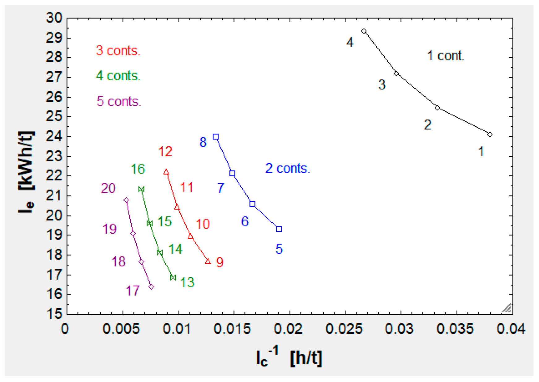
In conclusion, when increasing there is an improvement in both and , which is clearly smaller after every increment.
When adding one container for the first time, payload (associated with capacity) grows by roughly 30 t. This is a 100 % growth, from 30 to 60 t. When adding one container again, payload grows by roughly 30 t with respect to the initial 60. This is a 50 % increase. The next time there is a 33 % increase (30/90) and finally 25 % (30/120). This results in a slowing-pace increase in (the contrary for ).
Besides this, the dead weight also grows increment by increment: and grow as established in table C1, and multiply a longer length ( according to equation 46) and according to the same formula. This and the slowing-pace improvement in capacity explains the slowing-pace decrement in , which is mainly governed by the ratio (the difference between the numerator and denominator is the deadweight) and by losses independent from (chiefly and ) divided by payload.
In the end, is set to 5 because the improvement from 5 to 6 will be predictably tinier and over dimensioning the system is undesirable.
3.2. curve
The next plot has been created from the data contained in table C2 (appendix C):
Figure 4.
curve.
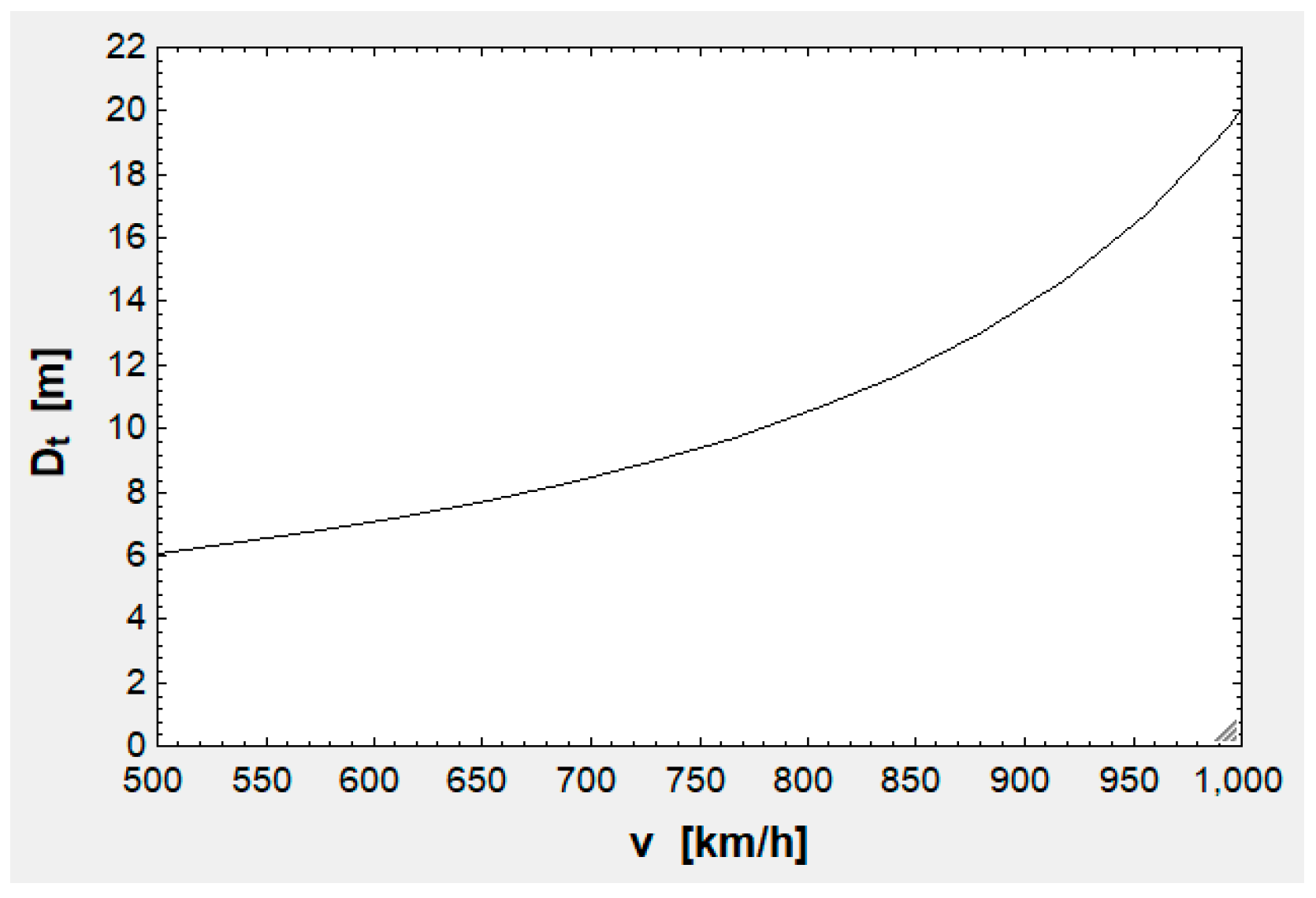
Analyzing figure 4, it can be deduced that the zone of interest goes from 700 to 800 km/h ( around 9 m), these beings the reasons: 9 m is suitable considering that is 3.658 m, so that blockage will be small (0.16 or 16 % at 728 km/h according to table C2); speeds below 700 are near maglev speeds and speeds above 800 yield a rising at a higher rate.
The relevant information provided by figure 3 concerning v is that the ends of any speed range should be avoided: Lowest speeds yield a low , but low (or high ). By contrast, the highest speeds imply the contrary. This means that the optimal speed will be near the center of the speed interval.
With this being said, is chosen as 750 km/h.
3.3. curves
The next plot has been created from the data contained in table C3 (appendix C):
Figure 5.
curves at km/h and for 1 – 5 conts.
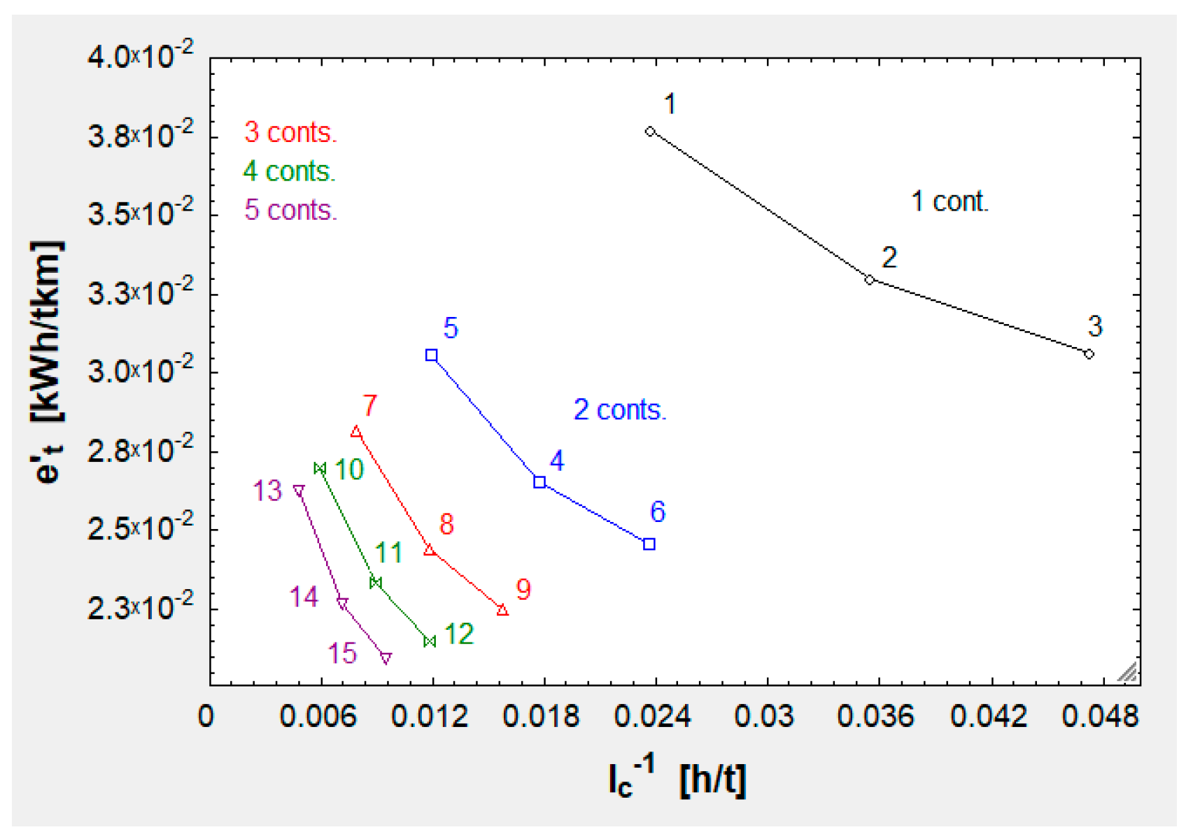
In contrast to the curves, now has replaced . It must be noted that can be calculated as divided by or divided by . This means that all of the tendencies observed before are still valid. Now there are two additional tendencies, explained next.
In the first place, decays as augments, as table C3 proves. This is due to the fact that accelerating the vehicle requires the provision of a high amount of kinetic energy and this energy is better used for longer routes.
Secondly, worsens as grows. It is simple to understand this by reviewing equation 49: As grows, does too and decreases (or increases). Shorter routes allow a higher throughput because for the same period of time more containers can be dispatched.
After having seen the different trends involved, it can be concluded that the best option is km. 750 km (point/run 14 above in figure 5 and table C3) is the only one that optimizes (associated with both and ) and . 500 km (point/run 13) improves and its counterpart but worsens , while 1,000 km (point/run 15) has the contrary effect.
3.1. Definitive results
Once the optimized parameters (, and ) have been introduced, EES solves the whole equation system (the algorithm) provides the definitive results, shown in the following table:
Table 3.
Variables with their respective units and their values to their right.
| Variable | Value | Variable | Value |
| 10.51 | 1,750 | ||
| 58.38 | 32 | ||
| 10.51 | 500 | ||
| 68.89 | 550 | ||
| 14.72 | 42.64 | ||
| 14.72 | 2,180 | ||
| 343.20 | 171,027 | ||
| 3·10-3 | 5 | ||
| 0.60 | 720 | ||
| 1.07 | 1.20 | ||
| 0 | 150,991 | ||
| 3.658 | 1.05 | ||
| 3.558 | 526 | ||
| 3.558 | 250 | ||
| 5.20 | 320.65 | ||
| 4.17 | 287 | ||
| 9.37 | 5,758 | ||
| 63,736 | 8 | ||
| 1,414.39 | 1.78 | ||
| 105.77 | 20 | ||
| -751.50 | 41.60 | ||
| 3.21 | 14.15 | ||
| 1,636.83 | 14.15 | ||
| ] | 225 | 78.31 | |
| 2.27·10-2 | 60.24 | ||
| 724.76 | 59.76 | ||
| 5,033.33 | 97,381 | ||
| 2.52 | 750 | ||
| 1.68 | 11.31 | ||
| 1 | ] | 15.26 | |
| 9.81 | 1.40 | ||
| 2,846 | 15 | ||
| ] | 140.95 | ] | 10.70 |
| 17 | 3.15 | ||
| 1.47 | 0.77 | ||
| 6.138 | 0.04 | ||
| 6.058 | 0.05 | ||
| 1.47 | 0.90 | ||
| 750 | 0.73 | ||
| 747.05 | 0.26 | ||
| 0.61 | ] | 2.97·10-3 | |
| 28,300 | 30 | ||
| 42.64 | 30 |
4. Discussion
A high-speed transportation system (Hyperloop) for freight transport has been pre-designed in this work. It has been found that the most effective configuration is a vehicle with 5 containers moving at 750 km/h in a 750-kilometer tube. This vehicle is capable of delivering 141 t/h with a consumption of 2.27·10-2 kWh/tkm.
However, it is necessary to review certain aspects found when analyzing the predesign.
Firstly, is too large. This is because this vehicle lacks an instrument (like a compressor) to bypass the incoming air. This also impacts speed, since a high-speed transportation system equipped with a compressor is able to reach higher speeds. The authors studied this last case, in which the vehicle levitated on air bearings instead of magnets. The authors found this type of vehicle cannot transport a huge amount of freight because maximum mass flow through the compressor limits pressure under the air bearings and, therefore, payload. Nonetheless, a high-speed transportation system with a compressor levitating on magnets has not been studied yet and is proposed for further works. Moreover, it should also be studied whether or not it is feasible to build a 9-meter diameter tube.
Secondly, and associated with the infrastructure feasibility, there is the EDS feasibility. It should be determined if it is feasible to build a 750-kilometer-long EDS. This EDS system should be able to withstand 720 MW ( in table 3) and evacuate the generated heat (194.40 MW, the 27 % because ). State-of-the-art EDS systems are not likely to withstand such an enormous power. In this case, the first approximation done in this work should be discarded and acceleration reduced. If, for instance, 2.10 (1/7 of 14.72) were to be used, its power would be 103 MW (energy consumption would be virtually the same because acceleration influence on it is infimal). This would negatively impact the mean speed, but 103 MW nears [12]’s results: 50 MW is the traction power for his first model [12] and for his second model it is 87 MW. In any case, the optimization of acceleration and EDS power are two topics proposed for further studies.
In addition to the optimization of EDS power, the materials employed should be as light as possible (for the minimization of ) and the pole pitch should be adjusted to have or even inferior. Thanks to such a good coefficient is only 5 kN ( is greater than 1.5 MN).
Also, it was supposed that grows in 250 kg when does in 30 t. This is simply a first approximation, but this should be further studied. is necessary to prevent the vehicle from crashing catastrophically, but it is dead weight, so it would be desirable to keep at the lowest possible value.
An attempt to lower could be carried out as well. Nowadays there are many composite materials reinforced with advanced fibers (carbon-graphite, aramid, etc.) and alloys (aluminum alloys, for instance) which could lighten the vehicle while resisting the stresses and forces generated.
With respect to the Kantrowitz limit, the vehicle is meant to run at 750 km/h in a 9.37-meter diameter tube and at 20 ºC. At 30 ºC, speed could be slightly raised and at 10 ºC speed should be slightly diminished to avoid the air stacking. If this high-speed transportation system were to run in extremely high or low temperatures, then speed should be diminished or augmented, respectively, although a redesigning process would be more efficient.
Finally, the feasibility of keeping airtightness at 250 Pa should be studied, though it is presumably more feasible than 100 Pa, the pressure proposed by [12]. In relation to this, another proposal is the improvement through CFD simulation or a wind tunnel.
5. Conclusions
Through the mathematical modeling of a novel high-speed transport system based on the use of vacuum tubes, the most convenient design has been obtained which allows an effective freight transport operation, which is also efficient in terms of energy. This effective freight transport operation complies with all of the technical requirements and with all the limitations of the physical problem.
The model allows taking into account all the equations involved by the electromechanical, aerodynamic, and thermodynamic laws present in the definition of the problem. By introducing boundary conditions and starting hypotheses, the model allows an analysis of parametric variation to be carried out.
In the case presented, the optimal number of containers that can be transported at high speed with the lowest possible energy consumption can be obtained as a result, in a technically feasible model.
As a continuation of the research work, the next steps to be carried out will consist of the consideration of solving the problem with the restrictions and difficulties that come with using a tube with different curvatures as infrastructure, and with the existence of slopes along the route.
Supplementary Materials
No supporting information has been uploaded to MDPI.
Author Contributions
Conceptualization, D.P. and E.L.; methodology, D.P.; software, D.P.; validation, D.P. and E.L.; formal analysis, D.P.; investigation, D.P.; resources, D.P. and E.L.; data curation, E.L.; writing—original draft preparation, D.P.; writing—review and editing, E.L.; visualization, D.P.; supervision, E.L.; project administration, E.L.; funding acquisition, E.L. All authors have read and agreed to the published version of the manuscript.
Funding
This research was funded by the UNIVERSITY OF ZARAGOZA.
Data Availability Statement
The data presented in this study are openly available in Mendeley Data at 10.17632/v3w5km6jvv.1 .
Acknowledgments
This research work is a summary of the bachelor thesis previously done by the authors.
Conflicts of Interest
The authors declare no conflict of interest.
Appendix A
Table A1.
List of abbreviations.
| Abbreviation | Definition | Unit (SI) | Abbreviation | Definition | Unit (SI) |
| Pod cross-sectional area | Emergency brakes mass | ||||
| Annulus area | EDS magnets mass per unit length | ||||
| Frontal area projected on a plane normal to the tube | Structural mass per unit length | ||||
| Tube cross-sectional area | Batteries mass | ||||
| Acceleration | Mass flow through the tube (relative to vehicle) | ||||
| Deceleration | Tare of one container | ||||
| Sound speed | Vehicle total mass | ||||
| EDS drag coefficient | Number of containers transported | ||||
| Drag coefficient outside the tube | Input power to EDS | W | |||
| Drag coefficient inside the tube | Power dissipated by running resistance | W | |||
| Wind speed induced inside the tube | Power dissipated by aerodynamic drag | W | |||
| Capsule diameter | Power dissipated by EDS drag | W | |||
| Diameter needed to fit the cargo | Power really used for propulsion | W | |||
| Diameter of the circumference surrounding one container | Pressure inside the tube | ||||
| Displacement diameter | Total pressure inside the tube | ||||
| Momentum diameter | Constant for a certain ideal gas | ||||
| Tube diameter | Vehicle running resistance | ||||
| Phase voltage at the stator after losses | Stator resistance | ||||
| Energy consumed during acceleration | Tunnel factor | ||||
| Energy consumed by the batteries | Temperature inside the tube | ||||
| Energy generated during deceleration | Total temperature inside the tube | ||||
| Total energy consumed per unit length | Acceleration time | ||||
| Energy consumed throughout the travel at the speed v | Deceleration time | ||||
| Battery stored energy per unit mass | Batteries discharge time | ||||
| Total energy per unit length and payload mass | Total route time | ||||
| Drag force | Travel time at the speed v | ||||
| EDS drag force | Phase input voltage to the stator | ||||
| Propulsion force (along x axis) | Vehicle operating speed | ||||
| Levitation force (along z axis) | Stator reactance | ||||
| ) | Blockage ratio | ||||
| Gravity acceleration | Adiabatic index | ||||
| Stator line current | |||||
| Transport capacity per unit time (capacity index) | Displacement section | ||||
| Energy consumption per payload mass (energy index) | Momentum section | ||||
| Acceleration length | Boundary layer displacement thickness | ||||
| Length of one capsule | Pod longitudinal thickness | ||||
| Length of one container | Pod radial thickness | ||||
| Deceleration length | Battery charging efficiency | ||||
| Tube length (same as the route one) | EDS efficiency | ||||
| Travel length at the speed v | Boundary layer momentum thickness | ||||
| Mach number | Density inside the tube | ||||
| Maximum cargo of one container | Percentage of battery duration over travel time | ||||
| Mass flow through the annulus | EDS power angle |
Appendix B
Table B1. Auxiliary equation blocks.

Appendix C
The following table contains the unknowns that were given values to obtain the graphs. v is given four values: 700, 800, 900 and 1,000 km/h. The rest of the input data was compiled by the program as well. It should be noted that all of the power systems are predesigned for the maximum possible payload ( for i = 1, 2, …, 5) because it is the worst-case scenario for the EDS and the power system:
Table C1.
Unknowns given values to obtain the output variables and the plot. The output variables are shown in italics: is for consultation and , for the curves.
Table C1.
Unknowns given values to obtain the output variables and the plot. The output variables are shown in italics: is for consultation and , for the curves.
| Run |
|
|
|
|
|
] |
[km/h] |
[kg] |
[kg] |
|
|
|
|
| 1 | 1 | 1 | 0 | 0 | 0 | 0 | 700 | 350 | 750 | 34,845 | 26.32 | 24.11 | 3.80·10-2 |
| 2 | 1 | 1 | 0 | 0 | 0 | 0 | 800 | 350 | 750 | 34,845 | 30.05 | 25.46 | 3.33·10-2 |
| 3 | 1 | 1 | 0 | 0 | 0 | 0 | 900 | 350 | 750 | 34,845 | 33.77 | 27.19 | 2.96·10-2 |
| 4 | 1 | 1 | 0 | 0 | 0 | 0 | 1,000 | 350 | 750 | 34,845 | 37.47 | 29.36 | 2.67·10-2 |
| 5 | 2 | 1 | 1 | 0 | 0 | 0 | 700 | 400 | 1,000 | 68,891 | 52.65 | 19.29 | 1.90·10-2 |
| 6 | 2 | 1 | 1 | 0 | 0 | 0 | 800 | 400 | 1,000 | 68,891 | 60.10 | 20.58 | 1.66·10-2 |
| 7 | 2 | 1 | 1 | 0 | 0 | 0 | 900 | 400 | 1,000 | 68,891 | 67.54 | 22.15 | 1.48·10-2 |
| 8 | 2 | 1 | 1 | 0 | 0 | 0 | 1,000 | 400 | 1,000 | 68,891 | 74.94 | 24.01 | 1.33·10-2 |
| 9 | 3 | 1 | 1 | 1 | 0 | 0 | 700 | 450 | 1,250 | 102,936 | 78.97 | 17.68 | 1.27·10-2 |
| 10 | 3 | 1 | 1 | 1 | 0 | 0 | 800 | 450 | 1,250 | 102,936 | 90.16 | 18.95 | 1.11·10-2 |
| 11 | 3 | 1 | 1 | 11 | 0 | 0 | 900 | 450 | 1,250 | 102,936 | 101.31 | 20.46 | 9.87·10-3 |
| 12 | 3 | 1 | 1 | 1 | 0 | 0 | 1,000 | 450 | 1,250 | 102,936 | 112.41 | 22.23 | 8.90·10-3 |
| 13 | 4 | 1 | 1 | 1 | 1 | 0 | 700 | 500 | 1,500 | 136,986 | 105.29 | 16.88 | 9.50·10-3 |
| 14 | 4 | 1 | 1 | 1 | 1 | 0 | 800 | 500 | 1,500 | 136,986 | 120.21 | 18.14 | 8.32·10-3 |
| 15 | 4 | 1 | 1 | 1 | 1 | 0 | 900 | 500 | 1,500 | 136,986 | 135.08 | 19.62 | 7.40·10-3 |
| 16 | 4 | 1 | 1 | 1 | 1 | 0 | 1,000 | 500 | 1,500 | 136,986 | 149.89 | 21.33 | 6.67·10-3 |
| 17 | 5 | 1 | 1 | 1 | 1 | 1 | 700 | 550 | 1,750 | 171,027 | 131.62 | 16.40 | 7.60·10-3 |
| 18 | 5 | 1 | 1 | 1 | 1 | 1 | 800 | 550 | 1,750 | 171,027 | 150.26 | 17.65 | 6.66·10-3 |
| 19 | 5 | 1 | 1 | 1 | 1 | 1 | 900 | 550 | 1,750 | 171,027 | 168.84 | 19.12 | 5.92·10-3 |
| 20 | 5 | 1 | 1 | 1 | 1 | 1 | 1,000 | 550 | 1,750 | 171,027 | 187.36 | 20.80 | 5.34·10-3 |
In the table below, only the unknown v is given values. This is because the rest of the values are either constants or optimized ones. The lower limit is 500 km/h, a speed reachable by state-of-the-art maglevs or even high-speed vehicles. The upper one is 1,222 km/h, around the 1,220 km/h proposed by [19]. At 20 ºC and with and , (by means of equation 1), which is slightly superior to 1,222 km/h and means that even if the speed were that, the vehicle would not break the sound barrier and the first hypothesis would still be true:
Table C2.
First, values given to v. And second, the output values for the variables , and , shown in italics.
Table C2.
First, values given to v. And second, the output values for the variables , and , shown in italics.
| Run |
|
|
|
|
Run |
|
|
|
|
| 1 | 500 | 0.40 | 6.05 | 3.65·10-1 | 11 | 880 | 0.71 | 13.02 | 7.90·10-2 |
| 2 | 538 | 0.44 | 6.40 | 3.27·10-1 | 12 | 918 | 0.74 | 14.66 | 6.23·10-2 |
| 3 | 576 | 0.47 | 6.78 | 2.91·10-1 | 13 | 956 | 0.77 | 16.76 | 4.76·10-2 |
| 4 | 614 | 0.50 | 7.22 | 2.57·10-1 | 14 | 994 | 0.80 | 19.52 | 3.51·10-2 |
| 5 | 652 | 0.53 | 7.71 | 2.25·10-1 | 15 | 1,032 | 0.84 | 23.33 | 2.46·10-2 |
| 6 | 690 | 0.56 | 8.28 | 1.95·10-1 | 16 | 1,070 | 0.87 | 28.89 | 1.60·10-2 |
| 7 | 728 | 0.59 | 8.94 | 1.68·10-1 | 17 | 1,108 | 0.90 | 37.78 | 9.37·10-3 |
| 8 | 766 | 0.62 | 9.70 | 1.42·10-1 | 18 | 1,146 | 0.93 | 54.24 | 4.55·10-3 |
| 9 | 804 | 0.65 | 10.61 | 1.19·10-1 | 19 | 1,184 | 0.96 | 95.00 | 1.48·10-3 |
| 10 | 842 | 0.68 | 11.69 | 9.78·10-2 | 20 | 1,222 | 0.99 | 364.88 | 1.01·10-4 |
The following table is a variation of table C1. Here, the column has substituted the v column and there are five fewer runs because adopts three values for each number of containers (15 rows in total):
Table C3.
Input columns, similar to those of table C1 and output columns. The output variables are shown in italics: and are for reference and and serve to elaborate the curves.
Table C3.
Input columns, similar to those of table C1 and output columns. The output variables are shown in italics: and are for reference and and serve to elaborate the curves.
| Run |
|
|
|
|
|
] |
[km] |
[kg] |
[kg] |
[kWh/km] |
[kWh/t] |
[kWh/tkm] |
|
|
| 1 | 1 | 1 | 0 | 0 | 0 | 0 | 500 | 350 | 750 | 1.07 | 18.86 | 3.77·10-2 | 42.20 | 2.37·10-2 |
| 2 | 1 | 1 | 0 | 0 | 0 | 0 | 750 | 350 | 750 | 0.93 | 24.74 | 3.30·10-2 | 28.19 | 3.55·10-2 |
| 3 | 1 | 1 | 0 | 0 | 0 | 0 | 1,000 | 350 | 750 | 0.87 | 30.62 | 3.06·10-2 | 21.16 | 4.73·10-2 |
| 4 | 2 | 1 | 1 | 0 | 0 | 0 | 500 | 400 | 1,000 | 1.73 | 15.28 | 3.06·10-2 | 84.40 | 1.18·10-2 |
| 5 | 2 | 1 | 1 | 0 | 0 | 0 | 750 | 400 | 1,000 | 1.50 | 19.90 | 2.65·10-2 | 56.38 | 1.77·10-2 |
| 6 | 2 | 1 | 1 | 0 | 0 | 0 | 1,000 | 400 | 1,000 | 1.39 | 24.53 | 2.45·10-2 | 42.33 | 2.36·10-2 |
| 7 | 3 | 1 | 1 | 1 | 0 | 0 | 500 | 450 | 1,250 | 2.39 | 14.08 | 2.82·10-2 | 126.60 | 7.90·10-3 |
| 8 | 3 | 1 | 1 | 1 | 0 | 0 | 750 | 450 | 1,250 | 2.07 | 18.29 | 2.44·10-2 | 84.57 | 1.18·10-2 |
| 9 | 3 | 1 | 1 | 1 | 0 | 0 | 1,000 | 450 | 1,250 | 1.91 | 22.50 | 2.25·10-2 | 63.49 | 1.58·10-2 |
| 10 | 4 | 1 | 1 | 1 | 1 | 0 | 500 | 500 | 1,500 | 3.05 | 13.49 | 2.70·10-2 | 168.80 | 5.92·10-3 |
| 11 | 4 | 1 | 1 | 1 | 1 | 0 | 750 | 500 | 1,500 | 2.64 | 17.48 | 2.33·10-2 | 112.76 | 8.87·10-3 |
| 12 | 4 | 1 | 1 | 1 | 1 | 0 | 1,000 | 500 | 1,500 | 2.43 | 21.48 | 2.15·10-2 | 84.65 | 1.18·10-2 |
| 13 | 5 | 1 | 1 | 1 | 1 | 1 | 500 | 550 | 1,750 | 3.72 | 13.13 | 2.63·10-2 | 211.01 | 4.74·10-3 |
| 14 | 5 | 1 | 1 | 1 | 1 | 1 | 750 | 550 | 1,750 | 3.21 | 17.00 | 2.27·10-2 | 140.95 | 7.09·10-3 |
| 5 | 1 | 1 | 1 | 1 | 1 | 1,000 | 550 | 1,750 | 2.95 | 20.87 | 2.09·10-2 | 105.81 | 9.45·10-3 |
| 1 | [23] |
| 2 | [23] |
| 3 | [24] |
| 4 | [24] |
| 5 | This is not the traditional capacity equation. This equation (57) has been specifically engineered for this problem. It assumes that only one vehicle is using the tube at a time, the one which is to be optimized. |
References
- Bizzozero, M.; Yohei Sato,Y.; Sayed, M.A. Aerodynamic study of a Hyperloop pod equipped with compressor to overcome the Kantrowitz limit. Journal of Wind Engineering and Industrial Aerodynamics 2021, 218(1).
- Bose, A.; Viswanathan, V.K. Mitigating the piston effect in high-speed hyperloop transportation: a study on the use of aerofoils. Energies 2021,14(2).
- Hyde, D.J.; Barr, L.C.; Taylor, C. Hyperloop commercial feasibility analysis: High level overview. Resource document, 2016. Available online: https://ia801201.us.archive.org/12/items/HyperloopCommercialFeasibilityReport/Hyperloop_Commercial_Feasibility_Report.pdf (accessed on 4th of November 2023).
- Tudor, D.; Paolone, M. Operational-driven optimal-design of a hyperloop system. Transportation Engineering 2021, 5(1).
- Noland, J. K. Prospects and Challenges of the Hyperloop Transportation System: A Systematic Technology Review. IEEE Access 2021, 9 (1), pp. 28439 – 28458.
- Kisilowski, J.; Kowalik, R. Displacements of the levitation systems in the vehicle hyperloop. Energies 2020, 13(24).
- Bhuiya, M.; Mohiminul Aziz, M. A New Hyperloop Transportation System: Design and Practical Integration. Robotics 2022, 11(1).
- Lee, J.; You, W. Development of the Reduced-Scale Vehicle Model for the Dynamic Characteristic Analysis of the Hyperloop. Energies 2021, 14(13).
- Sadegi, S.; Saeedifard, M.; Bobko, C. Dynamic Modeling and Simulation of Propulsion and Levitation Systems for Hyperloop. In Proceedings of the 13th International Symposium on Linear Drives for Industry Applications, Wuhan, China, 1-3 July 2021. [Google Scholar]
- van Goeverden, K.; Milakis, D.; Janic, M.; Konings, R. Analysis and modelling of performances of the HL (Hyperloop) transport system. European Transport Research Review 2018, 10(41).
- Melis, M.J.; de Matías, I.; Alonso, J.M. Diseño de túneles para trenes de alta velocidad. Rozamiento tren-aire-túnel y ondas de presión. Revista de obras públicas 2001, 148(3415), pp. 27-44.
- Musk, E. Hyperloop Alpha. White paper, 2013. Available online: https://www.tesla.com/sites/default/files/blog_images/hyperloop-alpha.pdf (accessed on 4th of November 2023).
- Schlichting, H; et al. Boundary-Layer Theory, 9th ed; Springer: New York, USA, 2017. [Google Scholar]
- Lever, J.H. Technical Assessment of Maglev System Concepts, Resource document, 1998. Available online: https://rosap.ntl.bts.gov › dot › dot_42287_DS1.pdf (accessed on 4th of November 2023).
- Flankl, M.; Wellerdieck, T.; Tüysüz, A. Scaling laws for electrodynamic suspension in high-speed transportation. IET Electric Power Applications, 12(1) 2018, 357-364.
- Abdelrahman, A.S.; Sayeed, J.M.; Youssef, M.Z. Hyperloop Transportation System: Control, and Drive System Design. In Proceedings of the IEEE Energy Conversion Congress and Exposition, Portland, OR, USA, 23-27 September 2018. [Google Scholar]
- Bar-Meir, G. Fundamentals of Compressible Fluid Mechanics, version 0.4.9.8; published online, 2013. Available online: http://www.bigbook.or.kr/bbs/data/file/bo11/1535291005_vkqPUAtN_Fundamentals_of_Compressible_Fluid_Mechanics_Genick_Bar-Meir.pdf (accessed on 4th of November 2023).
- Mattingly, J.D. Elements of Gas Turbine Propulsion, 1st ed; McGraw-Hill: New York, USA, 1996. [Google Scholar]
- Pellicer, D. S.; Larrodé, E. Conceptual development, analysis and simulation of the transport capacity of a freight transport vehicle in vacuum tubes at high speed (Hyperloop concept). Bachelor thesis, University of Zaragoza, Zaragoza, Spain, 2019. Available online: http://deposita.unizar.es/record/48766 (accessed on 4th of November 2023).
- Klein, S.A. Development and integration of an equation-solving program for engineering thermodynamics courses. Computer Applications in Engineering Education 1993, 1(3), pp. 265-275.
- Tirmizi, S.A.; Gandhidasan, P.; Zubair, S.M. Performance analysis of a chilled water system with various pumping schemes. Applied Energy 2012, 100(1), pp. 238-248.
- Shakouri, M.; Ghadamian, H.; Sheikholeslami, R. Optimal model for multi effect desalination system integrated with gas turbine. Desalination 2010, 260(1-3), 254-263.
- Çengel, Y.A.; Boles, M.A. Thermodynamics: An engineering approach, 8th ed; McGraw-Hill: New York, USA, 2014. [Google Scholar]
- Biswas, M.M.; Azim, M.S.; Saha, T.K. Towards Implementation of Smart Grid: An Updated Review on Electrical Energy Storage Systems. Smart Grid and Renewable Energy 2013, 4(1), pp. 122-132.
Disclaimer/Publisher’s Note: The statements, opinions and data contained in all publications are solely those of the individual author(s) and contributor(s) and not of MDPI and/or the editor(s). MDPI and/or the editor(s) disclaim responsibility for any injury to people or property resulting from any ideas, methods, instructions or products referred to in the content. |
© 2023 by the authors. Licensee MDPI, Basel, Switzerland. This article is an open access article distributed under the terms and conditions of the Creative Commons Attribution (CC BY) license (http://creativecommons.org/licenses/by/4.0/).
Copyright: This open access article is published under a Creative Commons CC BY 4.0 license, which permit the free download, distribution, and reuse, provided that the author and preprint are cited in any reuse.