Submitted:
11 November 2023
Posted:
15 November 2023
You are already at the latest version
Abstract
Keywords:
1. Introduction
1.1. The role of practicable artificial photosynthesis to achieve self-sufficiency in energy security and to solve the CO2 associated global warming problem and the social cost of carbon
1.2. The current status of electricity generating processes from sunlight
1.3. Potential of silicon photovoltaic cell (SPVC) solar panels
1.4. Theoretical setbacks associated with SPVC solar panels

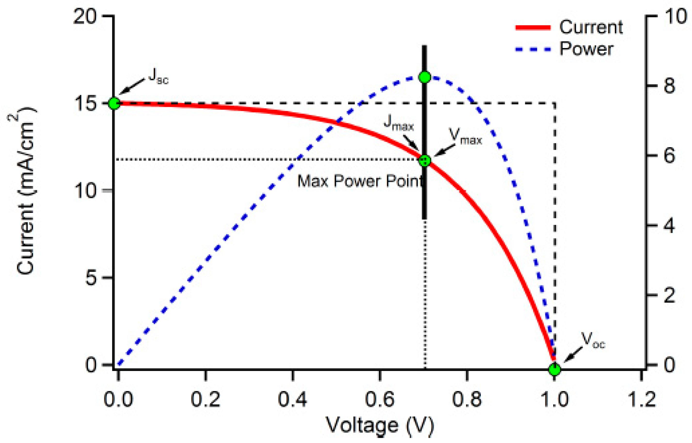
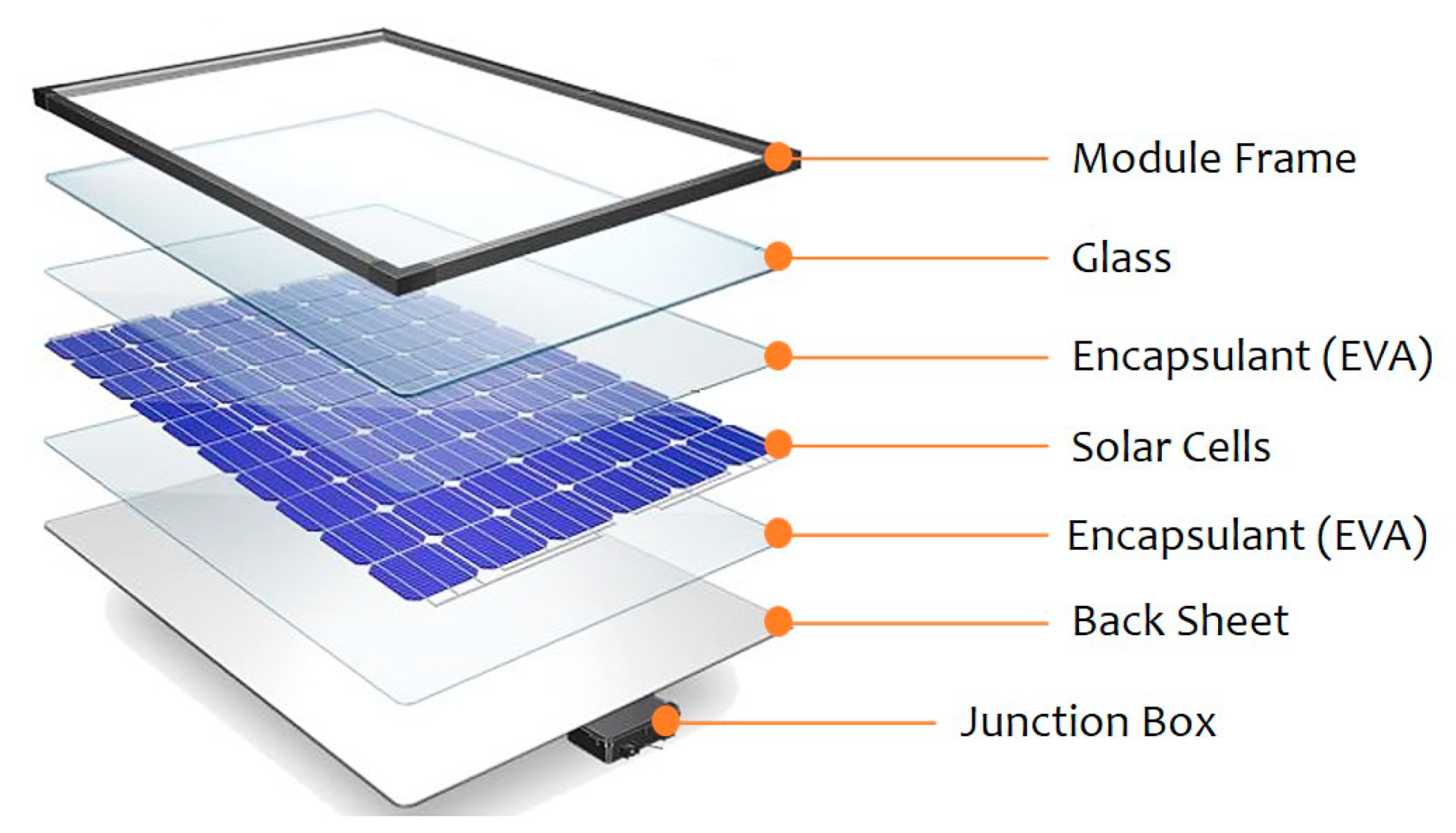
1.5. The environmental concerns of the retired SPVC solar panels
1.6. Is it possible to fully depend on SPVC solar panels to meet all the energy needs of the society without any backup from fossil fuels?
1.7. Semiconductor assisted photothermal effect (SAPE)
1.8. Nanoparticle assisted photothermal effect (NAPE)
1.9. Semiconductor and liquid assisted photothermal effect (SLAPE)
1.10. Transpiration
2. Experimental section
2.1. Fabrication of a SLAPE solar panel
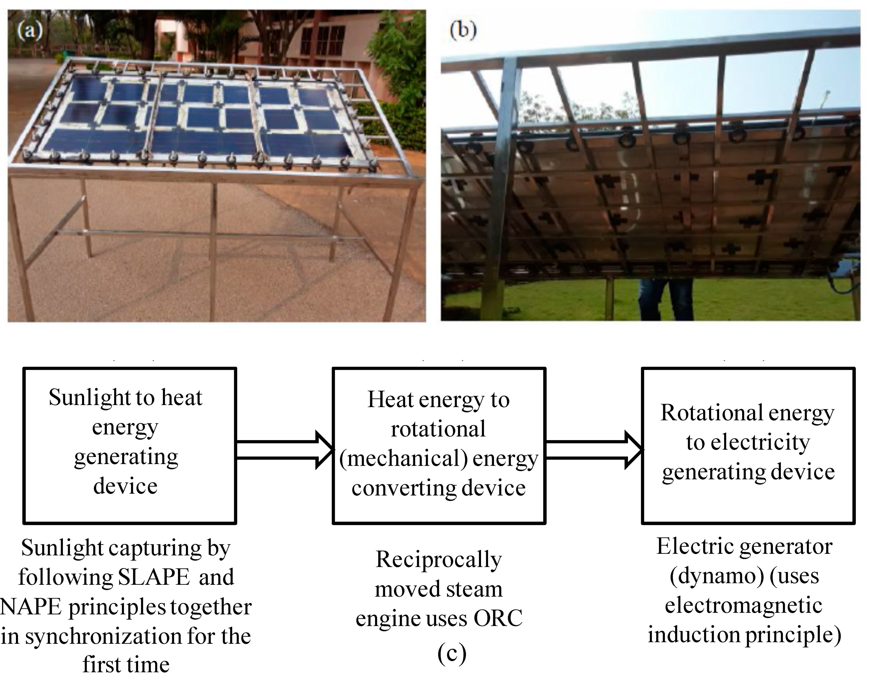
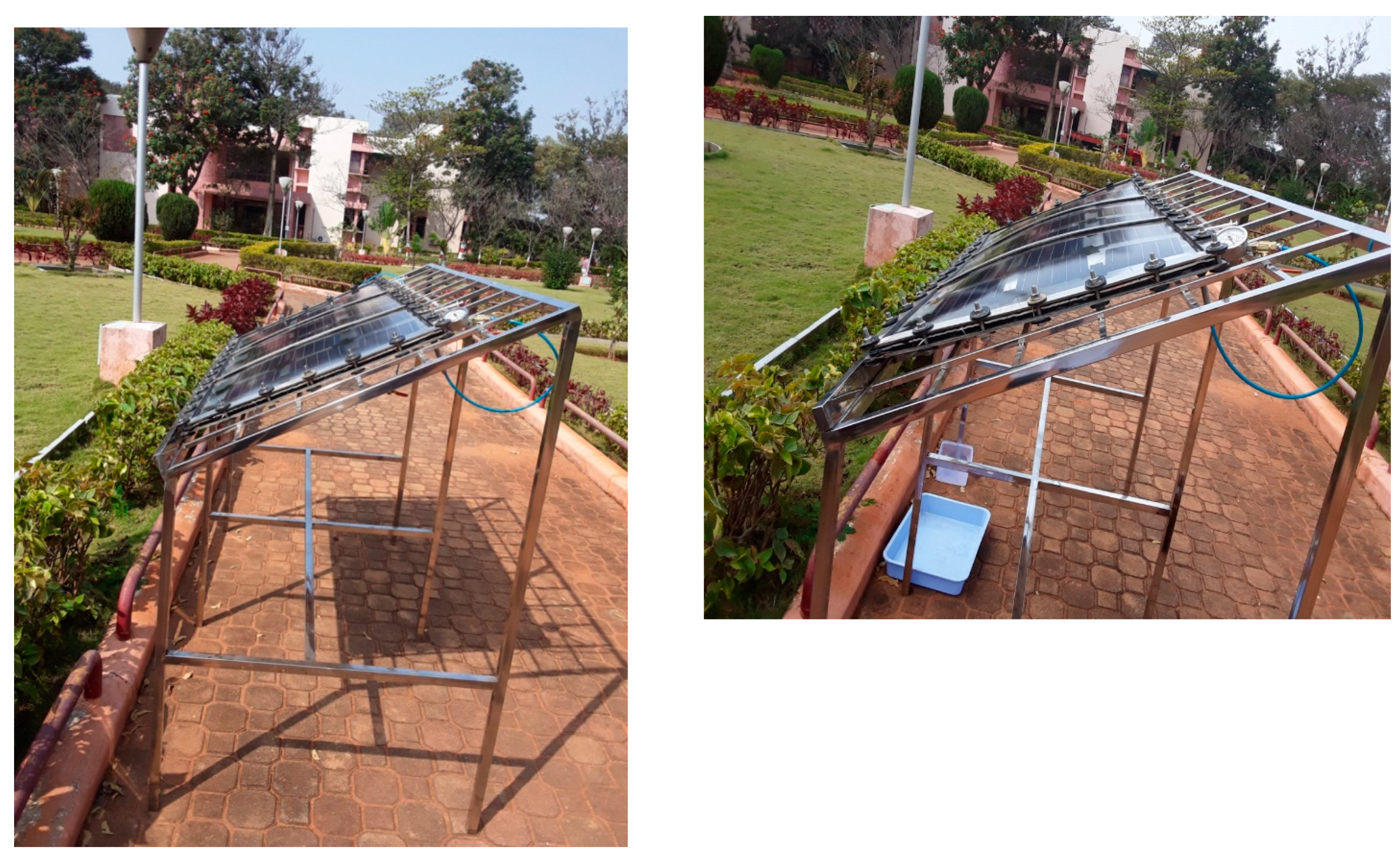
2.2. Fabrication of reciprocally moved steam engine
2.3. Fabrication of electric generator
3. Results and discussion
3.1. Effects of parameters variation on the performance SLAPE solar panels
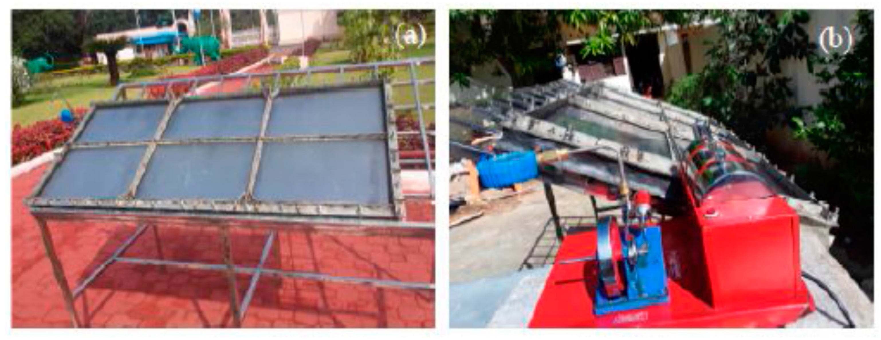
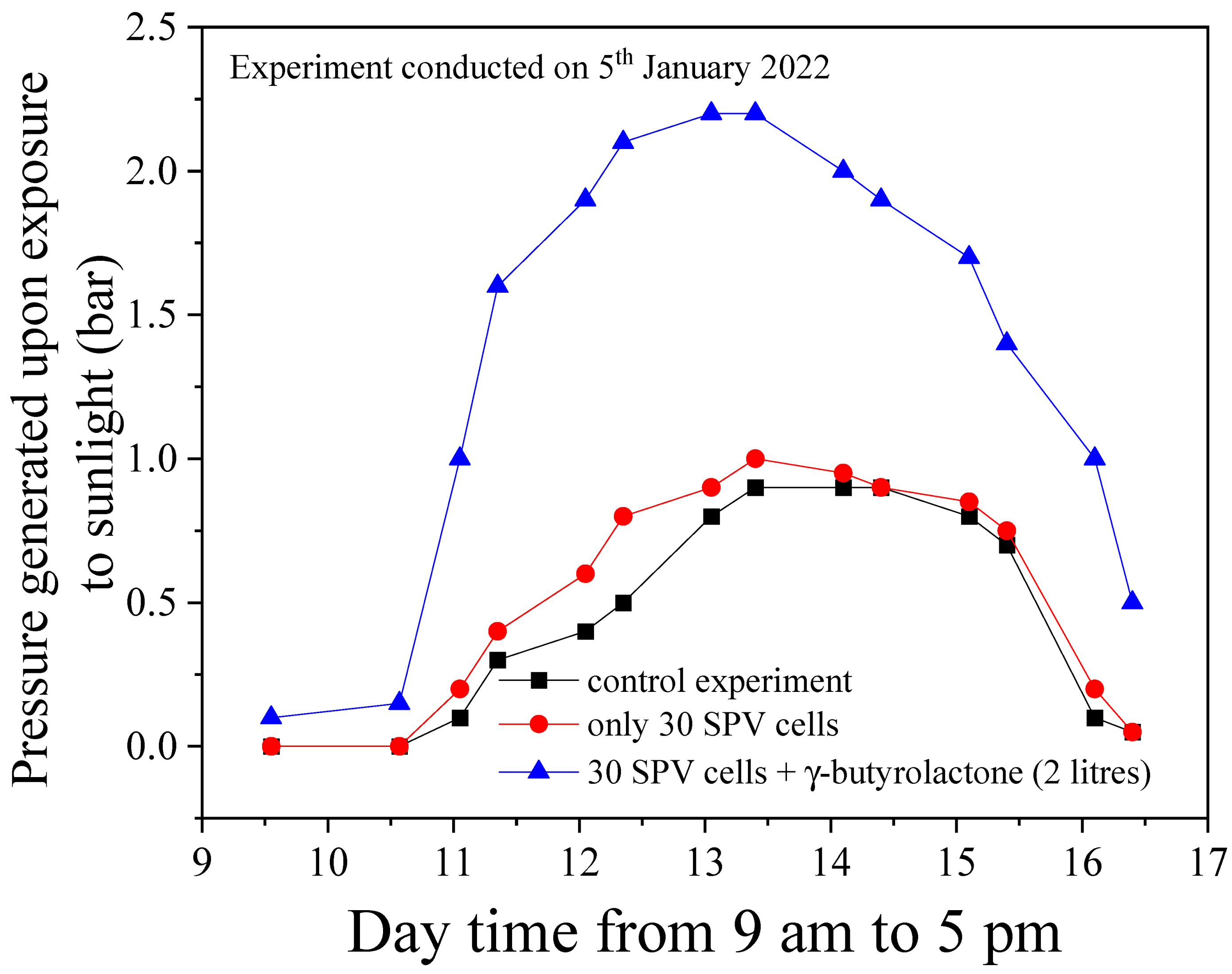
3.2. The theoretical efficiency vs. experimentally generated results
4. Concluding remarks and future perspectives
Acknowledgements
References
- Ganesh, I. (2023) Practicable Artificial Photosynthesis: The Only Option Available Today for Humankind to Make Energy, Environment, Economy and Life Sustainable on Earth, Book published by White Falcon Publishers ISBN Number 978-1-63640-828-6, 1-716.
- Olah, G.A.; Goeppert, A.; Prakash, G.K.S. Chemical recycling of carbon dioxide to methanol and dimethyl ether: from greenhouse gas to renewable, environmentally carbon neutral fuels and synthetic hydrocarbons. J Org Chem 2009, 74, 487–498. [Google Scholar] [CrossRef] [PubMed]
- Olah, G.A. Beyond oil and gas: the methanol economy. Angew Chem Int Ed 2005, 44, 2636–2639. [Google Scholar] [CrossRef]
- Schreier, M.; Curvat, L.; Giordano, F.; Steier, L.; Abate, A.; Zakeeruddin, S.M.; Luo, J.; Mayer, M.T.; Gratzel, M. Efficient photosynthesis of carbon monoxide from CO2 using perovskite photovoltaics. Nat Commun 2015, 6. [Google Scholar] [CrossRef] [PubMed]
- Inoue, T.; Fujishima, A.; Konishi, S.; Honda, K. Photoelectrocatalytic reduction of carbon dioxide in aqueous suspensions of semiconductor powders. Nature 1979, 277, 637–638. [Google Scholar] [CrossRef]
- Barton, E.E.; Rampulla, D.M.; Bocarsly, A.B. Selective solar-driven reduction of CO2 to methanol using a aatalyzed p-GaP based photoelectrochemical cell. J Am Chem Soc 2008, 130, 6342–6344. [Google Scholar] [CrossRef]
- Seshadri, G.; Lin, C.; Bocarsly, A.B. A new homogeneous electrocatalyst for the reduction of carbon dioxide to methanol at low overpotential. J Electroanal Chem 1994, 372, 145–150. [Google Scholar] [CrossRef]
- Haas, T.; Krause, R.; Weber, R.; Demler, M.; Schmid, G. Technical photosynthesis involving CO2 electrolysis and fermentation. Nat Catal 2018, 1, 32–39. [Google Scholar] [CrossRef]
- Handoko, A.D.; Wei, F.; Jenndy, Y.B.S.; Seh, Z.W. Understanding heterogeneous electrocatalytic carbon dioxide reduction through operando techniques. Nat Catal 2018, 1, 922–34. [Google Scholar] [CrossRef]
- 10] Centi G, Perathoner S. CO2-based energy vectors for the storage of solar energy. Greenhouse Gas Sci Technol 2011, 1, 21.
- Centi, G.; Perathoner, S. Towards solar fuels from water and CO2. ChemSusChem 2010, 3, 195–208. [Google Scholar] [CrossRef]
- Centi, G.; Perathoner, S. Opportunities and prospects in the chemical recycling of carbon dioxide to fuels. Catal Today 2009, 148, 191–205. [Google Scholar] [CrossRef]
- Medina-Ramos, J.; Pupillo, R.C.; Keane, T.P.; DiMeglio, J.L.; Rosenthal, J. Efficient conversion of CO2 to CO using tin and other inexpensive and easily prepared post-transition metal catalysts. J Am Chem Soc 2015, 137, 5021–5027. [Google Scholar] [CrossRef] [PubMed]
- Medina-Ramos, J.; DiMeglio, J.L.; Rosenthal, J. Efficient reduction of CO2 to CO with high current density using in situ or ex situ prepared Bi-based materials. J Am Chem Soc 2014, 136, 8361–8367. [Google Scholar] [CrossRef] [PubMed]
- Asadi, M.; Kumar, B.; Behranginia, A.; Rosen, B.A.; Baskin, A.; Repnin, N.; Pisasale, D.; Phillips, P.; Zhu, W.; Haasch, R.; Klie, R.F.; Král, P.; Abiade, J.; Salehi-Khojin, A. Robust carbon dioxide reduction on molybdenum disulphide edges. Nat Commun 2014, 5. [Google Scholar] [CrossRef] [PubMed]
- Rosen, B.A.; Haan, J.L.; Mukherjee, P.; Braunschweig, B.; Zhu, W.; Salehi-Khojin, A.; Dlott, D.D.; Masel, R.I. In situ spectroscopic examination of a low overpotential pathway for carbon dioxide conversion to carbon monoxide. J Phys Chem C 2012, 116, 15307–15312. [Google Scholar] [CrossRef]
- Rosen, B.A.; Salehi-Khojin, A.; Thorson, M.R.; Zhu, W.; Whipple, D.T.; Kenis, P.J.A.; Masel, R.I. Ionic liquid–mediated selective conversion of CO2 to CO at low overpotentials. Sci 2011, 334, 643–644. [Google Scholar] [CrossRef] [PubMed]
- Ganesh, I. BMIM-BF4 RTIL: synthesis, characterization and performance evaluation for electrochemical CO2 reduction to CO over Sn and MoSi2 cathodes. C - J Carbon Res 2020, 6, 47. [Google Scholar] [CrossRef]
- Ganesh, I. BMIM–BF4 mediated electrochemical CO2 reduction to CO is a reverse reaction of CO oxidation in air—experimental evidence. J Phys Chem C 2019, 123, 30198–30212. [Google Scholar] [CrossRef]
- Ganesh, I. Chapter 4 - the electrochemical conversion of carbon dioxide to carbon monoxide over nanomaterial based cathodic systems: measures to take to apply this laboratory process industrially. In Applications of Nanomaterials (Mohan Bhagyaraj, S., Oluwafemi, O. S., Kalarikkal, N., and Thomas, S., Eds.), Woodhead Publishing, 2018, 83.
- Ganesh, I. Electrochemical conversion of carbon dioxide into renewable fuel chemicals – The role of nanomaterials and the commercialization. Renew Sustain Energy Rev 2016, 59, 1269–1297. [Google Scholar] [CrossRef]
- Ganesh, I. Solar fuels vis-a´-vis electricity generation from sunlight: the current state-of-the-art (a review). Renew Sustain Energy Rev 2015, 44, 904–932. [Google Scholar] [CrossRef]
- Ganesh, I.; Kumar, P.P.; Annapoorna, I.; Sumliner, J.M.; Ramakrishna, M.; Hebalkar, N.Y.; Padmanabham, G.; Sundararajan, G. Preparation and characterization of Cu-doped TiO2 materials for electrochemical, photoelectrochemical, and photocatalytic applications. Appl Surf Sci 2014, 293, 229–47. [Google Scholar] [CrossRef]
- Ganesh, I. Conversion of carbon dioxide into methanol – a potential liquid fuel: Fundamental challenges and opportunities (a review). Renew Sustain Energy Rev 2014, 31, 221–257. [Google Scholar] [CrossRef]
- Ganesh, I. Conversion of carbon dioxide into several potential chemical commodities following different pathways-a review. Mater Sci Forum 2013, 764, 1–82. [Google Scholar] [CrossRef]
- Zeng, K.; Zhang, D. Recent progress in alkaline water electrolysis for hydrogen production and applications. Prog Energy Combus Sci 2010, 36, 307–326. [Google Scholar] [CrossRef]
- Wikipedia. World energy consumption. 15th September 2017.
- Wikipedia. Energy policy of India. 15th September 2017.
- https://www.eia.gov/outlooks/ieo/pdf/0484(2016).pdf (Chapter 1. World energy demand and economic outlook).
- www.eia.gov/ieo. (International Energy Outlook 2017).
- Centi, G.; Perathoner, S. Nanocatalysis: a key role for sustainable energy future. In Nanotechnology in Catalysis, Wiley-VCH Verlag GmbH & Co. KGaA, 2017, 383-400.
- Zhang, S.; Sun, J.; Zhang, X.; Xin, J.; Miao, Q.; Wang, J. Ionic liquid-based green processes for energy production. Chem Soc Rev 2014, 43, 7838–7869. [Google Scholar] [CrossRef] [PubMed]
- Budzianowski, W.M. Negative carbon intensity of renewable energy technologies involving biomass or carbon dioxide as inputs. Renew Sustain Energy Rev 2012, 16, 6507–6521. [Google Scholar] [CrossRef]
- Budzianowski, W.M. Value-added carbon management technologies for low CO2 intensive carbon-based energy vectors. Energy 2012, 41, 280–297. [Google Scholar] [CrossRef]
- Maag, G.; Steinfeld, A. Design of a 10 MW particle-flow reactor for syngas production by steam-gasification of carbonaceous feedstock using concentrated solar energy. Energy Fuels 2010, 24, 6540–6547. [Google Scholar] [CrossRef]
- Klein, A.; Koerber, C.; Wachau, A.; Saeuberlich, F.; Gassenbauer, Y.; Harvey, S.P.; Proffit, D.E.; Mason, T.O. Transparent conducting oxides for photovoltaics: manipulation of Fermi level, work function and energy band alignment. Mater 2010, 3, 4892–4914. [Google Scholar] [CrossRef] [PubMed]
- Garcia-Martinez, J. Nanotechnology for the Energy Challenge. Wiley-VCH Weinheim, Germany, 2010.
- Cheng, Y.H.; Nguyen, V.H.; Chan, H.Y.; Wu, J.C.S.; Wang, W.H. Photo-enhanced hydrogenation of CO2 to mimic photosynthesis by CO co-feed in a novel twin reactor. Appl Energy 2015, 147, 318–324. [Google Scholar] [CrossRef]
- Ganesh, I. The latest state-of-the-art on artificial photosynthesis. Chem Express 2014, 3, 131–148. [Google Scholar]
- Smieja, J.M.; Benson, E.E.; Kumar, B.; Grice, K.A.; Seu, C.S.; Miller, A.J.M.; Mayer, J.M.; Kubiak, C.P. Kinetic and structural studies, origins of selectivity, and interfacial charge transfer in the artificial photosynthesis of CO. Proc Natl Acad Sci USA 2012, 109, 15646–15650. [Google Scholar] [CrossRef] [PubMed]
- Concepcion, J.J.; House, R.L.; Papanikolas, J.M.; Meyer, T.J. Chemical approaches to artificial photosynthesis. Proc Natl Acad Sci USA 2012, 109, 15560–15564. [Google Scholar] [CrossRef] [PubMed]
- Nazimek, D.; Czech, B. Artificial photosynthesis - CO2 towards methanol. IOP Conf Ser: Mater Sci Eng 2011, 19.
- Yang, C.C.; Yu, Y.H.; van der Linden, B.; Wu, J.C.; Mul, G. Artificial photosynthesis over crystalline TiO2-based catalysts: fact or fiction? J Am Chem Soc 2010, 132, 8398–8406. [Google Scholar] [CrossRef] [PubMed]
- Hammarström, L.; Hammes-Schiffer, S. Guest editorial: artificial photosynthesis and solar fuels. Acc Chem Res 2009, 42, 1859–1860. [Google Scholar] [CrossRef] [PubMed]
- Gust, D.; Moore, T.A.; Moore, A.L. Solar Fuels via Artificial Photosynthesis. Acc Chem Res 2009, 42, 1890–1898. [Google Scholar] [CrossRef] [PubMed]
- Gratzel, M.; Kalyanasundaram, K. Artificial photosynthesis: efficient dye-sensitized photoelectrochemical cells for direct conversion of visible light to electricity. Curr Sci 1994, 66, 706–714. [Google Scholar]
- Hynninen, P.H. Functions of chlorophylls in photosynthesis. Kem Kemi 1990, 17, 241–249. [Google Scholar]
- https://www.ndtv.com/chennai-news/2015-chennai-floods-a-man-made-disaster-says-cag-report-1881906.
- https://en.wikipedia.org/wiki/2018_Kerala_floods.
- Wamsler, C.; Schäpke, N.; Fraude, C.; Stasiak, D.; Bruhn, T.; Lawrence, M.; Schroeder, H.; Mundaca, L. Enabling new mindsets and transformative skills for negotiating and activating climate action: lessons from UNFCCC conferences of the parties. Environ Sci Policy 2020, 112, 227–235. [Google Scholar] [CrossRef] [PubMed]
- Sorkar, M.N.I. Framing shaping outcomes: issues related to mitigation in the UNFCCC negotiations. Fudan J Human Social Sci 2020, 13, 375–394. [Google Scholar] [CrossRef]
- Prys-Hansen, M. Differentiation as affirmative action: transforming or reinforcing structural inequality at the UNFCCC? Global Soc 2020, 34, 353–369. [Google Scholar] [CrossRef]
- Oh, C. Discursive contestation on technological innovation and the institutional design of the UNFCCC in the new climate change regime. New Political Economy 2020, 25, 660–674. [Google Scholar] [CrossRef]
- Broberg, M. Interpreting the UNFCCC’s provisions on ‘mitigation’ and ‘adaptation’ in light of the Paris Agreement’s provision on ‘loss and damage’. Climate Policy 2020, 20, 527–533. [Google Scholar] [CrossRef]
- Teng, Y.; Zhang, D. Long-term viability of carbon sequestration in deep-sea sediments. Sci Adv 2018, 4, eaao6588. [Google Scholar] [CrossRef] [PubMed]
- Sanna, A.; Uibu, M.; Caramanna, G.; Kuusik, R.; Maroto-Valer, M.M. A review of mineral carbonation technologies to sequester CO2. Chem Soc Rev 2014, 43, 8049–8080. [Google Scholar] [CrossRef]
- Zhu, X.; Hatzell, M.C.; Logan, B.E. Microbial reverse-electrodialysis electrolysis and chemical-production cell for H2 production and CO2 sequestration. Environ Sci Tech Lett 2014, 1, 231–235. [Google Scholar] [CrossRef]
- Hustad, C.W. Infrastructure for CO2 collection, transport and sequestration. Trondheim presented at the 3rd Nordic mini-symposium on carbon dioxide storage 2003. [Google Scholar]
- Gale, J. Using coal seams for CO2 sequestration. Geologica Belgica 2004, 7. [Google Scholar]
- Bachu, S.; Adams, J.J. Sequestration of CO2 in geological media in response to climate change: capacity of deep saline aquifers to sequester CO2 in solution. Energy Conver Manage 2003, 44, 3151. [Google Scholar] [CrossRef]
- Bachu, S. Sequestration of CO2 in geological media: criteria and approach for site selection in response to climate change. Energy Conver Manage 2000, 41, 953. [Google Scholar] [CrossRef]
- MatterJM, Stute M, Snæbjörnsdottir SÓ, Oelkers EH, Gislason SR, Aradottir ES, Sigfusson B, Gunnarsson I, Sigurdardottir H, Gunnlaugsson E, Axelsson G, Alfredsson HA, Wolff-Boenisch D, Mesfin K, Taya DFDLR, Hall J, Dideriksen K, Broecker WS. Rapid carbon mineralization for permanent disposal of anthropogenic carbon dioxide emissions. Sci 2016, 352, 1312–1314.
- Yi, Q.; Li, W.; Feng, J.; Xie, K. Carbon cycle in advanced coal chemical engineering. Chem Soc Rev 2015, 44, 5409–5445. [Google Scholar] [CrossRef] [PubMed]
- Goeppert, A.; Czaun, M.; Jones, J.P.; Surya Prakash, G.K.; Olah, G.A. Recycling of carbon dioxide to methanol and derived products - closing the loop. Chem Soc Rev 2014, 43, 7995–8048. [Google Scholar] [CrossRef] [PubMed]
- Tufa, R.A.; Chanda, D.; Ma, M.; Aili, D.; Demissie, T.B.; Vaes, J.; Li, Q.; Liu, S.; Pant, D. Towards highly efficient electrochemical CO2 reduction: cell designs, membranes and electrocatalysts. Appl Energy 2020, 277, 115557. [Google Scholar] [CrossRef]
- https://economictimes.indiatimes.com/wealth/fuel-price.
- https://en.wikipedia.org/wiki/Solar_energy.
- He, J.; Liu, Y.; Liu, W.; Li, Z.; Han, A.; Zhou, Z.; Zhang, Y.; Sun, Y. The effects of sodium on the growth of Cu(In,Ga)Se2 thin films using low-temperature three-stage process on polyimide substrate. J Phys D: Appl Phys 2013, 47, 045105. [Google Scholar] [CrossRef]
- Kojima, A.; Teshima, K.; Shirai, Y.; Miyasaka, T. Organometal halide perovskites as visible-light sensitizers for photovoltaic cells. J Am Chem Soc 2009, 131, 6050–6051. [Google Scholar] [CrossRef] [PubMed]
- Lee, C.P.; Li, C.T.; Ho, K.C. Use of organic materials in dye-sensitized solar cells. Mater Today 2017, 20, 267–283. [Google Scholar] [CrossRef]
- O'Regan, B.; Gratzel, M. A low-cost, high-efficiency solar cell based on dye-sensitized colloidal TiO2 films. Nat 1991, 353, 737–740. [Google Scholar] [CrossRef]
- DiSalvo, F.J. Thermoelectric cooling and power generation. Sci 1999, 285, 703–706. [Google Scholar] [CrossRef]
- Canavarro, D.; Chaves, J.; Collares-Perreira, M. New second-stage concentrators (XX SMS) for parabolic primaries: comparison with conventional parabolic trough concentrators. Solar Energy 2013, 92, 98–105. [Google Scholar] [CrossRef]
- https://en.wikipedia.org/wiki/Solar_Energy_Generating_Systems.
- Blakers, A.; Zin, N.; McIntosh, K.R.; Fong, K. High efficiency silicon solar cells. Energy Procedia 2013, 33, 1–10. [Google Scholar] [CrossRef]
- Lorenzi, B.; Acciarri, M.; Narducci, D. Experimental determination of power losses and heat generation in solar cells for photovoltaic-thermal applications. J Mater Eng Perfor 2018, 27, 6291–6298. [Google Scholar] [CrossRef]
- Magalhães, P.M.L.P.; Martins, J.F.A.; Joyce, A.L.M. Comparative analysis of overheating prevention and stagnation handling measures for photovoltaic-thermal (PV-T) systems. Energy Procedia 2016, 91, 346–355. [Google Scholar] [CrossRef]
- Kinoshita, T.; Nonomura, K.; Joong Jeon, N.; Giordano, F.; Abate, A.; Uchida, S.; Kubo, T.; Seok, S.I.; Nazeeruddin, M.K.; Hagfeldt, A.; Gratzel, M.; Segawa, H. Spectral splitting photovoltaics using perovskite and wideband dye-sensitized solar cells. Nat Commun 2015, 6, 8834. [Google Scholar] [CrossRef]
- Hosenuzzaman, M.; Rahim, N.A.; Selvaraj, J.; Hasanuzzaman, M.; Malek, A.B.M.A.; Nahar, A. Global prospects, progress, policies, and environmental impact of solar photovoltaic power generation. Renew Sustain Energy Rev 2015, 41, 284–297. [Google Scholar] [CrossRef]
- Parida, B.; Iniyan, S.; Goic, R. A review of solar photovoltaic technologies. Renew Sustain Energy Rev 2011, 15, 1625–1636. [Google Scholar] [CrossRef]
- Dupeyrat, P.; Ménézo, C.; Rommel, M.; Henning, H.M. Efficient single glazed flat plate photovoltaic–thermal hybrid collector for domestic hot water system. Solar Energy 2011, 85, 1457–1468. [Google Scholar] [CrossRef]
- Blankenship, R.E.; Tiede, D.M.; Barber, J.; Brudvig, G.W.; Fleming, G.; Ghirardi, M.; Gunner, M.R.; Junge, W.; Kramer, D.M.; Melis, A.; Moore, T.A.; Moser, C.C.; Nocera, D.G.; Nozik, A.J.; Ort, D.R.; Parson, W.W.; Prince, R.C.; Sayre, R.T. Comparing photosynthetic and photovoltaic efficiencies and recognizing the potential for improvement. Sci 2011, 332, 805–809. [Google Scholar] [CrossRef]
- Parente, V.; Goldemberg, J.; Zilles, J. Comments on experience curves for PV modules. Prog Photovolt Res Appl 2002, 10, 571–574. [Google Scholar] [CrossRef]
- Keshner, M.S.; Arya, R. Study of potential cost reductions resulting from super-large-scale manufacturing of PV modules. NREL report NREL/SR-520-36846, 2004.
- Chen, S.; Weng, J.; Huang, Y.; Zhang, C.; Hu, L.; Kong, F.; Wang, L.; Dai, S. Numerical model analysis of the shaded dye-sensitized solar cell module. J Phys D: Appl Phys 2010, 43, 305102. [Google Scholar] [CrossRef]
- Karg, F. High efficiency CIGS solar modules. Energy Procedia 2012, 15, 275–282. [Google Scholar] [CrossRef]
- Komaki, H.; Furue, S.; Yamada, A.; Ishizuka, S.; Shibata, H.; Matsubara, K.; Niki, S. High-efficiency CIGS submodules. Prog Photovoltaics 2012, 20, 595–599. [Google Scholar] [CrossRef]
- https://www.pveducation.org/pvcdrom/modules-and-arrays/heat-generation-in-pv-modules. .
- Ganesh, I. Surface, structural, energy band-gap, and photocatalytic features of an emulsion-derived B-doped TiO2 nano-powder. Mol Catal 2018, 451, 51–65. [Google Scholar] [CrossRef]
- https://www.securus.lt/what-are-the-most-efficient-solar-panels-of-2019/.
- https://assets.publishing.service.gov.uk/government/uploads/system/uploads/attachment_data/file/565248/Heat_Pumps_Combined_Summary_report_-_FINAL.pdf.
- Khandelwal, S.; Reddy, K.; Murthy, S. Performance of contact and non-contact type hybrid photovoltaic-thermal (PV-T) collectors. Inter J Low-carbon Tech 2007, 2, 359–375. [Google Scholar] [CrossRef]
- Barron-Gafford, G.A.; Minor, R.L.; Allen, N.A.; Cronin, A.D.; Brooks, A.E.; Pavao-Zuckerman, M.A. The photovoltaic heat island effect: larger solar power plants increase local temperatures. Sci Repor 2016, 6, 35070. [Google Scholar] [CrossRef] [PubMed]
- Ali, A.; Ohrdes, T.; Wagner, H.; Altermatt, P.P. Conceptual comparison between standard Si solar cells and back contacted cells. Energy Procedia 2014, 55, 11–16. [Google Scholar] [CrossRef]
- Hussain, A.; Batra, A.; Pachauri, R. An experimental study on effect of dust on power loss in solar photovoltaic module. Renew: Wind, Water, and Solar 2017, 4, 9. [Google Scholar] [CrossRef]
- Hogan, N.J.; Urban, A.S.; Ayala-Orozco, C.; Pimpinelli, A.; Nordlander, P.; Halas, N.J. Nanoparticles heat through light localization. Nano Lett 2014, 14, 4640–4645. [Google Scholar] [CrossRef]
- https://www.sciencedaily.com/releases/2018/04/180419130051.htm. .
- http://www.solarrooftop.gov.in/goa/faq?q=5.
- Royne, A.; Dey, C.J.; Mills, D.R. Cooling of photovoltaic cells under concentrated illumination: a critical review. Solar Energy Mater Solar Cells 2005, 86, 451–483. [Google Scholar] [CrossRef]
- Neumann, O.; Urban, A.S.; Day, J.; Lal, S.; Nordlander, P.; Halas, N.J. Solar vapor generation enabled by nanoparticles. ACS Nano 2013, 7, 42–49. [Google Scholar] [CrossRef] [PubMed]
- Pustovalov, V.K. Light-to-heat conversion and heating of single nanoparticles, their assemblies, and the surrounding medium under laser pulses. RSC Adv 2016, 6, 81266–81289. [Google Scholar] [CrossRef]
- Kim, J.; Kim, J.T. Comparison of electrical and thermal performances of glazed and unglazed PVT collectors. Inter J Photoenergy 2012. [CrossRef]
- Grubišić-Čabo, F.; Nizetic, S.; Tina, G. Photovoltaic panels: a review of the cooling techniques. Trans FAMENA 2016, 40, 63–74. [Google Scholar]
- Bahaidarah, H.; Subhan, A.; Gandhidasan, P.; Rehman, S. Performance evaluation of a PV (photovoltaic) module by back surface water cooling for hot climatic conditions. Energy 2013, 59, 445–453. [Google Scholar] [CrossRef]
- Eicker, U.; Dalibard, A. Photovoltaic–thermal collectors for night radiative cooling of buildings. Solar Energy 2011, 85, 1322–1325. [Google Scholar] [CrossRef]
- Mellor, A.; Alonso Alvarez, D.; Guarracino, I.; Ramos, A.; Riverola Lacasta, A.; Ferre Llin, L.; Murrell, A.J.; Paul, D.J.; Chemisana, D.; Markides, C.N.; Ekins-Daukes, N.J. Roadmap for the next-generation of hybrid photovoltaic-thermal solar energy collectors. Solar Energy 2018, 174, 386–398. [Google Scholar] [CrossRef]
- Du, D.; Darkwa, J.; Kokogiannakis, G. Thermal management systems for Photovoltaics (PV) installations: a critical review. Solar Energy 2013, 97, 238–254. [Google Scholar] [CrossRef]
- He, W.; Chow, T.T.; Ji, J.; Lu, J.; Pei, G.; Chan, L.S. Hybrid photovoltaic and thermal solar-collector designed for natural circulation of water. Appl Energy 2006, 83, 199–210. [Google Scholar] [CrossRef]
- Helden W, Ch R, Zolingen V, Zondag H. PV thermal systems: PV panels supplying renewable electricity and heat. Prog Photovoltaics 2004, 12.
- https://www.youtube.com/watch?v=HurYZkqo54Q.
- https://hardware.slashdot.org/story/17/07/01/0442203/study-claims-discarded-solar-panels-create-more-toxic-waste-than-nuclear-plants.
- Hernandez, R.R.; Easter, S.B.; Murphy-Mariscal, M.L.; Maestre, F.T.; Tavassoli, M.; Allen, E.B.; Barrows, C.W.; Belnap, J.; Ochoa-Hueso, R.; Ravi, S.; Allen, M.F. Environmental impacts of utility-scale solar energy. Renew Sustain Energy Rev 2014, 29, 766–779. [Google Scholar] [CrossRef]
- Dubey, S.; Jadhav, N.Y.; Zakirova, B. Socio-economic and environmental impacts of silicon based photovoltaic (PV) technologies. Energy Procedia 2013, 33, 322–334. [Google Scholar] [CrossRef]
- https://en.wikipedia.org/wiki/Energiewende.
- https://www.cleanenergywire.org/easyguide.
- https://www.therebel.media/energiewende_renewable_energy_lessons_from_germany_s_costly_taxpayer_funded_experiments.
- Gärtner, W.W. Photothermal effect in semiconductors. Phys Rev 1961, 122, 419–424. [Google Scholar] [CrossRef]
- Liu, L.; Zhu, L.; Wang, Y.; Huang, Q.; Sun, Y.; Yin, Z. Heat dissipation performance of silicon solar cells by direct dielectric liquid immersion under intensified illuminations. Solar Energy 2011, 85, 922–930. [Google Scholar] [CrossRef]
- Zhu, L.; Wang, Y.; Fang, Z.; Sun, Y.; Huang, Q. An effective heat dissipation method for densely packed solar cells under high concentrations. Solar Energy Mater Solar Cells 2010, 94, 133–140. [Google Scholar] [CrossRef]
- Jackson, W.B.; Amer, N.M.; Boccara, A.C.; Fournier, D. Photothermal deflection spectroscopy and detection. Appl Opt 1981, 20, 1333–1344. [Google Scholar] [CrossRef] [PubMed]
- https://www.kanthal.com/en/products/furnace-products/electric-heating-elements/.
- Colli, A.N.; Girault, H.H.; Battistel, A. Non-precious electrodes for practical alkaline water electrolysis. Mater (Basel) 2019, 12, 1336. [Google Scholar] [CrossRef] [PubMed]
- Chou CH, Chen CD, Wang CRC Highly efficient, wavelength-tunable, gold nanoparticle based optothermal nanoconvertors. J Phys Chem B 2005, 109, 11135–11138. [CrossRef] [PubMed]
- Jiang, K.; Smith, D.A.; Pinchuk, A. Size-dependent photothermal conversion efficiencies of plasmonically heated gold nanoparticles. J Phys Chem C 2013, 117, 27073–27080. [Google Scholar] [CrossRef]
- John, S.K.; John, D.; Bijoy, N.; Chathanathodi, R.; Anappara, A.A. Magnesium diboride: an effective light-to-heat conversion material in solid-state. Appl Phys Lett 2017, 111, 033901/033901–033901/033904. [Google Scholar] [CrossRef]
- Ganesh, I. A device and method for converting sunlight into heat energy using semiconducting materials immersed in a stable organic solvent for electricity generation. Indian Patent Application Number # TEMP/E-1/43582/2020-CHE, 10th Sep 2020.
- Gong, K.; Fang, Q.; Gu, S.; Li, S.F.Y.; Yan, Y. Nonaqueous redox-flow batteries: organic solvents, supporting electrolytes, and redox pairs. Energy Environ Sci 2015, 8, 3515–3530. [Google Scholar] [CrossRef]
- Izutsu, K. Electrochemistry in Nonaqueous Solutions, 2002.
- Ue, M.; Ida, K.; Mori, S. Electrochemical properties of organic liquid electrolytes based on quaternary onium salts for electrical double-Layer capacitors. J Electrochem Soc 1994, 141, 2989–2996. [Google Scholar] [CrossRef]
- Mieloszyk, M.; Majewska, K.; Zywica, G.; Kaczmarczyk, T.Z.; Jurek, M.; Ostachowicz, W. Fibre Bragg grating sensors as a measurement tool for an organic Rankine cycle micro-turbogenerator. Measurement 2020, 157, 107666. [Google Scholar] [CrossRef]
- Mott, K. A., and Peak, D. (2011) Alternative perspective on the control of transpiration by radiation, Proceedings of the National Academy of Sciences of the United States of America 108, 19820-19823.
| S. No. | Limitation |
| 1. | The maximum achievable sunlight-to-electricity (STE) conversion efficiency is <20%. Hence, they need relatively larger land areas to get the desired voltage and power capacities. |
| 2. | The light absorption is limited to only 70% of the sunlight reaching the earth surface as its band-gap energy is ~1.10 eV (i.e., with a corresponding wavelength of about 1127 nm). That means Si in SPVC panels does not absorb sunlight in the range of 1127 nm to 2400 nm, which is accounted for about 30% of the sunlight reaching the earth surface. |
| 3. | About 10% incident light is reflected back into the atmosphere from the front cover solar glass itself. |
| 4. | Up to about 8% of the incident light on SPVC panels is blocked by the grid and bus-bar lines printed on Si cells. |
| 5. | Generates only DC current and conversion from DC to AC is an expensive process. |
| 6. | The maximum voltage that can be achievable from SPV cell is only about 0.5 to 0.6 V. |
| 7. | The STE conversion efficiency of SPVC panels decreases with the increasing operating (ambient) temperature at a rate of 0.5 V/°C or K. |
| 8. | Creates considerable amount local heat island effect when deployed in large areas. |
| 9. | They are not reusable and not-repairable, hence, the post retirement disposal is a big problem for SPVC panels as recovering materials from them has been found to be non-profitable venture. |
| 10. | It requires direct irradiation of sunlight. |
| 11. | It contains toxic heavy metals like Pb in the form of inter connectors used while joining several cells in series to achieve the desired voltage requirement. |
| 12. | SPV cells are delicate and are easily damaged when accidentally hit by any small solid object. |
| 13. | Relatively expensive as it involves highly complex and sophisticated equipment to fabricate SPVCs. |
| 14. | Involves very expensive, highly toxic and pyrophoric liquid raw materials. |
| Region | UVC | UVB | UVA | visible | infrared | |||||||||||||
| Wavelength range | <250 | 250-280 | 280-320 | 320-350 | 350-400 | 400-450 | 450-500 | 500-550 | 550-600 | 600-650 | 650-700 | 700-800 | 800-900 | 900-1000 | 1000-1100 | 1100-1500 | 1500-2000 | 2000-2400 |
| Irradiance (%) | 0.5 | 0.9 | 1.8 | 1.5 | 2.6 | 2.9 | 3.6 | 3.1 | 3.1 | 3.0 | 3.1 | 6.2 | 15.1 | 15.1 | 4.9 | 14.1 | 12.1 | 6.4 |
| Solvent | Tfa (°C) | Tbb (°C) | dc (g/cm3) | d (mPa.s) | εre | LD50f (goral kgrat1) |
P* g (kPa) |
Eredh (V vs. SHE) |
Eoxii (V vs. SHE) |
ECWj (V) |
| N,N-Dimehylacetamide (DMAc) | 20 | 166 | 0.94 | 0.93 | 37.8 | 5.68 | 9.77 | - | - | - |
| N-Methyl-2-pyrrolidone (NMP) | 24 | 204 | 1.03 | 1.70 | 32.2 | 3.91 | 0.84 | - | - | - |
| Nitromethane (NM) | 29 | 101 | 1.13 | 0.61 | 36.7 | 0.94 | 4.88 | 1.0 | 2.9 | 3.9 |
| γ-Valerolactone (GVL) | 31 | 208 | 1.05 | 2.00 | 42.0 | 8.80 | 0.027 | 2.8 | 5.4 | 8.2 |
| Methoxyacetonitrile (MAN) | 35 | 120 | 0.96 | 0.70 | 36.0 | 0.98 | 2.50 | 2.5 | 3.2 | 5.7 |
| γ-Butyrolactone (γ-BL) | 43 | 204 | 1.13 | 1.73 | 39.1 | 1.54 | 0.43 | 2.8 | 5.4 | 8.2 |
| Acetonitrile (AN) | 44 | 82 | 0.79 | 0.34 | 35.9 | 6.69 | 11.81 | 2.6 | 3.5 | 6.1 |
| Trimethyl phosphate (TMP) | 46 | 197 | 1.07 | 2.20 | 21.0 | 0.84 | 0.13 | 2.7 | 3.7 | 6.4 |
| Propylene carbonate (PC) | 49 | 242 | 1.20 | 2.53 | 64.9 | 5.00 | 0.017 | 2.8 | 3.8 | 6.6 |
| 1,2-Butylene carbonate (BC) | 53 | 240 | 1.14 | 3.20 | 53.0 | 5.00 | 0.0056 | 2.8 | 4.4 | 7.2 |
| 3-Methoxypropionitrile (MPN) | 57 | 165 | 0.94 | 1.10 | 36.0 | 4.39 | 0.28 | 2.5 | 3.3 | 5.8 |
| N,N-Dimethylformamide (DMF) | 60 | 153 | 0.94 | 0.92 | 36.7 | 2.80 | 0.49 | - | - | - |
| Diglyme | 64 | 160 | 0.94 | 0.99 | 7.23 | 5.40 | 0.45 | - | - | - |
| 1,2-Dimethoxyethane (DME) | 69 | 85 | 0.86 | 0.46 | 7.20 | 5.37 | 6.38 | - | - | - |
| 4-Methyl-2-pentanone | 84 | 117 | 0.80 | 0.55 | 13.1 | 2.08 | 2.50 | - | - | - |
| Ethyl acetate (EA) | 84 | 77 | 0.89 | 0.43 | 6.02 | 5.62 | 12.57 | - | - | - |
| 2-Propanol | 88 | 82 | 0.78 | 2.04 | 19.9 | 5.05 | 5.76 | - | - | - |
| Nitroethane (NE) | 90 | 115 | 1.05 | 0.68 | 28.0 | 1.10 | 2.08 | 1.1 | 3.2 | 4.5 |
| Toluene | 95 | 111 | 0.86 | 0.55 | 2.38 | 5.58 | 3.79 | - | - | - |
| Hexane | 95 | 69 | 0.65 | 0.29 | 1.88 | 25.0 | 20.12 | - | - | - |
| Acetone | 95 | 56 | 0.78 | 0.30 | 20.6 | 5.80 | 30.72 | - | - | - |
| Dichloromethane (DCM) | 95 | 40 | 1.32 | 0.39 | 8.93 | 2.00 | 57.99 | - | - | - |
| Methanol (MeOH) | 98 | 65 | 0.79 | 0.55 | 32.7 | 1.98 | 16.89 | - | - | - |
| Tetrahydrofuran (THF) | 108 | 66 | 0.89 | 0.46 | 7.58 | 2.45 | 21.55 | - | - | - |
| Ethanol (EtOH) | 115 | 78 | 0.78 | 1.08 | 24.6 | 10.47 | 7.85 | - | - | - |
| 1-Propanol | 126 | 97 | 0.80 | 1.94 | 20.5 | 8.04 | 2.79 | - | - | - |
| S. No. | Advantage |
| 1. | It exhibits all the benefits that are exhibited by SPVC. |
| 2. | In comparison to SPVC, it is economical and stable as it need not have to employ the expensive materials like crystalline Si solar cells. |
| 3. | Unlike SPVC, it does not consider only 70% sunlight for electricity generation. |
| 4. | Unlike SPVC, its voltage generation is not limited to only 0.7 V. |
| 5. | Unlike SPVC, its conversion does not decrease with increasing ambient temperature. |
| 6. | Unlike SPVC, it does not block 8 to 10% light conversion into electricity by electrically conducting metal linings on cells. |
| 7. | Unlike SPVC, it need not have to be irradiated with straight light. |
| 8. | Unlike SPVC, it does not use toxic heavy metals like Pb. |
| 9. | Unlike SPVC, there would not be any after use disposal problem. |
| 10. | Unlike SPVC, it does not create any local heat island effect. |
| 11. | Unlike SPVC, it is reusable and physically robust. |
| 12. | Unlike SPVC, its efficiency does not decrease by 1% each passing year. |
| 13. | Unlike SPVC, it does not reflect 40% sunlight falling on its surface when black Si wafers are employed in them. |
| 14. | Unlike SPVC, it needs regular maintenance like locomotive steam engines need. |
| Light capturing system | Non-working fluid (NWF) 123 (litres) | Metal that separates the top chamber from bottom chamber | Heat insulation given on top and bottom glasses (yes or no) | Temp. (°C) & pressure (bar) noted in WF 124 after 120 minutes of exposure to sunlight (± 2.0)┴ |
| Si solar cells + γ-BL | 2.3 | Al (0.5 mm | No | ~54 & 0 |
| Si solar cells + γ-BL | 10 | Al (0.5 mm) | Yes | >40 & ~1.0 |
| Si solar cells + γ-BL | 2.3 | Al (0.5 mm) | Yes | >40 & >1.0 |
| Si solar cells + γ-BL | 2.3 | Cu (0.2 mm) | Yes | >40 & >1.5 |
| Si solar cells | 0 | Cu (0.2 mm) | Yes | >40 & <1.5 |
| Si solar cells + γ-BL | 10 | Cu (0.2 mm) | Yes | >40 & >3.0 |
| Material | Specific heat capacity (kJ/kg⋅°C) | Weight (grams) | Density (g/cm3) |
| Silicon solar cells 107 | 0.71 | ~11.9×21 = 249.9 | 2.33 |
| Copper sheet (0.2 mm thick) 106 | 0.385 | ~1750 | 8.96 |
| Aluminum sheet (0.5 mm thick) 106 | 0.90 | ~1020 | 2.70 |
| γ-Butyrolactone (NWF 123) | 1.642 | ~2576 (2.3 litres) | 1.12 |
| Dichloromethane (DCM) (WF 124) | 1.188 | ~2660 (2 litres) | 1.33 |
| Water | 4.20 | - | 1.00 |
Disclaimer/Publisher’s Note: The statements, opinions and data contained in all publications are solely those of the individual author(s) and contributor(s) and not of MDPI and/or the editor(s). MDPI and/or the editor(s) disclaim responsibility for any injury to people or property resulting from any ideas, methods, instructions or products referred to in the content. |
© 2023 by the authors. Licensee MDPI, Basel, Switzerland. This article is an open access article distributed under the terms and conditions of the Creative Commons Attribution (CC BY) license (http://creativecommons.org/licenses/by/4.0/).

