Submitted:
07 November 2023
Posted:
08 November 2023
You are already at the latest version
Abstract
This paper describes developing and analyzing an analytical model of Microelectromechanical Systems (MEMS) internal vibrating ring gyroscope. The internal ring structure consists of eight semicircular beams attached to the externally placed anchors. The paper analyses the vibrating ring gyroscope inplane displacement behavior and the resulting elliptical vibrational modes. The elliptical vibrational modes appear as pairs with the same resonance frequency due to the symmetric nature of the design. The analysis commences by conceptualizing the ring as a geometric structure with a circular shape, possessing specific dimensions such as thickness, height, and radius. We construct a linear model that characterizes the vibrational dynamics of the internal vibrating ring. The analysis encompasses comprehensive mathematical formulations for the radial and tangential displacements in local polar coordinates, considering the inextensional displacement of the ring structure. By utilizing the derived equations, we highlight the underlying relationships driving the vibrational characteristics of the MEMS vibrating ring gyroscope. These dynamic vibrational relationships are essential in enabling the vibrating ring gyroscope's future utilization in accurate navigation and motion sensing technologies.
Keywords:
MEMS
; MEMS gyroscope
; vibrating ring gyroscope
; dynamics
; motion equations
; resonance frequency
; ring resonator
; inertial sensor
1. Introduction
Microelectromechanical systems (MEMS) inertial sensors have become integral to many modern-day smart devices because of their micro size, energy efficiency, low cost, and high-performance capabilities [1,2,3,4,5,6,7]. Among the various MEMS sensors, vibrating ring gyroscopes stand out as imminent inertial sensors that are predominantly used in many applications to measure and control the initial position of the system. Their usage has increased tremendously in smart electronics, automotive, military, biomedical, and space applications [8,9,10,11,12].
As the world's demand is continuously moving towards the down scaling and improving performances of these minute-scale inertial sensors, understanding the dynamic behaviour in different environments of these sensors has become increasingly vital. Most MEMS vibrating gyroscopes operate on the translational motion principle of a single-proof mass system. Because of the single-proof mass system, translational motion delivers excellent gyroscopic performance with simple microfabrication techniques. While some of the gyroscopes operate on the rotational motion of the spring-mass system, they usually require extra complex operational mechanisms.
MEMS vibrating ring gyroscopes, like other vibrating gyroscopes, operate on the fundamental of the Coriolis effect [13,14,15,16]. The vibrating ring structure is set to continuously oscillate in X and Y axes. These oscillations can be seen as elliptical shapes in the X and Y axes. The primary oscillation has four nodes where the vibrating ring has no displacement; these four nodes are located at 45 degrees between both axes. The vibrating ring primary oscillation dynamic system is shown in Figure 1. When the vibrating ring structure is exposed to the external rotation along the Z-axis (in this case), the secondary oscillation starts appearing on the sensing direction at 45 degrees between X and Y axes because of the Coriolis force.
2. Dynamics of MEMS Vibrating Ring Gyroscope
The fundamental understanding of the dynamics of MEMS vibrating ring gyroscopes starts with a single vibrating ring mass system placed above the substrate, as shown in Figure 2. The ring structure is attached with flexible suspension beams and centrally placed anchor support. A linear vibrating ring gyroscope is required to vibrate in two adjacent axes with identical vibrational modes for the gyroscope's operation. Suppose the vibrating ring gyroscope drives along the X and Y axes with the displacement and when the gyroscope experiences rotation along the Z-axis, the displacement appears at 45 degrees between the X and Y axes, as shown in Figure 1. This type of dynamic system is referred to as having two degrees of freedom.
The first and foremost task in analyzing the MEMS vibrating ring gyroscope's dynamic behavior is to study the effects of various forces on the gyroscope. In particular, the influence of the rotational-induced Coriolis force on the body in the inertial system and observations from a rotating reference frame. For determining the equations of forces acting on the system, it is necessary to examine the motion of an object in a rotating reference frame relative to an inertial reference frame. The inertial and non-inertial reference frames are explained in detail below.
2.1. Reference Frames
Assuming a non-inertial rotating reference frame with constant acceleration relating to the inertial reference frame, we can start by rewriting Newton's second law of motion and identify the inertial force. The inertial reference frame and non-inertial reference frame with point mass "m" and position vectors are shown in Figure 2. The description of the elements is written below:
= Inertial reference frame (stationary)
= non-inertial reference frame (accelerating)
= position vector of non-inertial reference frame."" with respect to inertial frame ""
= velocity of non-inertial reference frame "" with respect to ""
= acceleration of non-inertial frame "" with respect to ""
= Position vector relative to inertial reference frame
= Position vector relative to non-inertial reference frame
= acceleration of inertial reference frame
= acceleration of non-inertial reference frame
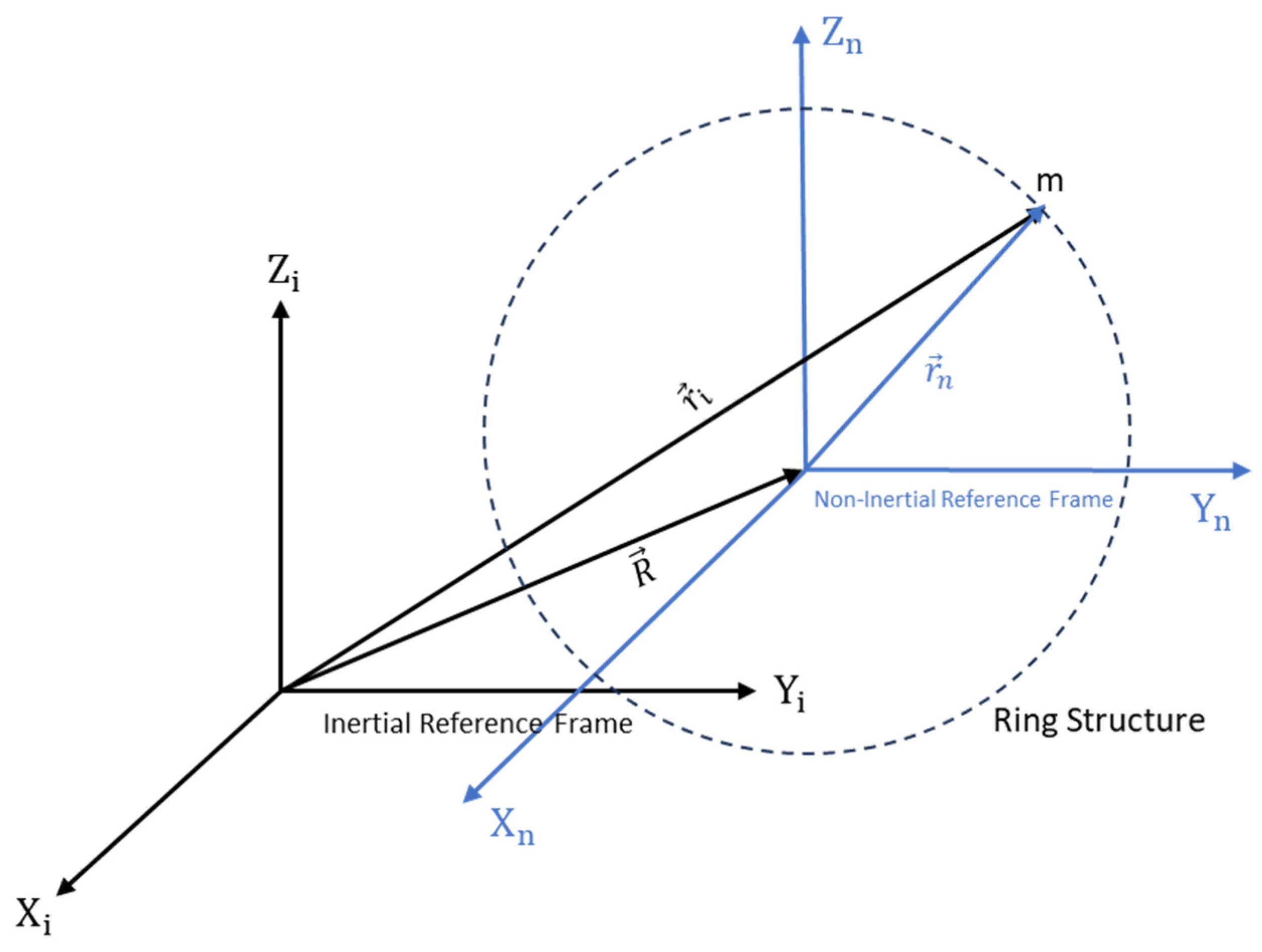
Figure 2.
A schematic view of Inertial and non-inertial reference frames with position vectors.
An observer from an inertial reference frame (stationary) can see a point mass "m" with a position vector and hence the force acting on the inertial reference frame is written below.
We start with the position vectors, then take the second derivative of the position vectors and the outcome arrangements are shown below.
ri = R+ rn
ri =R+rn
Now we substitute equation 3 into equation 1.
F=m(R+rn)
F−mR=mrn
The force is the inertial force observed from the non-inertial reference frame, is the force which is observed from the inertial reference frame and is the force from the non-inertial reference frame.
Now, we will consider a vector P that is interacting the relationship of the time derivative of the inertial reference frame with the time derivative of the non-inertial reference frame. The vector P will rotate with angular velocity in a non-inertial reference frame with respect to the inertial reference frame and is written as Equation 7.
Further, we will investigate the equation relating the velocities in the inertial and non-inertial reference frames. We are going to use equation 1.7, and hence we consider the position vector .
The next step is to investigate the equation that relates accelerations in inertial and no-inertial reference frames. For this, we will use equation 1.7 and we are going to set in equation 7.
As we recall equation 7, the velocity observed by the inertial reference frame is equal to the velocity and angular velocity experienced by the non-inertial reference frame, it is . We plug this equation in to the equation 8.
As we can see, acceleration experienced in the inertial reference frame is equal to acceleration in the non-inertial reference frame with Coriolis acceleration and centripetal acceleration.
Now, we will consider the non-inertial reference frame with the inertial reference frame. We apply a rotation into the non-inertial reference frame. The representation of this concept is shown in Figure 3.
Now, we can understand the concept of the dynamics of the gyroscope when we apply Newton's second law of motion equation on the above acceleration equation with the gyroscope's mass as written in equations 16 and 17.
Here is the applied force on the reference frame, is the acceleration experienced by the inertial reference frame, the combination of () is the acceleration observed by the non-inertial reference frame, is a linear acceleration observed in the non-inertial reference frame, is the acceleration in the non-inertial reference frame, and does the non-inertial reference frame experience the angular velocity. The expression is the centripetal acceleration and the expression is the Coriolis acceleration. The Coriolis acceleration is the main concept that transfers the rotational energy of the non-inertial reference frame for measuring the rotation rate with respect to the inertial reference frame.
2.2. Motion Equations of Vibrating Ring Gyroscope
The MEMS vibrating ring gyroscope is an inertial sensor that delivers precise and reliable angular rate measurements in dynamic motion environments. Utilizing Coriolis force and resonant frequency principles, this miniaturized device offers excellent sensitivity and stability, ideal for applications such as navigation, stabilization, and motion tracking. Dual-axis gyroscopes, which measure angular motion in two orthogonal axes, tend to be larger and consume more power than the MEMS vibrating ring gyroscope. The MEMS vibrating ring gyroscope outshines dual-axis and tuning fork gyroscopes in several key aspects, including size, power consumption, sensitivity, and reliability. Its advanced design and unique operating principles make it a highly attractive sensor for various applications, including navigation, stabilization, and motion tracking [17,18,19].
In this section, we present the development of a linear mechanical model for a vibrating ring resonator. The ring structure consists of eight semicircular support springs that are connected with the fixed anchor support [20,21,22,23,24]. The vibrational mode shapes characterise the oscillations of the ring. In the case of symmetric design structures, such as vibrating ring, it is seen that mode shapes appear in pairs, exhibiting identical natural frequencies and being oriented orthogonally to each other.
2.2.1. Coordinates for Vibrating Ring Gyroscope
A proposed MEMS vibrating internal ring resonator with eight semicircular beams connected to the externally placed anchors makes a complete vibrating ring gyroscope, as shown in Figure 4. In this study, we will consider inplane displacements of the vibrating ring and evaluate the elliptical vibrational modes. A vibrating ring gyroscope possesses a symmetric design structure, so the vibrational modes occur in identical pairs with the same resonance frequency.
Firstly, the vibrating ring is considered as a perfect round ring with thickness "t". The cross-sectional area of the ring is shown in Figure 5. Where "h" is height, R is the radius of the ring center line, "t" is the thickness of the ring, and "A" is the cross-sectional area of the ring. The ring's displacement and elastic deformation are relatively small, so we consider a linear model of the vibrating ring gyroscope.
We start the analysis with ring motion and consider the elliptical vibrational mode only, which is also represented by 2. The inplane vibrations of a vibrating ring are shown in Figure 6. Each infinitesimal element inplane vibration possesses two degrees of freedom. The displacements can be characterized in local polar coordinates using the variables. and . Under the assumption of inextensional displacement of the ring. The radial displacement and tangential displacement of the ring in relation to the mid-section of the ring at a specific ring angle can be expressed as equations 18 and 19.
2.2.2. Various Energies Effect
To understand the motion equations of the vibrating ring structure, we will evaluate the effects of various energies on the ring resonator and the main mode of vibration of the ring structure, considered as the coordinates of 2θ elliptical vibrations, as shown in Figure 6. We will use the Lagrange equation to determine the motion equation for the vibrating ring gyroscope. The given scheme of the energy equation is shown below. Here represents the Lagrange equation, which is ). Where is the kinetic energy, is the Rayleigh damping, is the strain energy and is the strain energy of the semicircular support beams.
- Kinetic Energy
To find the kinetic energy of the vibrating ring, we need to consider the displacements of the ring and the central anchor. The absolute displacements of the ring are denoted by and and for the central anchor, denoted as and . To determine the absolute displacements denoted as and of the vibrating ring system, we need to combine the displacements terms of the vibrating ring and centrally placed anchor. The absolute velocities and of the ring are given in equations 21 and 22.
Hence, the kinetic energy of the vibrating ring is written in equation (23)
Here is the density, is the radius, and is the cross-sectional area of the vibrating ring gyroscope. By putting equations 21 and 22 in equation 23 and further solving it, we find out the kinetic energy of the ring as equation 24 where represents the mass of the vibrating ring.
Equation 24 provides a detailed dynamic movement of the ring through the kinetic energy equation. The equation considered both the rigid body displacement of the ring and the elliptical mode of the ring structure, which pertain to the displacements with inplane of the motion of the ring. Moreover, the equation considers the influence of base excitation, which refers to external forces applied on the anchors that the ring is connected to. One important feature is the decoupling of the generalized coordinates and that represent the motion of the ring. The coordinates, represented as in the equation, are not mutually dependent in calculating kinetic energy. The phenomenon of uncoupling suggests that the various components of motion, such as inplane vibrations and base excitation, contribute to the overall kinetic energy of the vibrating ring gyroscope system.
- Elastic Strain Energy
In relation to the concept of the elastic strain energy, it is supposed that the vibrating ring possesses elastic properties and corresponds to Hook's law. The law states that stress is directly proportional to strain, with constant proportionality being Young's Modulus "E" for the material. Hence the elastic strain energy "" is.
Where is the radius of the ring and is the normal strain of the ring. The normal strain of the ring can be calculated as.
The term "" refers to the distance of a point of the ring from the central axis. As mentioned, the inextensionality of the ring, which makes at . Therefore, equation 27 becomes simpler and shows the extensional strain of the ring.
We have the elastic strain energy equation by putting Equations 26 and 27 into equation 25.
The elastic strain energy equation shows the elliptical modes of the ring and also shows that the generalized ring coordinates are not connected in the strain energy equation.
- Strain Energy of Semicircular beams
The flexible beams are the integral parts of any MEMS vibrating gyroscope system. The semicircular beams are the supporting structure to the vibrating ring in the vibrating ring gyroscope system. In Figure 4, the eight semicircular beams are connected to support the ring structure. As we can see, the semicircular beams are relatively small to the ring structure, so we can neglect the mass of the semicircular beams. In this scenario, the kinetic energy of the semicircular beam could be considered zero.
When the force is applied to the vibrating structure, the semicircular beams undergo radial and tangential direction. We will consider semicircular beam radial and tangential stiffness separately, as described in Figure 7 [25].
The strain energy equation can determine the stiffness constant for a semicircular beam when subjected to an applied force or an external rotation, which results in tangential and radial displacements, respectively. Therefore further, we will determine tangential and radial stiffness constant.
The tangential strain energy equation for tangential displacement is presented as equation 30. Where is Young's modulus, is the moment of inertia, is the bending moment experienced, and is the differential width of the semicircular beam.
The above equation is further solved [25] and presented below.
Where is the net applied force, is the radius of the semicircular support beam, and is the imaginary moment experienced by the semicircular support beam when subjected to the force. Further solving the tangential strain energy equation determines the tangential stiffness constant.
The radial strain energy equation for radial displacement is presented as equation 33.
The above equation further solved and determined the radial stiffness constant which is shown in equation 34, where is the length of the beam.
The complete stiffness constant equation for the semicircular support beam can be written as.
There are eight semicircular support beams are attached to the vibrating ring. Therefore, the total strain energy for semicircular beams could be written as equation 36. Where ith represents the semicircular support beam position attached to the ring.
By putting equations 18 and 20 into equation 36, we can further determine the total strain energy for eight semicircular beams attached to the vibrating ring.
- Damping Energy
The damping energy for MEMS inertial sensors in the vacuum is the thermoelastic damping [3,26]. The energy dissipation factor is considered as Rayleigh damping function. The Rayleigh damping function for the MEMS vibrating ring gyroscope system [27] can be expressed as.
The given expressions and are elliptical mode shape which is generally represented by 2.
To derive the equations of motion for the vibrating internal ring gyroscope, we will be using Lagrange's equation, and which is given as equation 20.
The vibrating internal ring gyroscope resonator mechanical model is shown in Figure 4. The derived energy equations will be put into equation 20 to find the motion equation of a vibrating ring gyroscope.
To simplify the equations of motion, we consider , , and .
The natural frequency of the gyroscope and the Quality factor of the gyroscope . Therefore, the refined equations of motion for the vibrating ring gyroscope are presented below.
2.3. Implication of Resonance Analysis on MEMS Vibrating Ring Gyroscope Design
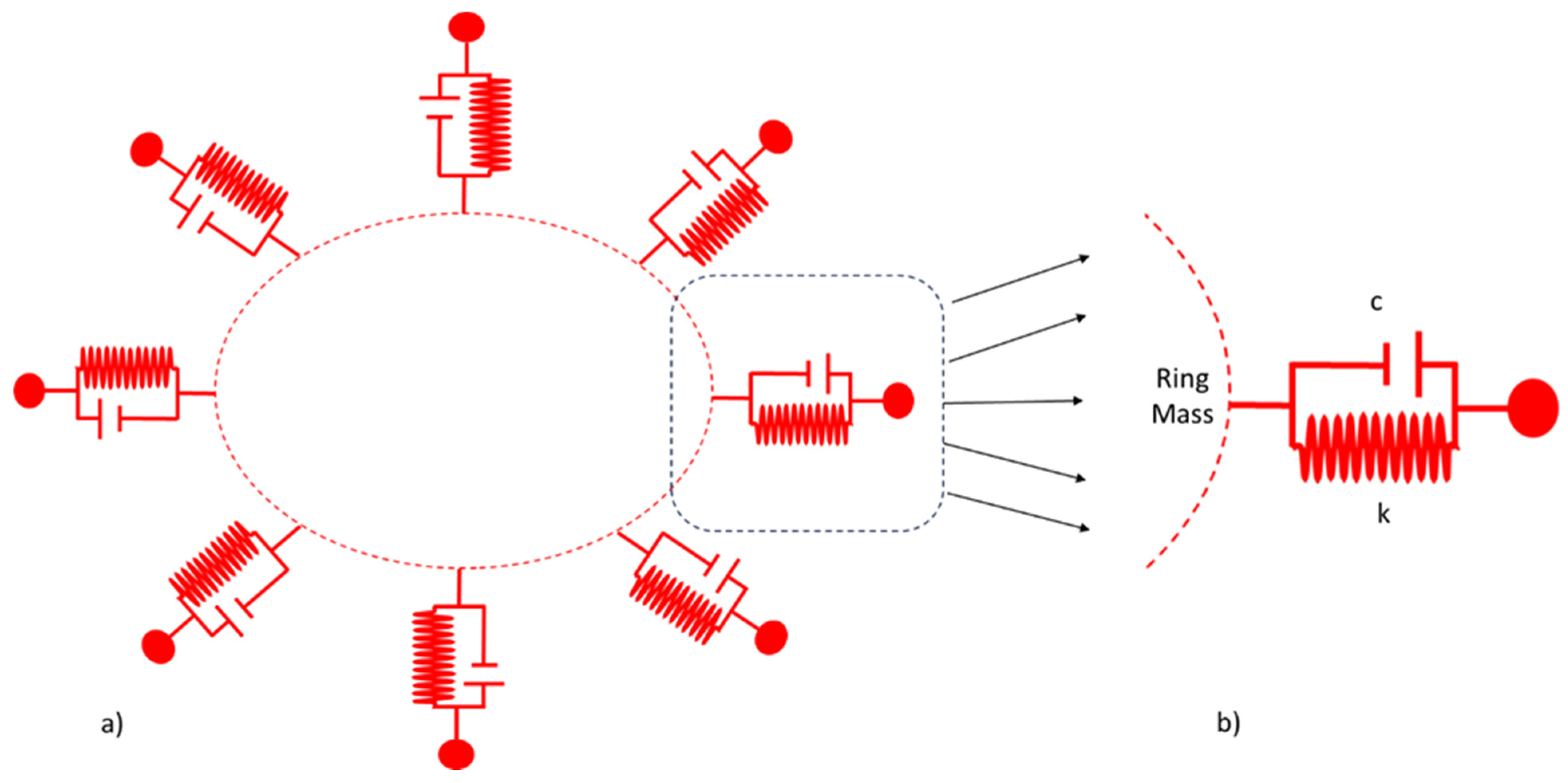
In this section, we will consider the elliptical mode of vibration for MEMS vibrating ring gyroscope. The spring-mass system for MEMs vibrating internal ring gyroscope is shown in Figure 8. The gyroscope system is comprised of the internal vibrating ring mass, spring damper, and externally supported anchors. There are eight support beams attached with the internal vibrating ring mass and the whole vibrating structure system is connected to the externally supported anchors.
During the driving operation, the MEMS vibrating ring gyroscope comprised of a single degree of freedom resonator. Therefore, to understand the MEMS vibrating ring gyroscope dynamics, we consider the 1/8th portion of the ring gyroscope as shown in Figure 9b. The considered portion comprised a single resonator of one degree of freedom with one support beam and damping connected to the external anchor. The same concept applies to sensing purposes as the vibrating ring gyroscope comprised of the symmetric design.
Let us consider the Figure 11b; we have a single resonator with one degree of freedom. As previously derived, the equation (26) is implemented on the 1/8th portion of the vibrating ring gyroscope.
In further elaboration, the natural frequency is a parameter that analyses the oscillation behavior of the vibrating structure without damping. The damping factor measures the damping present in the vibrating system relative to the critical damping. The equation of the motion for the considered portion becomes.
The Laplace transform function for the single degree of freedom can be written to simplify the equation.
When a vibrating ring resonator is subjected to the harmonic force at the given frequency . The system responds with a steady-state harmonic excitation, which can be expressed as
Here is the response amplitude and can determined as
Here is the amplitude of the applied force, is the frequency of the applied force, is the natural frequency of the vibrating ring, and is the phase angle between the applied force and the response.
Now consider the vibrating ring gyroscope as two degrees of freedom resonator. This means we consider driving and sensing axes. As discussed earlier, the equations of motion for the vibrating ring gyroscope are shown below. The vibrating ring gyroscope oscillates in one direction when there is no rotation on to the device.
In this situation, no external force is applied to the ring gyroscope's secondary motion. Therefore, we can write a primary response and secondary response of the gyroscope after the closed form solution as below.
The phase shift due to the primary oscillation motion can be determined as.
After natural oscillations are damped, the equation of solutions 53 and 55 reveals that the frame of the sensitive element, in conjunction with the proof mass, performs forced oscillations along the driving axis with an amplitude corresponding to the excitation force. During this time, the proof mass will not shift along the driving axis, and therefore, the sensing output will be at zero.
Previously, we considered that there is no rotation when the vibrating ring gyroscope oscillates only in the driving axis, which means the oscillation will remain absent in the sensing axis. Now, we will study the behavior of the vibrating ring gyroscope when it rotates with a constant angular rate, and we will see cross-couplings and occur in both the axes. Here, we have effective accelerations and due to the external forces.
In this situation, we have equations in which we have cross couplings when the rotation applies to the vibrating ring gyroscope. If there are no forces affecting the oscillations in the sensing axis then the and we will assume there is no coupling between both driving and sensing axes. Hence, sensing oscillation will only work on the angular rate.
The solutions of equations 56 and 57 are of interest due to their role in measuring angular rate, while the natural solution pertains to transient phenomena. If the excitation of the driving oscillation follows a harmonic pattern, the acceleration resulting from the excitation forces can be mathematically expressed as.
Here is the effective acceleration, is the amplitude of the effective acceleration, is the excitation frequency, and is the phase constant. We will write the solution for the driving and sensing oscillations with respect to the decoupling the frame.
The complex amplitudes are deriving the forced oscillation at the given frequency and .
Now, we have constant amplitudes , and phases , for diving and sensing oscillations. We will substitute the above solutions in equations 56 and 57.
To determine the solutions of the complex amplitudes are given below.
The phases and of the driving and sensing oscillations, which correspond to the angles of and , can be determined by the given equations.
2.4. Mode Matching in Vibrating Ring Gyroscopes
The vibrating ring gyroscope operates on two primary modes of oscillations, driving oscillations, where the ring continuously vibrates in two orthogonal axes like an elliptical ring. The second vibration mode is sensing oscillations when the device experiences rotation, where the vibrating ring gyroscope oscillates at 45 degrees between two orthogonal axes and maintains the same elliptical vibration mode [28,29,30,31,32].
In an ideal situation, the driving and sensing resonance frequencies should be matched. This mode matching amplifies the sensing mode response to the angular rate input, making the gyroscope performance more accurate and precise. We consider a case where the vibrating ring gyroscope sensing frequency is of 10 kHz and has a quality factor is 1000. At perfect mode matching, the amplification factor of the response is 1000, which is the same as the quality factor. The scenario is shown in Figure 12. A vibrating ring gyroscope operates at or close to its resonant frequency and is more susceptible to any fluctuations in the system that shift the resonance frequency. As shown in Figure 10, a 5Hz deviation can cause a significant 29 % loss in the amplification factor. A 10 Hz shift increases to a 55 % loss in the amplification factor.
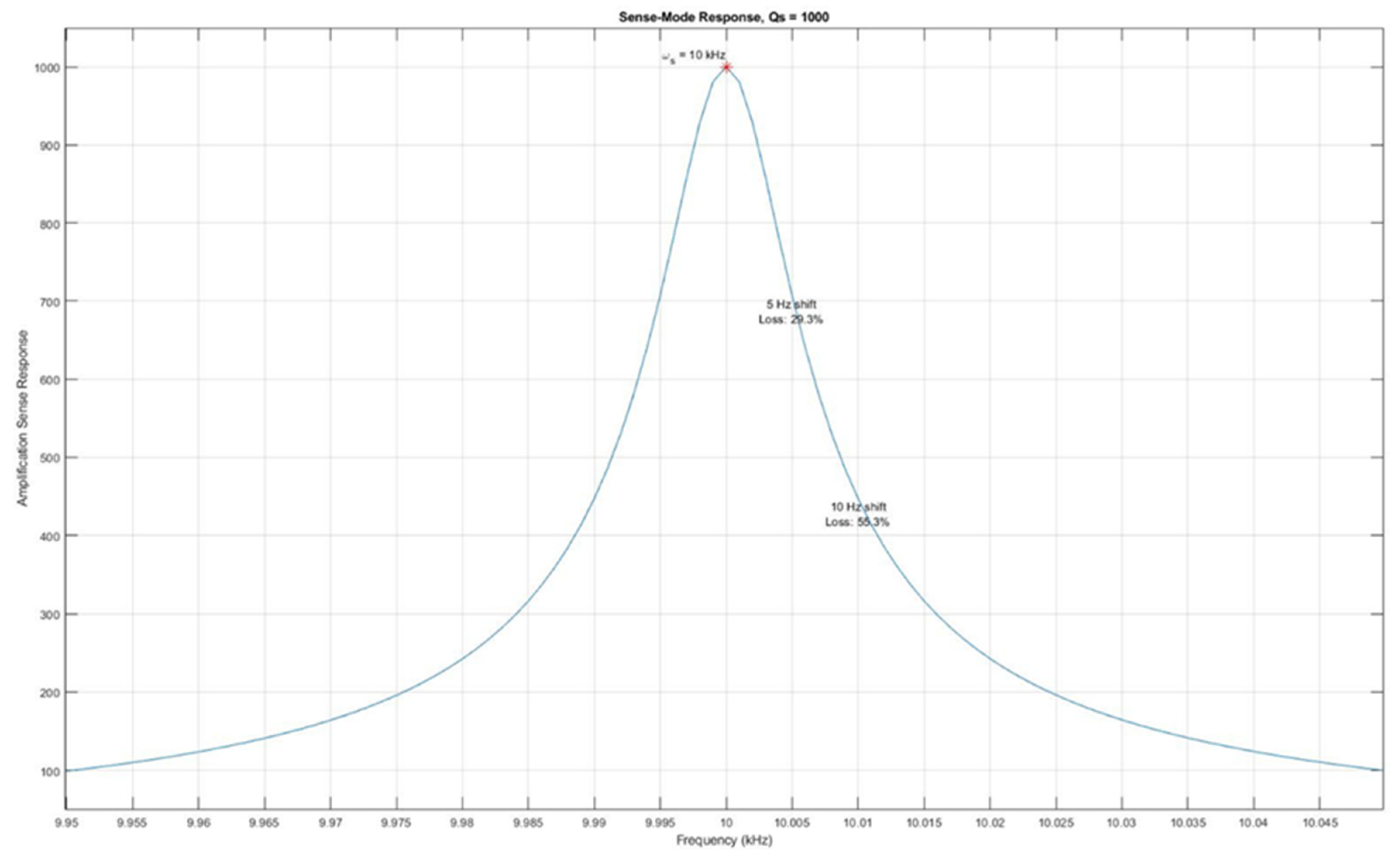
Figure 10.
The effect of a resonance frequency shift on the sense mode amplification.
In another scenario, if the quality factor increased to 10000, which gives us a higher amplification factor, it means better results. This also narrows down the operational bandwidth. In this case, if the frequency just shifts 5Hz, it will decrease the gain to 90%, as seen in Figure 11.
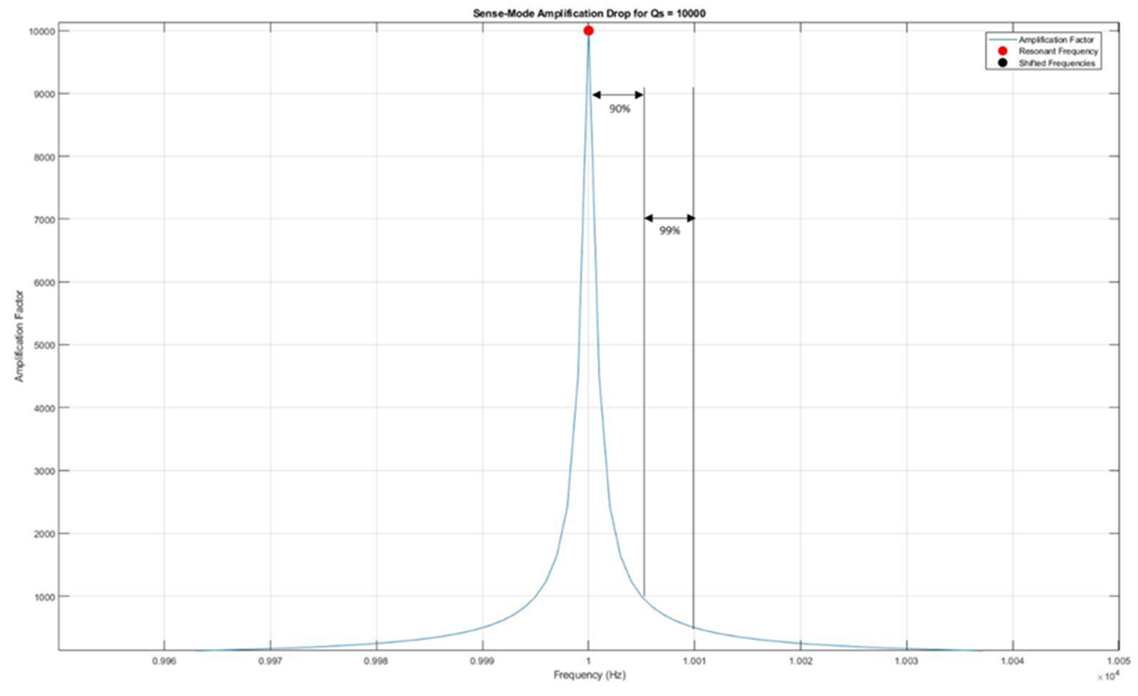
Figure 11.
A high-quality factor gyroscope is more susceptible to high loss of gain.
As discussed earlier, operating mode-matched resonance frequencies is quite challenging due to many factors, like unwanted vibrations, microfabrication tolerances, and environmental factors. Therefore, operating the sensing frequency with low peaks is better as it will not impact the sensing amplification factor much. By doing this, the sensing resonance frequency is deliberately offset with a small percentage of the driving frequency. This intentional gap between the driving and sensing resonance frequencies is typically known as a frequency separation system.
Most MEMS vibrating gyroscopes work on the principle of translational motion of single-proof mass system. Translational motion provides better gyroscopic performance and simple microfabrication processes because of single-proof mass system. Some of the gyroscopes utilize the rotational motion of the spring-mass system but add some complex operational processes. On the other hand, dual mass-spring system gyroscopes require more complex microfabrication processes, which sometimes contribute to unwanted errors in the gyroscope operations.
3. Conclusions
The thorough investigation of the inplane vibrational dynamics of the MEMS internal vibrating ring gyroscope with semicircular beams is fully presented as an analytical model of the vibrating ring gyroscope. This includes elliptical vibrational modes assuming inextensional displacements, resulting in detailed equations that could effectively demonstrate a vibrating ring resonator's radial and tangential displacement. The symmetric design structure of the vibrating ring gyroscope provides identical pairs of elliptical vibrational modes. The importance of mode matching on the performance of the gyroscope and disadvantage when sensing frequency has the same peak value as the driving frequency. The derived equations are crucial in order to optimize the design of the vibrating ring gyroscope for increased performance and sensitivity.
Author Contributions
The conceptual framework of the MEMS vibrating ring gyroscope was given by K. McKee and I. Howard. The detailed design process, analytical findings, and preparation of the figures were carried out by W. A. Gill. Additionally, W. A. Gill took the lead in writing and reviewing the manuscript, ensuring the final draft was refined and ready for publication. Supervisory guidance was provided by I. Howard, I. Mazhar, and K. McKee.
Funding
The research support is funded by the Australian government's research training program (RTP) through Curtin University.
Data Availability Statement
Not Applicable.
Conflicts of Interest
The authors declare no conflict of interest.
References
- Jia J, Ding X, Qin Z, Ruan Z, Li W, Liu X, et al. Overview and analysis of MEMS Coriolis vibratory ring gyroscope. Measurement. 2021;182:109704. [CrossRef]
- Wu X, Xi X, Wu Y, Xiao D. Cylindrical Vibratory Gyroscope: Springer; 2021. [CrossRef]
- Acar C, Shkel A. MEMS vibratory gyroscopes: structural approaches to improve robustness: Springer Science & Business Media; 2008. [CrossRef]
- Apostolyuk V. Theory and design of micromechanical vibratory gyroscopes. MEMS/NEMS: Handbook Techniques and Applications: Springer; 2006. p. 173-95. [CrossRef]
- Li Z, Gao S, Jin L, Liu H, Niu S. Micromachined vibrating ring gyroscope architecture with high-linearity, low quadrature error and improved mode ordering. Sensors. 2020;20(15):4327. [CrossRef]
- Kou Z, Cui X, Cao H, Li B, editors. Analysis and Study of a MEMS Vibrating Ring Gyroscope with High Sensitivity. 2020 IEEE 5th Information Technology and Mechatronics Engineering Conference (ITOEC); 2020. Chongqing, China: IEEE.
- Syed WU, An BH, Gill WA, Saeed N, Al-Shaibah M, Al Dahmani S, et al. Sensor Design Migration: The Case of a VRG. IEEE Sensors J. 2019;19(22):10336-46. [CrossRef]
- Xia D, Yu C, Kong L. The development of micromachined gyroscope structure and circuitry technology. Sensors. 2014;14(1):1394-473. [CrossRef]
- Passaro VMN, Cuccovillo A, Vaiani L, De Carlo M, Campanella CE. Gyroscope Technology and Applications: A Review in the Industrial Perspective. Sensors. 2017;17(10):2284. [CrossRef]
- Lee JS, An BH, Mansouri M, Yassi HA, Taha I, Gill WA, et al. MEMS vibrating wheel on gimbal gyroscope with high scale factor. Microsyst Technol. 2019;25:4645-50. [CrossRef]
- Liang F, Liang D-D, Qian Y-J. Dynamical analysis of an improved MEMS ring gyroscope encircled by piezoelectric film. International Journal of Mechanical Sciences. 2020;187:105915. [CrossRef]
- Gill WA, Howard I, Mazhar I, McKee K. A Review of MEMS Vibrating Gyroscopes and Their Reliability Issues in Harsh Environments. Sensors. 2022;22(19):7405. [CrossRef]
- Liang F, Liang D-D, Qian Y-J. Nonlinear Performance of MEMS Vibratory Ring Gyroscope. Acta Mechanica Solida Sinica. 2021;34(1):65-78. [CrossRef]
- Gill WA, Ali D, An BH, Syed WU, Saeed N, Al-shaibah M, et al. MEMS multi-vibrating ring gyroscope for space applications. Microsyst Technol. 2020;26:2527-33. [CrossRef]
- Cao H, Liu Y, Kou Z, Zhang Y, Shao X, Gao J, et al. Design, fabrication and experiment of double U-beam MEMS vibration ring gyroscope. Micromachines. 2019;10(3):186. [CrossRef]
- Kou Z, Liu J, Cao H, Shi Y, Ren J, Zhang Y. A novel MEMS S-springs vibrating ring gyroscope with atmosphere package. AIP Advances. 2017;7(12). [CrossRef]
- Yoon SW, Lee S, Najafi K. Vibration sensitivity analysis of MEMS vibratory ring gyroscopes. Sensors and Actuators A: Physical. 2011;171(2):163-77. [CrossRef]
- Kou Z, Liu J, Cao H, Han Z, Sun Y, Shi Y, et al. Investigation, modeling, and experiment of an MEMS S-springs vibrating ring gyroscope. Journal of Micro/Nanolithography, MEMS, and MOEMS. 2018;17(1):015001-. [CrossRef]
- Ayazi F, Najafi K, editors. Design and fabrication of high-performance polysilicon vibrating ring gyroscope. Proceedings MEMS 98 IEEE Eleventh Annual International Workshop on Micro Electro Mechanical Systems An Investigation of Micro Structures, Sensors, Actuators, Machines and Systems (Cat No 98CH36176; 1998: IEEE.
- Ayazi F, Hsiao H, Kocer F, He G, Najafi K, editors. A High Aspect-Ratio Polysilicon Vibrating Ring Gyroscope. Solid-State Sensor and Actuator Workshop; 2000. Hilton Head Island, South Carolina: IEEE.
- Shkel AM, Horowitz R, Seshia AA, Park S, Howe RT, editors. Dynamics and control of micromachined gyroscopes. Proceedings of the 1999 American Control Conference (Cat No 99CH36251); 1999: IEEE.
- He G, Najafi K, editors. A single-crystal silicon vibrating ring gyroscope. Technical Digest MEMS 2002 IEEE International Conference Fifteenth IEEE International Conference on Micro Electro Mechanical Systems (Cat No 02CH37266); 2002: IEEE.
- Gallacher BJ, Hedley J, Burdess JS, Harris AJ, Rickard A, King DO. Electrostatic correction of structural imperfections present in a microring gyroscope. J Microelectromech Syst. 2005;14(2):221-34. [CrossRef]
- Liu K, Zhang W, Chen W, Li K, Dai F, Cui F, et al. The development of micro-gyroscope technology. Journal of Micromechanics and Microengineering. 2009;19(11):113001. [CrossRef]
- Gill WA, Howard I, Mazhar I, McKee K. Design and Considerations: Microelectromechanical System (MEMS) Vibrating Ring Resonator Gyroscopes. Designs. 2023;7(5):106. [CrossRef]
- Duwel A, Gorman J, Weinstein M, Borenstein J, Ward P. Experimental study of thermoelastic damping in MEMS gyros. Sensors and Actuators A: Physical. 2003;103(1-2):70-5. [CrossRef]
- Wong S, Fox C, McWilliam S. Thermoelastic damping of the in-plane vibration of thin silicon rings. Journal of Sound and Vibration. 2006;293(1-2):266-85. [CrossRef]
- Tsai D-H, Fang W. Design and simulation of a dual-axis sensing decoupled vibratory wheel gyroscope. Sensors and Actuators A: Physical. 2006;126(1):33-40. [CrossRef]
- Hyun An B, Gill WA, Lee JS, Han S, Chang HK, Chatterjee AN, et al. Micro-Electromechanical Vibrating Ring Gyroscope with Structural Mode-Matching in (100) Silicon. sens lett. 2018;16(7):548-51. [CrossRef]
- Zou X, Zhao C, Seshia AA, editors. Edge-anchored mode-matched micromachined gyroscopic disk resonator. 2017 19th International Conference on Solid-State Sensors, Actuators and Microsystems (TRANSDUCERS); 2017: IEEE.
- Ahn CH, Ng EJ, Hong VA, Yang Y, Lee BJ, Flader I, et al. Mode-matching of wineglass mode disk resonator gyroscope in (100) single crystal silicon. 2014;24(2):343-50. [CrossRef]
- Fan B, Guo S, Cheng M, Yu L, Zhou M, Hu W, et al. Frequency symmetry comparison of cobweb-like disk resonator gyroscope with ring-like disk resonator gyroscope. IEEE Electron Device Letters. 2019;40(9):1515-8. [CrossRef]
Figure 1.
The dynamic illustration of the primary oscillation of the Vibrating ring gyroscope.
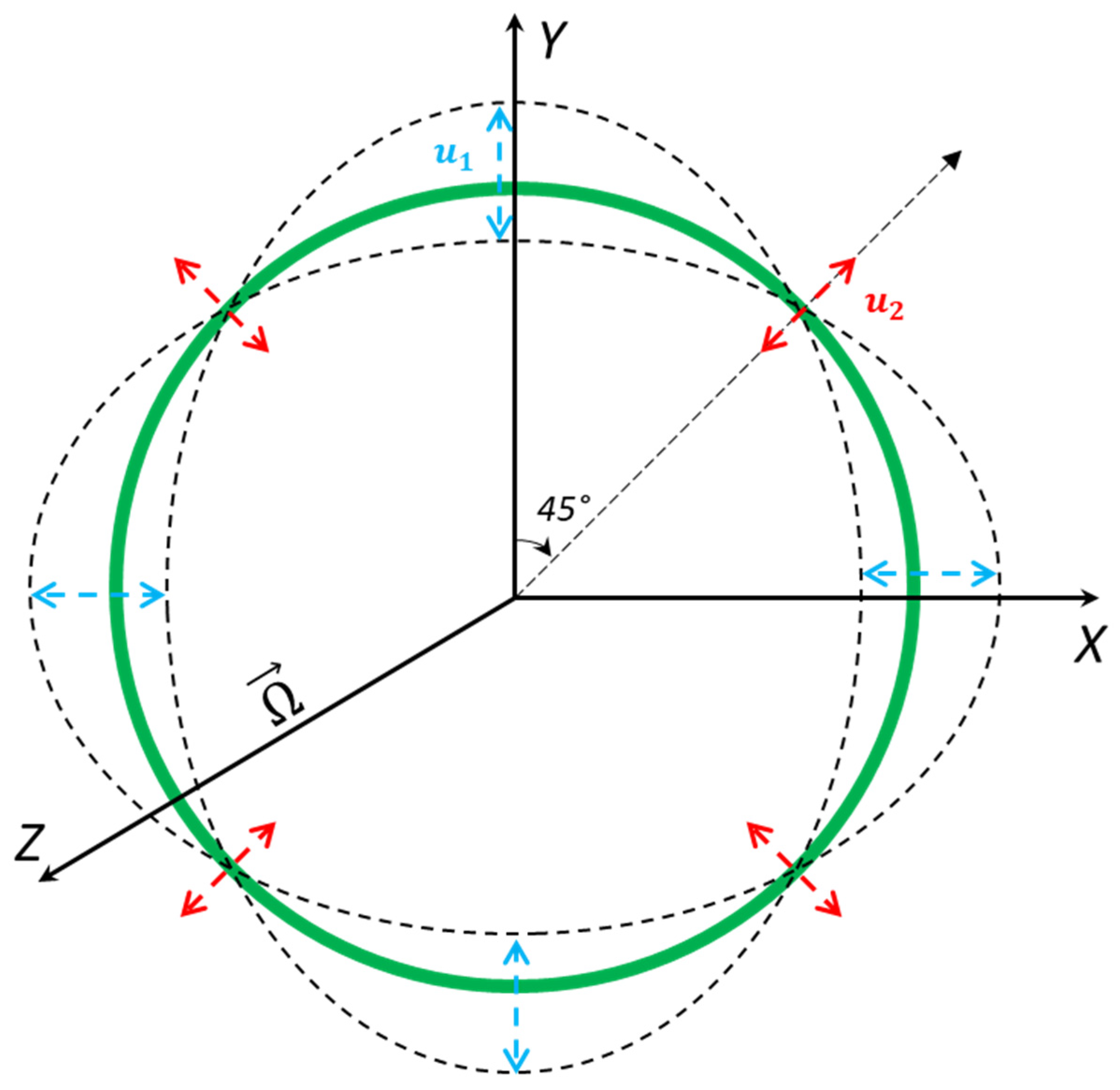
Figure 3.
A schematic view of the position vector of a non-inertial reference frame with respect to an inertial reference frame with rotation applied.
Figure 3.
A schematic view of the position vector of a non-inertial reference frame with respect to an inertial reference frame with rotation applied.
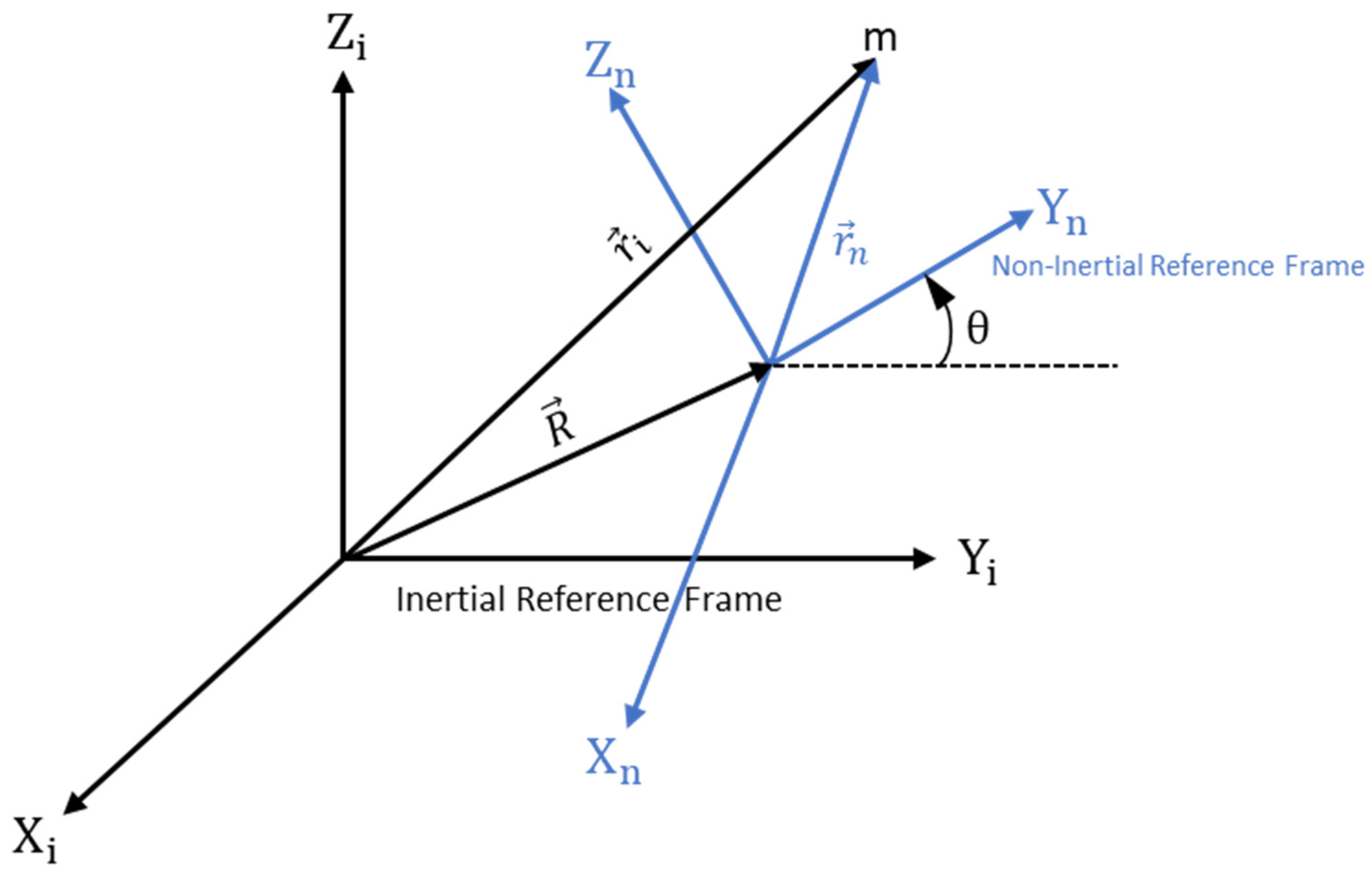
Figure 4.
A schematic view of the internal vibrating ring gyroscope.
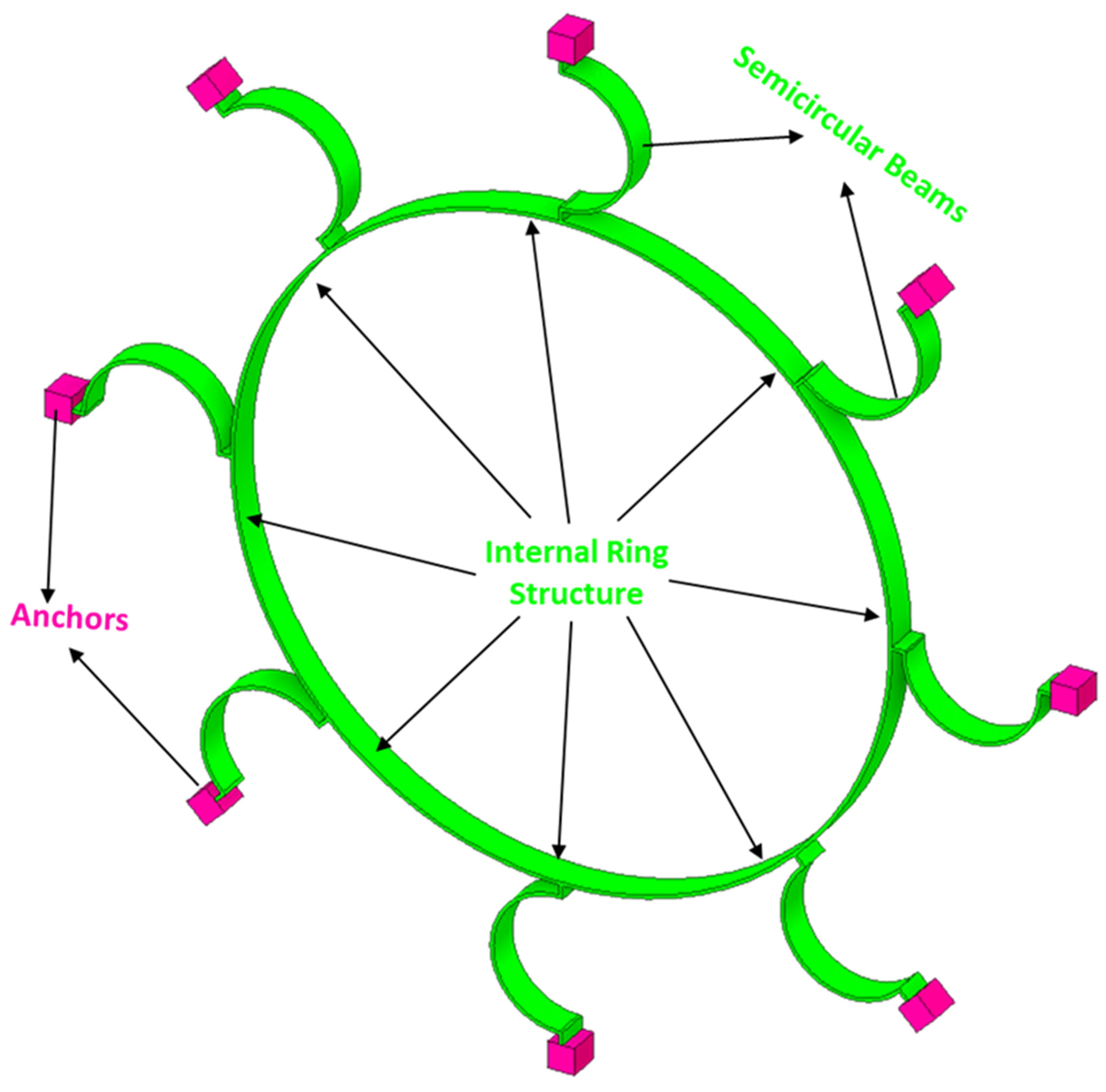
Figure 5.
A cross-sectional area "A" of the ring structure with the centreline radius "R", height "h", and thickness "t".
Figure 5.
A cross-sectional area "A" of the ring structure with the centreline radius "R", height "h", and thickness "t".

Figure 6.
The displacement of the inplane ring as an elliptical mode of vibration.
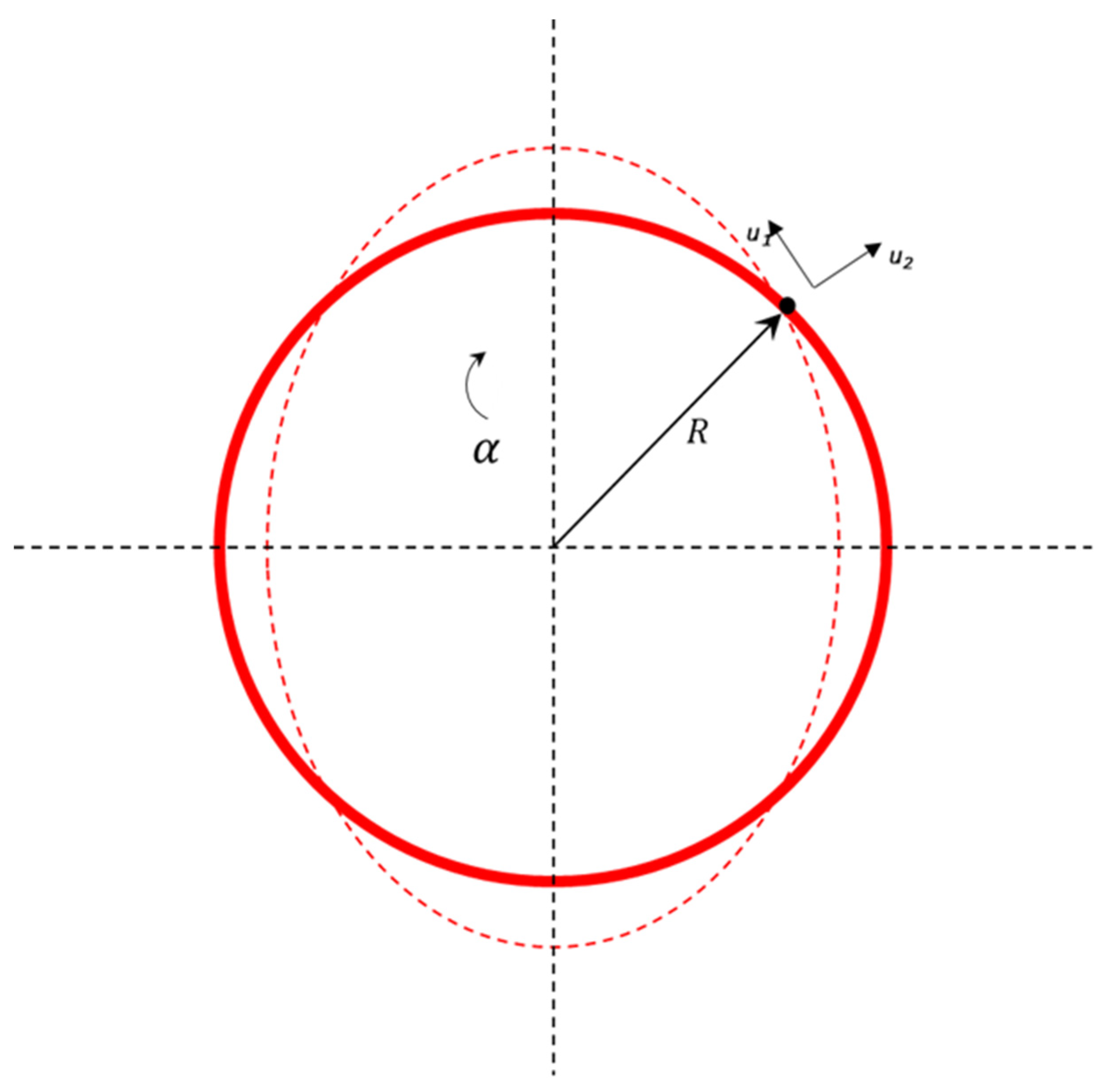
Figure 7.
The semicircular support stiffness depiction model (a) complete (b)tangential (c) radial.
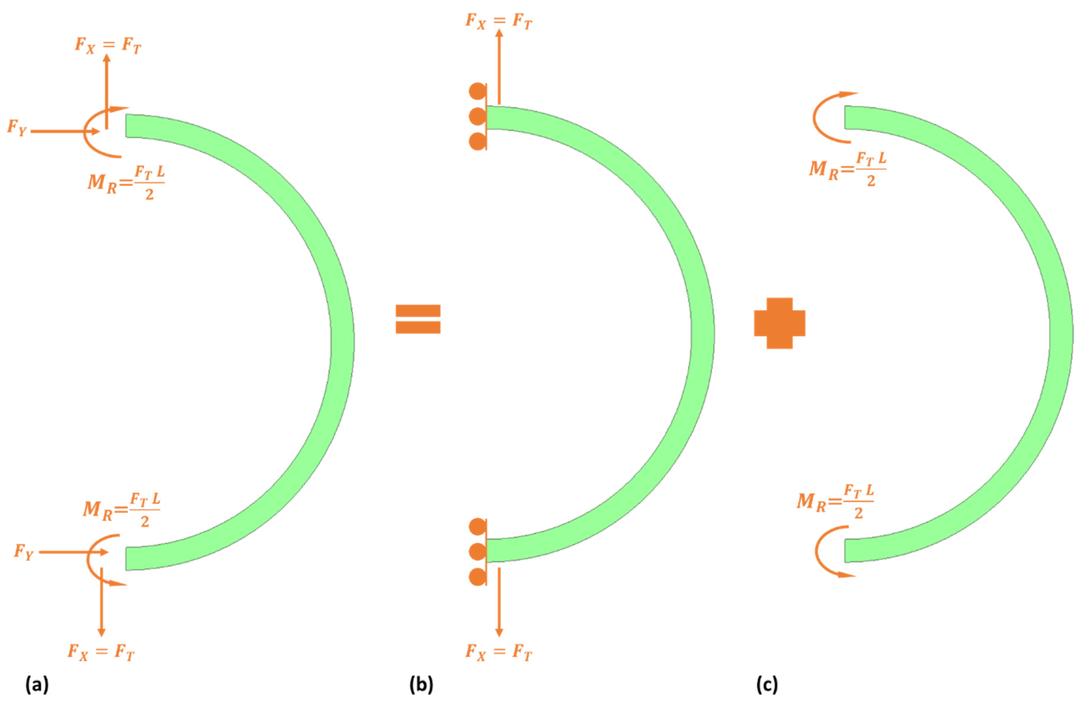
Figure 8.
A spring mass damping system for MEMS vibrating ring gyroscope.
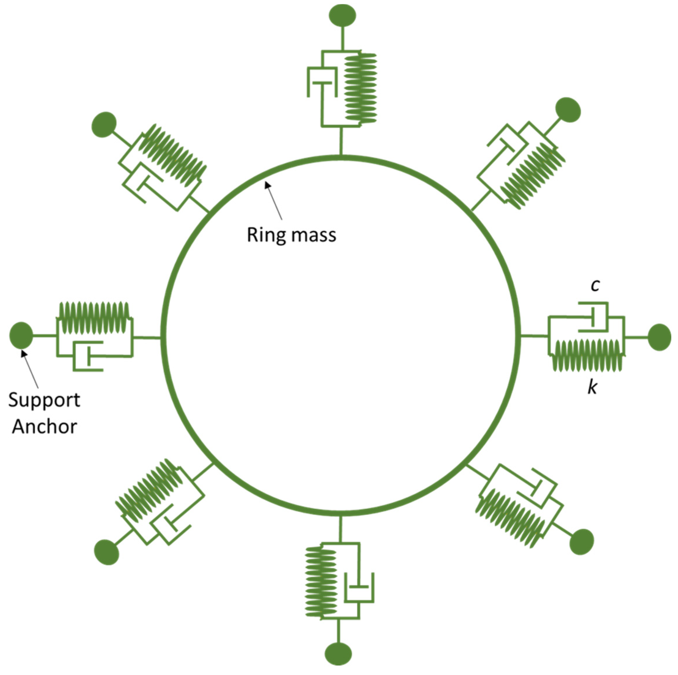
Figure 9.
Driving mode of a spring mass system for vibrating ring gyroscope. (a) Complete architecture (b) Single ring resonator.
Figure 9.
Driving mode of a spring mass system for vibrating ring gyroscope. (a) Complete architecture (b) Single ring resonator.
Disclaimer/Publisher’s Note: The statements, opinions and data contained in all publications are solely those of the individual author(s) and contributor(s) and not of MDPI and/or the editor(s). MDPI and/or the editor(s) disclaim responsibility for any injury to people or property resulting from any ideas, methods, instructions or products referred to in the content. |
© 2023 by the authors. Licensee MDPI, Basel, Switzerland. This article is an open access article distributed under the terms and conditions of the Creative Commons Attribution (CC BY) license (http://creativecommons.org/licenses/by/4.0/).
Copyright: This open access article is published under a Creative Commons CC BY 4.0 license, which permit the free download, distribution, and reuse, provided that the author and preprint are cited in any reuse.


