Submitted:
27 October 2023
Posted:
27 October 2023
You are already at the latest version
Abstract
During the hand-eye calibration process of the manipulator, the Euclidean distance error of the calibration results cannot be calculated because the true values of the hand-eye conversion matrix cannot be obtained. In this paper, a new method of projection error analysis is presented. Error analysis is carried out by using a priori knowledge that the location of AR markers is fixed in the calibration process. The coordinates of the AR marker center point are reprojected to the pixel coordinate system, and then compared with the true pixel coordinates of the AR marker center point obtained by corner detection or manual labeling in order to obtain the Euclidean distance between the two coordinates as the basis for error analysis. Experimental results show that the proposed optimization method can greatly improve the accuracy of hand-eye calibration results.
Keywords:
hand-eye calibration
; reprojection error analysis
; manipulator object grasping
1. Introduction
Robotic grasping is a crucial function of robots, and it involves identifying and locating the target object through a visual sensor. To ensure the accuracy of the visual information and achieve coordinated hand-eye motion, it is essential to analyze the manipulator's hand-eye visual calibration problem and improve its accuracy. Hand-eye calibration establishes the transformation matrix between the camera's pixel coordinate system and the manipulator's spatial coordinate system. By transforming pixel coordinates into the manipulator's coordinate system, the robot can calculate the necessary motor movements to reach the target position and control the manipulator. Hand-eye calibration can be divided into eye-to-hand and eye-in-hand, depending on the camera's installation position. This paper focuses on experiments using the eye-in-hand installation.
Traditional calibration methods build calibration models based on pre-set imaging scenes, and select optimal algorithms, including reference-based, active vision and self-calibration methods, to calculate camera parameters based on scene geometric constraints. Based on the reference object camera calibration method, the corner points of the target image are extracted as control points, a system of equations corresponding to the pixels and spatial coordinates is constructed, and then the optimization algorithm is used to calculate the parameters, in which the shape and size of the reference object and other information are known. The reference object is divided into one-dimensional straight line [1], two-dimensional plane calibration plate, three-dimensional solid block, etc. according to the spatial dimension. Due to its simple production and controllable accuracy, flat calibration plates are often used as targets in industrial applications instead of calibration blocks. Commonly used calibration plate patterns include checkerboards, solid circles [2], concentric rings, etc. In recent years, various new templates have been proposed [3]. The Zhang Zhengyou calibration method [4] based on the chessboard calibration board is a classic representative of this type of method. This method has strong imaging constraints, simple calibration process, and high algorithm robustness. This type of method has strong imaging constraints, simple calibration process, and high algorithm robustness, but the production and maintenance cost of high-precision reference objects is high, and it is lost in situations where it is impossible to carry reference objects significance. The camera calibration method based on active vision obtains multiple images by accurately controlling special movements such as pure rotation and translation of the camera or target, and uses controllable quantitative motion constraints to determine the internal and external information of the camera. It is an important branch of self calibration methods. Typical methods include calibration based on pure rotational motion [5], calibration based on three orthogonal translation motions, calibration based on plane orthogonal motion, and calibration based on infinite plane homography matrix, hand eye calibration [6], self calibration method based on projection reconstruction, etc. Active visual calibration technology can linearly solve camera internal parameters, with strong algorithm robustness. However, strict requirements for control equipment limit its use and promotion. The camera self-calibration method does not need to set up a reference object or control the precise movement of the camera. It only uses the geometric consistency constraints of corresponding points in multiple frames of images [7,8] to solve the camera basic matrix, and does not rely on scene structure and motion information, including directly solving the Kruppa equation, methods based on absolute quadratic curves and absolute quadric surfaces [9,10], Pollefeys module constrained calibration [11,12], and hierarchical stepwise calibration methods under variable internal parameters [13] etc.
The focus of this paper is the hand-eye calibration algorithm. Since 1989, first proposed the problem of hand-eye calibration, domestic and foreign scholars have done a lot of research, such as Chen et al. proposed a noise-tolerant algorithm for robot sensor calibration using a planar disk in any three-dimensional direction [14], Li et al. proposed a hand-eye calibration method for linear laser sensors based on three-dimensional reconstruction [15] and Zhang et al. proposed a calibration method of hand-eye system with rotation and translation coupling [16]. The solution of the hand-eye calibration problems can be divided into two categories according to the solution order of the calibration matrix. One is to solve the rotation part and translation vector of the matrix at the same time. A typical algorithm is Andreff 's closed-loop solution of hand-eye calibration equation based on matrix direct product for calibration of small-scale moving measurement scenarios [17]; Tabb proposed a hand-eye calibration algorithm based on an iterative optimization method and solved it with a nonlinear optimizer [18]; Jiang et al. proposed a method to calibrate the hand-eye of EOD robot by solving the AXB = YCZD problem [19]. The other is to solve the rotation matrix of the calibration matrix first and then the translation vector of the calibration matrix. The most common one is the method proposed by Tsai and Lenz [20], which introduces the rotation axis-rotation angle system to describe the rotation motion; Liu et al. proposed a hand-eye calibration method for robot vision measurement system [21]; Zou et al. performed hand eye calibration on arc welding robots and laser vision sensors through semi definite programming [22]; Deng et al. proposed a hand-eye calibration method based on monocular robot [23]; But in fact, the above algorithm still has some space for optimization.
In the hand-eye calibration process of the real manipulator, the actual error of the calibration result cannot be calculated because the true value of the hand-eye transformation matrix cannot be obtained. A new error analysis method is needed. Therefore, a reprojection error analysis method is proposed. The contribution of this paper is to find that the only source of error in the process of hand-eye calibration in the simulation environment is the position and attitude calculation error of the AR marker. However, when using common algorithms for calibration, it is considered that the calculated pose is error-free, resulting in a certain error in the calibration results of each algorithm. The method of this paper innovatively utilizes the prior knowledge that the position marked by AR is fixed in the calibration process to conduct error analysis. First, the coordinates of the center point of the AR mark are re-projected to the pixel coordinate system, and then compared with the real pixel coordinates of the center point of the AR mark obtained by corner detection or manual labeling in order to obtain the Euclidean distance between the two coordinates, which is the basis for error analysis.
2. Coordinate systems definitions and hand-eye calibration equation
2.1. Coordinate systems definitions
In this paper, the camera is installed in an eye-in-hand manner in the robotic arm visual grasping system. The origin of the base coordinate system of the robotic arm, the end coordinate system of the robotic arm, the camera coordinate system, and the AR marker coordinate system are defined as 、、、, respectively. The coordinate system and its conversion relationship in the hand-eye calibration process are shown in Figure 1.
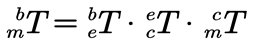
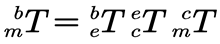
Let be the transformation matrix of the AR marker coordinate system relative to the camera coordinate system. According to Figure 1, the transformation relationship between the AR marker coordinate system and the base coordinate system of the manipulator is:
2.2. Hand-eye Calibration equation
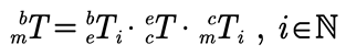
Formula 1, is fixed, which is the hand-eye transformation matrix to be solved. If the position of the AR marker relative to the base coordinate system of the manipulator is unchanged, is also fixed. For a certain state of the manipulator, can be calculated by using the size of the AR marker, the corner coordinates and the camera's internal parameters. Therefore, for a certain stateof the manipulator, the above Equation can be expressed as:
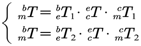
There are two fixed unknown matrices and in the above formula. In order to solve these two unknown matrices, it is necessary to control the manipulator to move to two different states, and the position of the AR marker should be kept unchanged during the movement. Using these two different states, the following equations are listed:
According to the above Equation, the following can be obtained:
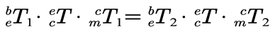
The above Equation can be converted to:
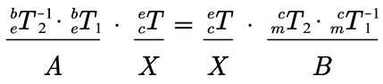
Furthermore, the problem of solving the hand-eye transformation matrixis transformed into the problem of solving the homogeneous Equation AX=XB, where A, X and B are 4 × 4 homogeneous transformation matrices.
To further solve the homogeneous equation AX = XB, the homogeneous transformation matrix in Equation (5) is written in the form of a rotation matrix and translation vector:
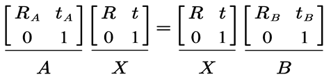
By expanding the above formula, the equations to be solved can be obtained:
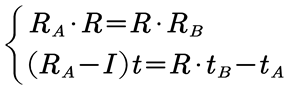
In the above Equation, 、、、 can be measured, and is the unit matrix. There are many solutions to get rotation matrix and translation vectorfrom this equation set, such as the Tsai-Lenz algorithm, Horaud algorithm, Andreff algorithm and Daniilidis algorithm. Next, we will carry out simulation experiments, and find an error analysis method to analyze and optimize the above four hand-eye calibration algorithms.
3. Reprojection error analysis method of calibration algorithms
3.1. Hand-eye calibration algorithm simulation experiments
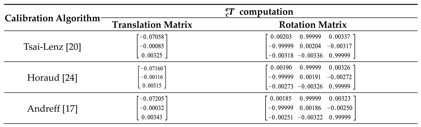
In this paper, ROS and Gazebo simulation platforms are used to build the simulation environment to test the performance of the above four hand-eye calibration algorithms [17,20,24,25]. The true values of and in simulation experiments are shown in Table 1, and the calculation results of each calibration algorithm are shown in Table 2.
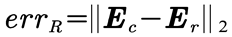
In order to quantitatively evaluate the performance of each calibration algorithm, the translation error of the hand-eye transformation matrix is defined as the two norms of the difference between the calculated valueof the translation vector and the true value . The translation error is measured by the Euclidean distance:
Similarly, the rotation matrix R is first converted to an Euler angle E, and the Euler angle is expressed in vector form as , then the rotation errorof the hand-eye conversion matrix can be defined as:
According to the real values of the parameters in the simulation environment, the statistical results of the translation error and rotation error of the hand-eye transformation matrix calculated by each calibration algorithm are shown in Figure 2. It can be seen from the statistical figure that the translation error of the hand-eye conversion matrix calculated by the Tsai-Lenz and Andreff algorithms is significantly lower than the other two algorithms, but the rotation error of the hand-eye conversion matrix calculated by the Tsai-Lenz algorithm is slightly higher than the other algorithms. Overall, the calibration accuracy of the Tsai-Lenz and Andreff algorithm is relatively high in the simulation environment.
3.2. Heuristic error analysis
It can be seen from Figure 2 that each algorithm still has a certain optimization space. The following is a heuristic error analysis of the simulation results. In the eye-in-hand calibration process, the position of the calibration object relative to the base coordinate system of the manipulator is fixed. Therefore, in theory, should be a fixed value, but according to the coordinate transformation relationship shown in Figure 1, after calculating the hand-eye transformation matrix , can be calculated by the following formula:
The results are shown in Figure 3. It can be seen that the fluctuation range of the corresponding data of the Tsai-Lenz algorithm is small, which is in line with expectations. However, the Andreff algorithm has a large fluctuation range of corresponding data, which is inconsistent with expectations. Therefore, it is unreasonable to judge the error of the hand-eye conversion matrix by the fluctuation degree of data in set C, because the above conjecture actually ignores the influence of the error of on the calculation result of .
3.3. Reprojection error analysis
From the results of heuristic error analysis, it can be seen that and may have some errors, so it is unreasonable to calculate by Equation 10. Since the position of the AR marker is fixed during the calibration process, the following error analysis process considers that is known and fixed.
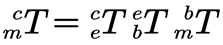
According to the coordinate transformation relationship shown in Figure 1, the pose representation of the AR marker in the camera coordinate system can be obtained:
If the AR marker coordinate system is defined as the world coordinate system, then . According to the pinhole camera imaging model, the conversion relationship between the coordinatesand pixel coordinates in the AR marker coordinate system and the z-axis coordinatein the camera coordinate system can be obtained as follows:
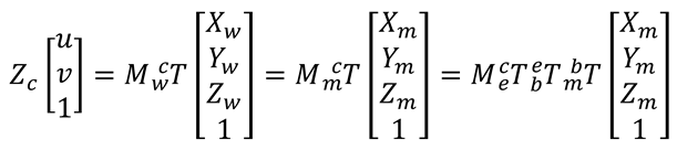
On the basis of the above definition, the coordinates of the originof the AR marker coordinate system in the world coordinate system , so the pixel coordinates of the AR marker center point can be calculated by the following formula:
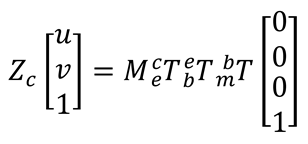
In the above formula, is the inherent property of the camera, is the hand-eye conversion matrix to be calibrated, can be calculated by the forward kinematics equation of the manipulator, and is known and fixed.
Since the translation part of the homogeneous transformation matrix reflects the coordinates of the AR marker center point in the base coordinate system of the manipulator, the function of Equation 13 is actually to remap the coordinates of the AR marker center point into the pixel coordinate system. For a certain position, that the manipulator moves to during the calibration process, the AR mark image captured by the camera is denoted as, and the pixel coordinate after the reprojection of the AR mark center point inis denoted as , then:
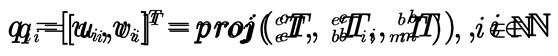
Since the real pixel coordinate of the AR marker center point in can be obtained by corner detection or manual labelling, the reprojection error corresponding tocan be defined as the Euclidean distance between the real pixel coordinates of the AR marker center point and the reprojection coordinates:

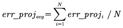
If the manipulator moves to N positions during the hand-eye calibration process, the average reprojection error can be defined as:
According to Equation (15) and Equation (16), the reprojection error of each group of simulation experiment data is calculated. The results are shown in Figure 4. The horizontal line in the figure reflects the average reprojection error of each calibration algorithm. It can be seen that the average reprojection error corresponding to the calculation results of Tsai-Lenz and Andreff algorithms is small, and the fluctuation of the reprojection error of each group of data is relatively small. In addition, from the previous analysis results, the Euclidean distance errors of these two algorithms are relatively small, which proves that the reprojection error can reflect the accuracy of the calibration results to a certain extent. In general, the smaller the reprojection error, the higher the accuracy of the calibration results. In the process of hand-eye calibration of the real manipulator, because the real value of the hand-eye transformation matrix cannot be obtained, the Euclidean distance error of calibration results cannot be calculated, and the reprojection error can be used as the evaluation standard of calibration accuracy.
3.4. Optimization calibration algorithm by minimizing reprojection error analysis
From the statistical results of the Euclidean distance error of each algorithm in Figure 1, it can be seen that even if the hand-eye calibration is carried out in the simulation environment, the translation error of the hand-eye conversion matrix calculated by different calibration algorithms is also quite different, and both are greater than 2mm, which indicates that each calibration algorithm still has a large optimization space.
In the process of hand-eye calibration in the simulation environment, the only error source is the pose calculation error of the AR marker. However, when using the above four common algorithms for calibration, it is considered that the calculated is error-free, resulting in a certain error in the calibration results of each algorithm. In other words, the conventional hand-eye calibration algorithm pays more attention to versatility, and does not use the prior knowledge that the position of the AR marker is fixed in the calibration process, so it is difficult to obtain high-precision calibration results. The definition of the reprojection error of the hand-eye calibration results makes full use of this prior knowledge. According to the previous analysis, the smaller the average reprojection error is, the higher the accuracy of the calibration results. Therefore, by minimizing the reprojection error, the accuracy of the hand-eye calibration results may be improved.
Based on the above analysis, the following exploratory experiments are carried out by controlling variables to test whether smaller average reprojection errors can be obtained by adjusting the parameters in the calibrated hand-eye transformation matrix. In the experiment, the used to calculate the reprojection error takes the real value in Table 1, and the translation parameters calibrated by the Tsai-Lenz algorithm in Table 2 are taken as the initial values. The three translation parameters 、 and are adjusted with the step length of 0.001m, and the adjusted hand-eye transformation matrix is substituted into Equation 15 and Equation 16 to calculate the average reprojection error of each group of samples in the simulation experiment. The experimental results are shown in Figure 5. The purple dotted line reflects the parameter value of the minimum point, and the black dotted line reflects the average reprojection error of the minimum point.
From Figure 5, it can be seen that by adjusting the translation parameters separately, the average reprojection error can indeed be reduced to a certain extent, and the translation parameters calibrated by the Tsai-Lenz algorithm are used as the initial values, which can reduce the search space of the parameters and help quickly find the translation parameters corresponding to the lowest point of the reprojection error. However, when0.03858m, the average reprojection error gets the minimum, but this value obviously deviates from the real value 0.0345m (in Table 2). Therefore, by adjusting x, y, z alone, it is not guaranteed that the translation parameters with higher accuracy can be obtained.
Next, we take 0.001 m as the step length, and adjust x, y, z parameters at the same time. The change rule of reprojection error is shown in Figure 6. The color of the data points in the figure reflects the size of reprojection error. It can be seen that the translation matrix that minimizes the average reprojection error is, and the corresponding average reprojection error 0.69861. According to Equation 8, the corresponding translation error 0.00165 can be calculated. It can be seen from Figure 2 and Figure 4 that the translation error 0.0022 and the average reprojection error 2.96867 of the calibration results are calculated by the Tsai-Lenz algorithm. It can be seen that there is a set of translation parameters ,that can minimize the average reprojection error, and the translation error of this set of parametersis less than the parameters calibrated by the Tsai-Lenz algorithm. In other words, the accuracy of hand-eye calibration results can be improved by simultaneously adjusting the three parameters andto minimize the reprojection error.
In the calibration process, after a certain position of the manipulator is determined, the four parameters in Equation 15 are determined accordingly. Therefore, determines the size of the reprojection . According to Equation 16, if N positions are determined, then the magnitude of the average reprojection error is uniquely determined by , so the mapping function of the hand-eye transformation matrix to the average reprojection error can be defined as:
Furthermore, can be uniquely determined by the translation parameter and the rotation parameter, so the mapping function of the translation and rotation parameters to the average reprojection error can be defined:

Based on the above definition, this paper transforms the optimization problem of the hand-eye conversion matrix into the problem of finding the minimum value of the objective function, and optimizes the hand-eye conversion matrix from the perspective of minimizing the reprojection error.
Next, with a step size of 0.0001m, the three parameters 、 and are adjusted to search for the translation parameter that minimizes the function . The optimal translation parameter (-0.07058, 0.00039, 0.03483), and the corresponding average reprojection error is 0.36084, which is 87.845 % lower than that of the Tsai-Lenz algorithm. The translation erroris 0.0007836 m, which is 64.382 % lower than that of the Tsai-Lenz algorithm.
In the above optimization process, only the translation parameters in the hand-eye conversion matrix are adjusted. Because after many simulation calibration experiments, it is found that the translation parameters have a greater influence on the accuracy of the calibration results than the rotation parameters, and the number of translation parameters is less. In general, only adjusting the translation parameters can obtain ideal calibration results. Of course, if the translation and rotation parameters are adjusted at the same time, higher precision calibration results can be obtained theoretically, but this process will be very time-consuming.
4. Hand-eye calibration algorithm experiment
4.1. Calibration process and results
Under the premise that the internal parameters of the camera have been calibrated, the hand-eye calibration experiment is performed in a real environment. The experimental configuration is shown in Figure 7a, and the AR mark is placed on the workbench in front of the robotic arm. In order to obtain the real position of the AR marker, an auxiliary calibration tool is installed at the end of the manipulator, and then the manipulator is manually controlled to align the top of the calibration tool with the center point of the AR marker (as shown in Figure 7b). Finally, the forward kinematics equation of the manipulator is used to calculate the translation matrix of the center point of the AR marker relative to the base coordinate system of the manipulator. The translation matrix is tr=[0.53514m, 0.00406m, 0.25409m]T
According to the experimental results and error analysis results in the simulation environment, the optimized hand-eye calibration process is as follows:
- Using the auxiliary calibration tool, the real translation matrixof the AR marker coordinate system relative to the base coordinate system of the manipulator is obtained, and then the position of the AR marker is kept unchanged.
- The manipulator is controlled to move to 20 different states where the corner information of the AR marker can be detected, and the corresponding 20 groups of coordinate system transformation data are collected and recorded.
- The mean value of is calculated by using the coordinate transformation data of each group, and the translation matrix in is replaced by to obtain for calculating the reprojection error.
- The Tsai-Lenz algorithm is used to calculate the initial value of the hand-eye transformation matrix , and then its translation parameters are automatically adjusted to minimize the average reprojection error. The optimized hand-eye transformation matrix.
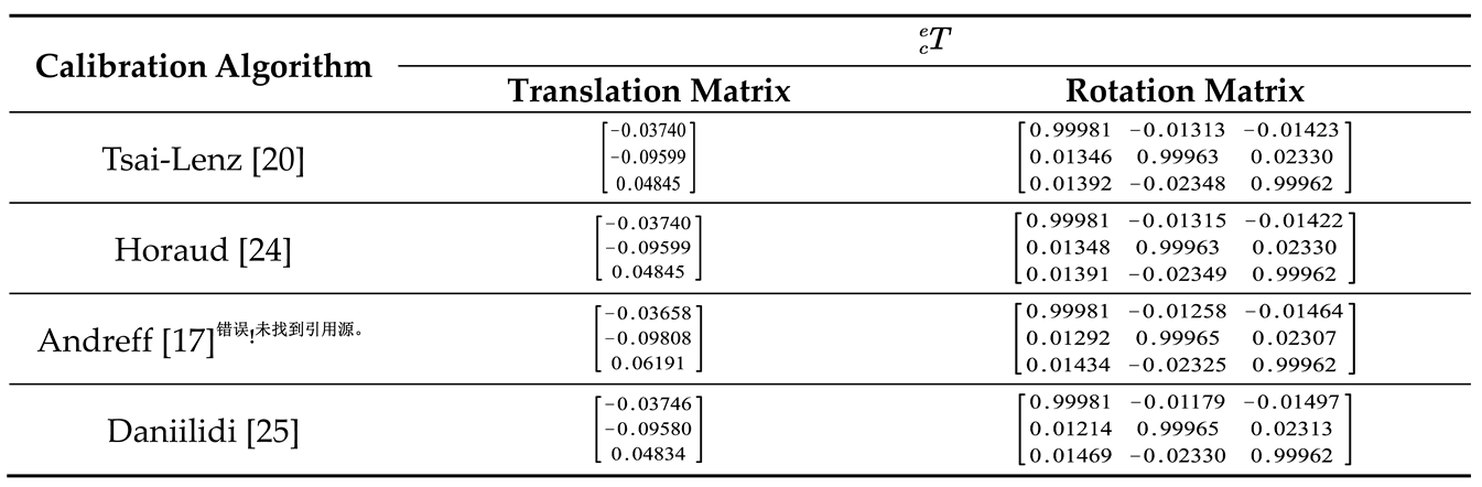
Since it is difficult to obtain the true value of the rotation parameter in in the real environment, the average value is taken when calculating the reprojection error in the above calibration process. According to the above process, the hand-eye calibration experiment is carried out in the real environment, and the hand-eye conversion matrix is calculated by using the four traditional algorithms and the optimized algorithms mentioned above respectively. The results are shown in Table 3.
4.2. Reprojection error analysis
In order to evaluate the performance difference between the traditional algorithm and the optimized algorithm in the real environment, the reprojection errors corresponding to each hand-eye transformation matrix in Table 3 are calculated by using the coordinate transformation data of each group. The results are shown in Figure 8, where the horizontal line reflects the average reprojection error of each method. Because the difference between the hand-eye conversion matrix calculated by the Tsai-Lenz and Horaud algorithms is very small, only the reprojection error corresponding to the Tsai-Lenz algorithm is drawn in the figure. It can be seen that in the real environment, except for the Andreff algorithm, the performance of the other traditional algorithms is close. It is worth mentioning that the average reprojection error of the optimized algorithm is reduced by 44.43% compared with the Tsai-Lenz algorithm.
4.3. Visual positioning error analysis
In the real scene, the calibration results of each algorithm are used to test the positioning accuracy of the manipulator visual positioning. During the test, the AR marker is moved several times, and the state of the manipulator is adjusted to ensure that the corner information of the AR marker can be detected. Then the position pc of the center point of the AR marker in the base coordinate system of the manipulator is calculated by Equation 2. Finally, manually control the manipulator and use the auxiliary calibration tool to obtain the real position pr of the AR marker center point.
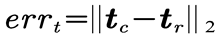
The positioning accuracy of the manipulator in the real scene is quantitatively evaluated, and the visual positioning error is defined as the two norms of the difference between the calculated value pc and the real value pr of the AR mark center point position.
In the actual test process, 10 sets of data are collected, and the hand-eye conversion matrix calculated by each algorithm is used for the visual positioning of the manipulator. The error statistics are shown in Figure 9. The horizontal line in the figure reflects the average visual positioning error corresponding to each algorithm. It can be seen that the optimized hand-eye calibration method can significantly reduce the visual positioning error of the manipulator. Compared with the traditional Tsai-Lenz algorithm, the average visual positioning error is reduced by 50.63%.
5. Summary
When using common algorithms for hand-eye calibration, it is believed that the calculated is error-free, which leads to certain errors in the calibration results of each algorithm. In this paper, the coordinates of the center point of the AR mark are re-projected into the pixel coordinate system, and then compared with the real pixel coordinates of the center point of the AR mark obtained by corner detection or manual labeling, in order to obtain the Euclidean distance between the two coordinates as the basis for error analysis. The method in this paper can reduce the hand-eye calibration error and improve the operation accuracy of the manipulator based on vision.
Author Contributions
Methodology, Peng, G. and Ren, Z.; software, Gao, Q.; validation, Gao, Q.; investigation, Ren, Z and Gao, Q.; data curation, Ren, Z and Gao, Q.; project administration, Peng, G.; structural optimization and writing improvement, Fan, Z. All authors have read and agreed to the published version of the manuscript.
Funding
This work was supported by Hubei Province Core Technology for Bridging Development Gaps Project (HBSNYT202213), Hubei Province Unveiling Science and Technology Project (2021BEC008), and Hubei Province Natural Science Foundation of China (No. 2019CFB526).
Institutional Review Board Statement
Not applicable.
Informed Consent Statement
Not applicable.
Data Availability Statement
Data sharing not applicable.
Conflicts of Interest
The authors declare no conflict of interest.
References
- Ge, Pengxiang, et al. "Multivision Sensor Extrinsic Calibration Method With Non-Overlapping Fields of View Using Encoded 1D Target." IEEE Sensors Journal 22.13 (2022): 13519-13528. [CrossRef]
- Bu, Lingbin, et al. "Concentric circle grids for camera calibration with considering lens distortion." Optics and Lasers in Engineering 140 (2021): 106527. [CrossRef]
- Chen, Xiangcheng, et al. "Camera calibration with global LBP-coded phase-shifting wedge grating arrays." Optics and Lasers in Engineering 136 (2021): 106314. [CrossRef]
- Zhang, Zhengyou. "A flexible new technique for camera calibration." IEEE Transactions on pattern analysis and machine intelligence 22.11 (2000): 1330-1334. [CrossRef]
- Hartley, Richard I. "Self-calibration of stationary cameras." International journal of computer vision 22 (1997): 5-23. [CrossRef]
- Li, Mengxiang. "Camera calibration of a head-eye system for active vision." Computer Vision—ECCV'94: Third European Conference on Computer Vision Stockholm, Sweden, May 2–6, 1994 Proceedings, Volume I 3. Springer Berlin Heidelberg, 1994. [CrossRef]
- Hartley, Richard I. "Projective reconstruction and invariants from multiple images." IEEE Transactions on Pattern Analysis and Machine Intelligence 16.10 (1994): 1036-1041. [CrossRef]
- Pollefeys, Marc, Luc Van Gool, and Andre Oosterlinck. "The modulus constraint: a new constraint self-calibration." Proceedings of 13th International Conference on Pattern Recognition. Vol. 1. IEEE, 1996. [CrossRef]
- Triggs, Bill. "Autocalibration and the absolute quadric." Proceedings of IEEE Computer Society Conference on Computer Vision and Pattern Recognition. IEEE, 1997. [CrossRef]
- Heyden, Anders, and K. Astrom. "Flexible calibration: Minimal cases for auto-calibration." Proceedings of the Seventh IEEE International Conference on Computer Vision. Vol. 1. IEEE, 1999. [CrossRef]
- Pollefeys, Marc, Reinhard Koch, and Luc Van Gool. "Self-calibration and metric reconstruction inspite of varying and unknown intrinsic camera parameters." International journal of computer vision 32.1 (1999): 7-25. [CrossRef]
- Pollefeys, Marc. Self-calibration and metric 3D reconstruction from uncalibrated image sequences. Diss. PhD thesis, ESAT-PSI, KU Leuven, 1999.
- Hartley, Richard I., et al. "Camera calibration and the search for infinity." Proceedings of the Seventh IEEE International Conference on Computer Vision. Vol. 1. IEEE, 1999. [CrossRef]
- Wenyu Chen, Jia Du, Wei Xiong, Yue Wang, Shueching Chia, Bingbing Liu, Jierong Cheng, Ying Gu. "A Noise-Tolerant Algorithm for Robot-Sensor Calibration Using a Planar Disk of Arbitrary 3-D Orientation," in IEEE Transactions on Automation Science and Engineering, vol. 15, no. 1, pp. 251-263, Jan. 2018. [CrossRef]
- Mingyang Li, Zhijiang Du, Xiaoxing Ma, Wei Dong, Yongzhuo Gao. A robot hand-eye calibration method of line laser sensor based on 3D reconstruction. Robotics and Computer-Integrated Manufacturing. Volume 71, October 2021, 102136. [CrossRef]
- Yuan Zhang, Zhicheng Qiu, and Xianmin Zhang. Calibration method for hand-eye system with rotation and translation couplings. Applied Optics, Vol. 58, Issue 20, pp. 5375-5387, 2019. [CrossRef]
- Andreff, Nicolas, Radu Horaud, and Bernard Espiau. "On-line hand-eye calibration." Second International Conference on 3-D Digital Imaging and Modeling (Cat. No. PR00062). IEEE, 1999.
- Tabb, Amy, and Khalil M. Ahmad Yousef. "Solving the robot-world hand-eye (s) calibration problem with iterative methods." Machine Vision and Applications 28.5-6 (2017): 569-590. [CrossRef]
- Jianfeng Jiang, Xiao Luo, Shijie Xu, Qingsheng Luo, Minghao Li. "Hand-Eye Calibration of EOD Robot by Solving the AXB = YCZD Problem," in IEEE Access, vol. 10, pp. 3415-3429, 2022. [CrossRef]
- Tsai, Roger Y., and Reimar K. Lenz. "A new technique for fully autonomous and efficient 3 d robotics hand/eye calibration." IEEE Transactions on robotics and automation 5.3 (1989): 345-358. [CrossRef]
- Yan Liu, Qinglin Wang, Yuan Li. A method for hand-eye calibration of a robot vision measuring system. 2015 10th Asian Control Conference (ASCC), Kota Kinabalu, Malaysia, 2015, pp. 1-6. [CrossRef]
- Yanbiao Zou, Xiangzhi Chen. "Hand–eye calibration of arc welding robot and laser vision sensor through semidefinite programming", Industrial Robot, Vol. 45 No. 5, pp. 597-610, 2019. [CrossRef]
- Shichao Deng, Feng Mei, Long Yang, Chenguang Liang, Yingliang Jiang, Gaoxing Yu, Yihai Chen. "Research on the Hand-eye calibration Method Based on Monocular Robot". Journal of Physics: Conference Series, Volume 1820, 2021 International Conference on Mechanical Engineering, Intelligent Manufacturing and Automation Technology (MEMAT), January 15-17, 2021, Guilin, China. [CrossRef]
- Horaud, Radu, and Fadi Dornaika. "Hand-eye calibration." The international journal of robotics research 14.3 (1995): 195-210. [CrossRef]
- Daniilidis, Konstantinos. "Hand-eye calibration using dual quaternions." The International Journal of Robotics Research 18.3 (1999): 286-298. [CrossRef]
Short Biography of Authors
Gang Peng received the doctoral degree from the Department of control science and engineering of Huazhong University of Science and Technology (HUST) in 2002. Currently, he is an associate professor in the Department of Automatic Control, School of Artificial Intelligence and Automation, HUST. He is also a senior member of the China Embedded System Industry Alliance and the China Software Industry Embedded System Association, a senior member of the Chinese Electronics Association, and a member of the Intelligent Robot Professional Committee of Chinese Association for Artificial Intelligence. His research interests include intelligent robots, machine vision, multi-sensor fusion, machine learning and artificial intelligence.
Zhenyu Ren received his bachelor degree in school of automation from Hainan University, China, in 2018. He received master’s degree from the Department of Automatic Control, School of Artificial Intelligence and Automation, Huazhong University of Science and Technology. His research interests include intelligent robots and perception algorithms.
Qiang Gao received his bachelor degree in School of Electrical and Information Engineering, Zhengzhou University, China, in 2022. He is currently a graduate student at the Department of Automatic Control, School of Artificial Intelligence and Automation, Huazhong University of Science and Technology, Wuhan, China. His research interests are intelligent robots and perception algorithms.
Zhun Fan received his B.S. and M.S. degrees in Control Engineering from the Huazhong University of Science and Technology, Wuhan, China, in 1995 and 2000, respectively, and his Ph.D. degree in Electrical and Computer Engineering from Michigan State University, Lansing, MI, USA, in 2004. He is currently a Full Professor at Shantou University (STU), Shantou, China. He also serves as the Head of the Department of Electrical Engineering and the Director of the Guangdong Provincial Key Laboratory of Digital Signal and Image Processing. His major research interests include intelligent control and robotic systems, robot vision and cognition.
Figure 1.
Coordinate system and transformation relationship diagram in the process of hand-eye calibration.
Figure 1.
Coordinate system and transformation relationship diagram in the process of hand-eye calibration.
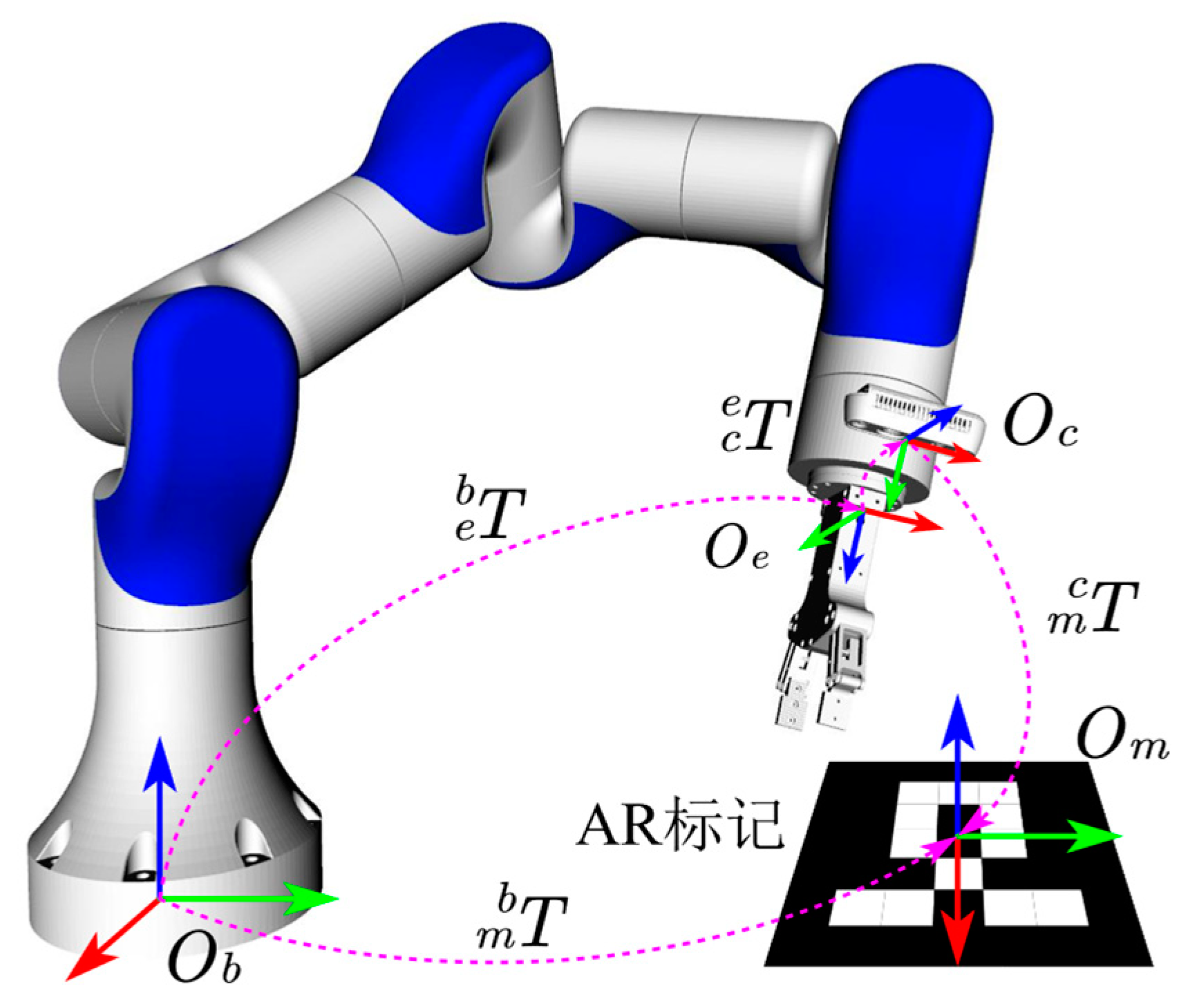
Figure 2.
Euclidean distance error statistics of each calibration algorithm (according to the real values of the parameters in the simulation environment).
Figure 2.
Euclidean distance error statistics of each calibration algorithm (according to the real values of the parameters in the simulation environment).
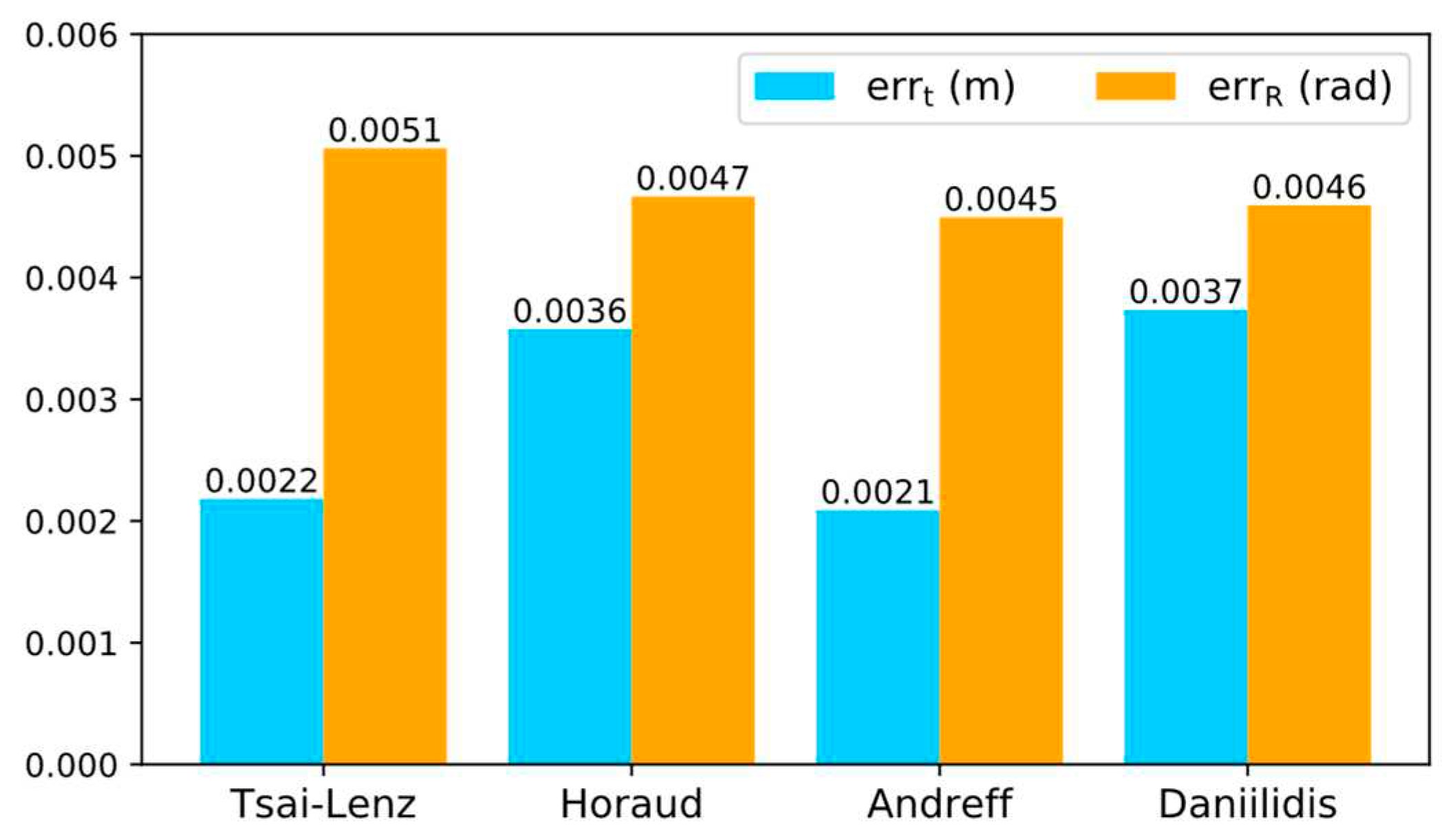
Figure 3.
Visualization of fluctuation range of parameters in translation matrix of .
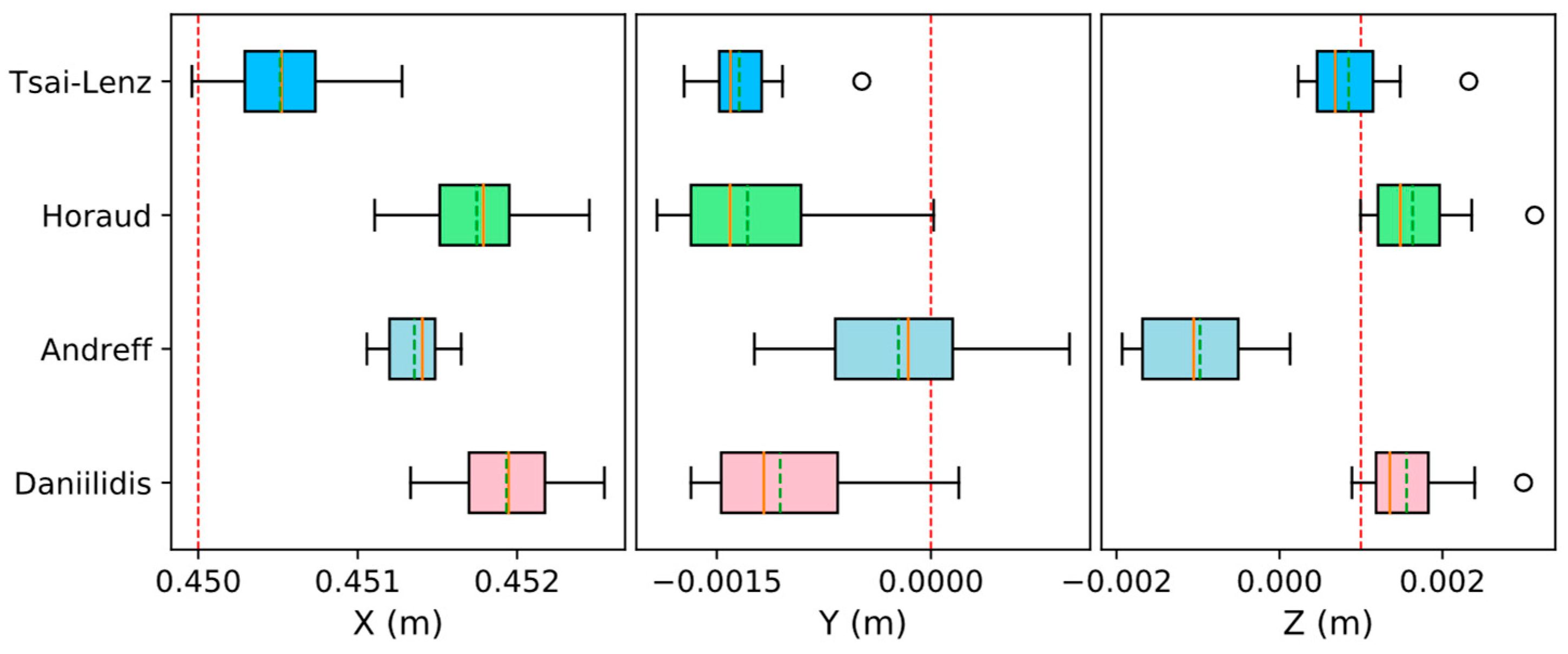
Figure 4.
Reprojection Error Comparison (Simulation Environment).
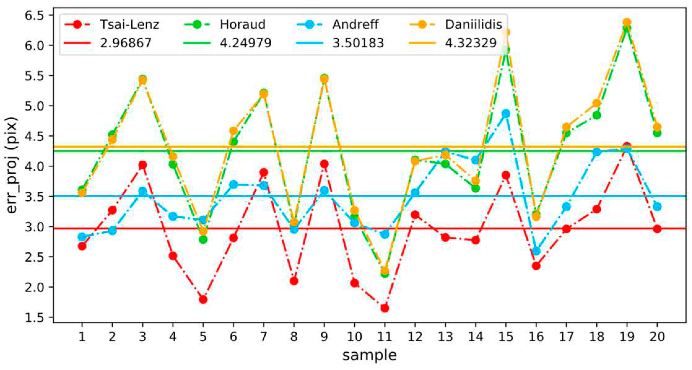
Figure 5.
Change curves of reprojection error when adjusting x, y and z respectively.
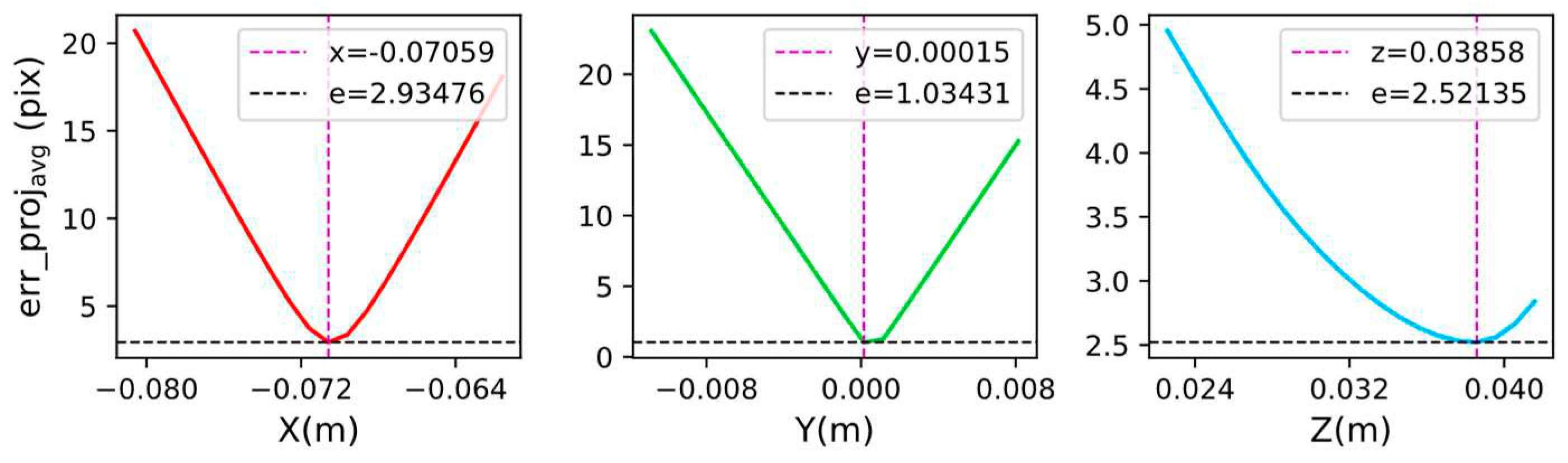
Figure 6.
Variation of reprojection error when adjusting x, y, z parameters simultaneously.
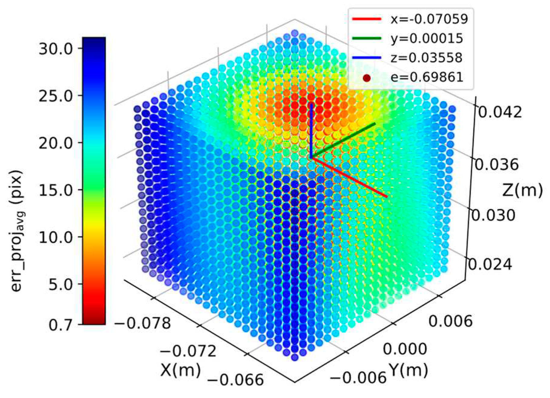
Figure 7.
Hand-eye calibration experiment configuration and AR marker center point acquisition:(a) Hand-eye calibration experiment configuration (b) AR mark center point acquisition.
Figure 7.
Hand-eye calibration experiment configuration and AR marker center point acquisition:(a) Hand-eye calibration experiment configuration (b) AR mark center point acquisition.
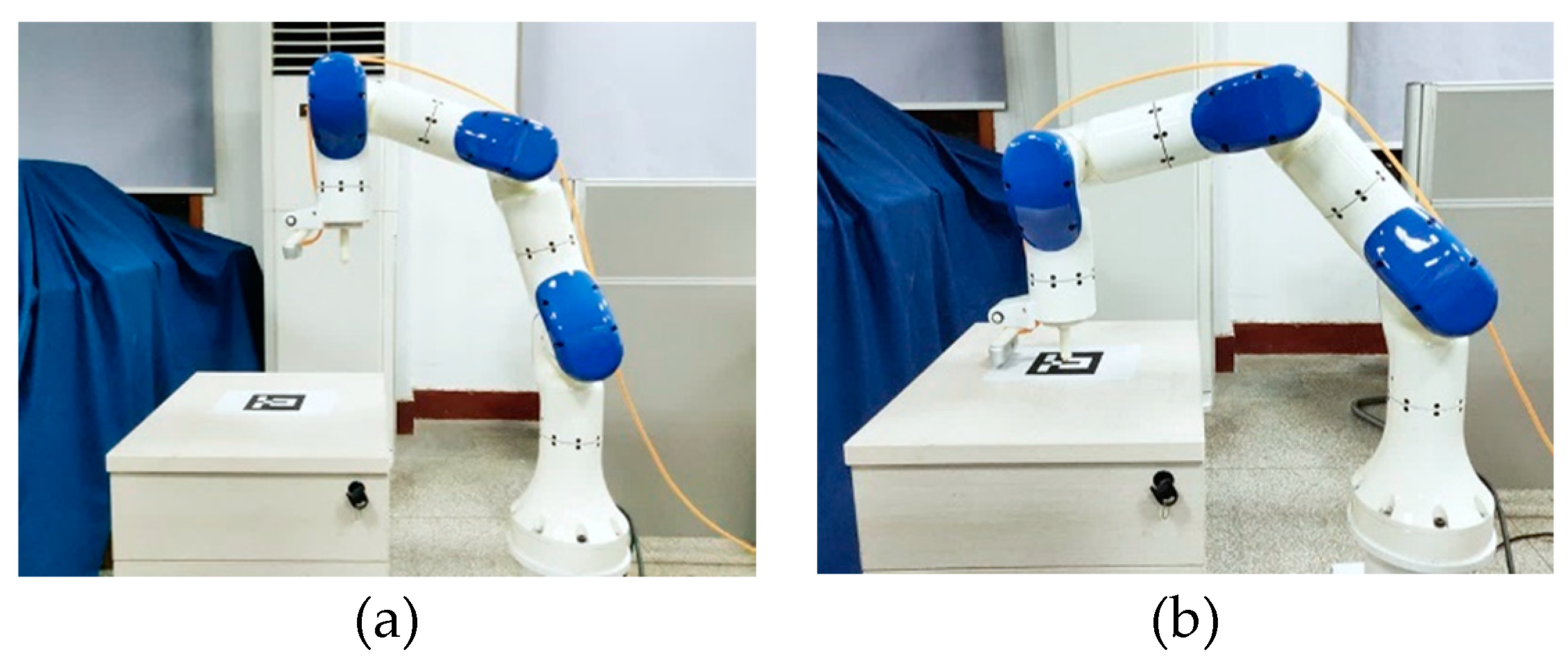
Figure 8.
Comparison of reprojection errors.
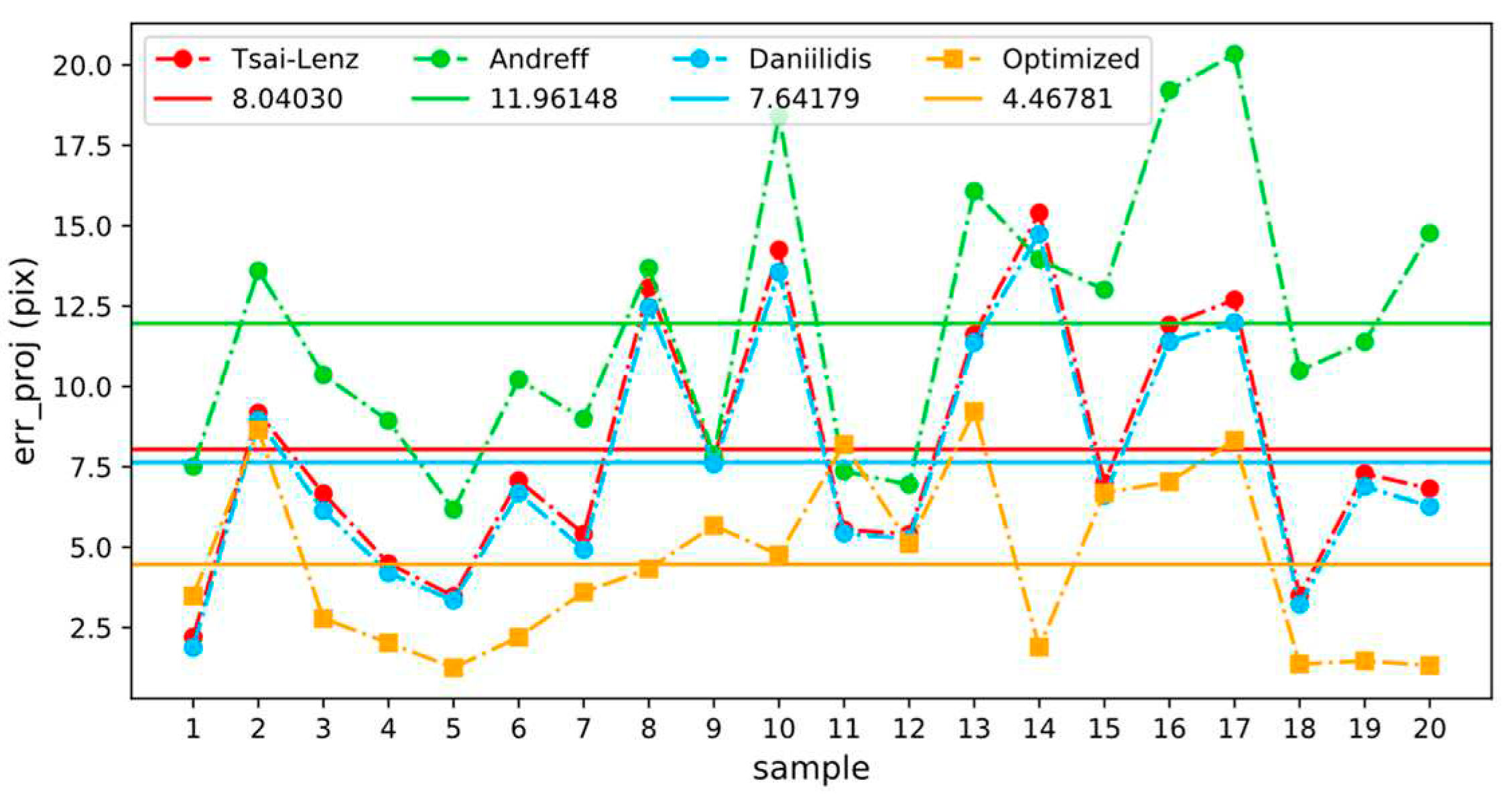
Figure 9.
Visual positioning error comparison.
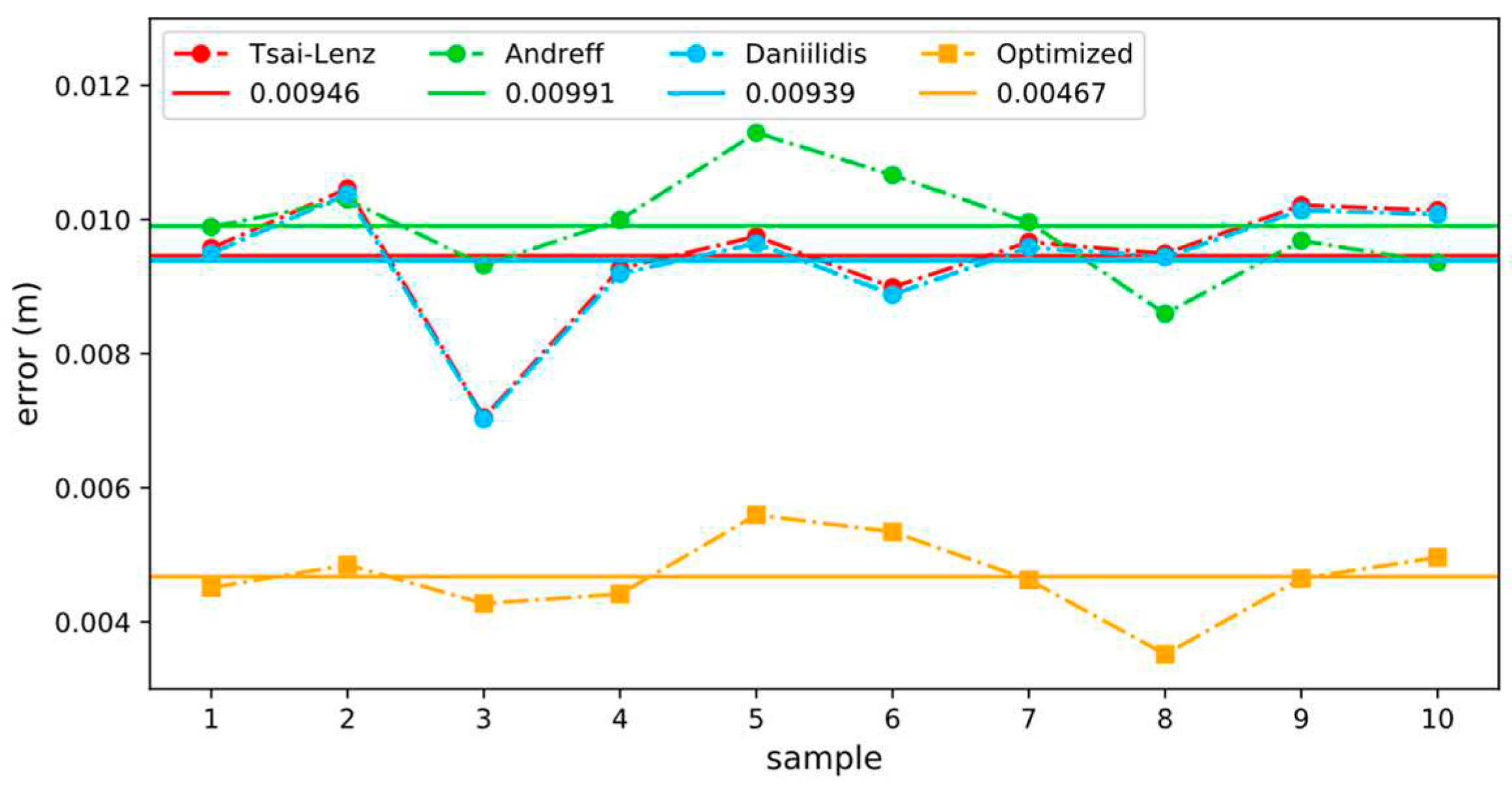

Table 1.
True values of parameters in a simulation environment.
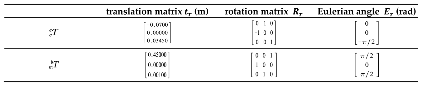 |
Table 2.
Hand-eye transformation matrix calculated by calibration algorithms in a simulation environment.
Table 2.
Hand-eye transformation matrix calculated by calibration algorithms in a simulation environment.
|
Table 3.
Hand-eye transformation matrix calculated by calibration algorithms in a real environment.
|
Disclaimer/Publisher’s Note: The statements, opinions and data contained in all publications are solely those of the individual author(s) and contributor(s) and not of MDPI and/or the editor(s). MDPI and/or the editor(s) disclaim responsibility for any injury to people or property resulting from any ideas, methods, instructions or products referred to in the content. |
© 2023 by the authors. Licensee MDPI, Basel, Switzerland. This article is an open access article distributed under the terms and conditions of the Creative Commons Attribution (CC BY) license (http://creativecommons.org/licenses/by/4.0/).
Copyright: This open access article is published under a Creative Commons CC BY 4.0 license, which permit the free download, distribution, and reuse, provided that the author and preprint are cited in any reuse.


