Submitted:
21 October 2023
Posted:
23 October 2023
You are already at the latest version
Abstract
The utilization of fuel cells (FC) in automotive technology has experienced significant growth in recent years. Fuel cell hybrid electric vehicles (FCHEVs) are powered by a combination of fuel cells, batteries, or/and ultracapacitors (UCs). By integrating power converters with these power sources, the FCHEV system can overcome the limitations of using them separately. The performance of an FCHEV is influenced by the efficiency of the power electronics converter controller, as well as the technical efficiency of the power sources. FCHEVs need intricate energy management systems (EMSs) to function effectively. Poor EMS can lead to low efficiency and accelerated fuel cell and battery degradation. The literature discussed various types of EMSs, such as equivalent consumption minimization strategy, classical PI controller, fuzzy logic controller, and Mutative Fuzzy Logic Controller (MFLC). However, comparing different EMSs can be challenging due to the varying vehicle and system parameters, which might lead to false claims being made regarding system performance. This research aims to categorize and discuss the various topologies of FCHEVs, highlighting their pros and cons, and comparing several EMSs based on performance metrics such as State of Charge (SOC) and FC deterioration.
Keywords:
Fuel cell hybrid electric vehicle
; Topology
; Energy management system
; Fuzzy logic
; Ultracapacitor
; Battery
1. Introduction
The world's transportation industry currently relies heavily on fossil fuels as its main energy source. This reliance leads to air pollution, depletion of the ozone layer, and exacerbation of global warming. Overuse of fossil fuels in transportation is also causing the depletion of underground petroleum reserves. In 2014, data from the US Energy Information Administration (EIA) showed that the transportation industry accounted for 55% of global energy consumption and 30.9% of carbon dioxide emissions [1]. If a new solution for the transportation industry is not developed, this tendency will continue. Figure 1 and Figure 2 depict recent energy use and carbon dioxide emissions by various industries, as well as predictions for future years [2].
With the rising global emphasis on environmental protection intensifying and energy conservation, the exploration of vehicles powered by non-traditional energy sources has become a major area of research for automakers and academic institutes. The Fuel Cell Electric Vehicle (FCEV) is viewed as having great potential for zero emissions and great energy efficiency [3]. It offers a longer range with a quicker refueling time than an Electric-only vehicle (EV) [4]. However, the fuel cell system falls short in supplying the necessary power during dynamic states like start-up, climbing, or acceleration, because the reaction gas response rate can't keep up with changes in load [5]. Additionally, chemical energy is directly transformed into electrical energy within the operation of the Fuel Cell System (FCS), allowing for one-way power output, making it unable to retain the energy produced during slowing down or braking [6]. Deficiencies in the FCS can negatively impact a FC vehicle's economy, dependability, and durability [7]. To counteract these issues, FCEVs are often coupled with a supplementary energy storage system, like a battery or ultra-capacitor (UC), to form a FCHEV system [8,9,10].
The hybrid system can successfully address the challenges previously mentioned. However, the presence of many energy sources leads to a more complex working mode for the power system. As a result, developing an efficient, reliable, and stable method for utilizing numerous energy sources has become a key technology for the FCHEV system [11,12]. This key technology, known as the Energy Management Strategy (EMS), has a direct impact on the optimal operating point of each energy source to fulfill the demand for electricity.
Additionally, the EMS helps to distribute power effectively in response to changing demand, reducing fuel consumption, improving system's efficiency, and extending the FCHEV's operational life [13]. Hence, studying EMSs is vital for the FCHEV. This article focuses on analyzing the current research that pertains to the structures and energy management mechanisms adopted for FCHEVs. A review of different forms of vehicle technology is given in Section 2. Different FCHEV topologies are categorized in Section 3 where their features are presented in detail. Section 4 illustrates the present state of EMSs research whereas a comprehensive comparison between different EMS is presented in Section 5. Finally, the paper is concluded in Section 6.
2. A comprehensive Overview of the Developments in Vehicle Technology
The advancements in vehicle technology have resulted in the creation of transportation systems that are cost-effective, environmentally friendly, and innovative. The development of these systems can be broken down into three categories: Internal Combustion Engine Vehicles (ICEV), Hybrid Electric Vehicles (HEV), and Electric Vehicles (EV). ICEVs rely solely on gasoline-powered internal combustion engines, while EVs utilize electricity as their primary energy source through batteries, ultracapacitors, fuel cells, etc. HEVs are a combination of both ICEVs and EVs. As shown in Figure 3, the categorization of vehicles into different types of hybrids is determined by the hybridization factor indicated in Equation (1) [14,15], which is represented as the proportion of electric power to the total power.
This is an example of an equation:
where, is the electric power and is the internal combustion engine power.
2.1. Internal Combustion Engine Vehicle
The energy stored in fossil fuels is turned into kinetic energy that propels the vehicle by the combustion chamber ICEV. During the conversion process, heat is produced as an unintended consequence of the conversion mechanism and is emitted into the environment. There are two kinds of ICEVs: traditional ones without an electric motor and micro hybrid electric vehicles (micro-HEVs) that have low-voltage electric motors. Traditional ICEVs are powered exclusively by gasoline and have the weakest fuel efficiency but emit the most harmful exhaust and heat. Micro-HEVs features an electric motor with a voltage of roughly 12-14 volts, providing 5 kW of power in conjunction with the internal combustion engine [16]. The motor only assists the ICE in starting and doesn't provide any driving power. This design allows for the ICE to be shut off when the vehicle is coasting, braking, or stopped, resulting in improved fuel economy of 5-15%. One instance of this type of vehicle is Citroën C3 made by Citroën company [17].
2.2. Hybrid Electric Vehicle
HEVs utilize a combination of two different energy sources, ICE and Electric Motor (EM), to achieve maximum efficiency while operating the vehicle. There are three main categories of HEVs: mild HEVs, full HEVs, and plug-in HEVs. Mild HEVs offer similar benefits to micro-HEVs, but have a higher EM power output ranging from 7 to 12 kW/150 V. Both the EM and ICE work together to drive the car, increasing fuel efficiency by up to 30% [18]. The downside is that the EM and ICE cannot function independently since they share the same shaft [19]. Honda Civic, Honda Accord, Saturn Vue 2009, and GMC Sierra 1500 truck are a few examples of commercial mild-HEVs.
Most automakers have shifted towards the production of full-HEVs to meet the demand for greater fuel efficiency. This kind of HEV is equipped with a dual power path for both the ICE and electric motor, allowing for independent or combined operation. Fuel economy can be enhanced by 40% without any loss in performance by utilizing this technology. Full-HEVs typically make use of large energy storage systems (ESS), like UC or batteries, and the electric motor operates at approximately 50 kW/330 V. The full-HEV system is categorized to four distinct types: series HEV, parallel HEV, series-parallel HEV, and complex HEV.
Vehicles classified as series full-HEVs rely on the electric motor as the primary source of propulsion, like battery electric vehicles (BEVs). These vehicles feature a high-powered internal combustion engine generator to recharge the battery. This design offers the benefit of reducing the size of the energy storage system, due to the generator power and fuel capacity. Series full-HEVs can effectively use the generated energy during regenerative braking to recharge the ESS. However, this design choice results in lower vehicle efficiency, approximately 25.7%, which is the lowest among full-HEV types. Despite this, the series full-HEV is ideal for city driving patterns with frequent stops and starts [2].
Parallel full-HEVs utilize separate propulsion systems for the ICE and the EM, which are joined through a mechanical coupler. This enhances the vehicle's fuel efficiency by up to 43.4%, but the downside is a lower battery capacity. Despite this, the parallel full-HEV is still favored over the series full-HEV due to its higher efficiency and the reduced size of its electric motor and EMSs [2].
The full-HEV vehicles that have a series-parallel configuration utilize both a mechanical and an electrical coupler to combine the ICE and the EM. This configuration offers the best of both series and parallel full-HEV systems, but the setup can be quite intricate and expensive.
The complex full-HEV configuration shares similarities with series-parallel full-HEV, but with the added advantage of power converters linked to the EM, making it a more efficient and controlled system. However, it's more complicated and expensive. All full-HEV structures permit vehicle manufacturers to utilize existing technologies like motors, engines, and ESS, which helps to keep the cost of vehicles low [20,21,22]. Examples of commercially available full hybrids, like the Nissan Tino, Lexus LS 600 h, and Toyota Prius, utilize the series-parallel full-HEV configuration, while others, such as the Ford Escape, Honda Civic hybrid, and Honda Insight, utilize the parallel full-HEV configuration.
Plug-in HEVs are another form of HEV that enable to charge of the energy storage system from an external source. Besides the ICS, recharging the ESS is made possible by linking it to the electrical grid. This feature allows for the use of a larger ESS, thereby extending the vehicle's range. Figure 4 displays a schematic diagram of a series-parallel HEV [23].
2.3. All Electric Vehicle
AEVs rely solely on electrical energy for their operation. There are six power transfer methods for AEVs have been studied and noted in [24]. The AEVs can be divided into three categories based on their energy source: Battery Electric Vehicles (BEVs), FCEVs, and FCHEVs. The BEVs and FCEVs are similar and have only one power source, while FCHEVs have a hybrid power source composed of both battery and FC, or UC and FC, or UC, battery, and FC.
2.3.1. Battery electric vehicle
BEVs use batteries as their power source. The battery is located inside the vehicle and can be charged either on-board or off-board. This configuration of vehicle is characterized by its simple mechanical drivetrain, making the vehicle lighter and reducing energy conversion losses. However, the efficiency of BEVs is impacted negatively due to the increase in armature current flow during acceleration, which requires a high level of traction torque [20,21,22,25]. BEVs have a limited driving range and peak speed, making them suitable for stop-and-start driving pattern (city driving). The peak speed and driving range can be enhanced by adding a gearbox, but this would compromise the vehicle's efficiency. Without a gearbox, the basic BEV offers enhanced efficiency owing to its fewer moving parts and lower inertia [17].
2.3.2. Fuel cell electric vehicle
Like BEVs, FCEVs are equipped with an all-electric powertrain, with the difference being that the energy source for an FCEV is a hydrogen-fed fuel cell stack, producing only water and heat as emissions. Because of this, FCEVs are considered zero-emission vehicles. Polymer electrolyte membrane fuel cells (PEMFCs) are the best choice for vehicles due to their high-power density, low operating temperature (60-80°C), low pressure, and resistance to corrosion over other fuel cell types [26,27]. The hydrogen used in FCEVs can be obtained either by storing it in a tank utilized on the vehicle or by processing it from fuel. Figure 5 depicts the drivetrain configuration used for FCEVs [28]. FCEVs are adequate for constant power source, except for sudden changes in loading, making them ideal for slower vehicles like forklifts, submarines, trams, buses, and vehicles used for handling materials. Currently, high-speed vehicles are now being manufactured with fuel cells as well, with notable companies such as Honda, Hyundai, and Toyota creating high-performance FCs to elevate their vehicles' capabilities. Various EMS are being adopted to enhance fuel economy, minimize energy dissipation, and increase vehicle’s efficiency.
2.3.3. Fuel cell hybrid electric vehicle
The enhancement of FCEV power system leads to a new type known as the FCHEV. Th design of FCHEV employs a supplementary ESS to assist the FC, where a battery pack or an ultracapacitor bank is used for charging and discharging, aligning with supply and load conditions. When using a fuel cell serves as the primary source of energy and a battery, ultracapacitor, or both as the ESS in a FCHEV, certain considerations must be taken to guarantee effective and seamless operation. These considerations include the reliability, weight, and dimensions of the power converter, as well as its efficiency, electromagnetic interference (EMI), and fluctuations in output current and voltage. Figure 6 displays a standard power system of an FCHEV [29].
3. Topological Classification
The battery and UC are superior to other energy sources in terms of their high-power density and easily manageable energy storage capabilities [30]. The FCHEV topologies are categorized into three groups based on their auxiliary source configurations, which are (a) FCS with Battery hybridization, (b) FCS with UC hybridization, and (c) FCS with Battery and UC hybridization. In this section, the general and summarized characteristics of each topology are presented to aid in the selection of the most appropriate configuration.
3.1. Hybrid FCS and Battery system
The most prevalent topology for the FCHEV is the combination of FCS and battery, which has characterized by its established industry chain and low production costs [31,32,33]. This configuration has the fuel cell energy, serving as the principal energy source, supplemented by the battery during peak demand or sudden load change and recapturing energy during regenerative braking mode. This topology helps reduce the impact of high current required from the FCS during high-load conditions or sudden load change and also improves the overall efficiency [34,35]. The connection between the FCS and the battery can be differentiated into four categories, including a direct parallel connection of both FC and battery, direct parallel linking of only the FC, direct parallel linking of only the battery bank, and an indirect parallel linking of both FC and battery. Each connection approach possesses its own distinctive features, which can impact the durability and the cost of FCHEV. Further analysis of this hybridization will focus on these different connections.
3.1.1. Direct parallel connection of both FC and battery
The FCS, battery, and DC bus are directly connected in parallel without using any DC/DC power converter as illustrated in Figure 7 [36]. To transform the DC voltage from the FCS and battery to the AC voltage needed by the motor, a DC/AC converter is utilized [19]. This connection method offers several benefits, including a simple design, minimal space requirements, cost-effectiveness [37,38], and possibility for implementing sensor less controllers [39]. Nevertheless, the drawback of this structure is that when the load varies, the output voltage from the energy sources is frequently less than what the DC bus needs [40]. This action leads to a significant voltage variation at DC bus and lessening the reliability and loss of control of the power system. Additional diodes play a crucial role in maintaining the stability of the power system by preventing the DC bus voltage from surpassing the FC output voltage, which can cause backward current flow and power system failure [41,42]. However, this extra protection will lower the power system's overall efficiency.
3.1.2. Direct connection of FCS
The FC is directly connected to the motor's DC bus in Figure 8, while the battery is linked to the DC bus through a DC/DC bi-directional converter (BDC). The BDC's basic function is to maintain a stable output voltage [43]. One of the most attractive BDC topologies is the Dual Active Bridge [44]. The simplicity of connection and straightforwardness of implementation are benefits of this connection approach. Additionally, the BDC enables the adoption of batteries with low voltage level and enhances the battery's consumption [45]. Nevertheless, using DC/DC converter decreases the system efficiency. As a result of the direct connection of FCS to DC bus, the FCS terminal voltage determines voltage level of the DC bus. This means that variations in FCS power can cause significant fluctuations in the bus voltage level, particularly in urban environments characterized by frequent and heavy load variations. The misalignment between the voltage levels of FCS and bus voltage can cause a reduction in FCHEV performance.
3.1.3. Direct connection of battery packs
The FCS is linked to the motor's DC bus through a unidirectional DC/DC converter (UDC) in Figure 9 [46]. Meanwhile, the battery is directly connected to the motor's DC bus. The presence of the UDC reduces voltage fluctuations during power fluctuations on the low voltage end, leading to a reduced output power requirement for FCS and improved dynamic characteristics. The UDC additionally restricts the FCS output power to a secure level, which enhances its efficiency and extends the lifespan of FCS. Connecting the battery pack directly to the DC bus makes the battery govern the bus voltage level [47]. If the remaining capacity of battery pack is inadequate, it won't be able to sustain bus voltage with acceptable range following a deep discharge. Then, this highlights the importance of selecting a high-performing battery when using this connection method.
3.1.4. Indirect connection of both FC and battery
Figure 10 depicts the connection between FCS and motor DC bus through a UDC, and the connection between battery packs and motor DC bus through a BDC. This configuration helps in minimizing the adverse impact of power fluctuations on FCS, and improves the battery's power delivered and absorbed control [48]. The connection can also regulate bus voltage level. In addition, the voltage matching requirements for both FCS and battery are significantly reduced and simplifies the control of each component's operation [49]. However, negatively impacts the overall efficiency of the system, increasing layout space, manufacturing cost, ripple current, and the need for a larger filter capacitor [50]. To solve these issues, multi-port DC/DC converters could be utilized [51,52]. This architecture is typically utilized for very demanding power systems. Table 1 provides a comprehensive comparison between the advantages and disadvantages of the four topologies.
3.2. FCS + UC Hybridization
The UC boasts several advantages over batteries, including a greater power density, exceptional cold start operation, a longer theoretical lifespan, efficient charging and discharging, and minimal loss [53,54,55,56,57]. One of the UC's key features is its quick discharge speed, which dramatically improves a vehicle's power during acceleration [58]. As a result, the pairing of a fuel cell system with an ultracapacitor, known as FCS + UC hybridization, has garnered attention. The connection process of this hybridization is similar to that of hybrid integration of FCS and battery, with comparable advantages and disadvantages among connection methods. Although UCs possess several advantages over batteries, they have several drawbacks as well. The energy density of UCs is lower compared to batteries, which restricts its storage capacity. Additionally, its safety voltage is also lower than that of batteries [59,60]. Furthermore, the high discharge rate and rapid charging, make it challenging to control [61]. Controlling the current during charging and discharging, as well as prolonging the discharge time, are critical for the widespread implementation and use of this technology.
3.3. FCS + Battery + UC Hybridization
For a vehicle to exhibit optimal acceleration, it requires both high power density and high-energy density [62]. Taking advantage of the complementary benefits offered by batteries and UCs, the combination of FCS, Battery, and UC hybridization results in a more efficient distribution of energy under various operating conditions [36,63]. Schaltz et al. [64] conducted a study on various designs of the FCHEV and found that, FCS + Battery packs + UC system excelled in reducing both mass and volume, enhancing efficiency, and increasing battery pack's lifespan, all while maintaining the same power as the FCS. Similarly, Xie et al. The FCS + Battery unit's + UC hybrid configuration is introduced un [65], as portrayed in Figure 11a, where the FCS offers the load's average power, the battery supplies supplementary power during high-power load, and the UC delivers transient power and stabilizes the bus voltage. Additionally, the current generated while braking is absorbed by UC to protect the battery from high current impacts. Figure 11b [66] and Figure 11c [67] show hybridization topologies which are beneficial in increasing the FCS' lifespan.
In Figure 11a, the connection of the FCS to a UDC, helps to regulate the rapid changes in voltage and current in the DC bus, ultimately leading to a longer lifespan for the FCS. FCS + Battery packs + UC hybrid configuration is seen as the optimal solution for energy recovery during braking and for meeting the power needs during starting, hill-climbing, and acceleration [68]. However, this hybridization approach comes with challenges such as high production costs, difficulty in matching energy sources' parameters, and complex energy management systems. As a result, this combination is still technically underdeveloped and challenging to implement on a commercial scale. In conclusion, each topology has its unique features, and the best option can be determined by evaluating the characteristics of each topology and reviewing relevant models, as outlined in Table 2.
3.4. Wireless Charging of FC-Battery-UC Based HEV
The innovative system boasts a FC as its primary power source, owing to its exceptional energy density. This is complemented by the combination of a UC and batteries, which provide a harmonious balance between high power output and the ability to handle unexpected power fluctuations, as well as solve the problem of cold starting. As shown in Figure 12, the FC with its unidirectional power flow is connected to the DC Bus through a DC/DC boost converter, while the versatile UC and batteries are interfaced through a buck-boost converter, allowing for a seamless reversal of power flow. To keep the energy storage units charged and ready, the system features a proposed wireless charging system based on an LCC-S compensation network. Moreover, to ensure optimal power distribution, the system is equipped with an EMS that operates with remarkable efficiency during both charging modes and driving [69]. Additionally, the transformer within the UDC, depicted in Figure 13, serves a dual purpose, not only does it offer a voltage boost, but it also acts as a safeguard for the FC stack by providing galvanic isolation between the FC stack and the DC bus bar. This important feature helps to protect the FC stack from potential harm.
3.5. Fuel Cell Integration in a Dual Inverter
The utilization of a DC/DC converter for FCHEV has the drawback of increasing both the weight and volume of the (FCV). An alternative approach to achieve FCHEV system without the requirement of a DC/DC converter is the adoption of a dual inverter drivetrain, as illustrated in Figure 14 [70,71]. In this configuration, an open-winding traction motor is employed, featuring a three-phase, two-level inverter on each side of the motor. One inverter utilizes the FC as its primary DC energy source, while the other relies on the battery unit for its DC energy source [72].
4. Energy Management Systems
The EMS regulates the distribution of power load between FC module and battery/UC. The system adjusts the amount of power taken from each source based on factors including the State of Charge (SOC), temperature, and type of load. The following sections will provide further information on these EMS systems.
Numerous optimization goals in the field of Energy Management Systems (EMS) for Fuel Cell Hybrid Electric Vehicles (FCHEV) revolve around addressing the issue of fuel economy as the dominant optimization objective [73]. Nonetheless, current challenges, including the operational cost of fuel cells, remain considerably high, as well as their limited lifespan. Consequently, numerous investigations have explored an alternative optimization objective: extending the lifespan of the power system [74]. The categorization of EMSs is illustrated in Figure 15.
4.1 Rule-based EM strategy
Rule-based EMS relies on a rule table and system state values to dictate power distribution. This rule table is often constructed based on data derived from experiments, engineering expertise, or mathematical equations [35,75]. Commercial Fuel Cell Hybrid Electric Vehicles (FCHEVs) frequently employ this type of EMS due to its numerous advantages, including low computational requirements, excellent real-time performance, and the ability to operate without specific knowledge of driving types [31].
4.1.1 Rate Limited Power (RLP)
In this study, a highly effective Rate Limited Power (RLP) energy management system was implemented as the benchmark. This EMS was designed to seamlessly integrate two crucial inputs - the load power and SOC of the battery. The FC power was precisely aligned with the load power, but with a rate limiter in place to prevent significant changes in power delivered from FC. The rate limiter was ingeniously crafted to restrict the rate of FC power increase or decrease to no more than 0.4% of the total delivered power per second, thereby preventing any sudden spikes in FC power. The battery power was determined with precision, calculated as the difference between and . When battery SOC exceeded 60%, the FC power was smoothly reduced to keep the SOC within a desirable range and minimize fuel consumption, thus preserving its longevity. Figure 16a illustrates this control system integrated into the Simulink, delivering an output that ranges from 0 to 1, symbolizing the fraction of the maximum FC power.
4.1.2 Equivalent Consumption Minimization Strategy (ECMS)
The implementation principle of the cost function is the core of this EMS that effectively reduces fuel consumption [76]. The cost function, represented by Equation (2), operates within specified ranges for battery power (Pbatt), SOC, and FC power ().
where is the equivalence factor represented by:
where is the SOC balance coefficient. The equality constraint is given by:
To guarantee that the , SOC, and are all functioning within their limitations, the following boundary criteria must be met,
.
The Simulink workspace incorporated the cost function through the utilization of a MATLAB S-Function block is depicted in Figure 16b.
4.1.3. Classical PI Controller
A PI controller mechanism was implemented to keep battery SOC at a stabilized level, with the desired value set to 50%. The deviation of the actual SOC from this set value was used as the basis to calculate the FC output power. Figure 16c illustrates this control loop.
4.1.4. State Machine Control (SMC)
4.1.5. Conventional Fuzzy Logic Control (FLC)
The FLC approach determines continuous values through a series of predetermined rules, membership functions, as well as inputs that are not precise [78]. The rules are established based on the user's understanding, which can lead to suboptimal control. However, this can be enhanced through the utilization of an optimization technique for adjusting the membership functions. The standard FLC was executed and optimized using the gradient descent approach combined with a Sequential Quadratic Programming (SQP) algorithm in the context of Simulink Design Optimization.
The FLC system was designed with efficiency in mind, utilizing only two inputs, load power and battery SOC, to generate a single output, the FC power. The user's expertise is integrated into the system through a comprehensive set of rules that guide the FLC's output based on the input conditions. One example of these rules could be, "if the SOC level is high and the power load is low, then the FC output should be set at a low level." All the rules that are utilized by the system are presented in Table 4 for easy reference.
The objective of the optimization process was to reduce the deterioration cost through adjusting the parameters of the consequent membership function, all while ensuring SOC of the battery would not drop below 45%, starting from an initial point of 50%. The cost associated with degradation, represented by , was precisely calculated by:
FC system cost, , has been set according to the Department of Energy's (DoE) 2020 goal of $30 per kilowatt, while its degradation, . Battery unit’s cost, , follows the DoE 2020 aim of $125 per kilowatt hour, and its degradation, . The end-of-life (EoL) of the battery unit’s is assumed to be 80% of its initial capacity at the beginning-of-life (BoL). The degradation of the battery pack is determined by considering the 2 Ah capacity of each cell.
The calculation of FC degradation, , was established by evaluating the reduction in electrochemical surface area (ECSA) percentage under end-of-life conditions, where the ECSA was set at 27% remaining. The degradation constants and can standardize the cost comparison, however, for this optimization process, both constants were established as one [79].
The fuzzy logic controller block was utilized to incorporate the FLC into the Simulink model, bridging it to the fuzzy inference system (FIS) located within MATLAB. This integration can be viewed through the block diagram depicted in Figure 16e.
4.1.6. Mutative FLC
The FLC was improved by incorporating a third input, which is a FC degradation function. The extent of degradation, termed the "state of degradation" (SOD), was defined with 0 representing the start of its life cycle and 1 indicating its end. The objective this controller is to extend the FC lifespan. These changes exhibit a common trend of lowering the average FC power output and reducing its responsiveness to load changes.
4.1.7. Thermostat Energy Management Strategy (THEMS)
THEMS is widely considered by many authors as single-mode control, uncomplicated structure, and minimal control requirements [80]. The core idea behind THEM is that the energy provided by FC and the storage energy system (battery) can be regulated using battery and FC power rules. This control strategy is keeping the battery within a set range and respecting two specified power limits for the FCS. The diagram in Figure 17 displays the operational range of this energy management system. However, the THEMS fails to fulfill the load demand under certain circumstances, when > and < . Additionally, this approach neglects the important aspect of fuel optimization [81].
4.1.8. Maximum Efficiency Point Tracking (MEPT)
The objective of this strategy is to track the maximum efficiency of FCs [82], which is a technique similar to Maximum Power Point Tracking (MPPT) used for PV systems and wind systems. This approach is founded on a comprehensive understanding of the FC efficiency area [83], which enables the identification of the most efficient conditions for the FC as shown in Figure 18. The ultimate goal of the EMS is to minimize the cost-effective consumption of hydrogen over a specified time period.
4.1.9. Frequency Separation-Based Strategy
The low pass filter is used to separate high frequencies (high response) and low frequencies (low response) components of the bus voltage as presented in Figure 19. The FC responds to low frequencies, extending its lifespan, whereas the Lithium-ion Battery responds to high frequencies. The filtering level (tuning parameter) is determined depending on the FC's response [84].
4.2 Optimization-based energy management strategy
The previous section highlighted the effectiveness of rule-based Energy Management Systems (EMS) in achieving power distribution objectives. Nonetheless, when the goal is to minimize both FC consumption and FC degradation, which ultimately reduces the overall operational cost, an optimization-based EMS becomes essential. The optimization-based EMS operates by utilizing an objective function that incorporates system operating parameters, imposes state variables as constraints, and seeks to minimize the objective function through optimization algorithms [36]. These optimization-based EMS solutions can be categorized into two types: global optimization and local optimization.
4.2.1. Dynamic Programming
Dynamic programming (DP) represents a widely recognized global optimization technique that operates on the principles outlined by Bellman [85]. At its core, DP aims to break down a complex multi-stage decision-making process into a sequence of individual single-stage decision processes. This entails dividing the problem into multiple sub-problems that can be solved sequentially. The recursive approach involves solving these subproblems from the final state back to the initial state. However, one notable challenge associated with DP is the issue of the dimensionality of state variables, which must remain within scope [86]. An excessively large dimension can significantly impede calculation and analysis processes.
Addressing this challenge can be accomplished through three main approaches. Firstly, adopting the SOC as a single-state variable. Comparative analysis against FLC demonstrated that DP significantly enhances the fuel economy of FCHEV. However, the frequent variations in power load, start-stop operations, and temperature fluctuations in the FCS can have repercussions on FCS durability. Thus, it is prudent to incorporate multi-state quantities when designing an energy management strategy with DP [87,88,89,90]. The second approach involves the utilization of an optimal matrix development algorithm, aimed at eliminating the iterative and cyclic structures associated with dynamic programming. This optimization technique has yielded substantial enhancements in computational performance [91]. The third strategy involves the implementation of a weighted and improved DP algorithm, as detailed in reference [92].
Moreover, the multi-state approach introduces a challenge related to interpolation leakage, which can lead to discrepancies between the theoretically predicted hydrogen consumption and the actual observed consumption [93]. Song et al. [94] devised a solution involving the automated exploration of the optimal decision sequence, guided by real-time SOC data. It has been demonstrated that a remarkable reduction in the error margin between actual observed consumption and the theoretically predicted consumption, with the error falling below 0.5%. Zhou et al. [95] introduced a state variable filter. This filter effectively transforms the traditional linear grid into a nonlinear grid, obviating the need for interpolation calculations.
4.2.2. Equivalent consumption minimization strategy
The fundamental concept behind the equivalent consumption minimization strategy (ECMS) revolves around reducing overall fuel consumption, which encompasses both the real hydrogen consumption and the electric motor's equivalent fuel consumption. A pivotal variable in this process is the equivalent factor (EF), which plays a critical role in determining management performance [96]. Typically, researchers employ an offline optimization approach, as depicted in Figure 20a, to derive the EF. Lin et al. [97] utilized a genetic algorithm, while Deng et al. [98] applied DP to optimize EF, especially for the new European driving cycle (NEDC). This optimization of EF, compared to unoptimized ECMS, led to a substantial enhancement in vehicle fuel efficiency. However, the offline EF values may not always ensure optimal fuel economy under various operational conditions [99,100].
Consequently, certain academics have suggested adaptable EF regulation approaches that consider the various operational state, including methodologies like working types identification [101], SOC feedback [102,103], and prediction of demand power [104,105]. As illustrated in Figure 20b, Han et al. [101] engaged in offline optimization of EFs for four distinct working conditions and dynamically fine-tuned EFs based on the prevailing operational state. This method enhanced fuel economy and adaptability. However, this regulatory approach excels primarily when dealing with specific operational conditions.
Consequently, an innovative method centered on SOC feedback to regulate the EF, incorporating a reference SOC to adjust the EF [103]. This method effectively enhanced the adaptability of the control strategy to a wide spectrum of driving scenarios. Meanwhile, Gao et al. [102] devised a dynamic term that factored in the battery's SOC for real-time EF adjustments. The results demonstrated the potential of this method to improve the adaptability of the ECMS and effectively curb fuel consumption. But, this method necessitates the calibration of initial EF values and proportional coefficients through iterative and time-intensive experiments [104]. Furthermore, this regulatory technique presents challenges in maintaining control variables at reference levels, potentially leading to growing steady-state errors and pushing the system towards instability, which could impede the battery's ability to respond to sudden power demands [106,107,108].
The problem highlighted in the preceding method was addressed by Zeng et al. [104], who introduced an adaptive ECMS grounded in power prediction. This approach leveraged predicted power data for localized optimization and implemented periodic EF updates as part of optimization process. The study's outcomes illustrated that this approach maintained the SOC consistently close to the reference level with minimal fluctuations, ultimately resulting in a marked enhancement in fuel economy.
4.2.3. Model predictive control
The operational environment of FCHEVs is marked by its intrinsic complexity and continual variability. In response to these dynamic operating conditions, the EMS must possess the capability to swiftly adapt, ensuring sustained optimality, real-time responsiveness, and inherent adaptability. A critical aspect of achieving these objectives is the analysis and anticipation of driving condition data, which serves as a fundamental prerequisite for optimizing fuel efficiency and enhancing the longevity of the power system. Consequently, a significant portion of the scholarly community has turned to model predictive control (MPC) as a strategic approach for energy management within FCHEVs [109]. As elucidated in Figure 21, MPC excels in its capacity to optimize forthcoming control processes through a combination of rolling optimization and feedback adaptation, ultimately culminating in optimal control within the succeeding time intervals. The prediction technologies utilized encompass stochastic models grounded in Markov processes and machine learning techniques predicated on neural networks
4.3 Learning-based energy management strategy
Learning-based EMS can be categorized primarily into two domains: neural network (NN) and reinforcement learning (RL) [49]. The inputs of NN-based EMS necessitate the selection of characteristic values corresponding to various operating conditions, while the model's outputs represent the power distribution [110]. This methodology typically demands a substantial volume of data, and as such, NN is frequently utilized for operating condition classification [111] and also speed prediction [112,113,114]. In contrast, RL-based EMS has the capacity to directly learn optimal EMS strategies from data, even in situations where data availability is limited. As illustrated in Figure 22, the RL comprises components like environment, agent, action, reward function, and state [31]. The fundamental concept involves the agent's perpetual environmental interaction, exchanging information regarding action, state, and rewards [115]. This iterative process enables the agent to gradually formulate control rules, eventually converging on an optimal control strategy [116]. The RL technique commonly applied in EM includes Q-learning, deep Q-network (DQN).
4.3.1. Q-Learning
In 1989, Watkins et al. introduced the Q-learning algorithm [117], the primary aim of this algorithm centers on the maximization of the Q value, signifying that each executed action yields the highest reward. As depicted in Figure 23, the initial step involves the agent receiving a random state denoted as c from the environment following the Q-table's initialization. Subsequently, the agent selects the corresponding action x from the Q-table and proceeds to engage with the environment, leading to the acquisition of a feedback signal e. The agent responds to e by actively updating the Q-table in real-time. Simultaneously, the agent obtains the subsequent state c' from the environment, thus triggering the commencement of a new iteration that endures until every action attains maximum reward optimization.
4.3.2. Deep Q-network
As depicted in Figure 24, the Deep Q-Network (DQN) builds upon the foundation of Q-learning with several notable modifications [118]. Firstly, DQN innovatively replaces the traditional Q-table with an approximate value function process employing a neural network. This transformation effectively addresses the challenges associated with the dimensionality and discreteness of the state space encountered in conventional Q-learning. Secondly, the DQN provides an experience pool mechanism, which serves to mitigate the correlation among individual samples, thereby enhancing the stability and efficiency of the learning process. Lastly, to reduce oscillations in label values, the DQN maintains label value stability over a specific timeframe by replicating a Q_target network, which closely mirrors the architecture of the original Q_network.
5. Discussion
A successful EMS is vital to guarantee the smooth and enduring operation of FCHEV. The EV-SimKit modeling framework provides a fast and efficient method of comparing different EMSs for various types of vehicles. The ECMS and SMC have a considerable impact on FC degradation caused by sudden and large load changes. The RLP approach leads to minimal degradation but also reduced the FC system's efficiency. The FC operates efficiently using both standard FLC and optimized FLC [119,120,121], but FLCS had a significant impact on the degradation of FC. The optimization reduced this impact to 0.028 $/km, ranking it as the second-best result among all EMSs. In addition, the MFLC can reduce this impact, where the output membership functions were altered based on a metric called state-of-degradation () [79].
In the early stage, both FCS + Battery and FCS + Battery + UC hybridization were equally prevalent. However, FCS + Battery + UC hybridization has gained prominence recently. While FCS + UC boasts a smaller size and weight than FCS + Battery, its limited capacity poses challenges in meeting continuous high-load power demands. The integration of all three sources FCS, Battery, and UC introduces complexity to the EMS. Nevertheless, this complexity has a minimal impact on rule-based EMS (e.g., TCS, PFC, FLC) for simplicity and low computational cost. Conversely, optimization-based EMS (DP, ECMS, MPC) and learning-based EMS (NN, Q-learning, DQN) are preferred to use for FCS + Battery hybridization due to their inherent complexity.
Early investigations of EMS primarily concentrated on the comparative analysis of two conventional EMS categories: rule-based EMS and optimization-based EMS, with a specific emphasis on fuel economy. During the years 2017–2019, the prevalence of rule-based EMS outpaced that of optimization-based EMS, driven by the former's advantages in real vehicle applications. Within the domain of rule-based EMS, FLC garnered significant attention due to its flexibility, which facilitates performance enhancement through integration with other methods. The prevailing optimization methodology predominantly revolved around enhancing critical FLC parameters via algorithms such as genetic algorithms. Nevertheless, despite enhancements in the FLC's optimized performance, its control effectiveness remained unsatisfactory.
In EMS studies, the attention directed towards DP steadily diminished after 2017. The primary reason behind this decline is the impracticality of DP's application in real-time vehicle scenarios, as it relies on comprehensive global operating conditions. Nevertheless, DP stands out for its capability to achieve theoretical optimal economic outcomes, positioning it as the gold standard for evaluating the performance of alternative EMS methodologies.
As evidenced by the data presented in Table 5, we can gain insights into the research trends and developments pertaining to FCHEV topology and EMS over the past decade.
6. Conclusions
FCHEVs have gained significant attention in recent years due to their potential to reduce greenhouse gas emissions and dependence on fossil fuels. The integration of fuel cells with other power sources, such as batteries or ultracapacitors, can enhance the overall efficiency and performance of FCHEVs. However, effective EMS is crucial for optimal performance, and poor EMS can result in reduced efficiency and accelerated degradation of FC system and battery units. This research paper aims to address these issues by categorizing and discussing various topologies and connections of FCHEVs and comparing several EMSs.
Nevertheless, upon conducting a thorough quantitative and qualitative examination of the existing literature concerning EMSs for FCHEVs, it is evident that several formidable issues remain to be addressed, which are expounded upon below:
- Attaining optimality in rule-based EMS poses a significant challenge. While it is possible to enhance management outcomes by integrating certain offline optimization techniques into the rules, the efficacy of these algorithms heavily relies on the availability of specific driving cycle information. Furthermore, parameters optimized for particular driving conditions may not be applicable to different scenarios.
- The application of global optimization-based EMS, such as DP, directly in real-time scenarios is not feasible. The optimization of local optimization-based EMS systems like ECMS and MPC presents challenges as it amplifies computational loads and memory constraints, thereby impeding real-time applicability. Moreover, contemporary driving prediction methodologies predominantly revolve around recognizing historical driving patterns and have not demonstrated effectiveness in optimizing for diverse and unpredictable driving cycles. Furthermore, the majority of research in MPC prediction is confined to computer-based simulations.
- The effectiveness of neural network training in EMS is intrinsically tied to the quality of the database, making it ill-suited for direct deployment in energy management systems.
In the realm of multi-objective optimization, the challenge lies in selecting suitable evaluation criteria for each performance indicator, which includes aspects like power performance, fuel economy, power system durability, and energy source size structure. Achieving a harmonious balance among these multiple objectives is a central goal.
References
- Holloway H. Japan pushes hydrogen infrastructure; 2015.
- Himadry Shekhar Das, Chee Wei Tan, A.H.M. Yatim. Fuel cell hybrid electric vehicles: A review on power conditioning units and topologies. Renewable and Sustainable Energy Reviews 76 (2017) 268–291. [CrossRef]
- Chang X, Ma T, Wu R. Impact of urban development on residents’ public transportation travel energy consumption in China: An analysis of hydrogen fuel cell vehicles alternatives[J]. Int J Hydrogen Energy 2019;44(30):16015–27. [CrossRef]
- Gao J, Li M, Hu Y, et al. Challenges and developments of automotive fuel cell hybrid power system and control[J]. Sci China Inform Sci 2019;62(5):1–25. [CrossRef]
- Fathabadi H. Combining a proton exchange membrane fuel cell (PEMFC) stack with a Li-ion battery to supply the power needs of a hybrid electric vehicle[J]. Renew Energy 2019;130:714–24. [CrossRef]
- Jang M, Ciobotaru M, Agelidis VG. Design and implementation of digital control in a fuel cell system[J]. IEEE Trans Ind Inf 2012;9(2):1158–66. [CrossRef]
- Ahmadi P, Torabi SH, Afsaneh H, et al. The effects of driving patterns and PEM fuel cell degradation on the lifecycle assessment of hydrogen fuel cell vehicles[J]. Int J Hydrogen Energy 2020;45(5):3595–608. [CrossRef]
- Taghiabadi MM, Zhiani M. Degradation analysis of dead-ended anode PEM fuel cell at the low and high thermal and pressure conditions[J]. Int J Hydrogen Energy 2019;44(10):4985–95. [CrossRef]
- A. Shalaby, M. F. Shaaban, M. Mokhtar, H. H. Zeineldin and E. F. El-Saadany, "Optimal Day-ahead Operation for a PV-based Battery Swapping Station for Electric Vehicles," 2021 6th International Symposium on Environment-Friendly Energies and Applications (EFEA), Sofia, Bulgaria, 2021, pp. 1-8. [CrossRef]
- Marei MI, Samborsky SJ, Lambert S, and Salama MMA. On the Characterization of Ultracapacitor Banks Used for HEVs. In: Proceedings of Vehicle Power and Propulsion Conference, 2006 VPPC’06 IEEE: IEEE; 2006. [CrossRef]
- Xu L, Li J, Ouyang M, et al. Multi-mode control strategy for fuel cell electric vehicles regarding fuel economy and durability[J]. Int J Hydrogen Energy 2014; 39(5):2374–89. [CrossRef]
- Burke AF. Batteries and ultracapacitors for electric, hybrid, and fuel cell vehicles [J]. Proc IEEE 2007;95(4):806–20. [CrossRef]
- Han Y, Li Q, Wang T, et al. Multisource coordination energy management strategy based on SOC consensus for a PEMFC–battery–supercapacitor hybrid tramway[J]. IEEE Trans Veh Technol 2017;67(1):296–305. [CrossRef]
- Lukic SM, Cao J, Bansal RC, Rodriguez F, Emadi A. Energy storage systems for automotive applications. Ind Electron, IEEE Trans 2008;55:2258–67. [CrossRef]
- Lukic SM, Emadi A. Effects of drivetrain hybridization on fuel economy and dynamic performance of parallel hybrid electric vehicles. Veh Technol, IEEE Trans 2004;53:385–9. [CrossRef]
- Micro-Hybrids To Grow Fast: More Than Start-Stop, Less Than Mild Hybrid. Green Car Reports; 2014.
- Citroën C3 Automobiles Citroën; 2015.
- Pesaran AA, Gonder JD, Keyser M. Ultracapacitor applications and evaluation for hybrid electric vehicles. National Renewable Energy Laboratory; 2009.
- Chan C-C, Bouscayrol A, Chen K. Electric, hybrid, and fuel-cell vehicles: architectures and modeling. Veh Technol, IEEE Trans 2010;59:589–98. [CrossRef]
- Chan C. The state of the art of electric, hybrid, and fuel cell vehicles. In: Proceedings of the IEEE, vol. 95; 2007. p. 704–18. [CrossRef]
- Li X, Williamson, SS. Assessment of efficiency improvement techniques for future power electronics intensive hybrid electric vehicle drive trains. In: Proceedings of Electrical Power Conference, 2007 EPC 2007 IEEE Canada: IEEE; 2007. p. 268–73. [CrossRef]
- Emadi A, Rajashekara K. Power electronics and motor drives in electric, hybrid electric, and plug-in hybrid electric vehicles. IEEE Trans Ind Electron 2008;55:2237–45. [CrossRef]
- Department of Energy US. Fuel Economy; 2015.
- Tie SF, Tan CW. A review of energy sources and energy management system in electric vehicles. Renew Sustain Energy Rev 2013;20:82–102. [CrossRef]
- Momoh OD, Omoigui MO. An overview of hybrid electric vehicle technology. In: Proceedings of vehicle power and propulsion conference, 2009 VPPC'09 IEEE: IEEE; 2009. p. 1286–92.
- Uzunoglu M, Alam MS. Dynamic modeling, design and simulation of a PEM fuel cell/ultra-capacitor hybrid system for vehicular applications. Energy Convers Manag 2007;48:1544–53. [CrossRef]
- Mekhilef S, Saidur R, Safari A. Comparative study of different fuel cell technologies. Renew Sustain Energy Rev 2012;16:981–9. [CrossRef]
- Yang W-C. Fuel cell electric vehicles: recent advances and challenges-Review. Int J Autom Technol 2000;1:9–16.
- Emadi A, Williamson SS, Khaligh A. Power electronics intensive solutions for advanced electric, hybrid electric, and fuel cell vehicular power systems. Power Electron, IEEE Trans 2006;21:567–77. [CrossRef]
- Amrouche B, Cherif TO, Ghanes M, et al. A passivity-based controller for coordination of converters in a fuel cell system used in hybrid electric vehicle propelled by two seven phase induction motor[J]. Int J Hydrogen Energy 2017;42 (42):26362–76. [CrossRef]
- ˙Inci M, Büyük M, Demir MH, et al. A review and research on fuel cell electric vehicles: Topologies, power electronic converters, energy management methods, technical challenges, marketing and future aspects[J]. Renew Sustain Energy Rev 2021;137:110648. [CrossRef]
- Xun D, Sun X, Geng J, et al. Mapping global fuel cell vehicle industry chain and assessing potential supply risks[J]. Int J Hydrogen Energy 2021;46(29): 15097–109. [CrossRef]
- Mao W, Yue W, Pei F, et al. Manganese-based lithium-ion battery: Mn3O4 anode versus LiNi0.5Mn1.5O4 cathode[J]. Automot Innovat 2020;3(2):123–32. [CrossRef]
- Sovran G, Blaser D. Quantifying the potential impacts of regenerative braking on a vehicle’s tractive-fuel consumption for the US, European, and Japanese driving schedules[R]. SAE Technical Paper; 2006. [CrossRef]
- Gao D, Jin Z, Lu Q. Energy management strategy based on fuzzy logic for a fuel cell hybrid bus[J]. J Power Sources 2008;185(1):311–7. [CrossRef]
- Tazelaar E, Veenhuizen B, Jagerman J, et al. Energy management strategies for fuel cell hybrid vehicles; an overview[C]//2013 World Electric Vehicle Symposium and Exhibition (EVS27). IEEE 2013:1–12. [CrossRef]
- Khatab AM, Marei MI, and El-Helw HM. An Electric Vehicle Battery Charger Based on Zeta Converter Fed from a PV Array. In: Proceedings of International Conference on Environment and Electrical Engineering (EEEIC), 2018. [CrossRef]
- Azib T, Bethoux O, Remy G, et al. An innovative control strategy of a single converter for hybrid fuel cell/supercapacitor power source[J]. IEEE Trans Ind Electron 2010;57(12):4024–31. [CrossRef]
- Marei MI, Shaaban MF, El-Sattar AA. A speed estimation unit for induction motors based on adaptive linear combiner [J.] Energy Conversion and Management, 2009; 50(7): 1664 – 1670. [CrossRef]
- You Z, Wang L, Han Y, et al. System design and energy management for a fuel cell/battery hybrid forklift[J]. Energies 2018;11(12):3440. [CrossRef]
- Howroyd S, Chen R. Powerpath controller for fuel cell & battery hybridisation[J]. Int J Hydrogen Energy 2016;41(7):4229–38. [CrossRef]
- Zhang Z, Tang J, Zhang T. Experimental Validation of Hydrogen Fuel-Cell and Battery-Based Hybrid Drive without DC-DC for Light Scooter under Two Typical Driving Cycles[J]. Energies 2021; 15(1):69. [CrossRef]
- Turksoy O, Yilmaz U, Teke A. Overview of battery charger topologies in plug-in electric and hybrid electric vehicles[C]. In: Proceedings of the 16th International Conference on Clean Energy (ICCE-2018), Famagusta, Cyprus. 2018: 9–11.
- El-Helw HM, Al-Hasheem M, and Marei MI. Control strategies for the DAB based PV interface system [j]. PLoS ONE 2016; 11(8): 1-19. [CrossRef]
- Ortúzar M, Moreno J, Dixon J. Ultracapacitor-based auxiliary energy system for an electric vehicle: Implementation and evaluation[J]. IEEE Trans Ind Electron 2007;54(4):2147–56. [CrossRef]
- Marei, MI, Lambert S, Pick RP, and Salama MMA. DC/DC Converters for Fuel Cell Powered Hybrid Electric Vehicle. In: Proceedings of the IEEE Vehicle Power and Propulsion (VPPC) Conference, 6-10 September 2005 Chicago, Illinois, USA. [CrossRef]
- Govindarajan A. Simulating the load sharing between a fuel cell & ultracapacitor interfaced using a boost converter[C]. In: Proceedings of 2009 IEEE Vehicle Power and Propulsion Conference. IEEE 2009:947–53. [CrossRef]
- Ogawa K, Yamamoto T, Hasegawa H, et al. Development of the fuel-cell/battery hybrid railway vehicle[C]. In: Proceedings of 2009 IEEE Vehicle Power and Propulsion Conference. IEEE 2009:1730–5. [CrossRef]
- Sorlei IS, Bizon N, Thounthong P, et al. Fuel cell electric vehicles—A brief review of current topologies and energy management strategies[J]. Energies 2021;14(1): 252. [CrossRef]
- Zeng X, Zhang X, Wang W, et al. Effect on the cost of parallel HEB for different DOH[J]. Trans Chinese Soc Agric Mach 2008;39(1):15–9.
- Alajmi B, Marei MI, Abdelsalam I, and Alhajri MF. Analysis and design of a Multi-port DC-DC converter for Interfacing PV Systems[j]. Energies 2021; 14: 1943. [CrossRef]
- Marei MI, Alajmi B, Abdelsalam I, and Ahmed NA. An Integrated Topology of Three-Port DC-DC Converter for PV-Battery Power Systems [J]. IEEE Open Journal of the Industrial Electronics Society 2022; 3: 409-419. [CrossRef]
- Kisacikoglu MC, Uzunoglu M, Alam MS. Load sharing using fuzzy logic control in a fuel cell/ultracapacitor hybrid vehicle[J]. Int J Hydrogen Energy 2009;34(3): 1497–507. [CrossRef]
- Erdinc O, Vural B, Uzunoglu M, et al. Modeling and analysis of an FC/UC hybrid vehicular power system using a wavelet-fuzzy logic based load sharing and control algorithm[J]. Int J Hydrogen Energy 2009;34(12):5223–33. [CrossRef]
- Shin D, Lee K, Chang N. Fuel economy analysis of fuel cell and supercapacitor hybrid systems[J]. Int J Hydrogen Energy 2016;41(3):1381–90. [CrossRef]
- Feroldi D, Carignano M. Sizing for fuel cell/supercapacitor hybrid vehicles based on stochastic driving cycles[J]. Appl Energy 2016;183:645–58. [CrossRef]
- Li J, He H, Wei Z, et al. Hierarchical sizing and power distribution strategy for hybrid energy storage system[J]. Automot Innovat 2021;4(4):440–7. [CrossRef]
- Kasimalla VKR, Velisala V. A review on energy allocation of fuel cell/battery/ ultracapacitor for hybrid electric vehicles[J]. Int J Energy Res 2018;42(14): 4263–83. [CrossRef]
- Jayalakshmi M, Balasubramanian K. Simple capacitors to supercapacitors-an overview[J]. Int J Electrochem Sci 2008;3(11):1196–217. [CrossRef]
- Oakes L, Westover A, Mares JW, et al. Surface engineered porous silicon for stable, high performance electrochemical supercapacitors[J]. Sci Rep 2013;3(1): 1–7. [CrossRef]
- Li X, Wei B. Supercapacitors based on nanostructured carbon[J]. Nano Energy 2013;2(2):159–73. [CrossRef]
- Livint¸ G, Horga V, R˘at¸oi M, et al. Control of hybrid electrical vehicles[J]. Electric Vehicles-Modell Simul 2011:41–66. [CrossRef]
- Hannan MA, Azidin FA, Mohamed A. Hybrid electric vehicles and their challenges: A review[J]. Renew Sustain Energy Rev 2014;29:135–50. [CrossRef]
- Schaltz E, Rasmussen PO. Design and comparison of power systems for a fuel cell hybrid electric vehicle[C]//2008 IEEE Industry Applications Society Annual Meeting. IEEE 2008:1–8. [CrossRef]
- Xie C, Xu X, Bujlo P, et al. Fuel cell and lithium iron phosphate battery hybrid powertrain with an ultracapacitor bank using direct parallel structure[J]. J Power Sources 2015;279:487–94. [CrossRef]
- Çınar H, Kandemir I. Active energy management based on meta-heuristic algorithms of fuel cell/battery/supercapacitor energy storage system for aircraft [J]. Aerospace 2021;8(3):85. [CrossRef]
- Li Q, Chen W, Li Y, et al. Energy management strategy for fuel cell/battery/ ultracapacitor hybrid vehicle based on fuzzy logic[J]. Int J Electr Power Energy Syst 2012;43(1):514–25. [CrossRef]
- Li Q, Yang H, Han Y, et al. A state machine strategy based on droop control for an energy management system of PEMFC-battery-supercapacitor hybrid tramway [J]. Int J Hydrogen Energy 2016;41(36):16148–59. [CrossRef]
- Naghmash Ali , Zhizhen Liu , Hammad Armghan , Ammar Armghan. Double integral sliding mode controller for wirelessly charging of fuel cell-battery-super capacitor based hybrid electric vehicle. Journal of Energy Storage 51 (2022) 104288. [CrossRef]
- R. Shi, S. Semsar, and P.W. Lehn, “Single-stage hybrid energy storage integration in electric vehicles using vector controlled power sharing,” IEEE Trans. on Ind. Elec., vol. 68, no. 11, pp. 10623–10633, 2021. [CrossRef]
- M. Pathmanathan, S. Semsar, C. Viana and P.W. Lehn, ”Power Sharing Control Algorithm for Direct Integration of Fuel Cells in a Dual-Inverter Electric Vehicle Drivetrain,” in IEEE Transactions on Transportation Electrification, vol. 8, no. 2, pp. 2490-2500, June 2022. [CrossRef]
- Y. Wang, M. Pathmanathan and P.W. Lehn, ”Loss Comparison of Electric Vehicle Fuel Cell Integration Methods,” International Symposium on Industrial Electronics (ISIE) 2022. [CrossRef]
- Yi F, Lu D, Wang X, et al. Energy management strategy for hybrid energy storage electric vehicles based on pontryagin’s minimum principle considering battery degradation[J]. Sustainability 2022;14(3):1214. [CrossRef]
- Li J, Wang H, He H, et al. Battery Optimal Sizing Under a Synergistic Framework With DQN-Based Power Managements for the Fuel Cell Hybrid Powertrain[J]. IEEE Trans Transp Electrif 2021;8(1):36–47. [CrossRef]
- Panday A, Bansal HO. A review of optimal energy management strategies for hybrid electric vehicle[J]. Int J Vehicular Technol 2014;2014. [CrossRef]
- Njoya Motapon S, Dessaint LA, Al-Haddad K. A comparative study of energy management schemes for a fuel-cell hybrid emergency power system of more-electric aircraft. IEEE Trans Ind Electron 2014;61(3):1320e34. [CrossRef]
- Garcia P, Fernandez LM, Garcia CA, Jurado F. Energy management system of fuel-cell-battery hybrid tramway. IEEE Trans Ind Electron 2010;57(12):4013e23. [CrossRef]
- Ahmadi S, Bathaee SM, Hosseinpour AH. Improving fuel economy and performance of a fuel-cell hybrid electric vehicle (fuel-cell, battery, and ultra-capacitor) using optimized energy management strategy. Energy Convers Manag 2018;160:74-84. [CrossRef]
- Robert Luca a, Michael Whiteley a,b, Toby Neville a, Paul R. Shearing a,b,c, Dan J.L. Brett. Comparative study of energy management systems for a hybrid fuel cell electric vehicle – A novel mutative fuzzy logic controller to prolong fuel cell lifetime. international journal of hydrogen energy 4 7 ( 2 0 2 2 ) 2 4 0 4 2-2 4 0 5 8. [CrossRef]
- Xu L, Ouyang M, Li J, Yang F, Lu L, Hua J. Application of Pontryagin’s minimal principle to the energy management strategy of plugin fuel cell electric vehicles. Int J Hydrog Energy 2013;38:10104–15. [CrossRef]
- Sid MN, Nounou K, Becherif M, Marouani K, Alloui H. Energy management and optimal control strategies of fuel cell/supercapacitors hybrid vehicle. In: Proc - 2014 Int Conf Electr Mach ICEM 2014 2014:2293–8. [CrossRef]
- Higuita Cano M, Mousli MIA, Kelouwani S, Agbossou K, Hammoudi M, Dub´e Y. Improving a free air breathing proton exchange membrane fuel cell through the Maximum Efficiency Point Tracking method. J Power Sources 2017;345:264–74. [CrossRef]
- Feroldi D, Serra M, Riera J. Energy management strategies based on efficiency map for fuel cell hybrid vehicles. J Power Sources 2009;190:387–401. [CrossRef]
- Sid MN, Marouani K, Becherif M, Alloui H. Optimal energy management control scheme for fuel cell hybrid vehicle. 2014 22nd Mediterr Conf Control Autom MED 2014 2014:716–21.
- Bellman R. The theory of dynamic programming[J]. Bull Am Math Soc 1954;60 (6):503–15.
- Li T, Huang L, Liu H. Energy management and economic analysis for a fuel cell supercapacitor excavator[J]. Energy 2019;172:840–51. [CrossRef]
- Pei P, Chang Q, Tang T. A quick evaluating method for automotive fuel cell lifetime[J]. Int J Hydrogen Energy 2008;33(14):3829–36. [CrossRef]
- Shan J, Lin R, Xia S, et al. Local resolved investigation of PEMFC performance degradation mechanism during dynamic driving cycle[J]. Int J Hydrogen Energy 2016;41(7):4239–50. [CrossRef]
- Ji Y, Zhang Y, Wang CY. Li-ion cell operation at low temperatures[J]. J Electrochem Soc 2013;160(4):A636–49. [CrossRef]
- Ghasemi M, Ramiar A, Ranjbar AA, et al. A numerical study on thermal analysis and cooling flow fields effect on PEMFC performance[J]. Int J Hydrogen Energy 2017;42(38):24319–37. [CrossRef]
- Ansarey M, Panahi MS, Ziarati H, et al. Optimal energy management in a dualstorage fuel-cell hybrid vehicle using multi-dimensional dynamic programming [J]. J Power Sources 2014;250:359–71. [CrossRef]
- Fares D, Chedid R, Panik F, et al. Dynamic programming technique for optimizing fuel cell hybrid vehicles[J]. Int J Hydrogen Energy 2015;40(24):7777–90. [CrossRef]
- Elbert P, Ebbesen S, Guzzella L. Implementation of dynamic programming for $ n $-dimensional optimal control problems with final state constraints[J]. IEEE Trans Control Syst Technol 2012;21(3):924–31. [CrossRef]
- Song K, Zhang T, Niu W, et al. Error accumulation problem and solution of dynamic programming algorithm for energy management of fuel cell electric vehicles[J]. Automot Eng 2017;39(3):249–55. [CrossRef]
- Zhou W, Yang L, Cai Y, et al. Dynamic programming for new energy vehicles based on their work modes part II: fuel cell electric vehicles[J]. J Power Sources 2018;407:92–104. [CrossRef]
- Paganelli G, Delprat S, Guerra TM, et al. Equivalent consumption minimization strategy for parallel hybrid powertrains[C]//IEEE Vehicular Technology Conference. IEEE 2002;4:2076–81. [CrossRef]
- Lin XY, Feng QG, Zhang SB, et al. Global optimal discrete equivalent factor of equivalent fuel consumption minimization strategy based energy management strategy for a series-parallel plug-in hybrid electric vehicle[J]. J Mech Eng 2016; 52(20):102–10. [CrossRef]
- Deng T, Han HS, Luo JL, et al. Improved ECMS energy management control of HEVs based on DP algorithm[J]. China Mech Eng 2018;29(03):326.
- Gu B, Rizzoni G. An adaptive algorithm for hybrid electric vehicle energy management based on driving pattern recognition[C]//ASME. Int Mech Eng Congress Exposition 2006;47683:249–58. [CrossRef]
- Hong Z, Li Q, Han Y, et al. An energy management strategy based on dynamic power factor for fuel cell/battery hybrid locomotive[J]. Int J Hydrogen Energy 2018;43(6):3261–72. [CrossRef]
- Han J, Park Y, Kum D. Optimal adaptation of equivalent factor of equivalent consumption minimization strategy for fuel cell hybrid electric vehicles under active state inequality constraints[J]. J Power Sources 2014;267:491–502. [CrossRef]
- Gao H, Wang Z, Yin S, et al. Adaptive real-time optimal energy management strategy based on equivalent factors optimization for hybrid fuel cell system[J]. Int J Hydrogen Energy 2021;46(5):4329–38. [CrossRef]
- Lin XY, Xia YT, Li XF, et al. Equivalent consumption minimization strategy adaptive to various driving ranges for fuel cell vehicles[J]. Automot Eng 2019;41 (7):750–6. [CrossRef]
- Zeng T, Zhang C, Zhang Y, et al. Optimization-oriented adaptive equivalent consumption minimization strategy based on short-term demand power prediction for fuel cell hybrid vehicle[J]. Energy 2021;227:120305. [CrossRef]
- Lin X, Xia Y, Huang W, et al. Trip distance adaptive power prediction control strategy optimization for a plug-in fuel cell electric vehicle[J]. Energy 2021;224: 120232. [CrossRef]
- Shamsuzzoha M, Lee M. Design of robust PID controllers for unstable processes [C]//2006 SICE-ICASE International Joint Conference. IEEE 2006:3324–9. [CrossRef]
- Arora A, Hote Y V, Rastogi M. Design of PID controller for unstable system[C]// International Conference on Logic, Information, Control and Computation. Springer, Berlin, Heidelberg, 2011: 19–26.
- Lohse-Busch H, Stutenberg K, Duoba M, et al. Technology assessment of a fuel cell vehicle: 2017 Toyota Mirai[R]. Argonne National Lab. (ANL), Argonne, IL (United States); 2018. [CrossRef]
- Xie S, Hu X, Xin Z, et al. Time-efficient stochastic model predictive energy management for a plug-in hybrid electric bus with an adaptive reference state-ofcharge advisory[J]. IEEE Trans Veh Technol 2018;67(7):5671–82. [CrossRef]
- Munoz PM, Correa G, Gaudiano ME, et al. Energy management control design for fuel cell hybrid electric vehicles using neural networks[J]. Int J Hydrogen Energy 2017;42(48):28932–44. [CrossRef]
- Song K, Li F, Hu X, et al. Multi-mode energy management strategy for fuel cell electric vehicles based on driving pattern identification using learning vector quantization neural network algorithm[J]. J Power Sources 2018;389:230–9. [CrossRef]
- Liu Y, Li J, Chen Z, et al. Research on a multi-objective hierarchical prediction energy management strategy for range extended fuel cell vehicles[J]. J Power Sources 2019;429:55–66. [CrossRef]
- Lin X, Wang Z, Wu J. Energy management strategy based on velocity prediction using back propagation neural network for a plug-in fuel cell electric vehicle[J]. Int J Energy Res 2021;45(2):2629–43. [CrossRef]
- Lin X, Zeng S, Li X. Online correction predictive energy management strategy using the Q-learning based swarm optimization with fuzzy neural network[J]. Energy 2021;223:120071. [CrossRef]
- Ganesh AH, Xu B. A review of reinforcement learning based energy management systems for electrified powertrains: Progress, challenge, and potential solution[J]. Renew Sustain Energy Rev 2022;154:111833. [CrossRef]
- Li Q, Meng X, Gao F, et al. Reinforcement learning energy management for fuel cell hybrid system: A review[J]. IEEE Ind Electron Mag 2022:2–11. [CrossRef]
- Watkins CJCH. Learning from delayed rewards[D]. Cambridge: University of Cambridge; 1989.
- Venkatasatish R, Dhanamjayulu C. Reinforcement learning based energy management systems and hydrogen refuelling stations for fuel cell electric vehicles: An overview[J]. Int J Hydrogen Energy 2022;47(64):27646–70. [CrossRef]
- Sellali, M.; Ravey, A.; Betka, A.; Kouzou, A.; Benbouzid, M.; Djerdir, A.; Kennel, R.; Abdelrahem, M. Multi-Objective Optimization-Based Health-Conscious Predictive Energy Management Strategy for Fuel Cell Hybrid Electric Vehicles. Energies 2022, 15, 1318. [CrossRef]
- Trinh, H.-A.; Truong, H.-V.-A.; Ahn, K.K. Development of Fuzzy-Adaptive Control Based Energy Management Strategy for PEM Fuel Cell Hybrid Tramway System. Appl. Sci. 2022, 12, 3880. [CrossRef]
- Hu, X.; Liu, S.; Song, K.; Gao, Y.; Zhang, T. Novel Fuzzy Control Energy Management Strategy for Fuel Cell Hybrid Electric Vehicles Considering State of Health. Energies 2021, 14, 6481. [CrossRef]
- Rodriguez R, Trov˜ao JPF, Solano J. Fuzzy logic-model predictive control energy management strategy for a dual-mode locomotive[J]. Energy Convers Manage 2022;253:115111. [CrossRef]
- Yuan XH, Yan GD, Li HT, et al. Research on energy management strategy of fuel cell–battery–supercapacitor passenger vehicle[J]. Energy Rep 2022;8:1339–49. [CrossRef]
Figure 1.
European Union energy consumption percentage in different sectors.
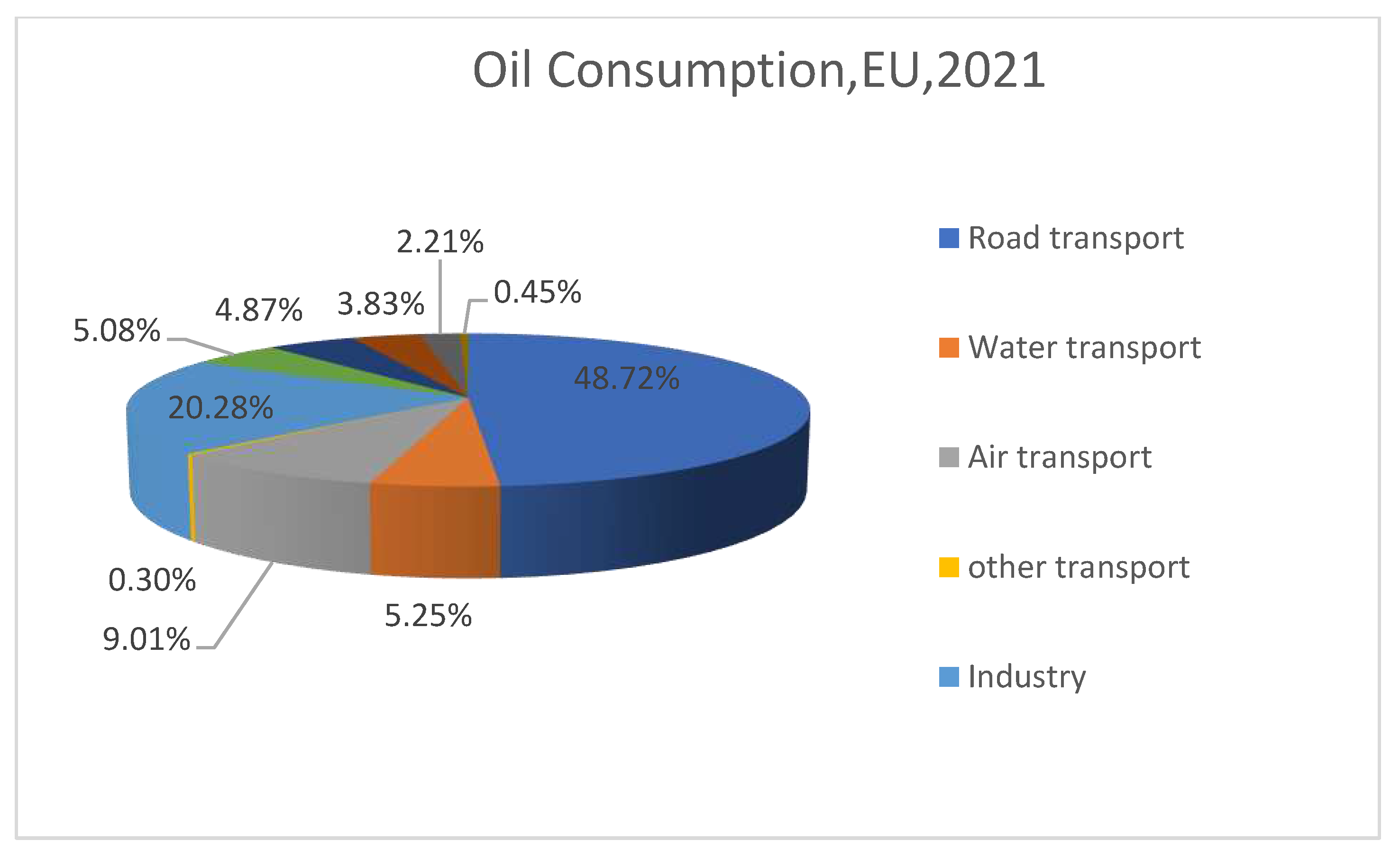
Figure 2.
Carbon dioxide emission data across diverse sectors.
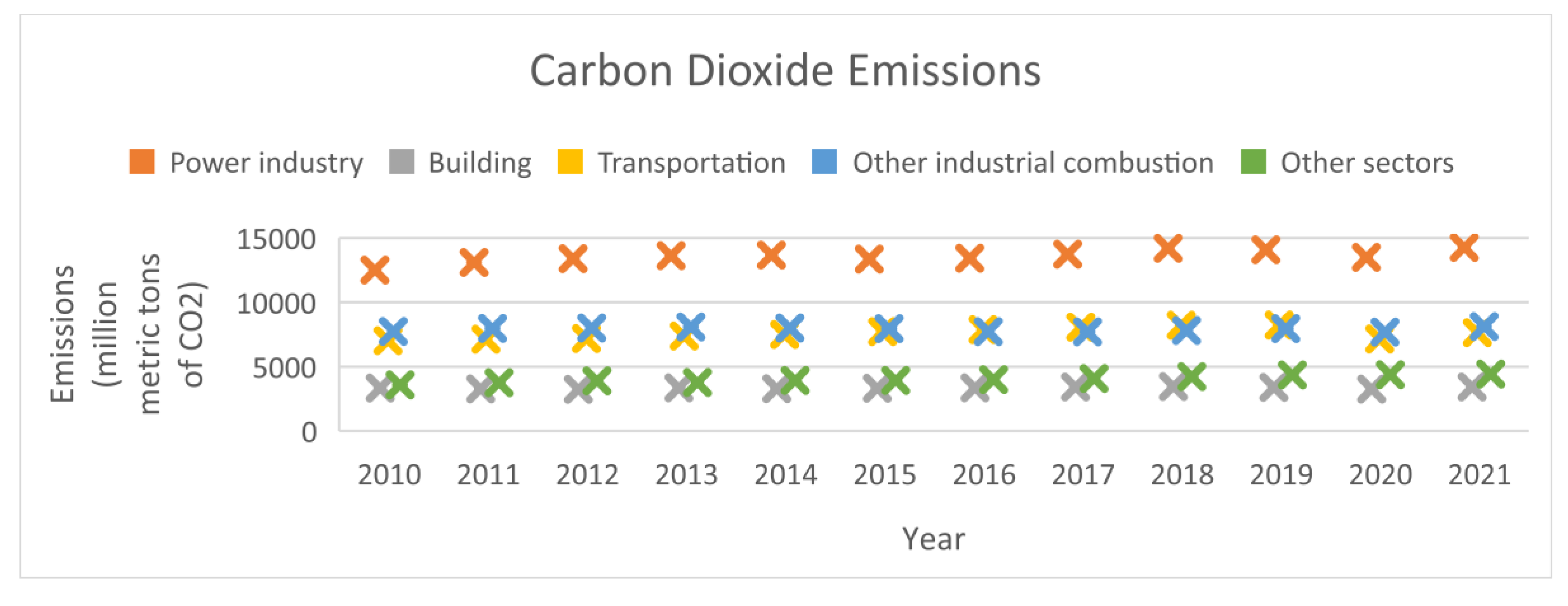
Figure 3.
The classification of vehicle.
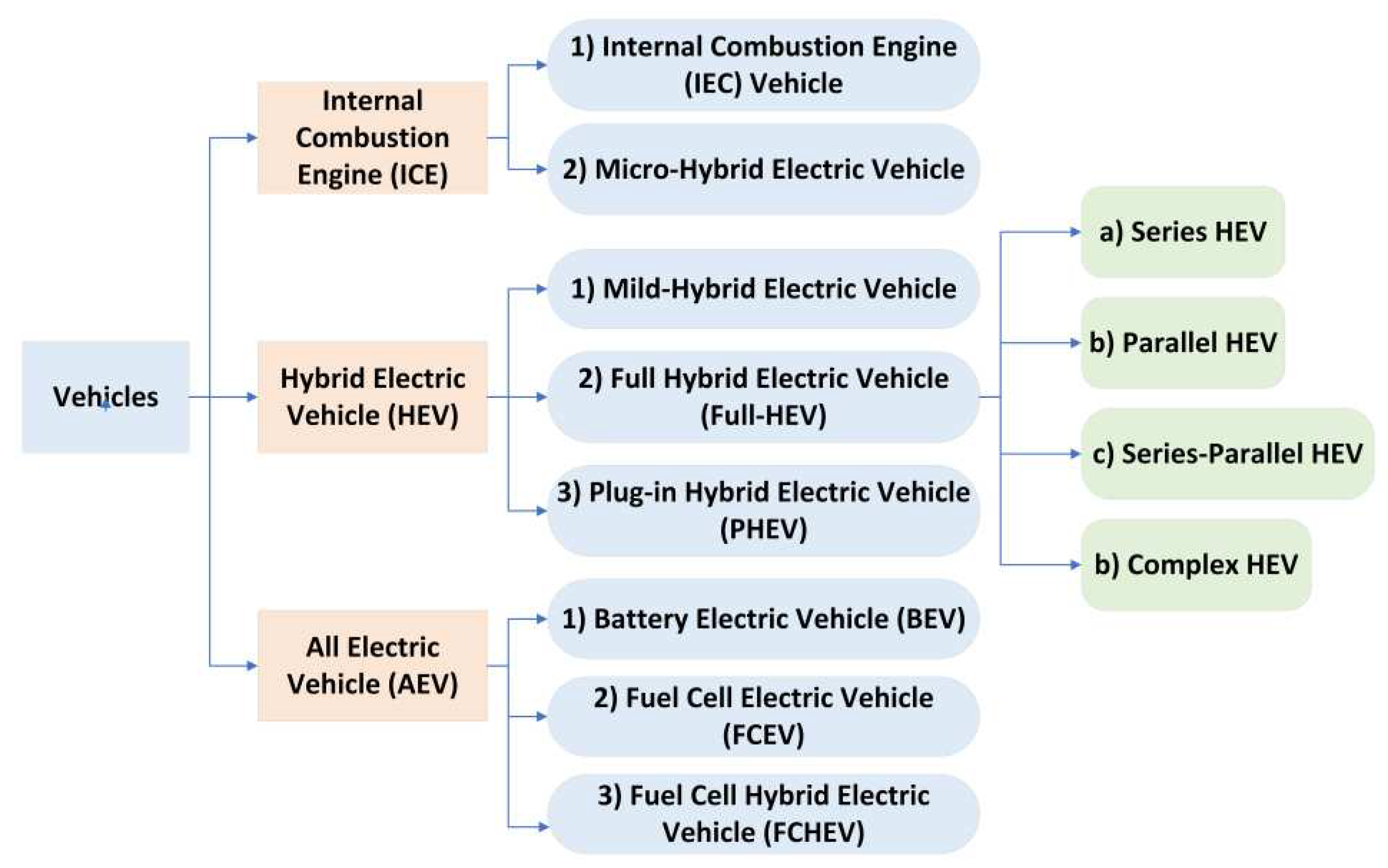
Figure 4.
Series-parallel HEV configuration.
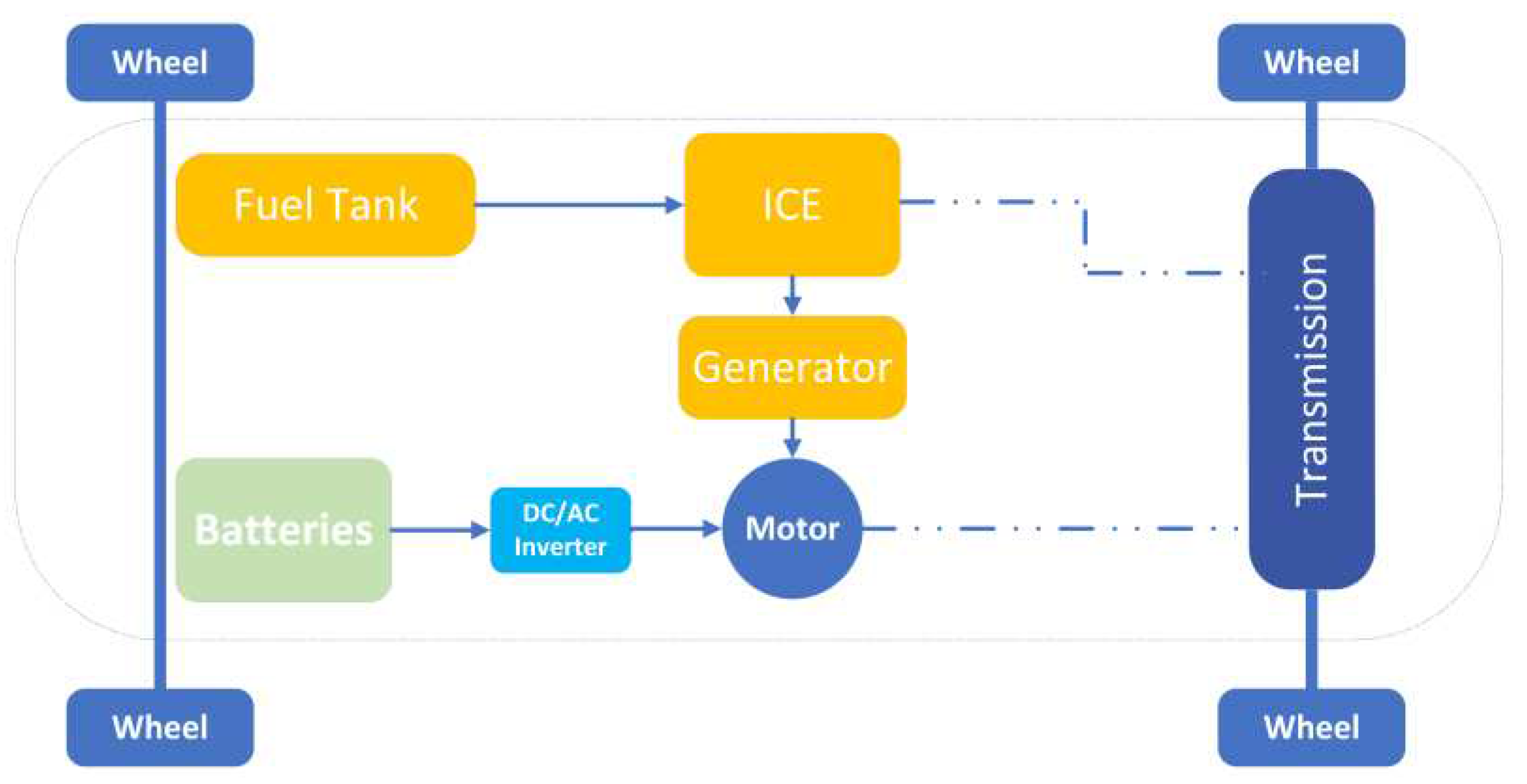
Figure 5.
FCEV configuration [27].
Figure 5.
FCEV configuration [27].
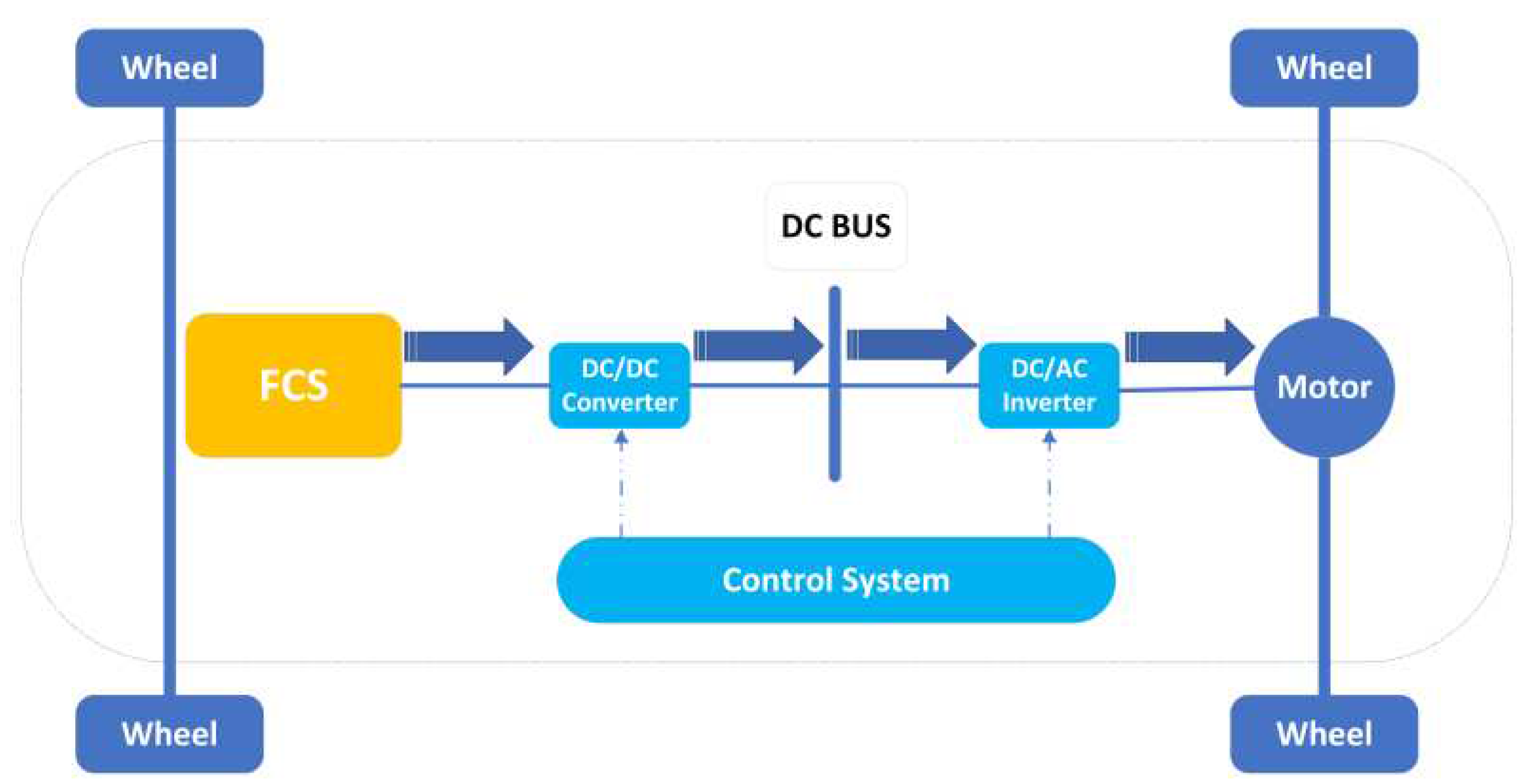
Figure 6.
FCHEV configuration [29].
Figure 6.
FCHEV configuration [29].
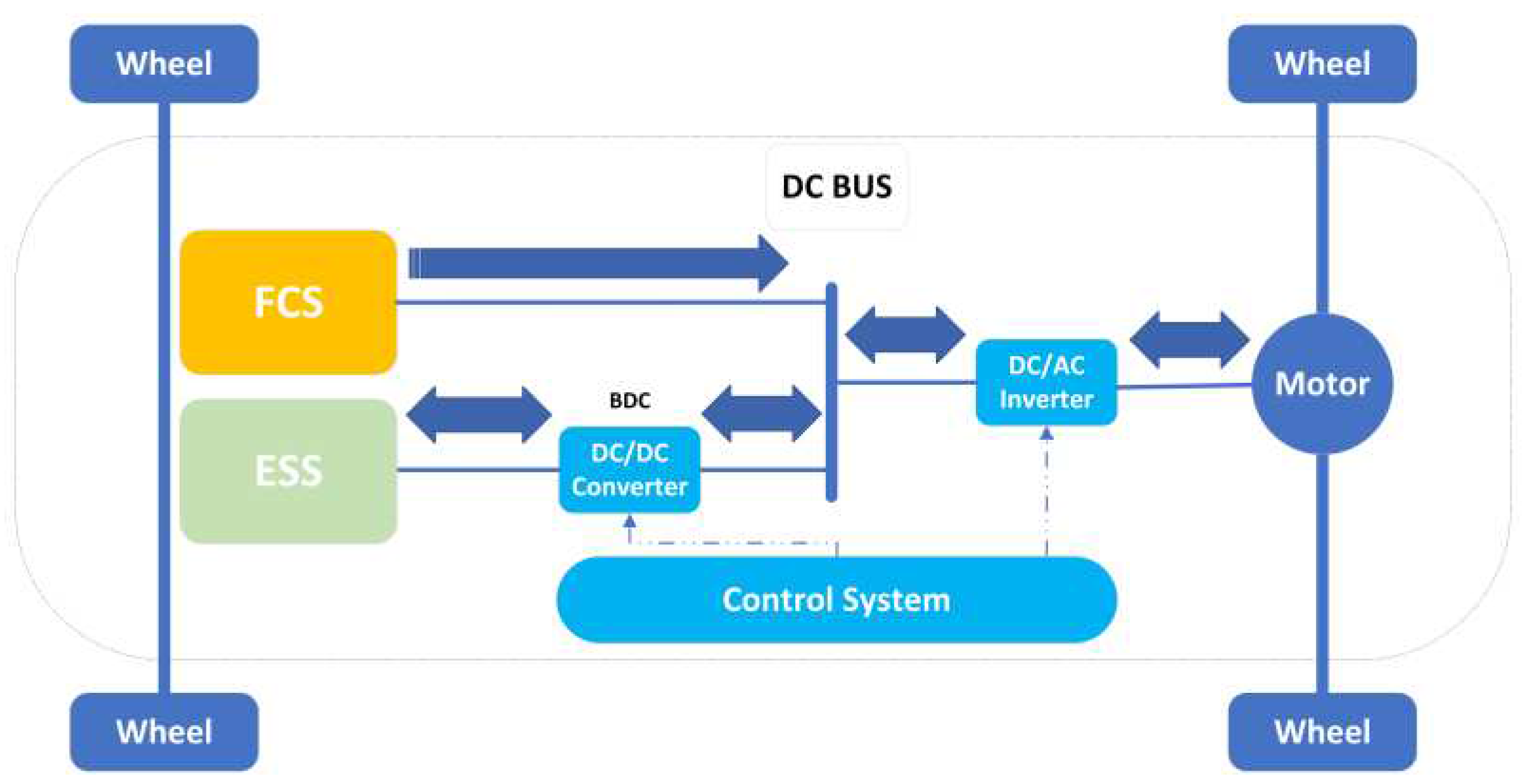
Figure 7.
FC and battery direct connection.
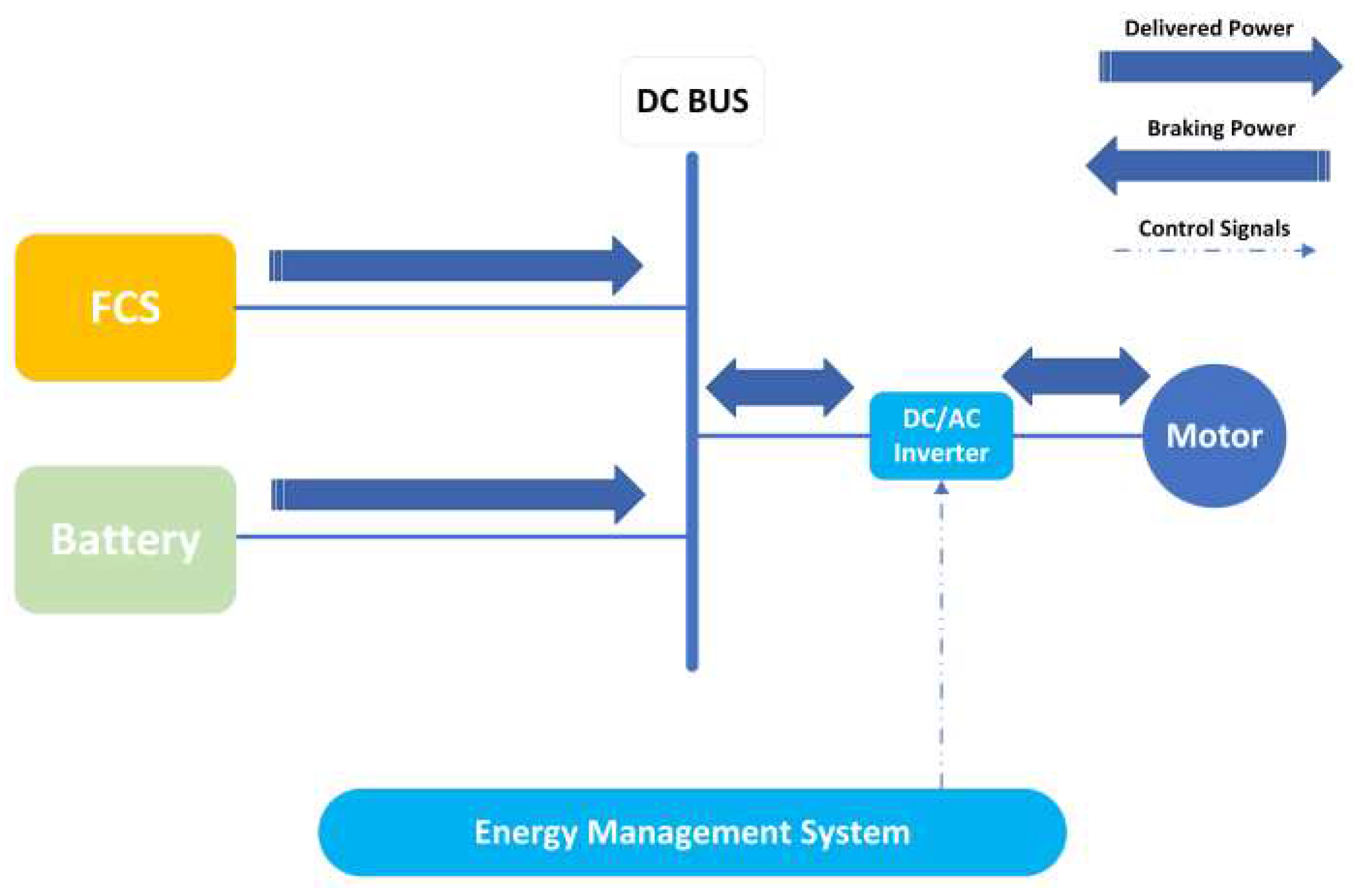
Figure 8.
FC direct connection.
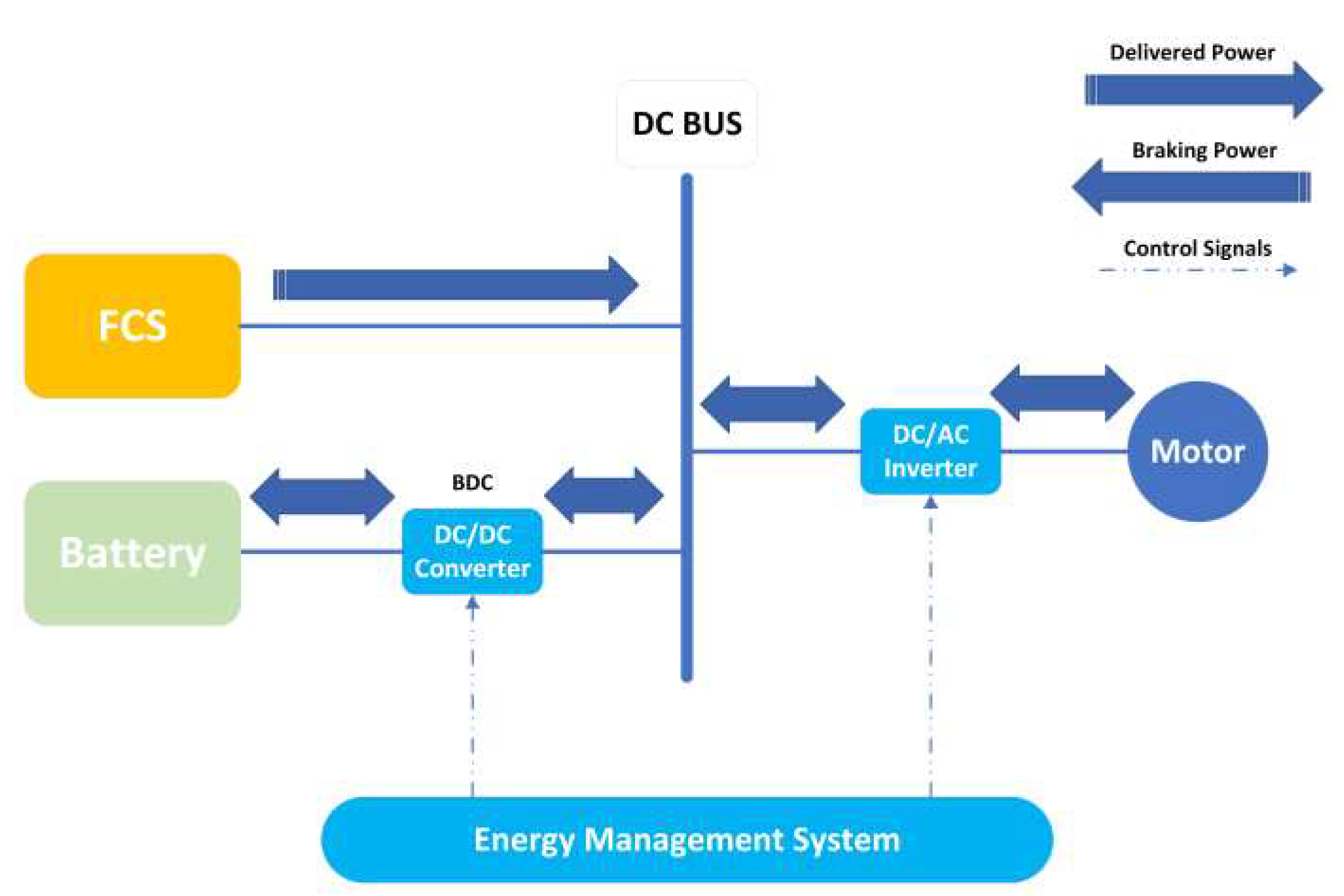
Figure 9.
Battery direct connection.
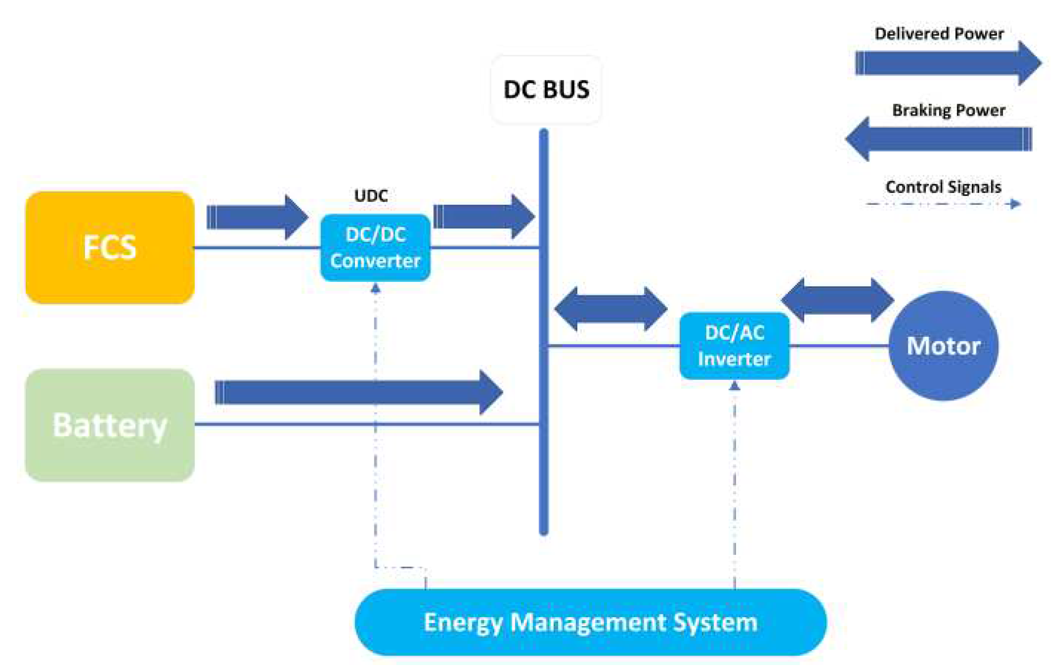
Figure 10.
FC and battery indirect connection.
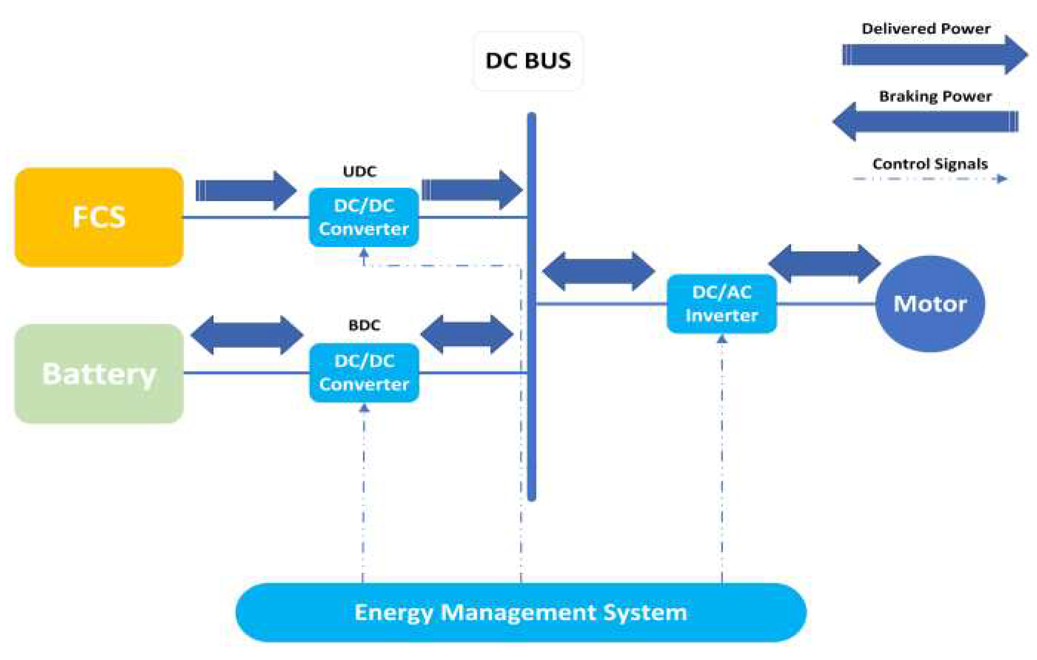
Figure 11.
(a). Battery and FC direct connection; (b). UC direct connection; (c). Battery direct connection.
Figure 11.
(a). Battery and FC direct connection; (b). UC direct connection; (c). Battery direct connection.
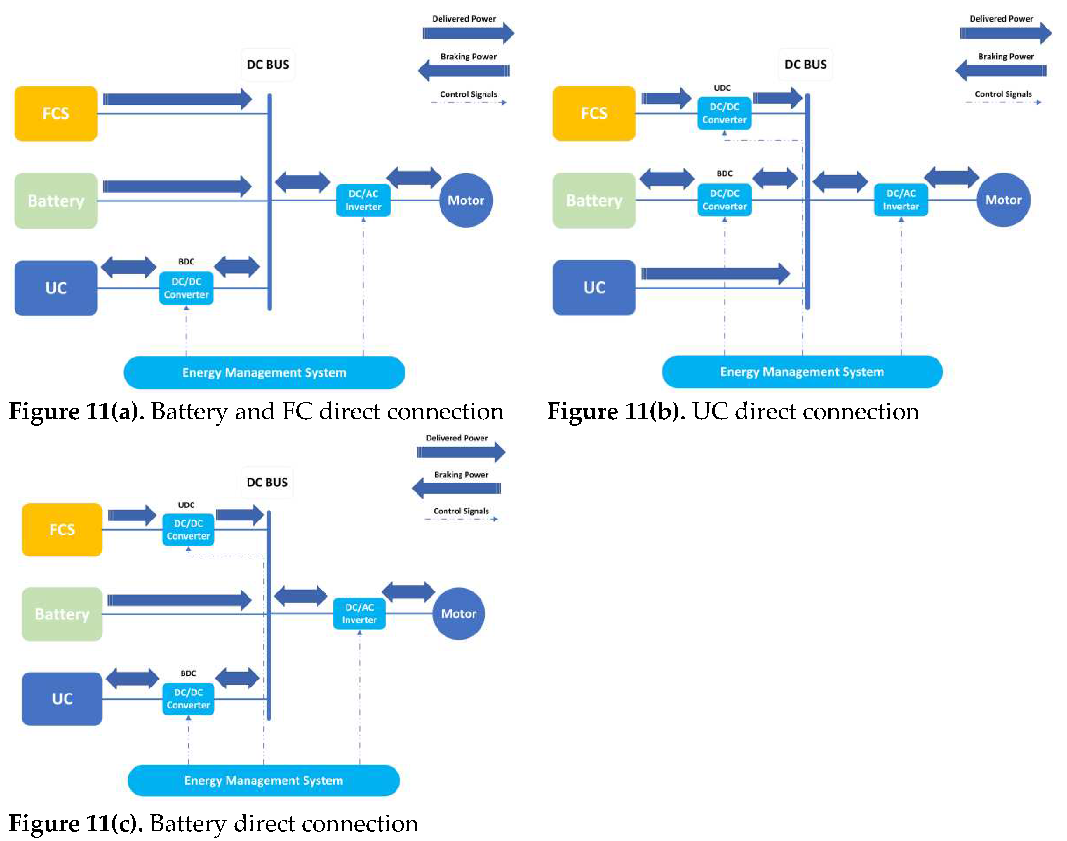
Figure 12.
Wirelessly charging of FC-battery-UC based HEV.
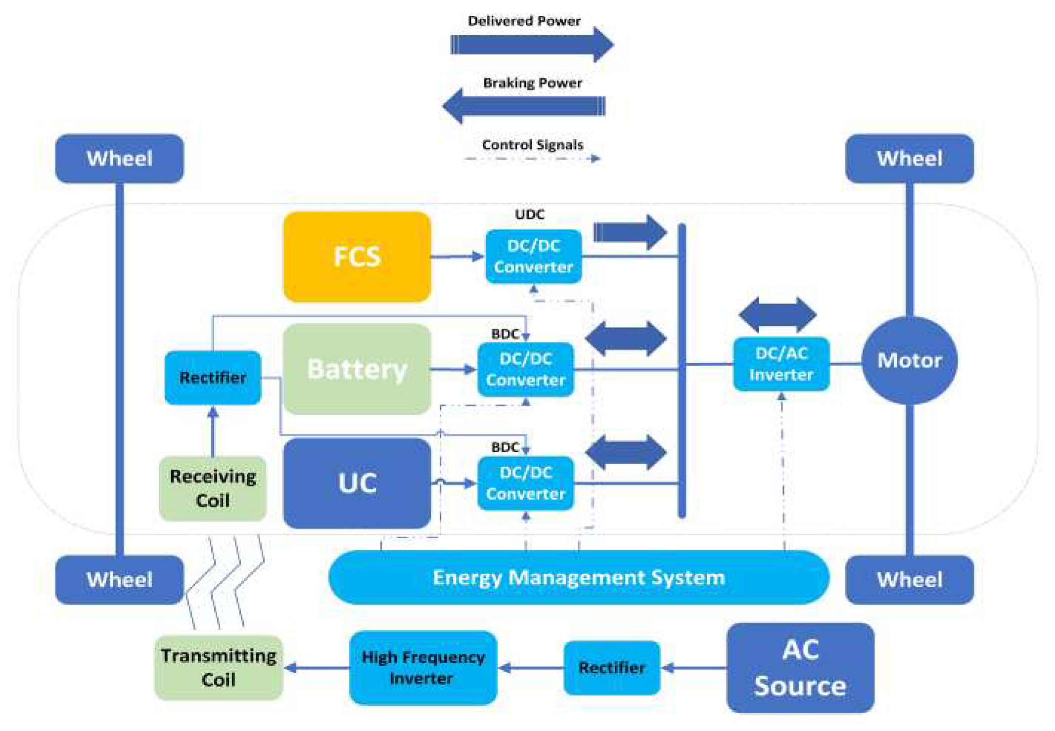
Figure 13.
UDC with isolation transformer.
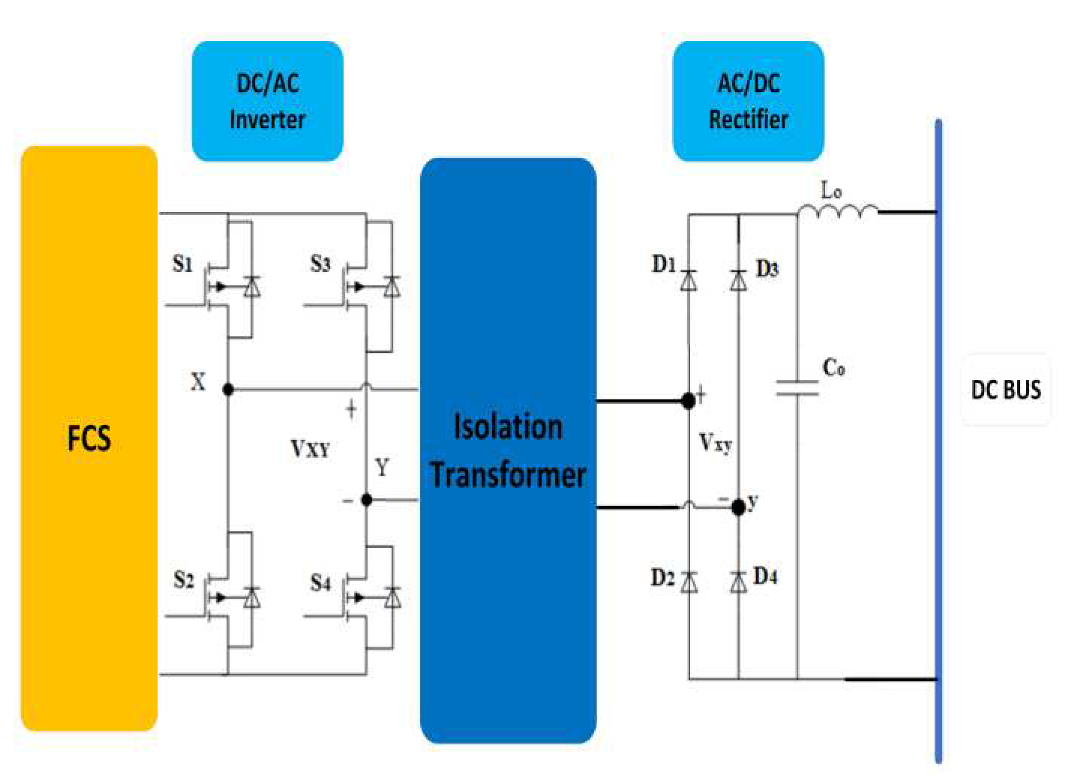
Figure 14.
FC-battery dual inverter system.
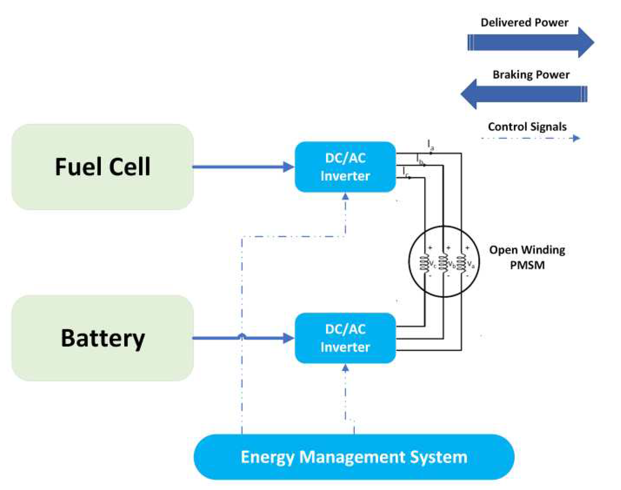
Figure 15.
FCHEV EMS Classification.
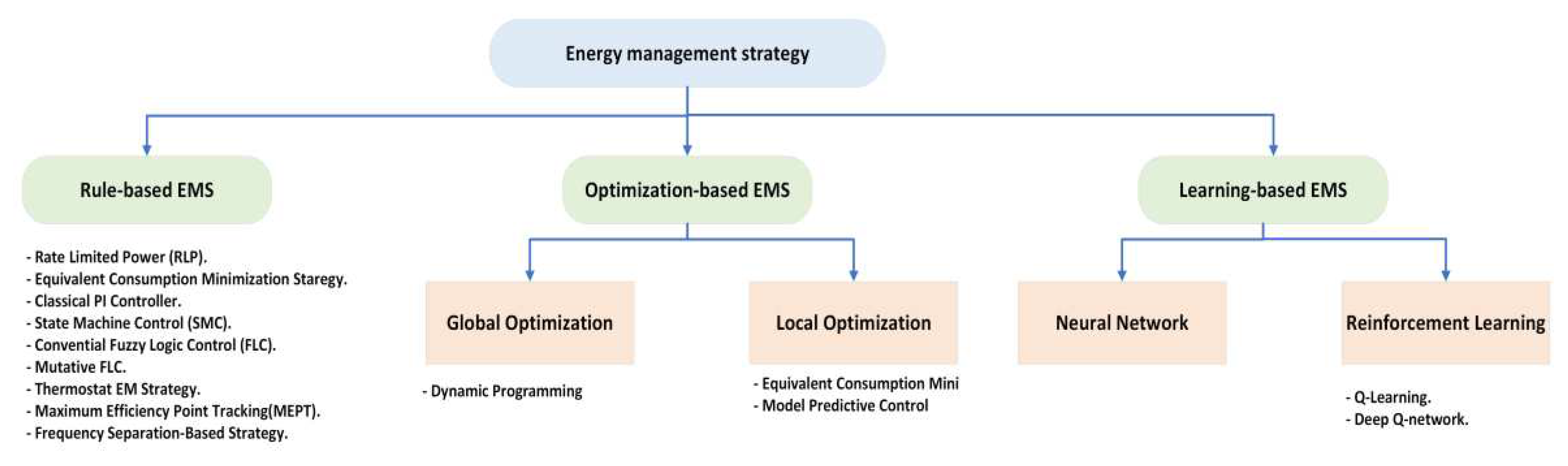
Figure 16.
Energy Management systems: Rate Limited Power, Equivalent Consumption Minimization Strategy (ECMS), PI Control, State Machine Control (SMC), and Fuzzy Logic Control (FLC) [77].
Figure 16.
Energy Management systems: Rate Limited Power, Equivalent Consumption Minimization Strategy (ECMS), PI Control, State Machine Control (SMC), and Fuzzy Logic Control (FLC) [77].
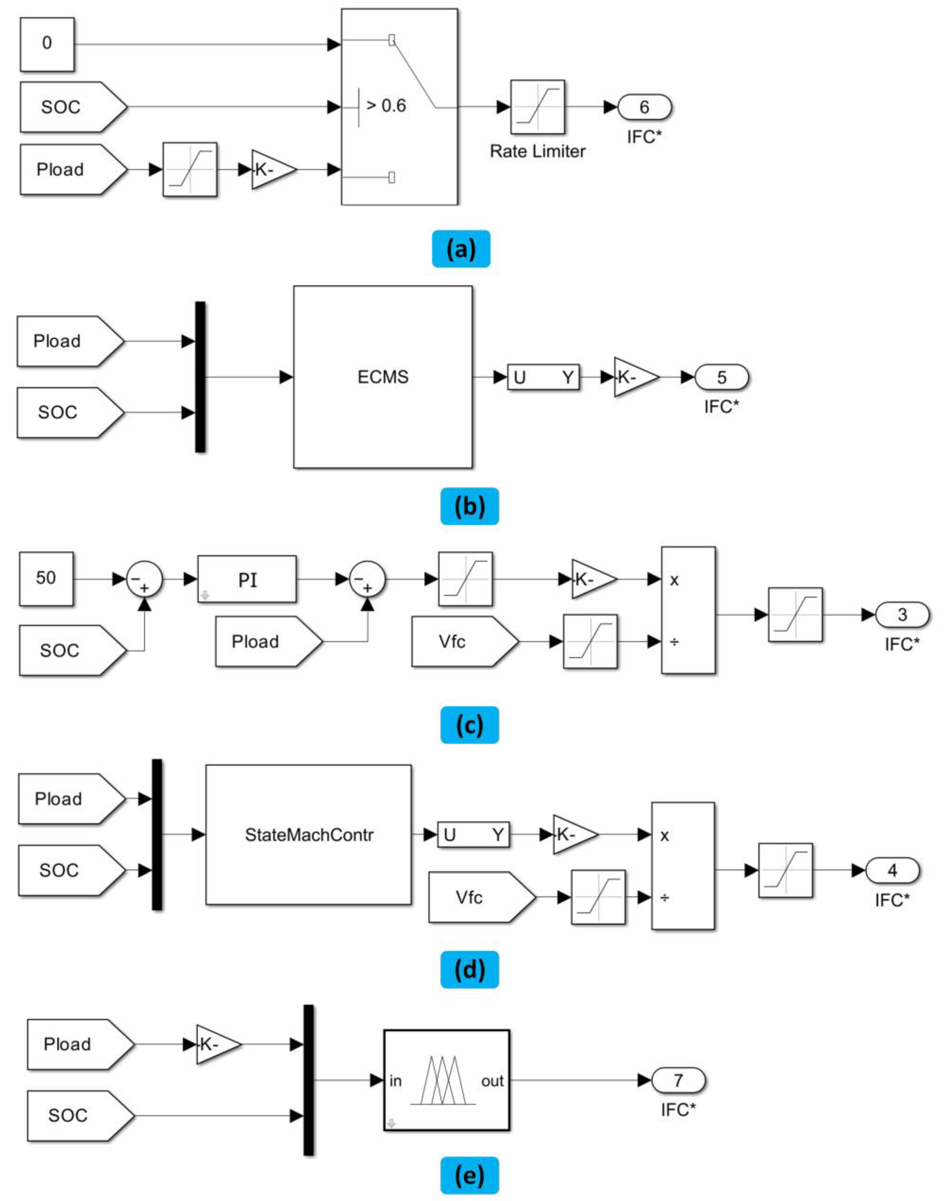
Figure 17.
Thermostat Energy Management Strategy.
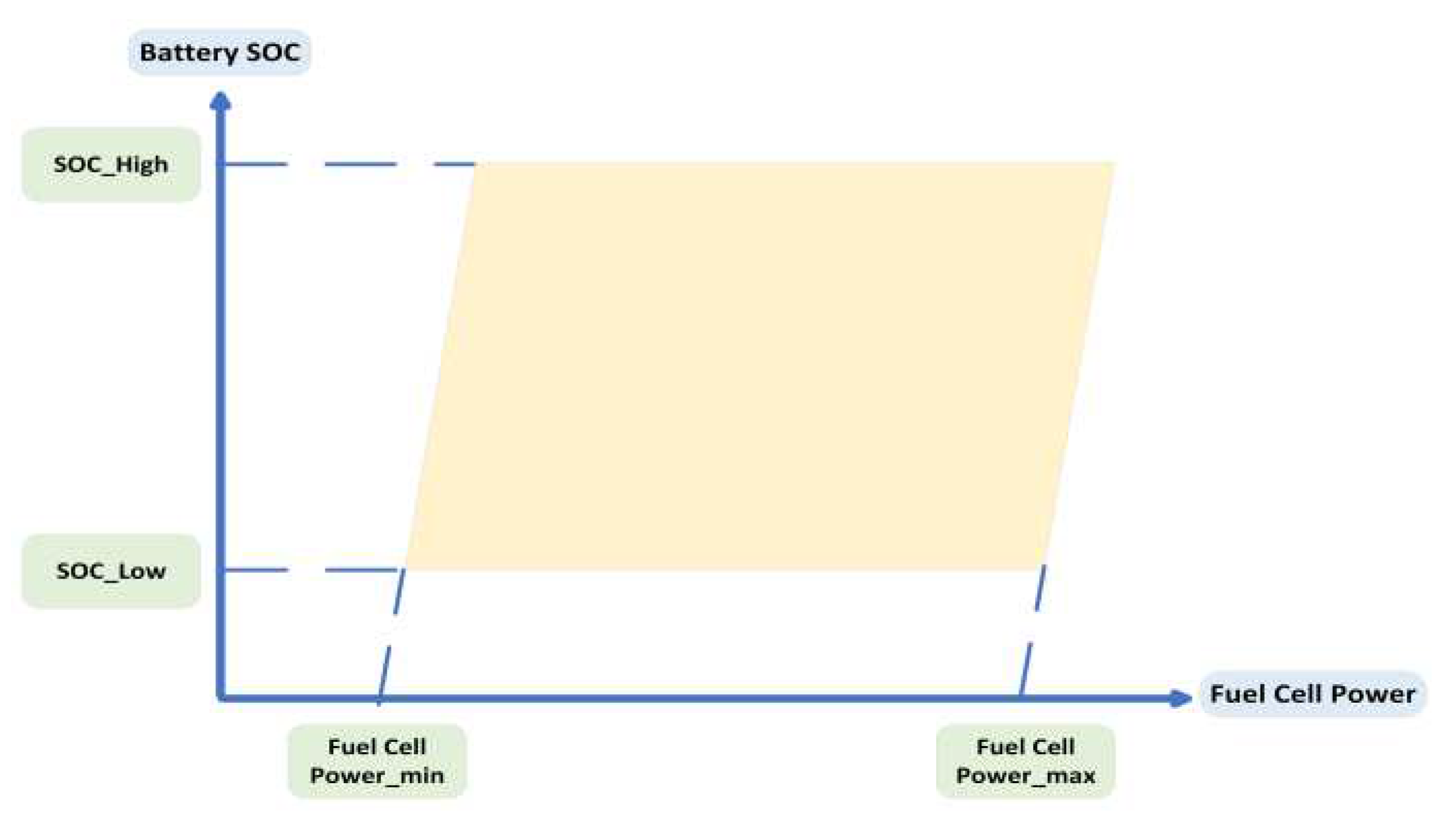
Figure 18.
Efficiency curve of PEMFC system.
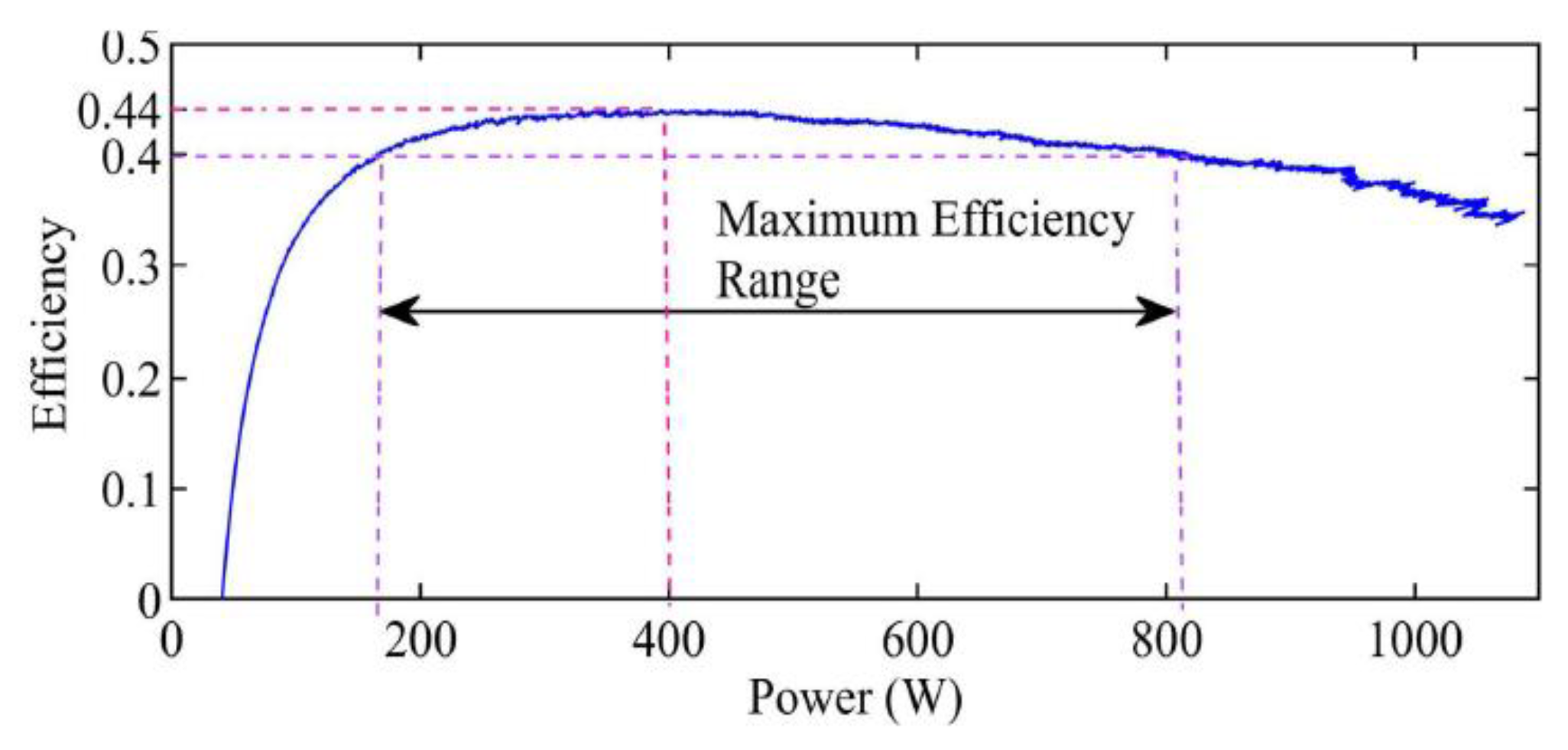
Figure 19.
EMS based on frequency separation.
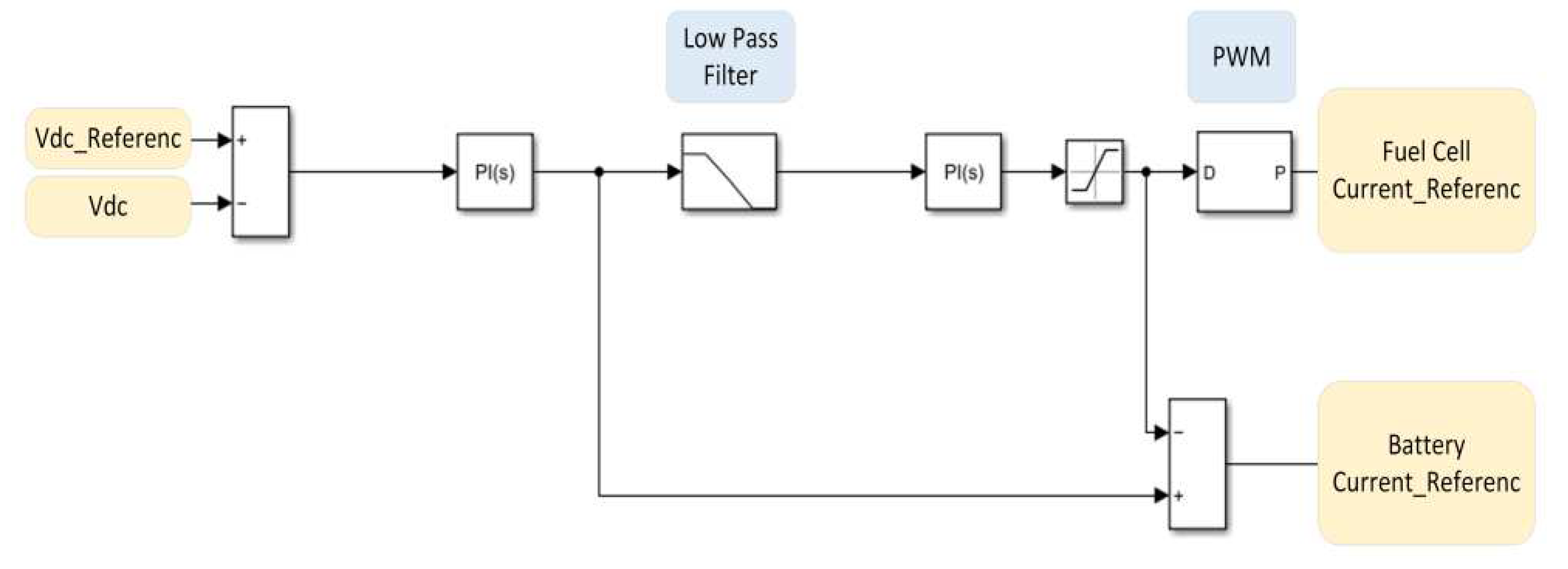
Figure 20.
(a) Offline optimization flow chart. (b) Operating condition identification schematic diagram.
Figure 20.
(a) Offline optimization flow chart. (b) Operating condition identification schematic diagram.
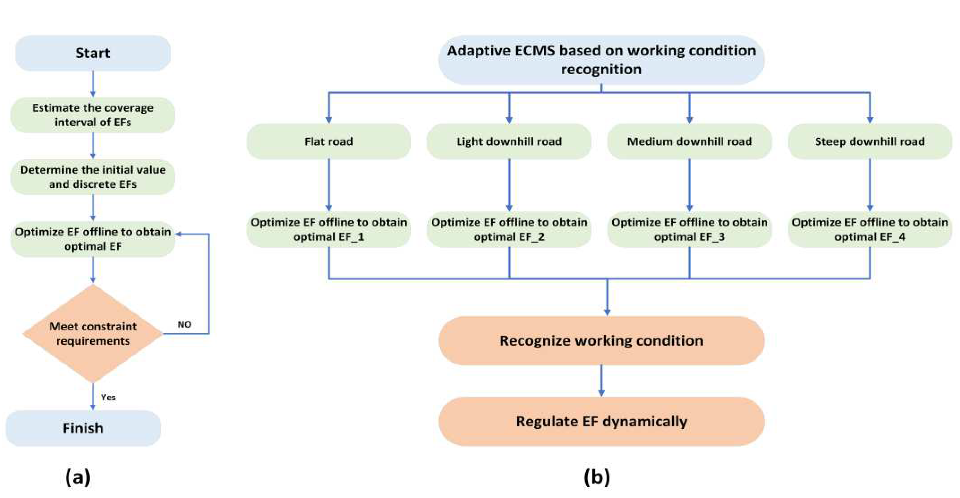
Figure 21.
Predictive control schematic diagram.

Figure 22.
Reinforcement learning schematic diagram.
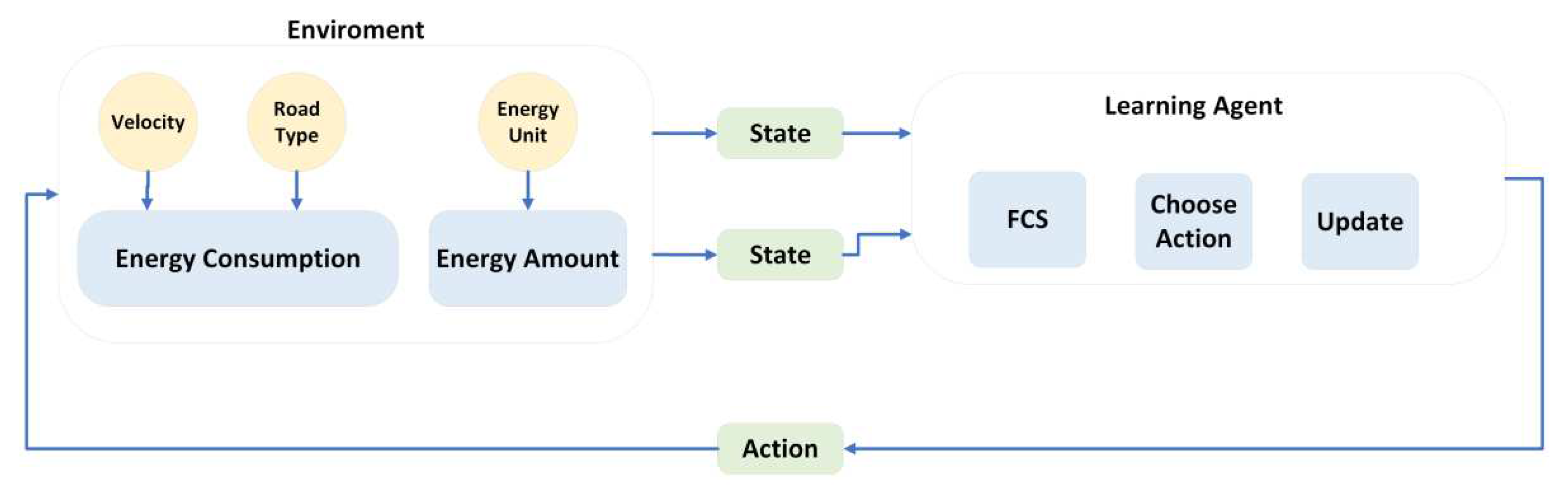
Figure 23.
Q-learning schematic diagram.

Figure 24.
DQN schematic diagram.
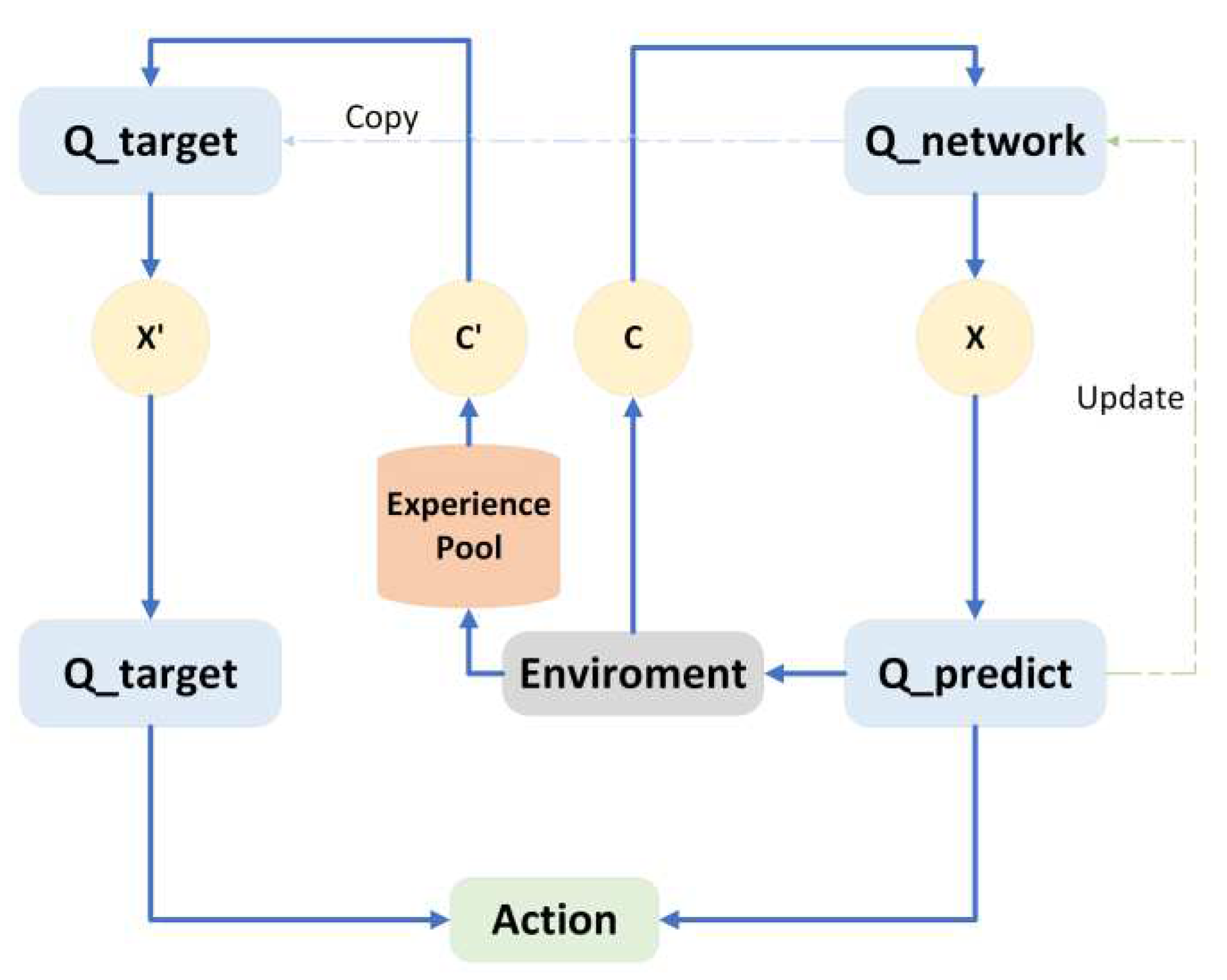

Table 1.
Pros and cons of various connection strategies of FCS + Battery hybridization setup.
| Type | Advantage | Disadvantage |
|---|---|---|
| Direct parallel connection of both FC and battery | Simple structure, well-organized arrangement, cost-effective solution and effortless implementation, absence DC/ DC converter drawbacks. | Component matching requirements, high voltage variation in the DC bus, complex management of each component's operational condition, low efficiency. |
| FC direct connection | Uncomplicated structure, effortless implementation, battery voltage value not essentially and improvement of the battery's energy efficiency. | High voltage variation in the DC bus, lower total energy consumption, strict criteria for dynamic responsiveness and the FCS is stable. |
| Battery direct connection | A longer FCS lifespan, less voltage variation in the DC bus, less needed for transient response and stability, and improved FCS energy efficiency. | Lower total energy consumption, Urgent need for reliable and efficient battery performance. |
| Indirect connection of both FC and battery | Reduced component matching requirements for the FC and battery, stable DC bus voltage level, and simple management of each component's operational condition. | A bigger filter capacitor is necessary, higher cost, lower efficiency, and more complicated. |
Table 2.
Comparing the characteristics of various hybridization topologies and their corresponding models.
Table 2.
Comparing the characteristics of various hybridization topologies and their corresponding models.
| Type | Advantage | Disadvantage | Model |
|---|---|---|---|
| FCS + Battery | Manufacturing at a lower cost, less demanding performance specifications for FCs, and improved starting capabilities. | Inadequate for absorbing and discharging power over an extended period. | Hyundai, Nexo, Toyota Mira, Honda. |
| FCS + UC | Greater flexibility to handle peak power absorption and release with improved energy utilization. | Not well-suited for prolonged high-load operation, challenging to regulate current, with poor starting and stability performance. | Honda, FCX-V4 |
| FCS + Battery + UC | Continuous supply of energy and improving dynamic operation. | Complex energy management approach, costly production processes, and intricate design. | No data |
Table 3.
Comparing the State machine control status [76].
Table 3.
Comparing the State machine control status [76].
| State | SOC | Load power | FC power |
|---|---|---|---|
| 1 | High | < | |
| 2 | High | < < | |
| 3 | High | > | |
| 4 | Normal | < | |
| 5 | Normal | < < | |
| 6 | Normal | > | |
| 7 | Low | < | |
| 8 | Low | > |
Table 4.
FLC Rules {Positive (P), Negative (N), Low (L), Medium (M), High (H)} [77].
Table 4.
FLC Rules {Positive (P), Negative (N), Low (L), Medium (M), High (H)} [77].
| FC Power | Load power | ||||||
|---|---|---|---|---|---|---|---|
| NH | NM | NL | PL | PM | PH | ||
| SOC | L | L | L | H | H | H | H |
| M | L | L | L | M | M | H | |
| H | L | L | L | L | L | M | |
Table 5.
FCHEV Topology and EMS Research during Recent Decade.
| Reference No. | Year | Type of Topology | Type of EMS |
|---|---|---|---|
| [91] | 2014 | FCS + Battery + UC | DP |
| [95] | 2018 | FCS + Battery | DP |
| [111] | 2018 | FCS + Battery | TCS, NN |
| [78] | 2018 | FCS + Battery + UC | FLC |
| [112] | 2019 | FCS + Battery | NN |
| [105] | 2021 | FCS + Battery | Local Optimization ECMS |
| [113] | 2021 | FCS + Battery | MPC, NN |
| [114] | 2021 | FCS + Battery | NN, Q-learning |
| [123] | 2022 | FCS + Battery + UC | FLC, Q-learning |
| [122] | 2022 | FCS + Battery + UC | FLC, MPC |
Disclaimer/Publisher’s Note: The statements, opinions and data contained in all publications are solely those of the individual author(s) and contributor(s) and not of MDPI and/or the editor(s). MDPI and/or the editor(s) disclaim responsibility for any injury to people or property resulting from any ideas, methods, instructions or products referred to in the content. |
© 2023 by the authors. Licensee MDPI, Basel, Switzerland. This article is an open access article distributed under the terms and conditions of the Creative Commons Attribution (CC BY) license (http://creativecommons.org/licenses/by/4.0/).
Copyright: This open access article is published under a Creative Commons CC BY 4.0 license, which permit the free download, distribution, and reuse, provided that the author and preprint are cited in any reuse.


