Submitted:
07 October 2023
Posted:
09 October 2023
You are already at the latest version
Abstract
The fatigue delamination damage is one of the most important fatigue failure modes of laminated composite structures. However, the developments of the theoretical framework, mathematical/physical model and numerical simulation of fatigue delamination are still challenging issues, and there is a lack of systematic classification. This article reviews the experimental phenomena of the onset and propagation stage of delamination under fatigue loading, and summarizes the commonly used phenomenological models for laminated composite structures. The research methods, general modeling formulas and development prospects of the phenomenological models are presented in detail. In the light of the analysis of finite element model (FEM) for the laminated composite structures, a number of simulation methods of fatigue delamination crack propagation damage model are carefully classified. Furthermore, within the theoretical framework of strength theory model (SM), fracture mechanics model (FM), damage mechanics model (DM) and hybrid model (HM), the complete procedure, application, capability assessment, advantages and limitations of the models are also discussed in detail. Finally, several valuable suggestions are given for the research interests, and challenging technical problems that need to be overcome on the fatigue delamination prediction of laminated composite structures in the future.
Keywords:
Laminated structures
; fatigue delamination
; phenomenological model
; Paris law
; cohesive element
; numerical methods
1. Introduction
Composite materials have many advantages such as high specific strength and strong designability. With the development of preparation and detection technology of composite material, the application of composite materials on civil aircraft is widely used. The composite materials which are applied in B757 and B767 account for 4%, which is 11% in B777 and even 50% in B787. Furthermore, the percent of composite materials in A350 has amazingly reached at 52%. In pursuit of lightweight for aircraft, a trend using more and more advanced composite materials is formed. Thus, the application of composite materials has become one of the important indicators to measure the performance of aircrafts. Although composite materials have many advantages, there are also many problems which are required to be solved in the servicing process.
Delamination is one of the most important damage modes of laminated composite structures. Delamination is very dangerous because it is visually undetectable within the laminated structures. Once delamination occurs, the stiffness and strength of the structure will greatly degrade, especially in compression mode. While the composite laminated structures of aircraft are subjected to the complex fatigue loading conditions, the damage propagation process of fatigue delamination is very difficult to be detected and monitored. Moreover, the damage of fatigue delamination is irreversible, which often leads to a serious decline in the performance of components and even flight accidents. Therefore, the researches on initiation and propagation law [1,2], the failure mechanism [3,4] and the numerical simulation [5,6] of delamination under fatigue loads are the significant issues to the damage tolerance and durability design of composite laminated structures.
As we all know, Fiber Reinforced Plastic (FRP) is often stacked into laminates by different directions laminas which has a single fiber direction, so the mechanical properties of laminates can be flexibly designed. However, the failure mechanism and failure modes of laminated composite structures largely differ from those of the metal structures. When dealing with angle-ply laminates, the mismatch of elastic modulus between the adjacent layers can result in the interlaminar stresses at the free edge of laminates. Furthermore, the interlaminar performance of FRP composite laminates is relatively weak, so that the larger interlaminar stress may lead to the failure mode of delamination. Even on the low stress level, it will cause fatigue delamination damage (FDD) as the performance of the interlaminar material degrades. In addition, the problem of FDD is more serious and critical in engineering structures with openings. Therefore, it is desirable to find a universal model of fatigue delamination damage for different composite laminated structures, which can simply and efficiently evaluate span fatigue life of delamination.
By reviewing a large number of literatures, the fatigue delamination damage model (FDDM) of the composite laminated structures can be divided into the strength model based on stress/strain field analysis [7,8], the fracture mechanics model [9,10], the damage mechanics model [11,12,13] and the hybrid model [14,15,16,17] according to the theory framework. In general, the performance of the FDDM can be verified according to the results of experiment including the double cantilever beam (DCB), the single lap joint (SLJ), the free-edge delamination and so on. At present, the Paris law [18] in metals based on fracture mechanics is commonly used to characterize the fatigue delamination growth (FDG) in the FDDM of composite materials. Furthermore, the phenomenological model is also established by utilizing the data from experiments. Considering about the complexity of composite laminated structures and loading conditions, various ways have been used to create and express a phenomenological model. Based on the influence factors of fatigue delamination failure, researchers have proposed a series of empirical and semi-empirical correction formulas [19,20,21], which provided methods of damage evolution for the simulation of FDDM. In recent years, the physical model, cohesive element based on damage mechanics [14,22,23] has received extensive attention and research. The cohesive element possesses the simple principle and high efficiency in numerical calculation, which greatly reduces the difficulty in simulation of FDG. In addition, some models in conjunction with the strength criterion with the fatigue progressive damage theory [24] have also been applied to estimate damage evolution of fatigue delamination, which shows a good agreement with experiments. Furthermore, investigators have already studied different hybrid frameworks of theories. A lot of valuable explorations have been made in the FDDM. The performances of these models have been verified through experiments and numerical simulations, and some practical conclusions have been also obtained. However, there are a number of problems without breakthrough.
Therefore, this article is to be divided into 5 sections. Section 2 introduces the characterization methods and significant influence factors of fatigue delamination. In Section 3, the general formula and procedure of the typical phenomenological models are summarized, including delamination onset and delamination propagation under fatigue loadings. Based on the framework of theories, Section 4 classifies the existing numerical simulations of fatigue delamination. Furthermore, the procedure, application and limitations of various FDDM have been compared in details. Finally, Section 5 sums up the up-to-date development of the FDDM, and gives suggestions on the research trends of the fatigue delamination and technical challenges.
2. Experiment and Mechanism of Fatigue Delamination
In order to investigate the delamination of composite laminated structures under fatigue loadings, many researchers have carried out numerous experimental studies based on the quasi-static delamination. In order to quantitatively characterize the damage of fatigue delamination, the relationship between the crack growth rate da/dN and the fatigue loading is established by combining the fatigue crack growth of metal with the experimental phenomenon of fatigue delamination. However, due to various of parameters and expressions of fatigue loadings, it is necessary to make a profound investigation of the influence factors on the crack propagation of fatigue delamination. In conclusion, researches on the experimental phenomenon and delamination mechanism of composite laminated structures under fatigue loadings have laid the foundation of the subsequent phenomenological model based on the experiment.
2.1. Delamination Test
According to the deformation characteristics of crack tip, the delamination crack growth of composite laminated structures can be divided into the open mode (mode I), the sliding mode (mode II) and the tearing mode (mode III) under the framework of fracture mechanics, as are shown in Figure 1.
2.1.1. Pure Mode Delamination Test
In order to obtain the fracture toughness of mode I [25] delamination propagation, ASTM specially formulated DCB test [26], with respect to unidirectional FRP composite laminates, as shown in Figure 2 (a). Because of the simple procedure, intuitive methods and fewer interference, DCB test is one of the most commonly used tests for researchers to verify the proposed FDDM.
Although ASTM has put forward a three-point bend end notched flexure (3ENF) test [27] for mode II, as shown in Figure 2 (b). Nevertheless, delamination crack growth is very unstable and the initial strain energy release rate (SERR) can only be obtained. Furthermore, the complete resistance curve (R-curve) cannot be obtained, which has significant impact on input parameters of the FDDM. Therefore, the test methods of mode II are still incomplete. In addition to 3ENF, other test methods such as the center notched flexure (CNF) [28], the over notched flexure (ONF) [29], the four-point bend end notched flexure (4ENF) [30] and the end load split (ELS) [31] also have different limitations. When verifying and analyzing the performance of the FDDM, it is required to select an appropriate test method.
There is no recognized standard experiment for mode III delamination test up to now. The experimental results obtained by edge crack torsion (ECT) [32] and split cantilever beam (SCB) [33] are sensitive to the geometric parameters of structures. In addition, the results are affected by mixed-mode of delamination, which result in incorrect measurement. Because the delamination test of mode III is still an open investigation subject, it is conservatively assumed that the delamination mechanism of mode III is similar to mode II. However, the fracture toughness of mode III is slightly higher than mode II.
2.1.2. Mixed-mode Delamination Test
In general, composite laminated structures are in a mixed-mode loading. Thus, the test methods of I/II mixed-mode delamination have been developed, including single leg bending (SLB) [34], fixed ratio mixed mode (FRMM) [35], cracked lap shear (CLS) [36], asymmetric double cantilever beam (ADCB) [37] and mixed-mode bending (MMB) [38]. It requires to be noted that the specimen form of MMB is the same as DCB and 3ENF. Moreover, MMB has developed a specific analytical solution, Therefore, it is included in ASTM [39], as shown in Figure 3.
2.1.3. Other Delamination Test
In engineering, the stacking sequence and ply orientation of composite laminated structures are complex. Thus, researchers often carry out fatigue delamination tests on the following specific composite laminated structures in order to verify the universality of FDDM. Firstly, fatigue delamination tests are studied by using the single-lap joints (SLJ) [40], the double-lapped joint (DLJ) [41] and the inclined and wedge joint. Second, fatigue delamination test of open-hole composite laminated structures [42] with different diameters and locations is also explored. Third, fatigue delamination test for angle-ply composite laminates [43] is further investigated. Figure 4 shows the finite element model of these three types of laminated structures, which are finished independently by authors.
2.2. Characterization for Fatigue Delamination
Based on the above tests, the delamination mechanism of composite laminated structures is gradually revealed. By summarizing the experimental phenomena, the researchers have obtained the characterization methods for fatigue delamination of FRP, which is similar to fatigue crack growth of metal. However, the preparation process of composite laminated structures is complex and different from metal. Furthermore, various initial damage modes such as voids, wrinkles and delamination are unavoidable. Composite laminated structures have not the stage of nucleation of cracks which is different from that of metal cracks. Therefore, the review article focuses on the description of experimental phenomena. Moreover, it is significant to characterize fatigue delamination onset and propagation of composite laminated structures under fatigue loads.
2.2.1. Fatigue Delamination Onset
First of all, considering the mode I fatigue delamination onset of FRP composites [44]. The onset of crack growth is determined by monitoring crack tip or flexibility of DCB specimens. The purpose of the test is to relate the maximum SERR GImax to the cycle of fatigue delamination onset Nonset . What’s more, G-N curve which is similar to S-N curve commonly used in fatigue of metal can be established. The critical fracture toughness GIC is equivalent to the static strength σs , and the fatigue SERR threshold Gth is equivalent to the fatigue strength limit σf . A typical fatigue delamination growth onset curve [44] can be obtained as shown in Figure 5.
2.2.2. Fatigue Delamination Propagation
During the test of FDG, the length of delamination a and cycle of loading N are under a whole-process monitor. The data of experiment is utilized to fitting the relationship between the crack growth rate and the fatigue load range. Furthermore, the expression of fatigue delamination propagation adopts the general formula of classical Paris law like Eq.(1). Therefore, the typical curve of normalized fatigue delamination crack growth (da/dN-∆K/Kc) [18] is shown in Figure 6.
Same as fatigue delamination onset, the delamination of mode I is selected as an example. As shown in Figure 6, the fatigue crack growth rate develops from the high-rate region III to the low-rate region I, which is following the direction of arrow. As the cracks propagate along the fiber direction, the loading range of crack tip and the fatigue crack growth rate decrease gradually. It is noted that the loading range can be described by different parameters, such as the stress amplitude ∆σ, stress intensity factor (SIF) range ∆K and SERR range ∆G.
In medium-rate region II (Paris law region), the crack growth rate is linearly logarithmic with the loading range. Furthermore, propagation of crack stops when reaching the lower limit of fatigue delamination load range ∆Kth. The fatigue crack growth rate of FRP composites is measured according to ASTM standard of metal crack growth [45]. It is worth noting that the slope of fatigue crack growth rate curve of most FRP composites is much larger than that of most metals [46]. Therefore, it is indicated that little disturbance of load range can produce large errors in fatigue crack growth rate. In other words, the variation of fatigue crack growth rate is more sensitive than metals.
2.3. Influencing Factors of Fatigue Delamination
The relationship between fatigue crack growth rate and loading range is usually used to characterize the propagation of fatigue delamination. Thus, the parameters involved in loading range [47,48,49,50] and different forms of load range [51] may directly influence the FDG. These main influence factors include the mixed-mode ratio, the fiber bridging, the load ratio, the temperature, the humidity, the load sequence and the expression of f (K or G) in Eq.(1). What’s more, there are several secondary factors such as loading frequency and wave form.
2.3.1. Mixed-Mode Ratio
According to the definition of the mixed-mode ratio in terms of energy, the mixed-mode ratio is ϕ=GII/G (G=GI+GII). In general, GIIC is obviously greater than GIC in FRP composites. As shown in Figure 7 (a) and (c), ϕ ranges from 0 to 1 with the gradual transition from mode I to mode II. In addition, the fracture toughness of mixed-mode evolves from GIC to GIIC. It can be found that upper limits of Gmax-N curves and log(da/dN)-log(Gmax) curves changed with different ϕ. However, lower limits of SERR remains unchanged. In other words, mixed-mode ratio directly affects the delamination onset and the fatigue crack growth rate [52]. Nevertheless, the influence of mixed-mode ratio can be ignored under low fatigue crack growth rate. These rules have been confirmed by investigation on experiment of Obrien [53].
In order to more accurately describe the relationship between delamination onset /fatigue crack growth rate and mixed-mode ratio, researchers [54,55] proposed a general curve fitting model based on a series of fatigue delamination tests of FRP composites. It is the most important that the fitting coefficient is a non-monotonic function of ϕ, which makes the tracking process of delamination onset and propagation more precise. As shown in Figure 7 (b) and (d), the change of maximum SERR Gmax and fatigue crack growth rate da/dN is divided into two stages. In the first stage, Gmax and da/dN monotonically change with the increase of mixed-mode ratio. In the second stage, Gmax and da/dN non-monotonically change along the arrow direction with the increase of mixed-mode ratio.
2.3.2. Fiber Bridging effect
In existing test standards, most test objects of fracture toughness and fatigue crack growth are unidirectional FRP composite laminates. The influence of fiber bridging [56] on the critical SERR GC is artificially introduced, which can obtain a complete R-curve [57,58]. From the initial stage of fiber bridging region [59], the critical SERR of delamination gradually increases and eventually tends to a stable value. Research of Zhang et al. [50] shows that the fiber bridging effect will lead to more complex characterization of delamination onset and propagation. It means that the lower limit Gth of curves will no longer be independent of the mixed-mode ratio.
As shown in Figure 8 (a) and (b), Yao et al. [60] carried out the test of mode I fatigue delamination and fitted curves of GIC and Gth with length of delamination. It can be found that fracture toughness of mode I GIC and lower limit SERR Gth can be constructed as piecewise functions of fatigue crack length a-a0. GIC and Gth gradually develop to a stable stage, which have a significant promotion when compared with the initial values. If the influence of fiber bridging is neglected, and the stable value of interlaminar parameters is taken for numerical simulation, it will lead to a conservative estimation of the fatigue delamination life of FRP composites.
2.3.3. Loading Ratio
When studying fatigue of metals, load ratio R has been always the focus of studies, and load ratio R has influence on the fatigue delamination of composite materials. If two of three loading parameters Gmax, Gmin and R are known, the form of fatigue loading can be determined. Therefore, while Gmax is fixed, the effect of load ratio on delamination onset and propagation is investigated. As shown in Figure 9 (a) and (c), the experimental study of Matsubara et al. [61] indicated that the higher load ratio is, the higher the lower limit of the delamination onset curve is, which increases the number of cycles of delamination onset. Meanwhile, the larger the average load is, the greater the slope of the delamination propagation curve is, which is increasing the fatigue crack growth rate’s sensitivity to disturbance of Gmax.
In order to simultaneously consider the effects of mixed-mode ratio and load ratio except fiber bridging, Allegri et al. [62] attempted to establish a relationship of coupling influence curve in form of Figure 9 (b) and (d). At the beginning of fatigue load, the higher the mixed-mode ratio, the greater the maximum SERR. With the evolution of fatigue delamination, the higher the loading ratio, the greater the maximum SERR under the same fatigue crack growth rate. Therefore, when considering the coupling effects of mixed- mode ratio and loading ratio, the contribution of both to fatigue delamination onset and propagation must be reasonably allocated. It is significant to obtain a phenomenological model matching through a series experiment.
2.3.4. Other Major Factors
Due to long-term service in hygrothermal conditions, the delamination resistance of composite laminates is weakened. The tests of Springer [63], Jin et al. [21] and Ramirez et al. [64] showed that the polymer matrix will be modified under high temperature and humidity especially for FRP composites. Therefore, matrix and inter-laminar properties of composite laminates will be directly affected. Hence, it is necessary to take temperature and humidity as parameters which influences the fatigue crack growth rate in special environments. Based on experiments, the quantitative expression of fatigue delamination behavior is obtained, with corresponding material system and loading cases.
There is no consensus on mechanism of the effect of fatigue load sequence on delamination propagation of composite laminates. On the basic of micromechanics, Li tried to study the interfacial fatigue debonding of unidirectional ceramic matrix composites under different loading sequences. In addition, Van Paepem and Degrieck [49] reviewed analytical methods of high-low fatigue load and low-high fatigue load of FRP composites. Thus, some issues and ideas about studying the influences of load sequence on fatigue delamination have been proposed.
When Paris Law is extended to composite materials, the problem of stress singularity at the crack tip is inevitable. Therefore, in the framework of linear elastic fracture mechanics (LEFM), the SERR G is established from the perspective of energy. In addition, the relationship between the SERR G and the SIF K is derived, which realize the substitution of load range. After fitting the data obtained from the test of fatigue crack growth rate, there are various function forms such as ∆G, Gmax, ,and so on [66,67,68], which have completely different intrinsic physical meanings.
2.3.4. Other Secondary Factors
In general, loading frequency [49,69] and loading rate [70] are secondary factors on strain energy release rate. As long as the frequency below 100Hz, the limitation of frequency ensures that high temperature will not locally occur in composite laminates, and fatigue crack growth rate will be not affected. The influence of load waveform is much smaller [69], so researchers rarely investigated on it.
3. Phenomenological Model of Fatigue Delamination
By Referring to section 2, the analytical method of fatigue delamination is established by qualitative analysis of observation phenomenon in experiments. Furthermore, the important factors affecting fatigue delamination onset and propagation are clarified. Therefore, calculation of SERR is briefly summarized in this section. Then, a number of phenomenological models are introduced from the different perspectives of influencing factor and data processing.
3.1. Calculation of SERR
Two methods are usually employed to solve SERR, which are analytical solutions and finite element method (FEM). For analytical solutions, please refer to the related standards of ASTM [26,27,39], which is including modified beam theory (MBT), modified compliance calibration (MCC) and so on. The area method can also be used to estimate SERR [71,72]. The FEM includes the virtual crack closure technique (VCCT), the J-integral method, the virtual crack extension and so on. Among them, VCCT and J-integral method are most widely used.
3.1.1. VCCT
VCCT has been rapidly developed since Rybicki and Kanninen [73] proposed it in 1977. The basic assumption of VCCT [74] is that the opening displacement of the virtual crack tip is approximately equal to that of the initial crack tip. In two-dimension (2D) finite element model shown in Figure 10, SERR of pure mode I and mode II of delamination are calculated by Eq.(2).
where, B is the crack thickness, ∆a is the crack length, Fx and Fy denote the force of node e and node f along the x and y directions respectively, ∆u and ∆v denote nodal displacement difference between the node c and node d along the x and y directions respectively.
However, the path of damage evolution of VCCT needs to be set up in advance. Unless the prefabricated laminated specimens which are used for testing, the path of delamination evolution cannot be determined in structures, much less to complex geometric characteristics and load conditions. Moreover, VCCT can only track the propagation of delamination but cannot predict onset of delamination.
3.1.2. J-Integral
In 1968, Rice and Rosengren [75] proposed the J-integral for 2D problems. The stress and displacement far-field solved by line integral, which are used to describe the mechanical properties of the crack tip. Since the phenomenological models involved in this review are all based on theoretical framework of LEFM, J-integral and SERR are completely equivalent for problems of plane stress or plane strain. Therefore, SERR can be easily calculated by line integral, which is independent with the path from the lower surface to the upper surface of the crack.
3.2. Delamination Onset Phenomenological Model
The simplest functional relationship like Eq.(3), which is based on Basquin formula to fit data from delamination onset test of FRP composites.
where m and A are fitting parameters, Nonset is the cycles of fatigue delamination onset at a certain loading level. However, the model does not consider the main influencing parameters such as mixed-mode ratio, loading ratio and temperature. Any change of structure, environment and load condition will result in different curve fitting results. Thus, easy formula like Eq.(3) has poor universality in practice.
Jagannahan et al. [76] introduced the concept of constant life diagram (CLD) which is commonly used in fatigue of metals. Furthermore, the constant onset life diagram (COLD) of mode II fatigue delamination of carbon fiber composite was established. After fitting the test data of three loading ratios R = 0, R = 0.5 and R = 1 (that is pure mode II) by Basquin formula, the curve between amplitude of SERR and the average SERR (Ga -Gm curve) was achieved. The COLD is obtained by connecting points of constant life. Then, cycles of fatigue delamination onset under the corresponding loading level can be obtained by linear interpolation.
However, the latest research on mode I and mode II fatigue delamination onset of carbon fiber reinforced polymer (CFRP) materials in hygrothermal conditions, Ramirez et al. [64] still adopted the model same as Eq.(3). It is obvious that there is no general model which can comprehensively consider influencing factors of fatigue delamination onset. There are few phenomenological models for fatigue delamination onset in composite materials, and there is a lack of experimental verification.
3.3. Delamination Propagation Phenomenological Model
Up to now, the phenomenological models of fatigue delamination propagation in composite materials are mostly based on classical Paris Law. According to the discussion on influencing factors of fatigue crack growth rate in Section 2.3, the existing modified Paris Law model is unified and summarized. The original formula of the modified Paris Law model is as follows Eq.(4).
3.3.1. Mixed-Mode Ratio Modified Model
For the Paris Law considering the mixed-mode ratio, SERR is generally used to characterize load level of composite materials. Thus, the similar parameters f (K or G) in Eq.(4) is simplified to f (G). When mode III is assumed equal to mode II, four issues need to be considered while establishing the mixed-mode ratio modified model.
Firstly, it needs to present the methods defining the contribution of different modes to fatigue crack growth rate in mixed-mode loading. Therefore, the uncoupled models [77,78] and coupled models [79] have been proposed. Secondly, it requires to determine the approach normalizing the load level [63,80]. Thirdly, coefficients of Paris Law may use the material constants or the functions of mixed-mode ratio. If the functions of mixed-mode ratio are adopted, the monotone [81,82] or the non-monotonic [19] function relationships have been presented. Fourthly, an approach introducing upper and lower limits [83] of fatigue crack growth rate to Paris Law model is also required.
From the simplest uncoupled models of mode I and mode II, modified Paris Law which considers uncoupled mixed-mode can be proposed by linear superposition. The general formula is given by
where, Ci and mi are material constants of mode i, f (Gi) are functions of loading levels. Different models can be obtained by changing forms of function. For example, the models of Gustafson and Hojo [78] can be obtained when f (Gi) = Gimax - Gimin. Nevertheless, the models of Ramkumar and Whitcomb [77] can be obtained when f (Gi) = Gi /Gic, which is normalized by critical SEER of mode i. Therefore, the fatigue crack growth rates of different FRP composites can be compared.
However, laminated composite structures under fatigue loading are usually in mixed mode. What’s more, the interaction between mode I and mode II/III in process of delamination propagation can’t be ignored. The simplest general interaction model between mode I and mode II is as follows.
When considering the general linear interaction,
It is observed that the essence of considering coupling effect of mode is to regard coefficients of Paris Law as a function of the mixed-mode ratio. However, C(ϕ) and m(ϕ) in Eq.(6) which is following the linear coupling relationship like Eq.(7) are monotone functions. For the epoxy matrix composite, it has been proved [80] that the coefficients of Paris Law are non-monotone functions of the mixed-mode ratio. Therefore, a non-monotone function can be constructed which needs to satisfy two conditions. Firstly, values of endpoint are equal to Paris Law coefficients of mode I and mode II respectively. Secondly, the stationary point of non-monotone function is within the range of 0 and 1. The quadratic function of ϕ can satisfy requirements by controlling boundary conditions.
The most general non-monotonic modified model including the effect of mixed-mode ratio is proposed by Blanco et al. [19]. The model is based on experimental observation in Section 2 and procedure of construction above.
As we all known, the classical Paris Law only describes middle-rate region of fatigue delamination. In order to simultaneously describe the thresholds of fatigue crack growth rate curve, it is possible to multiply Eq.(6) by functions which is representing lower and upper horizontal asymptote. The general formula of this kind of model is given by
where, the loading level G can be expressed in various forms and normalized or not. The multiplier gth(G) characterizes the lower horizontal asymptote of the fatigue crack growth rate curve. The value of function needs to satisfy two conditions. When load level is infinitely close to the fatigue crack growth threshold Gth, the value of function tends to be 0. When load level is slightly larger than the fatigue crack growth threshold Gth, the value of function tends to be 1. In a similar way, the multiplier hc(G) characterizes the upper horizontal asymptote of the fatigue crack growth rate curve. The value of function needs to satisfy two conditions. When load level is infinitely close to the critical fatigue crack growth Gc, the value of function tends to be positive infinite. When load level is slightly less than the critical fatigue crack growth Gc, the value of function tends to be 1.
Finally, the requirements of gth(G) and hc(G) are satisfied simultaneously. Therefore, the modified Paris Law which can describe the complete fatigue crack growth rate curve is obtained. The classical form of the function gth(G) and hc(G) can refer to the phenomenological model of Shivakumar et al. [83].
3.3.2. Fiber Bridge Modified Model
Based on the extensive application of unidirectional composite laminates in practice, the influence of the fiber bridge on fatigue crack growth rate can’t be neglected. By observing the phenomenological models which are considering the fiber bridge effect based on Paris Law, four issues need to be solved when establishing the model.
Firstly, it needs to select proper parameter which is similar to f (G). Secondly, the way considering the effect of fiber bridging by normalization is required. Thirdly, it requires to be determined that the coefficient of Paris Law is a material constant or a function of fatigue crack length. Fourthly, it needs to present a method which introduces the upper and lower threshold to fatigue crack growth curve. Based on the above considerations, the following general formula is given by
where c(a) and m(a) are coefficients of Paris Law which depend on the fatigue crack length. GCR(a) denotes the R-curve obtained from the fracture toughness experiment.
In the model of Shivakumar et al. [83], the definition of fatigue crack growth rate is simple. The function f = Gmax(a) / GCR(a), C and m denote the material constants. However, Gong et al. [68] have deduced the reasonable form of SERR by superposition principle from the concept of SERR. has a good agreement with the similar parameters ∆K in classical Paris Law. Yao et al. [66,67] elaborate on how to consider the effect of fiber bridge on mode I fatigue crack growth rate in a modified Paris Law. On the basis of above similar parameters, the Hartman-Schijve equation [60,84] and the idea of equivalent SERR at the crack tip [85] are used. Therefore, similar parameters which can consider the upper and lower threshold of fatigue crack growth curve and fiber bridge are respectively constructed by Eq.(11). These two phenomenological models based on modified Paris Law have been verified by various fatigue delamination tests. In addition, it is also concluded that the Paris Law coefficient m of mode I fatigue delamination is independent of fatigue crack length in FRP composite materials.
where ∆G(a), ∆Gth(a) and Gmax(a) are functions of SERR range, the fatigue crack growth threshold range and the maximum SERR which varies with the fatigue crack length a respectively. G0 denotes the initial SERR without fiber bridge effect. This model can well capture the fatigue crack growth rate at different fatigue crack lengths with high accuracy and simple fitting.
3.3.3. Loading Ratio Modified Model
The influence of loading ratio on fatigue delamination has always been a focus. From the analysis in Section 2.3, it is well known that as long as the combination of maximum and minimum loading levels such as Gmean, ∆G and Gmin/Gmax are involved in modified Paris Law, which is equal to consider the influence of loading ratio on the fatigue crack growth rate. Therefore, five issues need to be concentrated on when establishing a general model.
Firstly, it needs to select similar parameters in classical Paris Law. Secondly, the method of normalization is required to be determined. Thirdly, it is required to build the expression of loading level. Fourthly, the coefficient of Paris Law may use a material constant or the function of loading ratio. Finally, an approach introducing the upper and lower threshold of modified Paris Law is also required. Therefore, the general formula for developing such a model is as follows
where C(R) and m(R) are coefficients of Paris Law which depends on loading ratio. In simplified model, C and m can also represent material constants. f (Gmax, Gmin) denotes all combined expressions of maximum and minimum loading levels including normalized models. The simplest expression is ∆G = Gmax - Gmin.
Considering loading ratio in fatigue crack growth rate, the model proposed by Hojo et al. [47] is the most commonly used. The model represents the relative contribution of the SIF range ∆K and maximum SIF Kmax by parameter γ which ranges from 0 to 1. The construction of function f (Gmax, Gmin) is shown in Eq.(13).
In fact, after taking the logarithm on both sides of Eq.(13),
The kernel of constructing the function f (Gmax, Gmin) is the logarithmic weighted average of ∆K and Kmax. Actually, the concept is reflected in many classical modified Paris Law considering loading ratio. For instance, the expression of Eq.(15) was specially proposed for glass fiber reinforced laminated composites by Atodaria et al. [86].
However, the model mentioned can’t consider the effect of high and low rate regions of the fatigue crack growth curve. By directly incorporating the horizontal asymptote function into f (Gmax, Gmin) refer to the Eq.(9), the models of Shintarou et al. [87] considering the low rate regions and Blanco et al. [19] considering both the high and low rate regions are obtained. The specific functions are given as follows.
In fact, the model which is considering fiber bridging proposed by [60,85,88] also take the effect of loading ratio into account. In addition to replacing similar parameters with, the coefficient of Paris Law C (a, R) is set as a function of the fatigue crack length a and the loading ratio R. However, m(R) only depends on loading ratio R. By this way, the fatigue crack growth curves under different loading ratios are unified under the influence of fiber bridge.
3.3.4. Temperature Modified Model
As for the influence of hygrothermal conditions on fatigue crack growth rate, the influence of temperature is simply discussed here and the research of humidity can refer to temperature. Miura et al. [89] have studied I/III mixed mode fatigue crack growth curves of woven glass/epoxy composite laminates at 295K (room temperature), 77K and 4K. The results indicate that fatigue crack growth rates under three different temperatures satisfy da/dN295K > da/dN4K > da/dN77K. However, the modified Paris Law is primitive just like Eq.(17).
Above all, there is issue in similarity of ∆GT and ∆K. Secondly, the coefficient of Paris Law is not considered as a function of temperature. Therefore, not only accuracy and application of the model can’t be guaranteed, but also the influence of environmental temperature under same material system can’t be unified in a single fatigue crack growth curve. The model of Zhong et al. [90] also has similar defects.
In latest investigations, Jin et al. [21] measured the tensile-tensile fatigue crack growth rate of unidirectional and orthogonal Ti/CFRP Laminates at 25℃, 80℃, 120℃ and 150℃, respectively. The fatigue crack length nonlinearly increases with the increase of temperature. What’s more, acceleration of fatigue crack growth is obvious during the temperature difference from 120℃ to 150℃. Based on the concept of SIF, the general formula of modified Paris Law which is considering the effect of temperature is given by
According the experimental phenomena, the fitting functions which are satisfying requirement of nonlinear monotone behavior of C(T) and m(T) are as follows
where C0, C1, D0, m0, m1 and n0 are fitting parameters of experimental data. When material system and environment condition change, this kind of model with coefficient of Paris Law as the temperature function is very effective. The most important is that the reasonable fitting function should be adapted through observation of experiment.
3.3.5. Other Modified Models
With respect to influence of loading sequence on fatigue crack growth rate, investigators have different opinions because of the lack of experimental data about different material systems and loading conditions. Specific progress in this field can refer to references [49,65,69,91].
In terms of secondary factors, the FDM which considering the influences of loading frequency and loading waveform on fatigue crack growth rate can be reconstructed by Eq.(12)~(14). The term which is characterizing the effect of frequency and waveform can be directly added into expression of the model. Furthermore, the steps in details can be referred to relevant articles [92].
4. Finite Element Simulation of Delamination Fatigue
In this section, FDDMs are classified into four categories based on finite element model of fatigue delamination onset and propagation under fatigue loadings. In which, the framework of theories including strength model, fracture mechanics model, damage mechanics model and hybrid model. In order to comprehensively compare existing FDDMs, establishment process, application scope, prediction ability and limitation of various models are all taking into account.
4.1. Strength Model
Generally, the fatigue model of FRP composites can be classified into three types [93]: the model based on S-N curve, residual stiffness/strength model and progressive damage model. The similarity of these models is that they are based on classical strength theory and different forms of strength failure criterion. A similar method can be used to establish FDDMs of laminated composite structures.
In early stage, the methods of delamination simulation are mainly based on strength theory. After obtaining stresses field of laminated composite structures, the delamination damage is calculated by strength failure criterion expressed by stress components. Among macroscopic strength failure criterion of composites, criterions such as maximum stress, maximum strain, Tsai-Hill, Tsai-Wu and Hoffman are commonly used in engineering. For example, Bernasconi et al. [7] directly verified the correlation between the maximum shear stress and the number of failure cycles. Thus, τ-N curve which was obtained through SLJ test provided a simple and practical criterion for bonding structures.
However, these criteria are not able to consider failure mode of delamination alone. Hence, investigators have proposed microscopic strength failure criterion for delamination, such as Hashin criterion [94], Chang-change criterion [95], Hou criterion [96], Zou criterion [97] and LaRC criterion [98], which are shown in Table 1. These criteria are usually expressed by quadratic polynomials. Furthermore, the essence of criteria is transforming complex stress state into equivalent stress state. In many cases, in order to reduce the effect of stress singularity at crack tip, stress strength criteria are also rewritten as strain strength criteria.
While considering the influence of fatigue delamination in engineering, the maximum stress due to cyclic loading is usually less than 50% of ultimate strength of material. It is unreasonable that the structures without degradation of material properties never suffer from strength failure. Thus, material properties must be reduced in simulation of fatigue delamination. The residual stiffness/strength model and fatigue progressive damage model (FPDM) [99] are essentially models within the framework of damage mechanics for predicting fatigue delamination onset using strength theory. Furthermore, it will be elaborated in Section 4.3.
4.2. Fracture Mechanics Model
It should be emphasized that the fracture mechanics models are commonly based on framework of LEFM [100,101,102]. LEFM assumes that the complexity of the crack tip is not considered and the stress singularity of the crack tip is avoided. Instead, stress states of outer region of the crack tip are used to characterize the fracture behavior.
Compared with strength criterion, fracture mechanic model has developed a series of standard tests and formulas for solving the stress field at the crack tip under various crack forms. However, the unit of SIF K which is necessary for developing fracture criterion is [N][L]-2/3. The quantity lacks of explicit physical meaning. Thus, SERR G defined by Irwin [103] represents the energy consumption per unit area of crack growth and the unit is [N][L]-1. Through the strict proof of equivalence between G and K, fracture criterion can be automatically transformed into energy criterion. For instance, the relationship between SERR GI and SIF KI of mode I delamination is shown in Eq.(20). The loading levels can be characterized by SERR with more specific physical meaning in the process of fatigue crack growth. The main numerical computation method can refer to the brief introduction and references in Section 3.1.
In order to establish the relationship between fatigue crack growth rate and load level, almost all phenomenological models of fatigue delamination are based on the modified Paris Law. Based on the experiment, the influence of parameters and the methods of construction can refer to sections 2.2~2.3 and 3.2~3.3. The schematic diagram of FDM [104,105] based on Paris Law of fracture mechanics is shown in Figure 11. The steps in details are as follows.
- Artificial pre-cracks are added to laminated composite structures. Set the growth path of crack propagation and adapt displacement loading mode.
- When structure is applied cyclic loading, it is assumed that f (K or G) is constant during the increasement of fatigue crack length ∆a. The general Paris Law is converted into incremental form as shown in Eq.(21).
- 3.
- By means of VCCT or J-integral method in FEM, f (K or G)n near the crack tip of delamination in current increment step is calculated.
- 4.
- (∆N)n is acquired by substituting known coefficients of Paris Law C and m, ∆a and f (K or G)n which are obtained in previous step into Eq.(21). It should be noticed that C and m can be material constants or functions of parameters such as fatigue crack length a.
- 5.
- Update cycles of fatigue loading Nn+1 by Eq(22). The stiffness of structure declines because of delamination damage. Go back to step (2) and calculate delamination propagation of next incremental step until it stops when f (K or G) ≤ f (K or G)th. Record final fatigue crack length a and cycles of fatigue loading N. f (K or G)th is inherent properties of material which is obtained in test of fatigue crack growth rate.
Paris Law is directly applied to fatigue delamination in finite element software. The life prediction of laminated composite structures can be completed as long as the general formulas summarized in Section 3.3 are used to construct the modified Paris Law. In addition, various influence parameters mentioned before can be considered. Then, the data of material system are fitted by experiments.
However, the fracture mechanic model also has limitations [106]: (1) The essence of finite element is discretizing structure, and increment of fatigue crack length ∆a is usually equal to characteristic length of element Lc. The higher the mesh density is, the higher the accuracy of fatigue crack growth curve da/dN-∆G is. Therefore, the model is strongly sensitive to mesh size. (2) Coefficients of Paris Law are parameters of material properties. Thus, it is difficult to accurately simulate fatigue delamination at the interface of mixed materials. (3) The FEM needs the growth path of pre-crack in advance. What’s more, it is not able to predict onset of delamination and simulate the spatial cracking because there are no parameters in traditional Paris Law to determine the direction of delamination.
4.3. Damage Mechanics Model
The damage mechanics model [107] can directly predict delamination onset and propagation. Thus, compared with fracture mechanics model, it has been paid more attention in recent years. At present, numerical methods of fatigue delamination based on damage mechanics can be classified into three types: FDDMs based on degradation of intra-laminar element, FDDMs based on degradation of inter-laminar element and FDDMs based on degradation of hybrid intra-laminar element and inter-laminar element. Taking delamination of mode I as an example, the schematic diagrams are shown in Figure 12.
4.3.1. Intra-laminar Element Model
Based on degradation of intra-laminar element in FDDMs, stresses of intra-laminar element around the crack tip are substituted into strength criterion to estimate the delamination onset. Furthermore, delamination propagation is simulated by damage evolution. The concept and procedure of residual stiffness/strength model and FPDM are similar. Therefore, the specific analysis process of residual stiffness/strength model is given in Figure 13.
As the number of cycles increases, properties of the intra-laminar element gradually degrade [99]. Stiffness degradation leads to redistribution of stress fields. Furthermore, laminated composite structure achieves a higher stress state. Strength degradation changes parameters of strength in failure criterion. Therefore, local static strength failure occurs first in structure, and it finally leads to overall structural failure.
In addition to strength failure criterion of delamination, many investigators have studied degradation model of material parameter, damage variable [108,109,110] and damage stiffness matrix [111] on intra-laminar elements. Although intra-laminar element model can implement the simulation of delamination onset and propagation, the failure mechanism is essentially different from the interface of actual structures. Moreover, stiffness/strength degradation model depends on a large number of experiment data, which increases cost. Besides, the empirical assumptions of damage variable and constitutive model reduce the prediction accuracy of fatigue delamination.
4.3.2. Inter-laminar Element Model
The cohesive zone model (CZM) is the main method of FDDMs based on degradation of inter-laminar element. The history of CZM can be traced back to the D-B model [112,113] which is established by Dugdale and Barenblatt. CZM is essentially a phenomenological model. The traction-separation law of cohesive element is a phenomenological description of fracture process near the crack tip. CZM has simple constitutive equation and clear physical meaning. What’s more, it is easy to be realized in FEM software. Therefore, simulation of fatigue delamination based on cohesive elements has been rapidly developed. The basic procedures of inter-laminar element model under fatigue loading are as follows.
- (1)
- Derive the stiffness matrix and the constitutive equation (that is cohesive law) of cohesive element.
Camanho et al. proposed an interface element between solid elements, which can simulate onset and propagation of mixed-mode delamination. This element has been incorporated into ABAQUS software. The cohesive element established by Jiang et al. [114] considered the change of mixed-mode ratio during delamination propagation. What’s more, the numerical results are in good agreement with the experimental results. In terms of cohesive law, Needleman [115] proposed the exponential law, Tvergaard and Hutchinson [116] proposed the trapezoidal law, Mi et al. [117] proposed the bilinear law, Heidari-Rarani et al. [118] proposed the trilinear law. These constitutive relations are shown in Figure 14. However, relevant studies [119] have indicated that different forms of constitutive relations have no obvious effect on the load-displacement curve of laminated composite structures. The bilinear law has good computational efficiency, accuracy and convergence. Therefore, most of FDDMs based on cohesive elements generally use the simplest bilinear softening constitutive relations.
- (2)
- Determine the damage initiation and evolution criterion of mixed-mode fatigue delamination.
At present, the damage initiation criterions of delamination which are integrated in ABAQUS include the maximum principal stress/strain criterion, the maximum nominal stress/strain criterion and the quadratic nominal stress/strain criterion. The damage evolution criteria of delamination include Power law, B-K law [120] and Reeder law [121], in which Reeder law can automatically degenerate to Power law when GIIC=GIIIC [6]. Turon et al. [122] proposed a delamination initiation criterion which takes consideration about the effect of crack closure and satisfies the condition of thermodynamic consistency. By controlling the relationship between interface strength and stiffness, a method for accurately predicting the propagation of mixed-mode delamination has been developed [102]. The common criteria introduced above are summarized in Table 2.
Figure 15 shows the quadratic nominal stress criterion and B-K law of mixed-mode delamination which are the most commonly used. The black solid line derived from the arrow in Figure 15 is the envelope of damage initiation and evolution of cohesive element. Therefore, different damage initiation and evolution criteria of delamination should be constructed according to material systems. It is the guarantee of accurately tracking the damage initiation and critical fracture toughness under mixed-mode delamination.
- (3)
The patterns of inter-laminar properties degradation under fatigue loading are shown in Figure 16. It illustrates the difference between two kinds of model. It is necessary to calculate degraded parameters of each cycle in loading-unloading hysteresis damage model. This method is not desirable under high-cycle fatigue delamination because of extreme high computational cost. However, only the maximum value of load block is considered in envelope load damage model. It is assumed that the damage is continuous and average in each loading block [128], which is greatly improving the efficiency of simulation.
At present, most damage models which are based on CZM adopt the method of envelope load. Zhang et al. [129] proposed an explicit FEM for predicting the fatigue delamination of composite laminates by using twin cohesive models and a combined static and fatigue cohesive formulation. Compared with the traditional envelope load method, twin cohesive model is subjected to peak and valley envelope load respectively which means that the effect of loading ratio is considered in the model. At the same time, it is significant that the novel model improves the computational efficiency of fatigue delamination.
- (4)
- Establish the differential relationship between damage variables and the number of loading cycles. Furthermore, the reasonable formula of fatigue delamination damage rate can be obtained.
In situation of applying the envelope load method to simulate fatigue delamination, the total damage rate of delamination dD/dN is the sum of quasi-static damage rate dDs/dN and fatigue damage rate dDf /dN. Assuming that the current cycles of loading is N, the damage variable is updated by Eq.(23) after increment of loading cycles ∆N.
Generally, left rectangle formula [14,130,131] and trapezoid formula [132] are used to numerically integrate Eq.(23) to obtain the damage variable under current cycles of loading.
Robinson et al. [133] proposed a fatigue damage rate model with three parameters. The curves of fatigue crack growth rate obtained by simulation are consistent with the fitted Paris curves obtained from experiment data of mode I, mode II and mixed-mode. Tumino and Cappello [132] developed a fatigue damage rate model with two parameters, which also reproduced phenomenon of fatigue delamination tests. The difference is that one of parameters is a function of mixed-mode ratio. In three parameters model established by Khoramishad et al. [130], both the crack growth threshold of fatigue delamination and the mixed-mode ratio were taken into account simultaneously. Thus, it is more applicable than the former models. It should be noted that the parameters of FDDMs purely based on damage mechanics and can’t be directly obtained by existing standard tests. Therefore, fitting parameters of the model can only be adjusted by FE model calibration method [134,135,136] to reproduce the crack growth curve of fatigue delamination. At present, the correlation between this model and geometry and properties of structures has not been clearly clarified. Hence, it hinders application of directly applying the model to engineering problem for life predicting of fatigue delamination.
- (5)
- Select the inter-laminar parameters of fatigue delamination damage that need to be degraded. Then, establish the functional relationship between degradation parameters and damage variables.
In CZM, there are only three inter-laminar parameters. Penalty stiffness K, interfacial strength σo and critical fracture toughness Gc are required to describe bilinear cohesive relationship. The essence of degradation of inter-laminar cohesive elements is to establish a functional relationship between K, σo, Gc and damage variable D(N). Furthermore, the function is applied for softening cohesive law. The simplest softening curve of bilinear constitutive model [136] is shown in Figure 17.
The process of bilinear softening law is simple. It inherits the concept of residual strength/stiffness of metal fatigue and defines the variables of residual penalty stiffness/ interface strength/fracture toughness, which are naming after ,, in Figure 17. The model assumes that the initial bilinear constitutive relationship of cohesive element is always maintained in process of fatigue loading. With the cycles of fatigue loading increasing, the corresponding parameters such as penalty stiffness, interfacial strength and fracture toughness continuously degrade. In other words, these residual parameters defined based on FDDMs are related to fatigue life N. Therefore, as long as the relationship between damage parameters of inter-laminar element and fatigue life is given, a complete FDDM can be established.
Residual and initial inter-laminar parameters are set to be R(N) and R(N)0respectively. What’s more, the most commonly used degradation function of inter-laminar performance is as follows.
The model established by Turon et al. [102] and Chen et al. [137] respectively degraded the inter-laminar parameters of interface strength and penalty stiffness according to Eq.(24). The model established by Mazaheri and Hosseini et al. [11] simultaneously degraded six inter-laminar properties corresponding to mode I and mode II delamination. The performance of models are consistent with those of Roe and Siegmund [138]. Since the function of degradation is empirical, there is no specific correlation between the degradation of inter-laminar performance parameters and physical mechanism of fatigue delamination.
- (6)
- Realize loading/unloading cycles of FDDMs by FEM software and formulate the standard of integral structure failure. Finally, fatigue life of delamination under specific loading can be calculated.
Taking fatigue delamination of DCB as an example, a modified FDDM is established by referring to the model proposed by Koloor et al. [136]. As shown in Figure 18, the results of FEM are obtained by UMAT subroutine in ABAQUS. The model is loaded with prefabricated crack within the first second. Afterwards, the zigzag wave with frequency of 5Hz is applied. The loading mode is displacement control. Figure 18 (a) shows the local stiffness degradation at the fatigue crack front of the DCB specimen. Fig 18 (b) presents Mises stress of 10 cohesive elements at the crack front. The smaller the element number is, the closer it is to the crack front. It is obvious that first five elements have already failed in stage of pre-cracking. The last five elements gradually fail under the fatigue loading of delamination. Corresponds to Figure 18 (b), Figure 18 (c) clearly demonstrates the evolution process of damage variable, which is representing the damage degree of the element at the crack tip. Because of displacement control, as shown in Figure 18(d), the descending speed of load-displacement curve gradually slows down and finally tends to stop. This is consistent with the delamination crack growth rate which is observed in Figure 18 (e).
In order to further realize the implement of fatigue delamination crack growth with cohesive element model, the sensitivity analysis of parameters is carried out on the basis of quasi-static delamination damage. Gustafson and Waas et al. [139] studied the influence of penalty stiffness, inter-laminar strength, fracture toughness and constitutive shape on FEM results of DCB and ENF. The results indicated that the output of DCB model mainly depends on one parameter, while the ENF model depends on multiple parameters. The same is that the constitutive shape has little influence on results of the model. Turon et al. [140] found that inappropriate parameters might lead to large error between simulation and experiment. Therefore, a penalty stiffness model with variation of mixed-mode ratio was developed to adjust the model parameters, which is dynamically matching the result of experiment. In order to better illustrate the influence of parameters on numerical examples, the constitutive relationship of cohesive element has been realized in UMAT subroutine. The accuracy of the program is verified by comparing with the models in ABAQUS help documentation. Figure 19 gives the sensitivity of mesh size in numerical simulation. In addition, it visually presents the influence of the mesh size on load-displacement curve of MMB under different mixed-mode ratios. It can be seen that the influence of mesh size is significant and non-negligible. The convergence of critical load and displacement is sensitive to the element size.
4.3.3. Mixed Intra-laminar/Inter-laminar Element Model
Detailed numerical procedures of fatigue delamination based on mixed intra-laminar/inter-laminar element model are not repeated any more. The degradation of intra-laminar and inter-laminar elements are considered simultaneously in finite element model. In addition, the fatigue damage of two different kinds of element affects each other.
Du et al. [42] combined intra-laminar element of Linde et al. [111] with the exponential cohesive law by referring to an example of tensile failure of fiber-metal laminates (FML) in ABAQUS help documentation. The failure analysis of Ti/Cf/PEEK laminates with delamination was carried out. Tarfaoui et al. [141] studied the progressive delamination damage failure of CFRP composite laminates with open hole by different failure criteria of intra-laminar elements and cohesive element. Aoki et al. [24] classified FPDMs of laminated composite structures into two types: the intra-laminar damage model and the inter-laminar damage model. The fatigue tests of DCB, ENF and curved laminates verified the accuracy of the model in respect to life prediction of CFRP composite laminates in different levels of loading.
The mixed intra-laminar/inter-laminar element model takes the fatigue damage of intra-laminar element into account in while simulating damage evolution of inter-laminar element. In particular, with regard to laminated composite structures which have complex stacking sequence and geometries, coupling effects always accelerate the process of fatigue delamination crack growth and make fatigue life prediction closer to actual conditions. However, this model also has the similar issues of inter-laminar element model and intra-laminar element model. It means that the model has limitations in obtaining parameters of numerical simulation and empirical degradation assumptions, which is restricting development of the model to some extent.
4.4. Hybrid Model
In study of FDDMs, models which are based on damage mechanics are not able to essentially reflect the properties degradation of laminated composite structures under fatigue loading. What’s more, it does not establish the relationship between fatigue delamination growth rate in numerical simulation and standard experiment. Then, investigators start to combine CZMs based on damage mechanics with Paris Law models based on fracture mechanics. They have explored a general method of establishing FDDMs based on fatigue delamination growth test of laminated composite structures.
The procedure based on hybrid fracture and damage mechanics model can refer to damage mechanics models in Section 4.3. In step 4, fatigue damage rate dD/dN is related to fatigue crack growth rate da/dN of Paris Law by chain rule [142]. The final general formula of fatigue damage rate is as Eq.(25).
Turon et al. [14] proposed a damage model to simulate delamination propagation under high-cycle fatigue loading. The relationship between damage variable and crack growth rate in Paris law is established by cohesive element. The verification test of element is carried out by UMAT subroutine in ABAQUS. Furthermore, accuracy of the model is verified by comparing with the experiment of fatigue delamination. At the same time, it is also the basis procedure for many researchers in this field to deeply study the fatigue delamination damage of interface elements. The performances of cohesive element reproduced by UMAT subroutine in ABAQUS are given in Figure 20. In which, Figure 20 (a) shows the cohesive element model and Traction-Logarithmic Cycles curve. The traction of cohesive element experiences a sudden drop and then slow drop. Figure 20 (b) shows the Traction-Displacement curve of cohesive element, which fails after about 28K cycles of fatigue loading.
Harper and Hallett [143] have developed a degradation law of cohesive elements for analysis of delamination propagation under fatigue loading. The model directly related the SERR of cohesive zone to the Paris curve which was obtained from the experiment. Thus, it reproduces the phenomenon of delamination propagation in DCB, ENF and MMB tests. The results are in good agreement with experimental data and analytical solutions in the literature. Nixon-Pearson et al. [144] established a cohesive element based on Paris law to simulate relationship of delamination and matrix cracking in composite laminates with open hole. The S-N curve is consistent with the experimental results. Because of the sensitivity of hybrid fracture and damage mechanics model to element size, Tao et al. [145] proposed a method of using virtual fatigue damage variable to locate the element at the crack tip. By combining the modified Paris law and extended cohesive element, a hybrid model with weak dependent on mesh size was obtained. The numerical simulation is able to reproduce the results of DCB and 4ENF under fatigue loading. Ebadi-Rajoli et al. [146] developed a new fatigue damage accumulation (FDA) model by correlating cohesive element based on fracture mechanics and damage mechanics, and adopting degradation of interface stiffness.
Compared with damage mechanics models, the hybrid fracture and damage mechanics models which are based on Paris Law does not need to be calibrated by parameters of numerical simulation to match fatigue delamination growth rate. On account of Paris Law based on LEFM framework is an inherent property of material and it does not depend on geometry of specimen. Therefore, fatigue delamination growth rate curve of the standard specimen, that is input parameters of hybrid model, reflects the phenomenological model summarized from the experiment. In addition, the general modified Paris Law which considers the influence factors of fatigue delamination propagation in Section 3.3 can arbitrarily form hybrid fracture and damage mechanics model with CZM. The high generality and operability can satisfy requirements of research and engineering.
The damage of angle-ply laminates with open hole under fatigue loading is not only the delamination propagation of cohesive elements, but also including coupling effect of matrix cracking and fiber-matrix shear failure of delamination interface elements. Therefore, it is natural to combine intra-laminar element based on strength criterion and inter-laminar cohesive element based on modified Paris Law. Zhou et al. [8] developed such a hybrid model and carried out the fatigue life prediction of GFRP and CFRP composite joints to validate accuracy of the model. This kind of model which synthesizes strength criterion, fracture mechanics and damage mechanics has strong structural universality and engineering practicability in theory. However, more standard experiments are needed to support input parameters of model, which has the limitations of low efficiency and high cost.
5. Summary and Prospect
Based on delamination phenomena of laminated composite structures under fatigue loading, this review discusses the general methods of establishing phenomenological model for fatigue delamination. It focuses on the influence factors and the correction techniques of Paris law. Furthermore, classification, procedure, performance and limitations of existing FDDMs are also included.
As a phenomenological model based on framework of LEFM, Paris law has been widely studied in considering the effects of mixed-mode ratio, loading ratio, threshold of fatigue delamination growth rate, fiber bridging, temperature and humidity, and loading sequence on fatigue delamination life. The cohesive element model based on damage mechanics has clear physical meaning and simple constitutive relation. Therefore, the FDDMs based on modified Paris Law within framework of hybrid fracture and damage mechanics is the most effective and stable method so far to simulate fatigue delamination onset and propagation.
However, the phenomenological model is not able to explicitly explain the fatigue delamination mechanism of composite materials. The establishment of FDDMs mostly depend on accumulation of experiment data and assumption of semi-empirical formula. Thus, it is difficult to obtain accurate results when studying complex structures and loading conditions, which greatly limits its application in practical engineering. Furthermore, the following five directions of FDDM are suggested according to aforementioned technical problems to be solved: (1) Multi-scale CZM fatigue delamination model simultaneously considering macro and micro model. (2) Use extended finite element method (XFEM) to analyze spatial fatigue delamination onset and propagation. (3) Use NURBS to study fatigue delamination life of irregular geometric model. (4) Construct higher-order composite beam element or plate element to predict fatigue delamination onset and critical loading of laminate structure. (5) Integrate the artificial intelligence algorithm into the data processing of the phenomenological model.
Acknowledgments
The work described in this paper was supported by the National Natural Sciences Foundation of China [No. 12172295], SKLLIM1902, and the Natural Science Foundation in Shaanxi Province [No. 2019JQ-909].
References
- Bak, B.L.V.; Sarrado, C.; Turon, A.; Costa, J. Delamination Under Fatigue Loads in Composite Laminates: A Review on the Observed Phenomenology and Computational Methods. Appl. Mech. Rev. 2014, 66, 060803. [Google Scholar] [CrossRef]
- Daneshjoo, Z.; Amaral, L.; Alderliesten, R.; Shokrieh, M.; Fakoor, M. Development of a physics-based theory for mixed mode I/II delamination onset in orthotropic laminates. Theor. Appl. Fract. Mech. 2019, 103, 102303. [Google Scholar] [CrossRef]
- Carraro, P.A.; Maragoni, L.; Quaresimin, M. Characterisation and analysis of transverse crack-induced delamination in cross-ply composite laminates under fatigue loadings. Int. J. Fatigue 2019, 129, 105217. [Google Scholar] [CrossRef]
- Gong, Y.; Zhao, L.; Zhang, J.; Hu, N.; Zhang, C. An insight into three approaches for determining fatigue delamination resistance in DCB tests on composite laminates. Compos. Part B: Eng. 2019, 176. [Google Scholar] [CrossRef]
- Bak, B.; Turon, A.; Lindgaard, E.; Lund, E. A benchmark study of simulation methods for high-cycle fatigue-driven delamination based on cohesive zone models. Compos. Struct. 2017, 164, 198–206. [Google Scholar] [CrossRef]
- Heidari-Rarani, M.; Sayedain, M. Finite element modeling strategies for 2D and 3D delamination propagation in composite DCB specimens using VCCT, CZM and XFEM approaches. Theor. Appl. Fract. Mech. 2019, 103, 102246. [Google Scholar] [CrossRef]
- Bernasconi, A.; Beretta, S.; Moroni, F.; Pirondi, A. Local Stress Analysis of the Fatigue Behaviour of Adhesively Bonded Thick Composite Laminates. J. Adhes. 2010, 86, 480–500. [Google Scholar] [CrossRef]
- Zhou, S.; Li, Y.; Fu, K.; Wu, X. Progressive fatigue damage modelling of fibre-reinforced composite based on fatigue master curves. Thin-Walled Struct. 2020, 158, 107173. [Google Scholar] [CrossRef]
- De Carvalho, N.; Mabson, G.; Krueger, R.; Deobald, L. A new approach to model delamination growth in fatigue using the Virtual Crack Closure Technique without re-meshing. Eng. Fract. Mech. 2019, 222, 106614. [Google Scholar] [CrossRef]
- Gong, Y.; Zhao, L.; Zhang, J.; Hu, N. Crack closure in the fatigue delamination of composite multidirectional DCB laminates with large-scale fiber bridging. Compos. Struct. 2020, 244, 112220. [Google Scholar] [CrossRef]
- Mazaheri, F.; Hosseini-Toudeshky, H. Low-cycle fatigue delamination initiation and propagation in fibre metal laminates. Fatigue Fract. Eng. Mater. Struct. 2014, 38, 641–660. [Google Scholar] [CrossRef]
- Amiri-Rad, A.; Mashayekhi, M.; van der Meer, F.P. Cohesive zone and level set method for simulation of high cycle fatigue delamination in composite materials. Compos. Struct. 2017, 160, 61–69. [Google Scholar] [CrossRef]
- Al-Azzawi, A.S.; Kawashita, L.; Featherston, C. A modified cohesive zone model for fatigue delamination in adhesive joints: Numerical and experimental investigations. Compos. Struct. 2019, 225. [Google Scholar] [CrossRef]
- Turon, A.; Costa, J.; Camanho, P.; Dávila, C. Simulation of delamination in composites under high-cycle fatigue. Compos. Part A: Appl. Sci. Manuf. 2007, 38, 2270–2282. [Google Scholar] [CrossRef]
- Wang, C.; Xu, X. Cohesive element analysis of fatigue delamination propagation in composite materials with improved crack tip tracking algorism. Compos. Struct. 2015, 134, 176–184. [Google Scholar] [CrossRef]
- Dávila, C. From S-N to the Paris law with a new mixed-mode cohesive fatigue model for delamination in composites. Theor. Appl. Fract. Mech. 2020, 106, 102499. [Google Scholar] [CrossRef]
- Liang, Y.-J.; Dávila, C.G.; Iarve, E.V. A reduced-input cohesive zone model with regularized extended finite element method for fatigue analysis of laminated composites in Abaqus. Compos. Struct. 2021, 275, 114494. [Google Scholar] [CrossRef]
- Gomez M, Anderson W. A Rational Analytic Theory of Fatigue. The trend in engineering. 1961;13(1):9-14.
- Blanco, N.; Gamstedt, E.; Asp, L.; Costa, J. Mixed-mode delamination growth in carbon–fibre composite laminates under cyclic loading. Int. J. Solids Struct. 2004, 41, 4219–4235. [Google Scholar] [CrossRef]
- Kenane, M.; Benmedakhene, S.; Azari, Z. Fracture and fatigue study of unidirectional glass/epoxy laminate under different mode of loading. Fatigue Fract. Eng. Mater. Struct. 2010, 33, 284–293. [Google Scholar] [CrossRef]
- Jin, K.; Chen, K.; Luo, X.; Tao, J. Fatigue crack growth and delamination mechanisms of Ti/CFRP fibre metal laminates at high temperatures. Fatigue Fract. Eng. Mater. Struct. 2020, 43, 1115–1125. [Google Scholar] [CrossRef]
- Giuliese, G.; Pirondi, A.; Moroni, F. A Cohesive Zone Model for Three-dimensional Fatigue Debonding/Delamination. Procedia Mater. Sci. 2014, 3, 1473–1478. [Google Scholar] [CrossRef]
- Carreras, L.; Renart, J.; Turon, A.; Costa, J.; Bak, B.; Lindgaard, E.; de la Escalera, F.M.; Essa, Y. A benchmark test for validating 3D simulation methods for delamination growth under quasi-static and fatigue loading. Compos. Struct. 2019, 210, 932–941. [Google Scholar] [CrossRef]
- Aoki, R.; Higuchi, R.; Yokozeki, T. Fatigue simulation for progressive damage in CFRP laminates using intra-laminar and inter-laminar fatigue damage models. Int. J. Fatigue 2020, 143, 106015. [Google Scholar] [CrossRef]
- Siddique, A.; Abid, S.; Shafiq, F.; Nawab, Y.; Wang, H.; Shi, B.; Saleemi, S.; Sun, B. Mode I fracture toughness of fiber-reinforced polymer composites: A review. J. Ind. Text. 2019, 50, 1165–1192. [Google Scholar] [CrossRef]
- ASTM Standard D5528-13. Standard Test Method for Mode I Interlaminar fracture toughness of unidirectional fiber reinforced polymer matrix composites. American Society for Testing and Materials, West Conshohocken, PA. 2013.
- ASTM Standard D7905/D7905M-14. Standard Test Method for Determination of the Mode II Interlaminar Fracture Toughness of Unidirectional Fiber-Reinforced Polymer Matrix Composites American Society for Testing and Materials, West Conshohocken, PA. 2014.
- Nwosu, S.N.; Hui, D.; Dutta, P.K. Dynamic mode II delamination fracture of unidirectional graphite/epoxy composites. Compos. Part B: Eng. 2003, 34, 303–316. [Google Scholar] [CrossRef]
- Szekrényes, A.; Uj, J. Mode-II Fracture in E-glass-polyester Composite. J. Compos. Mater. 2005, 39, 1747–1768. [Google Scholar] [CrossRef]
- Fan, C.; Benjar, P.; Rogercheng, J. A unified approach to quantify the role of friction in beam-type specimens for the measurement of mode II delamination resistance of fibre-reinforced polymers. Compos. Sci. Technol. 2007, 67, 989–995. [Google Scholar] [CrossRef]
- Wang, W.-X.; Nakata, M.; Takao, Y.; Matsubara, T. Experimental investigation on test methods for mode II interlaminar fracture testing of carbon fiber reinforced composites. Compos. Part A: Appl. Sci. Manuf. 2009, 40, 1447–1455. [Google Scholar] [CrossRef]
- Audd, C.; Davidson, B.D.; Ratcliffe, J.G.; Czabaj, M.W. Reexamination of the edge crack torsion test for determining the mode III delamination toughness of laminated composites. Eng. Fract. Mech. 2019, 215, 138–150. [Google Scholar] [CrossRef]
- Rizov, V.; Shindo, Y.; Horiguchi, K.; Narita, F. Mode III Interlaminar Fracture Behavior of Glass Fiber Reinforced Polymer Woven Laminates at 293 to 4 K. Appl. Compos. Mater. 2006, 13, 287–304. [Google Scholar] [CrossRef]
- de Moura MFSF, Gonçalves JPM. Cohesive zone model for high-cycle fatigue of adhesively bonded joints under mode I loading. International Journal of Solids and Structures. 2014;51(5):1123-1131. [CrossRef]
- Bai R, Wang L, Lei Z, Chen H. Experimental and numerical analysis of interfacial fracture in piezoelectric composites. Optoelectronics and Advanced Materials-Rapid Communications. 2011;5(12):1328-1335.
- Tserpes, K.; Peikert, G.; Floros, I. Crack stopping in composite adhesively bonded joints through corrugation. Theor. Appl. Fract. Mech. 2016, 83, 152–157. [Google Scholar] [CrossRef]
- Mollón, V.; Bonhomme, J.; Viña, J.; Argüelles, A.; Fernández-Canteli, A. Influence of the principal tensile stresses on delamination fracture mechanisms and their associated morphology for different loading modes in carbon/epoxy composites. Compos. Part B: Eng. 2012, 43, 1676–1680. [Google Scholar] [CrossRef]
- Reeder, J.R.; Crews, J.H., Jr. Mixed-mode bending method for delamination testing. AIAA J. 1990, 28, 1270–1276. [Google Scholar] [CrossRef]
- ASTM Standard D6671-01. Standard Test Method for Mixed Mode I-Mode II Interlaminar Fracture Toughness of Unidirectional Fiber Reinforced Polymer Matrix Composites. American Society for Testing and Materials, West Conshohocken, PA. 2001.
- Mariam, M.; Afendi, M.; Majid, M.A.; Ridzuan, M.; Azmi, A.; Sultan, M. Influence of hydrothermal ageing on the mechanical properties of an adhesively bonded joint with different adherends. Compos. Part B: Eng. 2019, 165, 572–585. [Google Scholar] [CrossRef]
- Chuang, W.-Y.; Tsai, J.-L. Investigating the performances of stepwise patched double lap joint. Int. J. Adhes. Adhes. 2013, 42, 44–50. [Google Scholar] [CrossRef]
- Du, D.; Hu, Y.; Li, H.; Liu, C.; Tao, J. Open-hole tensile progressive damage and failure prediction of carbon fiber-reinforced PEEK–titanium laminates. Compos. Part B: Eng. 2016, 91, 65–74. [Google Scholar] [CrossRef]
- Bogenfeld, R.; Schmiedel, P.; Kuruvadi, N.; Wille, T.; Kreikemeier, J. An experimental study of the damage growth in composite laminates under tension–fatigue after impact. Compos. Sci. Technol. 2020, 191, 108082. [Google Scholar] [CrossRef]
- ASTM Standard D6115-19. Standard Test Method for Mode I Fatigue Delamination Growth Onset of Unidirectional Fiber-Reinforced Polymer Matrix Composites. American Society for Testing and Materials, West Conshohocken, PA. 2019.
- ASTM Standard E647-05. Standard test method for measurement of fatigue crack growth rates. American Society for Testing and Materials, West Conshohocken, PA. 2005.
- Harris, B. Fatigue in Composites. Woodhead Publishing; 2003.
- Hojo M, Tanaka K, Gustafson C, Hayashi R. Effect of stress ratio on near-threshold propagation of delamination fatigue cracks in unidirectional CFRP. Composites Science and Technology. 1988;19(4):329-330. [CrossRef]
- Hojo, M.; Matsuda, S.; Fiedler, B.; Kawada, T.; Moriya, K.; Ochiai, S.; Aoyama, H. Mode I and II delamination fatigue crack growth behavior of alumina fiber/epoxy laminates in liquid nitrogen. Int. J. Fatigue 2002, 24, 109–118. [Google Scholar] [CrossRef]
- Van Paepegem, W.; Degrieck, J. Effects of Load Sequence and Block Loading on the Fatigue Response of Fiber-Reinforced Composites. Mech. Adv. Mater. Struct. 2002, 9, 19–35. [Google Scholar] [CrossRef]
- Zhang, J.; Peng, L.; Zhao, L.; Fei, B. Fatigue delamination growth rates and thresholds of composite laminates under mixed mode loading. Int. J. Fatigue 2012, 40, 7–15. [Google Scholar] [CrossRef]
- Yao, L.; Alderliesten, R.; Zhao, M.; Benedictus, R. Discussion on the use of the strain energy release rate for fatigue delamination characterization. Compos. Part A: Appl. Sci. Manuf. 2014, 66, 65–72. [Google Scholar] [CrossRef]
- Yao, L.; Cui, H.; Guo, L.; Sun, Y. A novel total fatigue life model for delamination growth in composite laminates under generic loading. Compos. Struct. 2020, 258, 113402. [Google Scholar] [CrossRef]
- O’Brien, TK. Fatigue delamination behaviour of PEEK thermoplastic composite laminates. Composites. 1989;20(3):341-359. [CrossRef]
- Armanios, E.; Bucinell, R.; Wilson, D.; Asp, L.; Sjögren, A.; Greenhalgh, E. Delamination Growth and Thresholds in a Carbon/Epoxy Composite Under Fatigue Loading. J. Compos. Technol. Res. 2001, 23, 55. [Google Scholar] [CrossRef]
- Sjögren, A.; E Asp, L. Effects of temperature on delamination growth in a carbon/epoxy composite under fatigue loading. Int. J. Fatigue 2002, 24, 179–184. [Google Scholar] [CrossRef]
- Liu, W.; Chen, P. Theoretical analysis and experimental investigation of the occurrence of fiber bridging in unidirectional laminates under Mode I loading. Compos. Struct. 2020, 257, 113383. [Google Scholar] [CrossRef]
- Catalanotti, G.; Arteiro, A.; Hayati, M.; Camanho, P. Determination of the mode I crack resistance curve of polymer composites using the size-effect law. Eng. Fract. Mech. 2013, 118, 49–65. [Google Scholar] [CrossRef]
- Wang, H.-W.; Wu, Z.-M.; Wang, Y.-J.; Yu, R.C. An analytical method for predicting mode-I crack propagation process and resistance curve of rock and concrete materials. Theor. Appl. Fract. Mech. 2019, 100, 328–341. [Google Scholar] [CrossRef]
- Teimouri, F.; Heidari-Rarani, M.; Aboutalebi, F.H. Finite element modeling of mode I fatigue delamination growth in composites under large-scale fiber bridging. Compos. Struct. 2021, 263, 113716. [Google Scholar] [CrossRef]
- Yao, L.; Sun, Y.; Guo, L.; Zhao, M.; Jia, L.; Alderliesten, R.; Benedictus, R. A modified Paris relation for fatigue delamination with fibre bridging in composite laminates. Compos. Struct. 2017, 176, 556–564. [Google Scholar] [CrossRef]
- Matsubara, G.; Ono, H.; Tanaka, K. Mode II fatigue crack growth from delamination in unidirectional tape and satin-woven fabric laminates of high strength GFRP. Int. J. Fatigue 2006, 28, 1177–1186. [Google Scholar] [CrossRef]
- Allegri, G.; Wisnom, M.; Hallett, S. A new semi-empirical law for variable stress-ratio and mixed-mode fatigue delamination growth. Compos. Part A: Appl. Sci. Manuf. 2013, 48, 192–200. [Google Scholar] [CrossRef]
- Springer, M.; Turon, A.; Pettermann, H. A thermo–mechanical cyclic cohesive zone model for variable amplitude loading and mixed–mode behavior. Int. J. Solids Struct. 2018, 159, 257–271. [Google Scholar] [CrossRef]
- Ramírez, F.M.G.; Garpelli, F.P.; Sales, R.d.C.M.; Cândido, G.M.; Arbelo, M.A.; Shiino, M.Y.; Donadon, M.V. Hygrothermal effects on the fatigue delamination growth onset in interlayer toughened CFRP joints. Int. J. Fatigue 2020, 138, 105729. [Google Scholar] [CrossRef]
- Li, L. Interfacial Debonding and Slipping of Carbon Fiber-Reinforced Ceramic-Matrix Composites Subjected to Different Fatigue Loading Sequences. Journal of Aerospace Engineering. 2016;29(5):04016029. [CrossRef]
- Yao, L.; Alderliesten, R.; Benedictus, R. The effect of fibre bridging on the Paris relation for mode I fatigue delamination growth in composites. Compos. Struct. 2016, 140, 125–135. [Google Scholar] [CrossRef]
- Yao, L.; Sun, Y.; Alderliesten, R.; Benedictus, R.; Zhao, M. Fibre bridging effect on the Paris relation for mode I fatigue delamination growth in composites with consideration of interface configuration. Compos. Struct. 2017, 159, 471–478. [Google Scholar] [CrossRef]
- Gong, Y.; Li, W.; Liu, H.; Yuan, S.; Wu, Z.; Zhang, C. A novel understanding of the normalized fatigue delamination model for composite multidirectional laminates. Compos. Struct. 2019, 229, 111395. [Google Scholar] [CrossRef]
- Duragkar, M.S.; Paretkar, R.K.; Peshwe, D.R.; Paranjpe, S.A. Investigation of the load sequence effects in fatigue of damaged composite laminate & characterization of fatigue damage. Trans. Indian Inst. Met. 2010, 63, 565–569. [Google Scholar] [CrossRef]
- Ekhtiyari, A.; Alderliesten, R.; Shokrieh, M.M. Loading rate dependency of strain energy release rate in mode I delamination of composite laminates. Theor. Appl. Fract. Mech. 2021, 112, 102894. [Google Scholar] [CrossRef]
- Hashemi, S.; Kinloch, A.J.; Williams, J.G.; Hashemi, S.; Kinloch, A.J.; Williams, J.G.; Hashemi, S.; Kinloch, A.J.; Williams, J.G. Corrections needed in double-cantilever beam tests for assessing the interlaminar failure of fibre-composites. J. Mater. Sci. Lett. 1989, 8, 125–129. [Google Scholar] [CrossRef]
- Airoldi, A.; Dávila, C.G. Identification of material parameters for modelling delamination in the presence of fibre bridging. Compos. Struct. 2012, 94, 3240–3249. [Google Scholar] [CrossRef]
- Rybicki, E.; Kanninen, M. A finite element calculation of stress intensity factors by a modified crack closure integral. Eng. Fract. Mech. 1977, 9, 931–938. [Google Scholar] [CrossRef]
- Teimouri, F.; Heidari-Rarani, M.; Aboutalebi, F.H. An XFEM-VCCT coupled approach for modeling mode I fatigue delamination in composite laminates under high cycle loading. Eng. Fract. Mech. 2021, 249, 107760. [Google Scholar] [CrossRef]
- Rice JR, Rosengren GF. Plane strain deformation near a crack tip in a power-law hardening material. Journal of the Mechanics and Physics of Solids. 1968;16(1):1-12. [CrossRef]
- Jagannathan, N.; Chandra, A.R.A.; Manjunatha, C.M. Onset-of-growth behavior of mode II delamination in a carbon fiber composite under spectrum fatigue loads. Compos. Struct. 2015, 132, 477–483. [Google Scholar] [CrossRef]
- Ramkumar R, Whitcomb J. Characterization of Mode I and mixed-mode delamination growth in T300/5208 graphite/epoxy. Delamination and Debonding of Materials. 1985;876:315-335.
- Gustafson, C.-G.; Hojo, M. Delamination Fatigue Crack Growth in Unidirectional Graphite/Epoxy Laminates. J. Reinf. Plast. Compos. 1987, 6, 36–52. [Google Scholar] [CrossRef]
- Dahlen, C.; Springer, G.S. Delamination Growth in Composites under Cyclic Loads. J. Compos. Mater. 1994, 28, 732–781. [Google Scholar] [CrossRef]
- Rocha, A.V.; Akhavan-Safar, A.; Carbas, R.; Marques, E.; Goyal, R.; El-Zein, M.; Da Silva, L.F. Fatigue crack growth analysis of different adhesive systems: Effects of mode mixity and load level. Fatigue Fract. Eng. Mater. Struct. 2019, 43, 330–341. [Google Scholar] [CrossRef]
- Kardomateas, G.; Pelegri, A.; Malik, B. Growth of internal delaminations under cyclic compression in composite plates. J. Mech. Phys. Solids 1995, 43, 847–866. [Google Scholar] [CrossRef]
- Kenane, M.; Benzeggagh, M. Mixed-mode delamination fracture toughness of unidirectional glass/epoxy composites under fatigue loading. Compos. Sci. Technol. 1997, 57, 597–605. [Google Scholar] [CrossRef]
- Shivakumar, K.; Chen, H.; Abali, F.; Le, D.; Davis, C. A total fatigue life model for mode I delaminated composite laminates. Int. J. Fatigue 2006, 28, 33–42. [Google Scholar] [CrossRef]
- Jones, R.; Kinloch, A.; Hu, W. Cyclic-fatigue crack growth in composite and adhesively-bonded structures: The FAA slow crack growth approach to certification and the problem of similitude. Int. J. Fatigue 2016, 88, 10–18. [Google Scholar] [CrossRef]
- Yao, L.; Sun, Y.; Guo, L.; Jia, L.; Zhao, M. A validation of a modified Paris relation for fatigue delamination growth in unidirectional composite laminates. Compos. Part B: Eng. 2018, 132, 97–106. [Google Scholar] [CrossRef]
- Atodaria, D.R.; Putatunda, S.K.; Mallick, P.K. Delamination Growth Behavior of a Fabric Reinforced Laminated Composite Under Mode I Fatigue. J. Eng. Mater. Technol. 1999, 121, 381–385. [Google Scholar] [CrossRef]
- Ishiyama, S.; Eto, M.; Oku, T. Effect of Stress Ratio on Crack Extension Rate of Fine-Grained Isotropic Nuclear Graphite. J. Nucl. Sci. Technol. 1987, 24, 719–723. [Google Scholar] [CrossRef]
- Jiang, L.; Zhang, Y.; Gong, Y.; Li, W.; Ren, S.; Liu, H. A new model characterizing the fatigue delamination growth in DCB laminates with combined effects of fiber bridging and stress ratio. Compos. Struct. 2021, 268. [Google Scholar] [CrossRef]
- Miura, M.; Shindo, Y.; Takeda, T.; Narita, F. Mixed-mode I/III fatigue delamination growth in woven glass/epoxy composite laminates at cryogenic temperatures. J. Compos. Mater. 2013, 48, 1251–1259. [Google Scholar] [CrossRef]
- Zhong, Z.; Gu, Y.; Osada, T.; Yuan, Y.; Cui, C.; Yokokawa, T.; Tetsui, T.; Harada, H. Fatigue crack growth characteristics of a new Ni–Co-base superalloy TMW-4M3: effects of temperature and load ratio. J. Mater. Sci. 2011, 46, 7573–7581. [Google Scholar] [CrossRef]
- Li, L. Effect of multiple loading sequence on in-phase thermomechanical fatigue hysteresis of silicon carbide fiber-reinforced ceramic-matrix composites. Journal of Ceramic Science and Technology. 2018;9(2):163-174.
- Jia, J.; Davalos, J.F. Loading variable effects on mode—I fatigue of wood–FRP composite bonded interface. Compos. Sci. Technol. 2004, 64, 99–107. [Google Scholar] [CrossRef]
- Degrieck and J, Van Paepegem W. Fatigue damage modeling of fibre-reinforced composite materials: Review. Applied Mechanics Reviews. 2001;54(4):279-300. [CrossRef]
- Hashin, Z. Fatigue Failure Criteria for Unidirectional Fiber Composites. J. Appl. Mech. 1981, 48, 846–852. [Google Scholar] [CrossRef]
- Chang, K.-Y.; Llu, S.; Chang, F.-K. Damage Tolerance of Laminated Composites Containing an Open Hole and Subjected to Tensile Loadings. J. Compos. Mater. 1991, 25, 274–301. [Google Scholar] [CrossRef]
- Hou, J.P.; Petrinic, N.; Ruiz, C.; Hallett, S.R. Prediction of impact damage in composite plates. Compos. Sci. Technol. 2000, 60, 273–281. [Google Scholar] [CrossRef]
- Zou Z, Reid SR, Li S, Soden PD. Application of a delamination model to laminated composite structures. Composite Structures. 2002;56(4):375-389. [CrossRef]
- Camanho, P.P.; Dávila, C.G.; Pinho, S.T.; Iannucci, L.; Robinson, P. Prediction of in situ strengths and matrix cracking in composites under transverse tension and in-plane shear. Compos. Part A: Appl. Sci. Manuf. 2006, 37, 165–176. [Google Scholar] [CrossRef]
- Tserpes, K.; Papanikos, P.; Labeas, G.; Pantelakis, S. Fatigue damage accumulation and residual strength assessment of CFRP laminates. Compos. Struct. 2004, 63, 219–230. [Google Scholar] [CrossRef]
- Jia, J.; Davalos, J.F. Study of Load Ratio for Mode-I Fatigue Fracture of Wood-FRP-Bonded Interfaces. J. Compos. Mater. 2004, 38, 1211–1230. [Google Scholar] [CrossRef]
- Wimmer, G.; Schuecker, C.; Pettermann, H. Numerical simulation of delamination in laminated composite components – A combination of a strength criterion and fracture mechanics. Compos. Part B: Eng. 2009, 40, 158–165. [Google Scholar] [CrossRef]
- Turon, A.; Camanho, P.; Costa, J.; Renart, J. Accurate simulation of delamination growth under mixed-mode loading using cohesive elements: Definition of interlaminar strengths and elastic stiffness. Compos. Struct. 2010, 92, 1857–1864. [Google Scholar] [CrossRef]
- Irwin, G.R. Analysis of Stresses and Strains Near the End of a Crack Traversing a Plate. J. Appl. Mech. 1957, 24, 361–364. [Google Scholar] [CrossRef]
- Pradhan, S.; Tay, T. Three-dimensional finite element modelling of delamination growth in notched composite laminates under compression loading. Eng. Fract. Mech. 1998, 60, 157–171. [Google Scholar] [CrossRef]
- Krueger, R. Development of benchmark examples for static delamination propagation and fatigue growth predictions. Proceedings of The American Society for Composites. 2011;4:2593-2616.
- Krueger, R. Virtual crack closure technique: History, approach, and applications. Appl. Mech. Rev. 2004, 57, 109–143. [Google Scholar] [CrossRef]
- Llobet, J.; Maimí, P.; Turon, A.; Bak, B.; Lindgaard, E.; Carreras, L.; Essa, Y.; de la Escalera, F.M. A continuum damage model for composite laminates: Part IV- Experimental and numerical tests. Mech. Mater. 2020, 154, 103686. [Google Scholar] [CrossRef]
- Ramtekkar, G.S.; Desai, Y.M.; Shah, A.H. Mixed Finite-Element Model for Thick Composite Laminated Plates. Mech. Adv. Mater. Struct. 2002, 9, 133–156. [Google Scholar] [CrossRef]
- Maimí, P.; Camanho, P.; Mayugo, J.; Dávila, C. A continuum damage model for composite laminates: Part I – Constitutive model. Mech. Mater. 2007, 39, 897–908. [Google Scholar] [CrossRef]
- Lapczyk, I.; Hurtado, J.A. Progressive damage modeling in fiber-reinforced materials. Compos. Part A: Appl. Sci. Manuf. 2007, 38, 2333–2341. [Google Scholar] [CrossRef]
- Linde P, Pleitner J, Boer H, Carmone C. Modelling and Simulation of Fibre Metal Laminates. ABAQUS Users’ Conference. 2004.
- Dugdale, DS. Yielding of steel sheets containing slits. Journal of the Mechanics and Physics of Solids. 1960;8(2):100-104. [CrossRef]
- Barenblatt, G.I. The Mathematical Theory of Equilibrium Cracks in Brittle Fracture. Adv. Appl. Mech. 1962, 7, 55–129. [Google Scholar]
- Jiang, W.; Hallett, S.R.; Green, B.G.; Wisnom, M.R. A concise interface constitutive law for analysis of delamination and splitting in composite materials and its application to scaled notched tensile specimens. Int. J. Numer. Methods Eng. 2006, 69, 1982–1995. [Google Scholar] [CrossRef]
- Needleman, A. A Continuum Model for Void Nucleation by Inclusion Debonding. J. Appl. Mech. 1987, 54, 525–531. [Google Scholar] [CrossRef]
- Tvergaard, V.; Hutchinson, J.W. The relation between crack growth resistance and fracture process parameters in elastic-plastic solids. J. Mech. Phys. Solids 1992, 40, 1377–1397. [Google Scholar] [CrossRef]
- Mi, Y.; Crisfield, M.A.; Davies, G.A.O.; Hellweg, H.B. Progressive Delamination Using Interface Elements. J. Compos. Mater. 1998, 32, 1246–1272. [Google Scholar] [CrossRef]
- Heidari-Rarani, M.; Shokrieh, M.; Camanho, P. Finite element modeling of mode I delamination growth in laminated DCB specimens with R-curve effects. Compos. Part B: Eng. 2012, 45, 897–903. [Google Scholar] [CrossRef]
- Alfano, G. On the influence of the shape of the interface law on the application of cohesive-zone models. Compos. Sci. Technol. 2006, 66, 723–730. [Google Scholar] [CrossRef]
- Benzeggagh, M.L.; Kenane, M. Measurement of mixed-mode delamination fracture toughness of unidirectional glass/epoxy composites with mixed-mode bending apparatus. Compos. Sci. Technol. 1996, 56, 439–449. [Google Scholar] [CrossRef]
- Reeder, JR. 3D mixed mode delamination fracture criteria - an experimentalist’s perspective. Proceedings of American Society for Composites, 21st Annual Technical Conference, Dearborn, MI, USA, 17-20 September 2006. [Google Scholar]
- Turon, A.; Camanho, P.P.; Costa, J.; Dávila, C.G. A damage model for the simulation of delamination in advanced composites under variable-mode loading. Mech. Mater. 2006, 38, 1072–1089. [Google Scholar] [CrossRef]
- Yang, B.; Mall, S. Cohesive-Shear-Lag Model for Cycling Stress-Strain Behavior of Unidirectional Ceramic Matrix Composites. Int. J. Damage Mech. 2003, 12, 45–64. [Google Scholar] [CrossRef]
- Amiri-Rad, A.; Mashayekhi, M.; van der Meer, F.P.; Hadavinia, H. A two-scale damage model for high cycle fatigue delamination in laminated composites. Compos. Sci. Technol. 2015, 120, 32–38. [Google Scholar] [CrossRef]
- Rafiee, R.; Sotoudeh, S. A cohesive zone model for predicting the initiation of Mode II delamination in composites under cyclic loading. J. Reinf. Plast. Compos. 2020, 40, 179–192. [Google Scholar] [CrossRef]
- Hosseini-Toudeshky, H.; Sheibanian, F.; Ovesy, H.R.; Goodarzi, M.S. Prediction of interlaminar fatigue damages in adhesively bonded joints using mixed-mode strain based cohesive zone modeling. Theor. Appl. Fract. Mech. 2020, 106, 102480. [Google Scholar] [CrossRef]
- Raimondo, A.; Bisagni, C. Analysis of Local Stress Ratio for Delamination in Composites Under Fatigue Loads. AIAA Science and Technology Forum and Exposition (AIAA SciTech) / AIAA Guidance, Navigation, and Control Conference. LOCATION OF CONFERENCE, COUNTRYDATE OF CONFERENCE; pp. 455–463.
- Peerlings RHJ, Brekelmans WAM, Borst RD, Geers MGD. Gradient-enhanced damage modelling of high-cycle fatigue. International Journal for Numerical Methods in Engineering. 2000;49(12):1547-1569. [CrossRef]
- Zhang, B.; Kawashita, L.F.; Hallett, S.R. Composites fatigue delamination prediction using double load envelopes and twin cohesive models. Compos. Part A: Appl. Sci. Manuf. 2019, 129, 105711. [Google Scholar] [CrossRef]
- Khoramishad, H.; Crocombe, A.; Katnam, K.; Ashcroft, I. Predicting fatigue damage in adhesively bonded joints using a cohesive zone model. Int. J. Fatigue 2010, 32, 1146–1158. [Google Scholar] [CrossRef]
- Kawashita, L.F.; Hallett, S.R. A crack tip tracking algorithm for cohesive interface element analysis of fatigue delamination propagation in composite materials. Int. J. Solids Struct. 2012, 49, 2898–2913. [Google Scholar] [CrossRef]
- Tumino, D.; Cappello, F. Simulation of Fatigue Delamination Growth in Composites with Different Mode Mixtures. J. Compos. Mater. 2007, 41, 2415–2441. [Google Scholar] [CrossRef]
- Muñoz, J.; Galvanetto, U.; Robinson, P. On the numerical simulation of fatigue driven delamination with interface elements. Int. J. Fatigue 2006, 28, 1136–1146. [Google Scholar] [CrossRef]
- Beaurepaire, P.; Schuëller, G. Modeling of the variability of fatigue crack growth using cohesive zone elements. Eng. Fract. Mech. 2011, 78, 2399–2413. [Google Scholar] [CrossRef] [PubMed]
- Skvortsov, Y.; Chernyakin, S.; Glushkov, S.; Perov, S. Simulation of fatigue delamination growth in composite laminates under mode I loading. Appl. Math. Model. 2016, 40, 7216–7224. [Google Scholar] [CrossRef]
- Koloor, S.; Abdullah, M.; Tamin, M.; Ayatollahi, M. Fatigue damage of cohesive interfaces in fiber-reinforced polymer composite laminates. Compos. Sci. Technol. 2019, 183. [Google Scholar] [CrossRef]
- Chen, J.-F.; Morozov, E.V.; Shankar, K. Progressive failure analysis of perforated aluminium/CFRP fibre metal laminates using a combined elastoplastic damage model and including delamination effects. Compos. Struct. 2014, 114, 64–79. [Google Scholar] [CrossRef]
- Roe, K.; Siegmund, T. An irreversible cohesive zone model for interface fatigue crack growth simulation. Eng. Fract. Mech. 2003, 70, 209–232. [Google Scholar] [CrossRef]
- Gustafson, P.A.; Waas, A.M. The influence of adhesive constitutive parameters in cohesive zone finite element models of adhesively bonded joints. Int. J. Solids Struct. 2009, 46, 2201–2215. [Google Scholar] [CrossRef]
- Turon, A.; González, E.; Sarrado, C.; Guillamet, G.; Maimí, P. Accurate simulation of delamination under mixed-mode loading using a cohesive model with a mode-dependent penalty stiffness. Compos. Struct. 2018, 184, 506–511. [Google Scholar] [CrossRef]
- Tarfaoui, M.; El Moumen, A.; Lafdi, K. Progressive damage modeling in carbon fibers/carbon nanotubes reinforced polymer composites. Compos. Part B: Eng. 2017, 112, 185–195. [Google Scholar] [CrossRef]
- Pirondi, A.; Moroni, F. A Progressive Damage Model for the Prediction of Fatigue Crack Growth in Bonded Joints. J. Adhes. 2010, 86, 501–521. [Google Scholar] [CrossRef]
- Harper, P.W.; Hallett, S.R. A fatigue degradation law for cohesive interface elements – Development and application to composite materials. Int. J. Fatigue 2010, 32, 1774–1787. [Google Scholar] [CrossRef]
- Nixon-Pearson OJ, Hallett SR, Harper PW, Kawashita LF. Damage development in open-hole composite specimens in fatigue. Part 2: Numerical modelling. Composite Structures. 2013;106:890-898. [CrossRef]
- Tao, C.; Qiu, J.; Yao, W.; Ji, H. A novel method for fatigue delamination simulation in composite laminates. Compos. Sci. Technol. 2016, 128, 104–115. [Google Scholar] [CrossRef]
- Ebadi-Rajoli, J.; Akhavan-Safar, A.; Hosseini-Toudeshky, H.; da Silva, L. Progressive damage modeling of composite materials subjected to mixed mode cyclic loading using cohesive zone model. Mech. Mater. 2020, 143, 103322. [Google Scholar] [CrossRef]
Figure 1.
(a) Open mode (b) Sliding mode (c) Tearing mode.
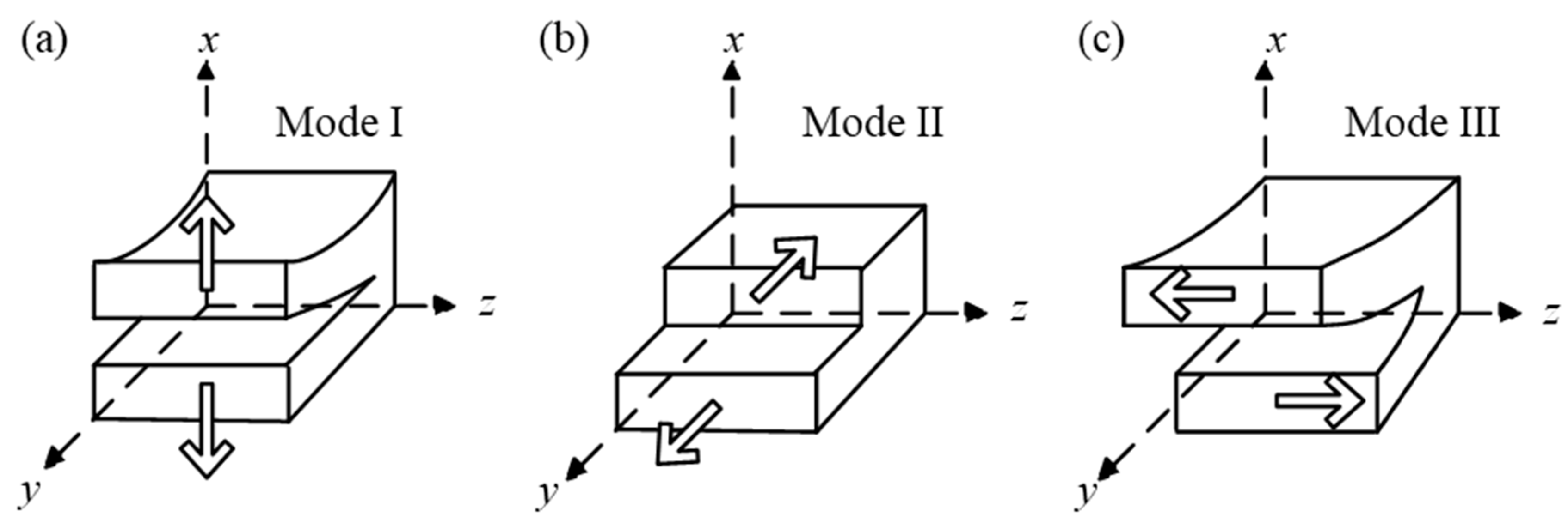
Figure 2.
DCB test (left) and 3ENF test (right).
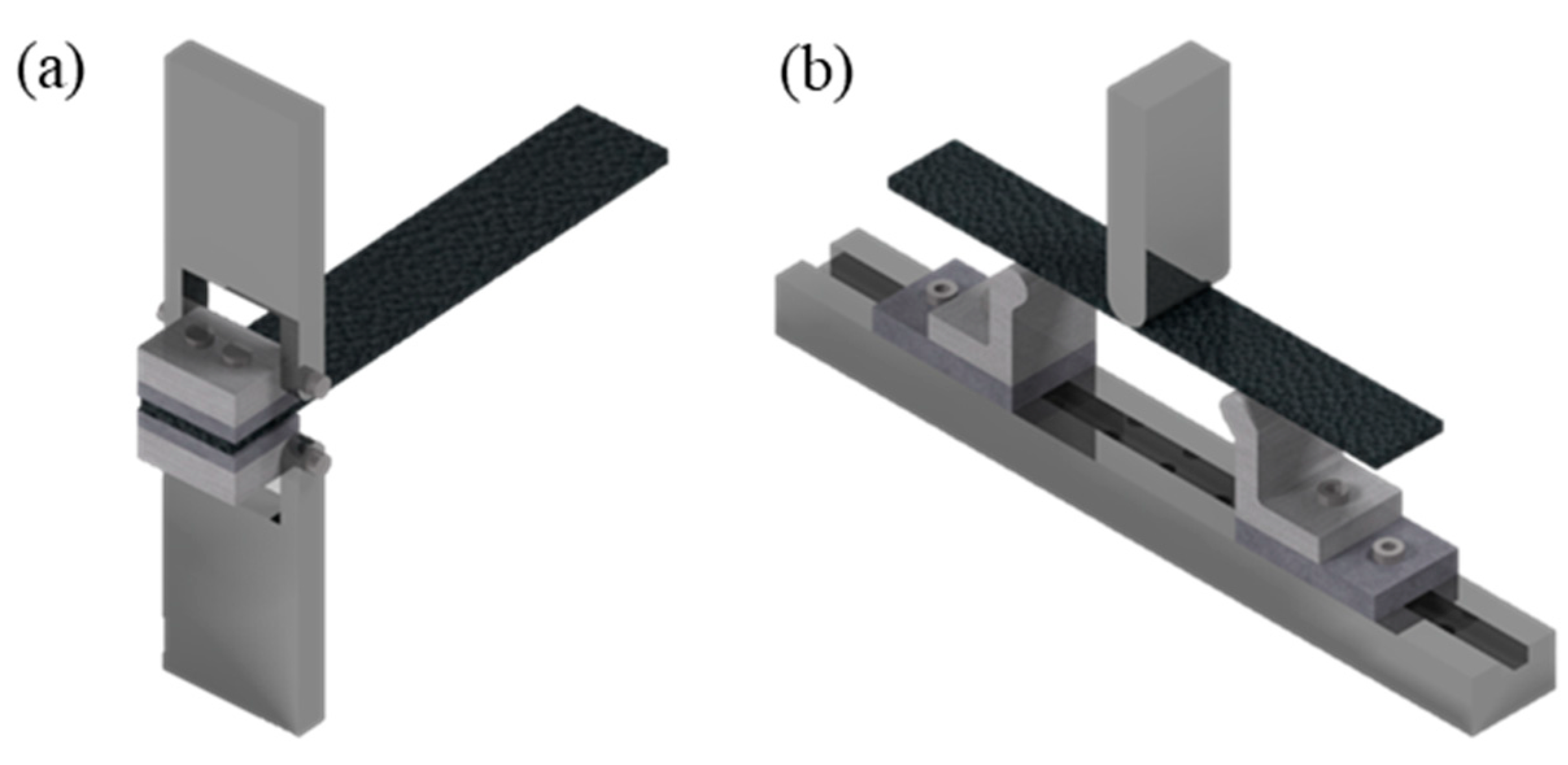
Figure 3.
MMB test.
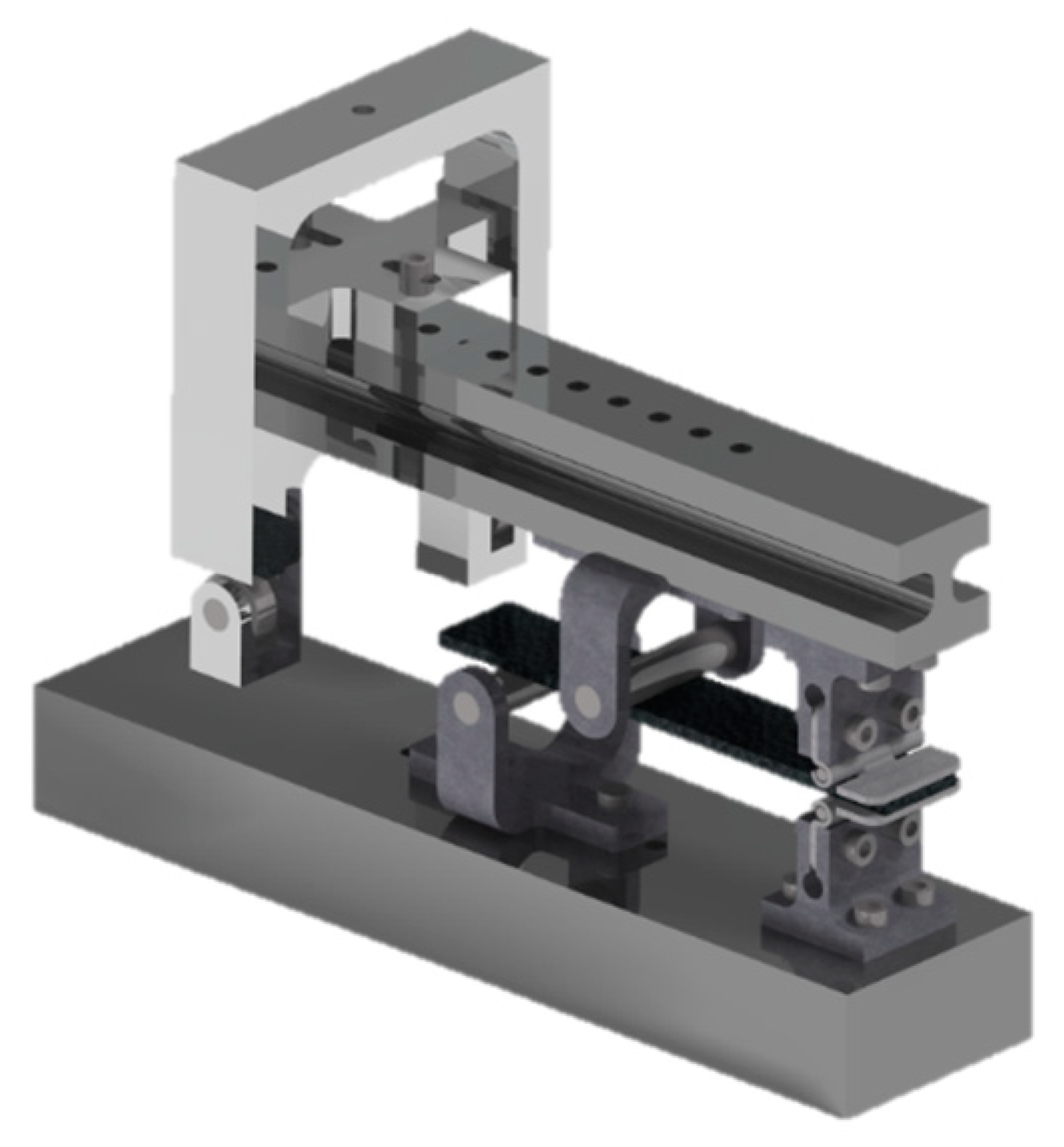
Figure 4.
Other Delamination Test. (a) Single-lap joints (SLJ) (b) Open-hole composite laminates (c) Angle-laid composite laminate.
Figure 4.
Other Delamination Test. (a) Single-lap joints (SLJ) (b) Open-hole composite laminates (c) Angle-laid composite laminate.
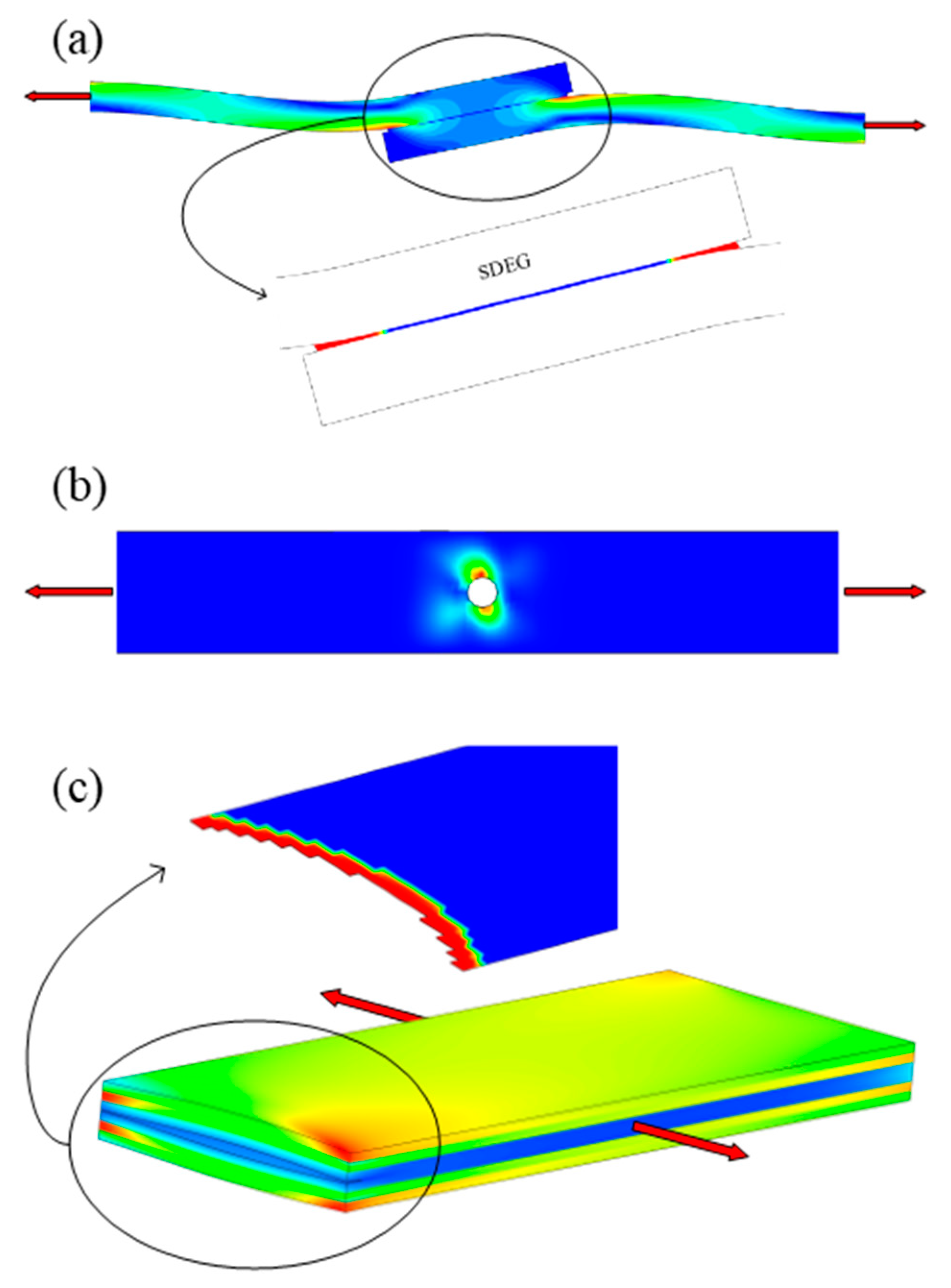
Figure 5.
Typical fatigue delamination growth onset curve.
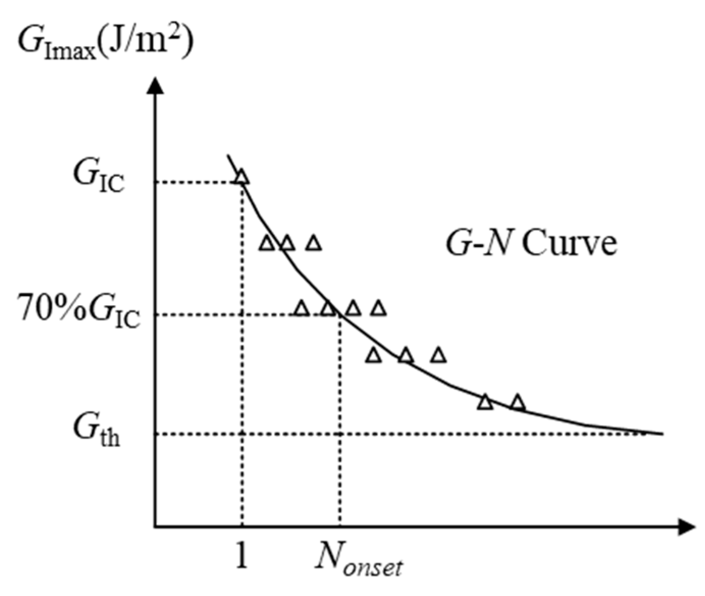
Figure 6.
Typical normalized fatigue delamination crack growth curve.
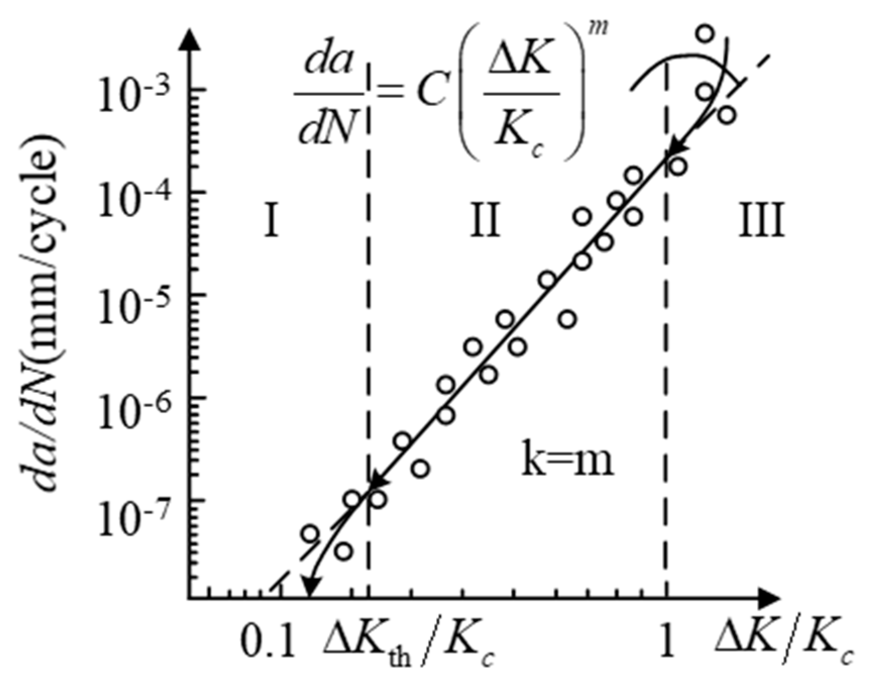
Figure 7.
Influence of on typical fatigue delamination onset/propagation curves. (a) The influence of on curve under monotone function. (b) The influence of on curve under monotone function. (c) The influence of on curve under non-monotonic function. (d) The influence of on curve under non-monotonic function.
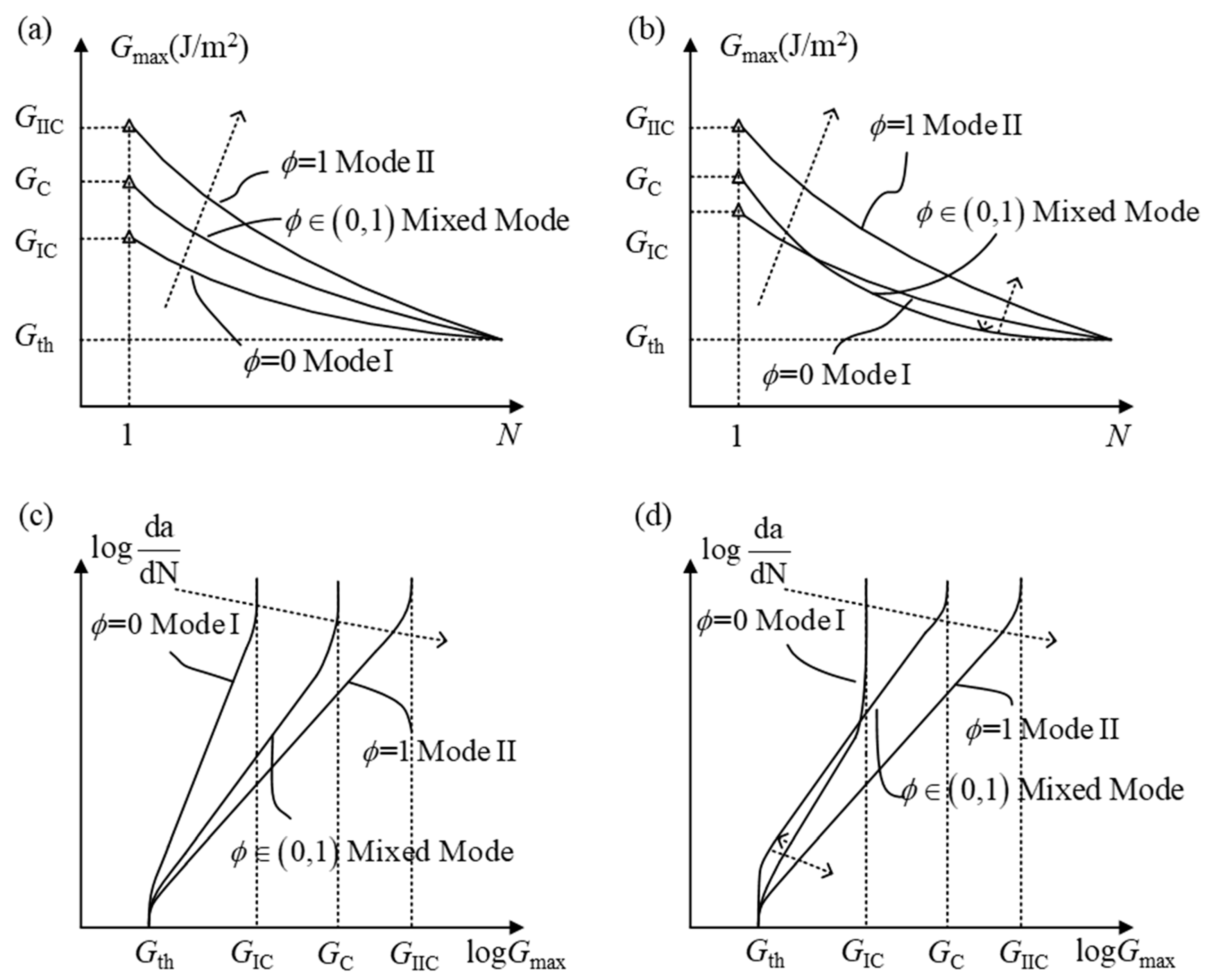
Figure 8.
Effect of fiber bridging on inter-laminar performance. (a) Influence of fiber bridging on. (b) Influence of fiber bridging on.
Figure 8.
Effect of fiber bridging on inter-laminar performance. (a) Influence of fiber bridging on. (b) Influence of fiber bridging on.
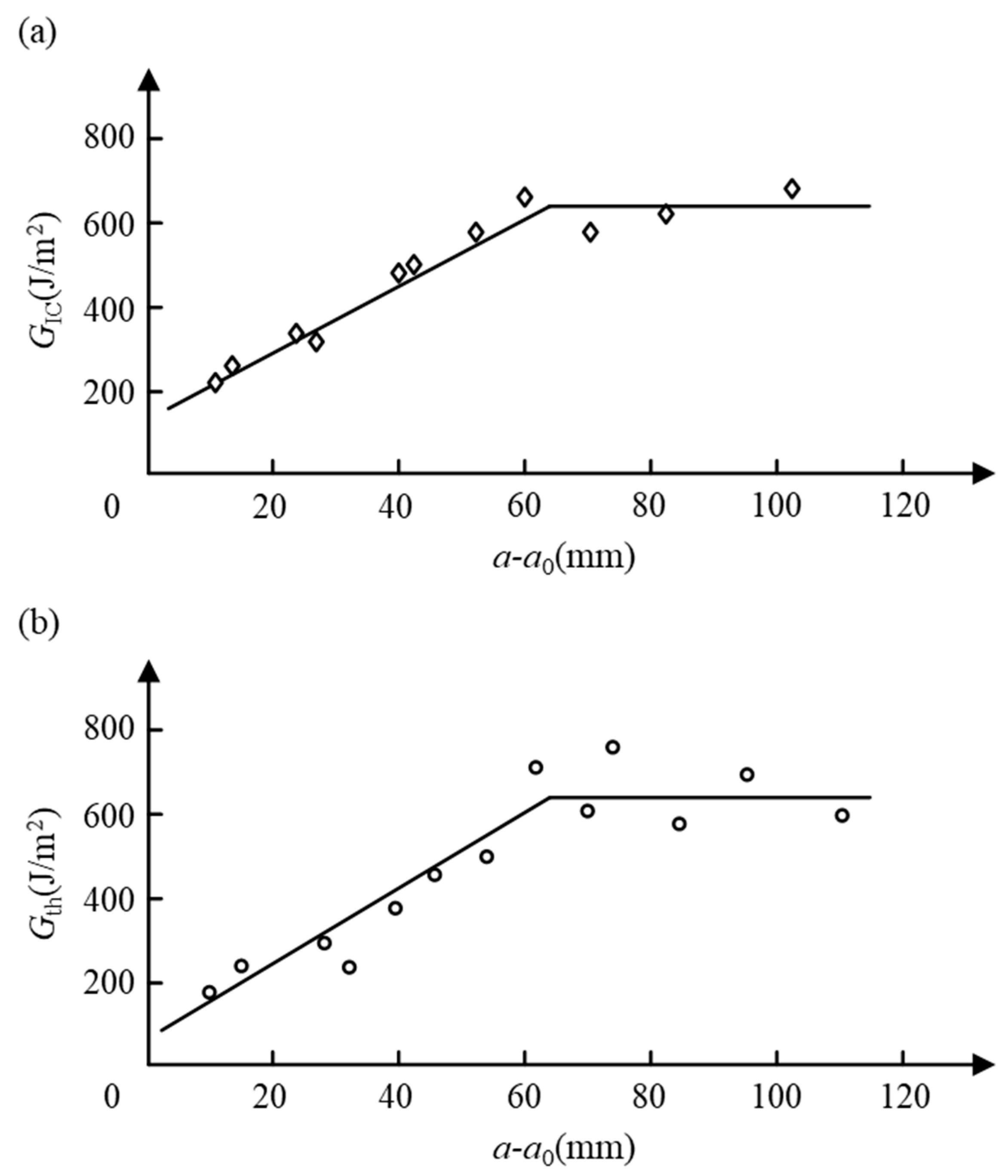
Figure 9.
Effects of on the delamination onset and propagation curves. (a) Influence of on the delamination onset curve. (b) Coupling influence of and on the delamination onset curve. (c) Influence of on the delamination propagation curve. (d) Coupling influence of and on the delamination propagation curve.
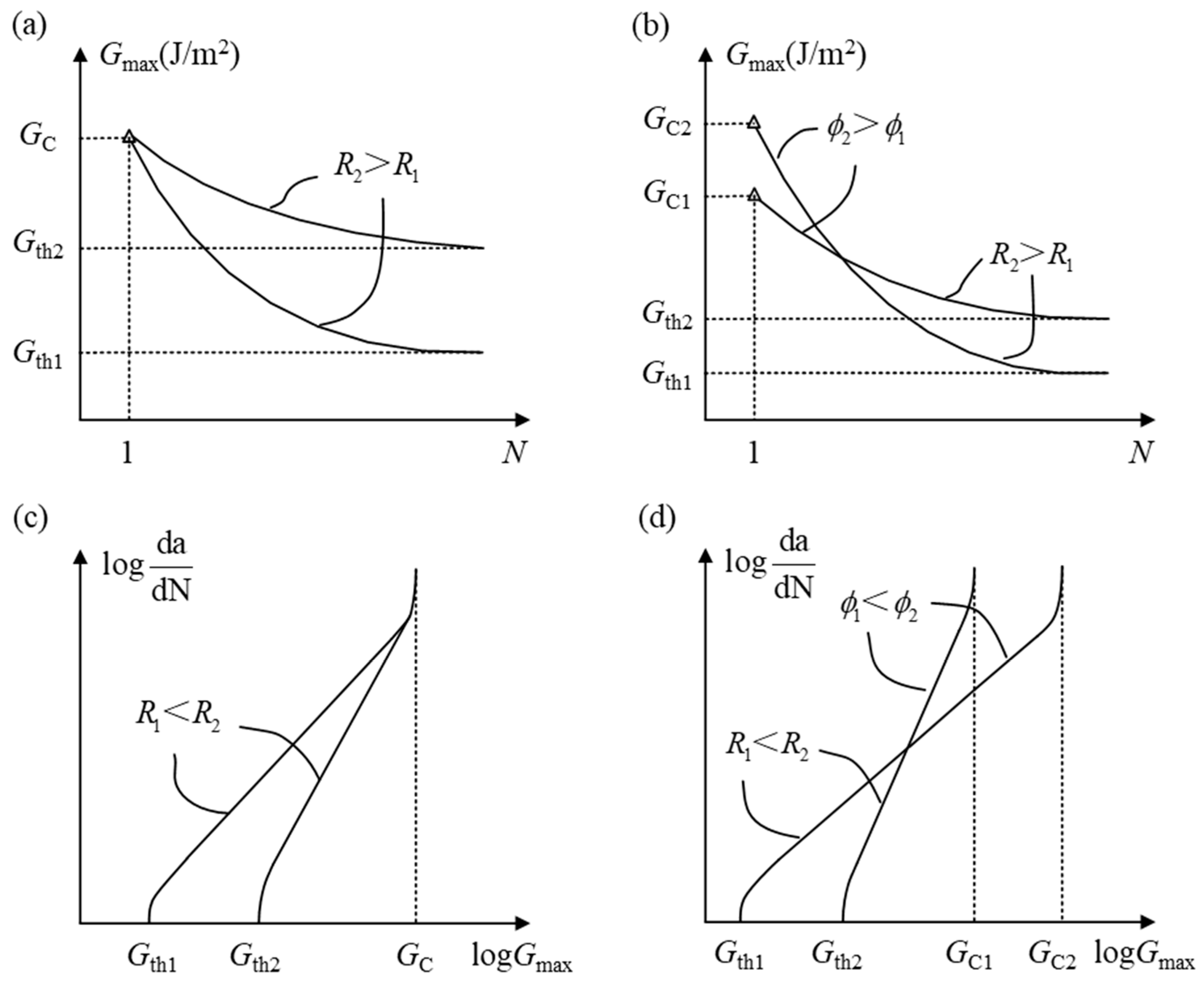
Figure 10.
The schematic diagram of calculating SEER by VCCT.
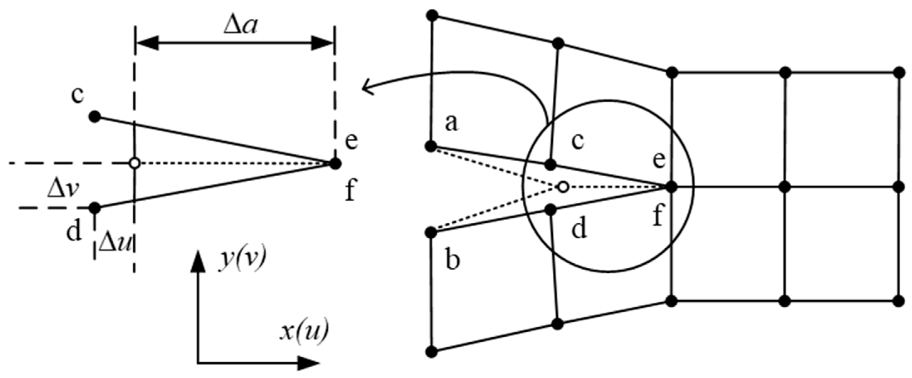
Figure 11.
Fatigue crack growth model based on Paris Law of fracture mechanics.
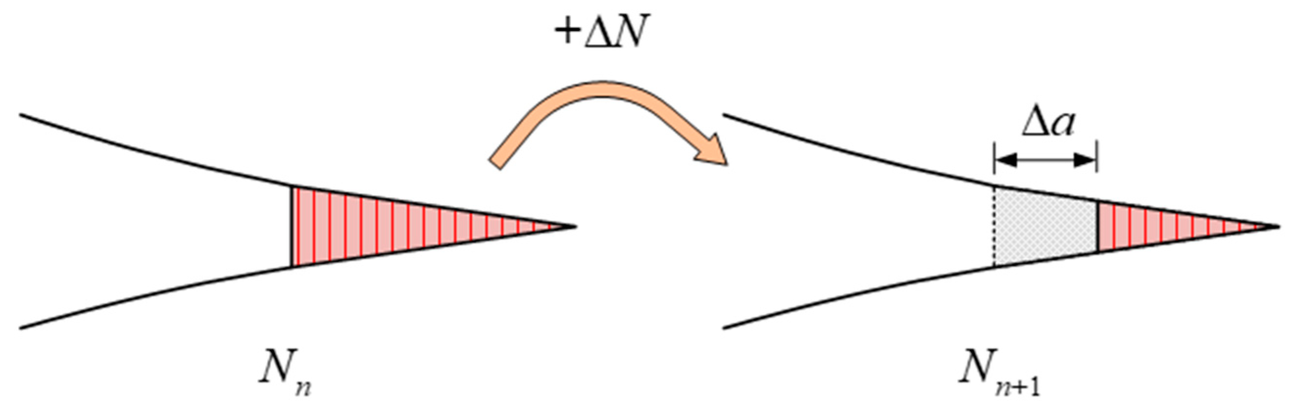
Figure 12.
Fatigue delamination model based on damage mechanics. (a) Fatigue delamination model based on the degradation of intra-laminar element (b) Fatigue delamination model based on the degradation of inter-laminar element (c) Fatigue delamination model based on the degradation of hybrid intra-laminar element and inter-laminar element.
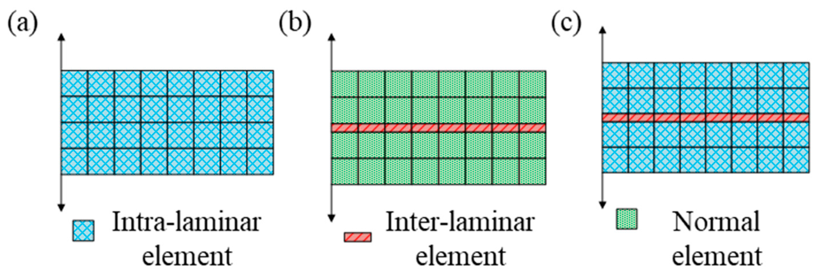
Figure 13.
Flow chart of fatigue delamination for the degradation of intra-laminar element.
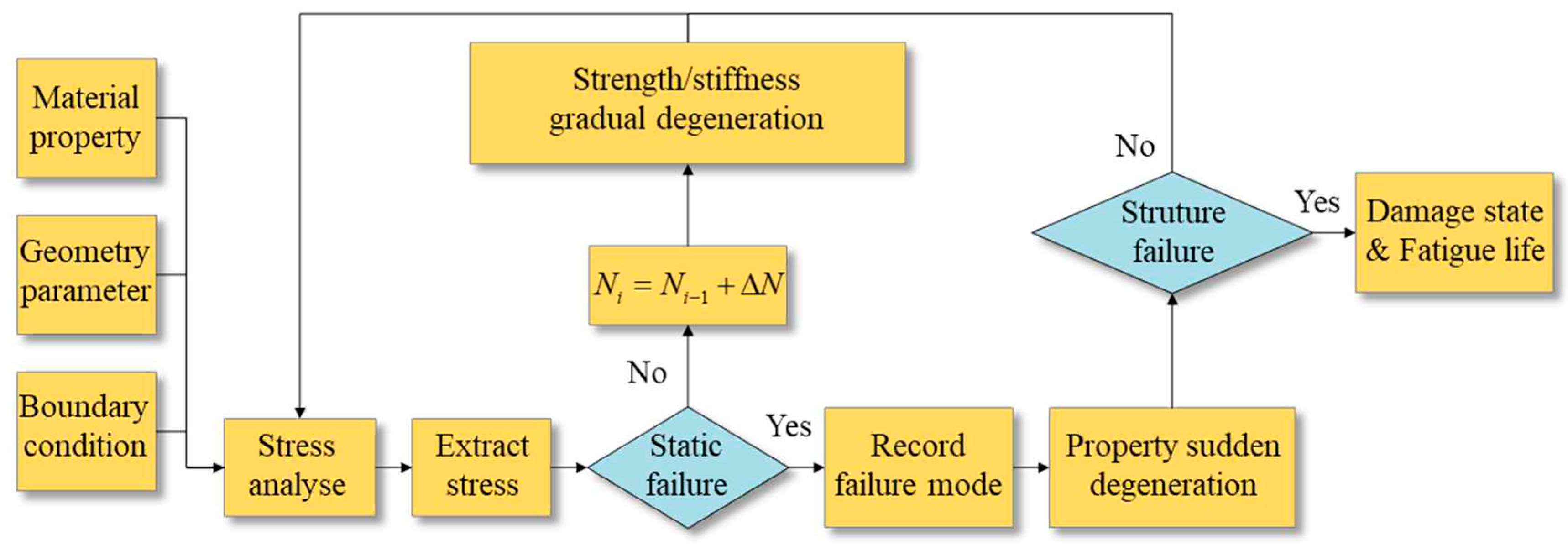
Figure 14.
Different constitutive relations. (a) Exponent law (b) Trapezoidal law (c) Bi-linear law (d) Tri-linear law.
Figure 14.
Different constitutive relations. (a) Exponent law (b) Trapezoidal law (c) Bi-linear law (d) Tri-linear law.
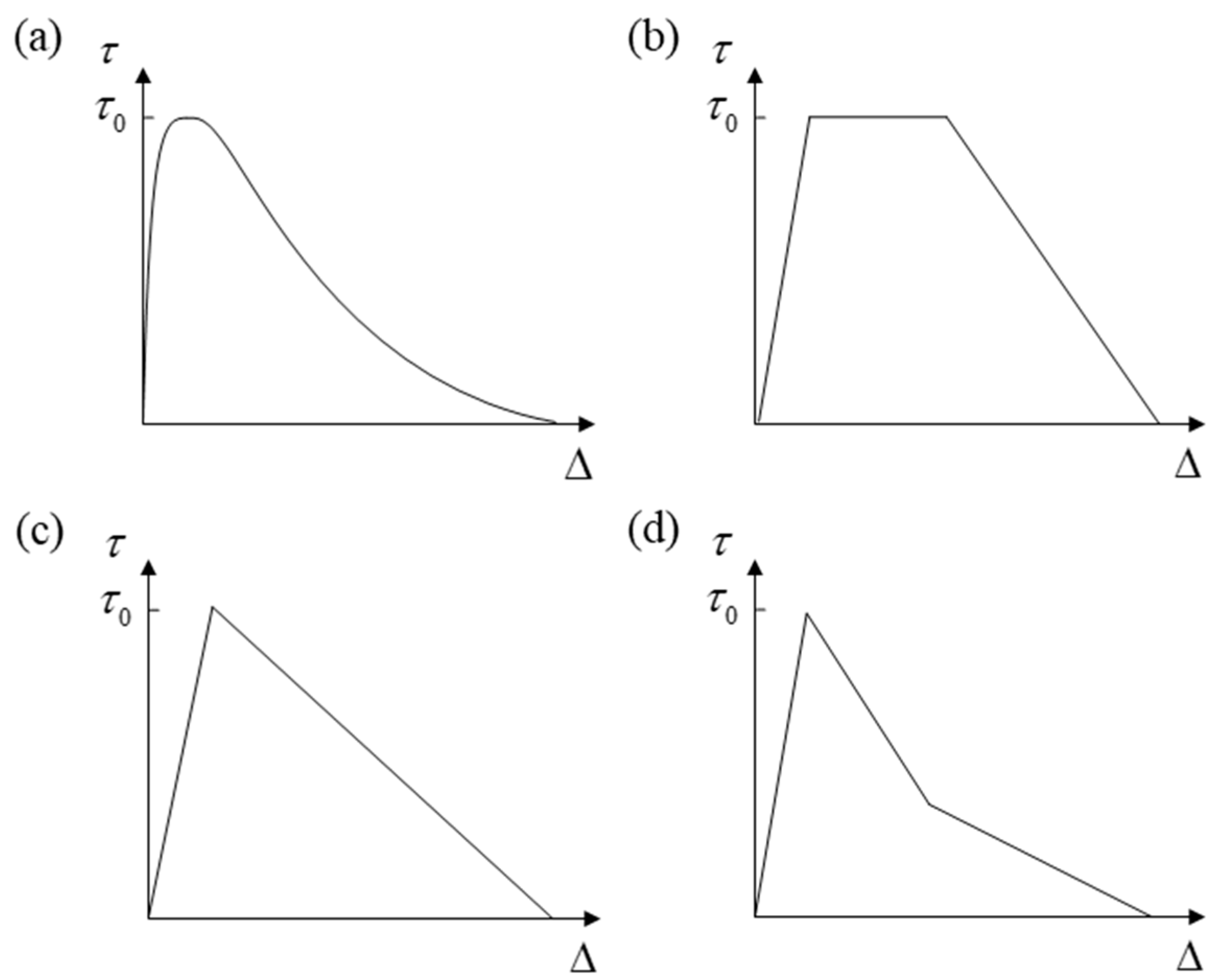
Figure 15.
The quadratic nominal stress criterion and B-K law.
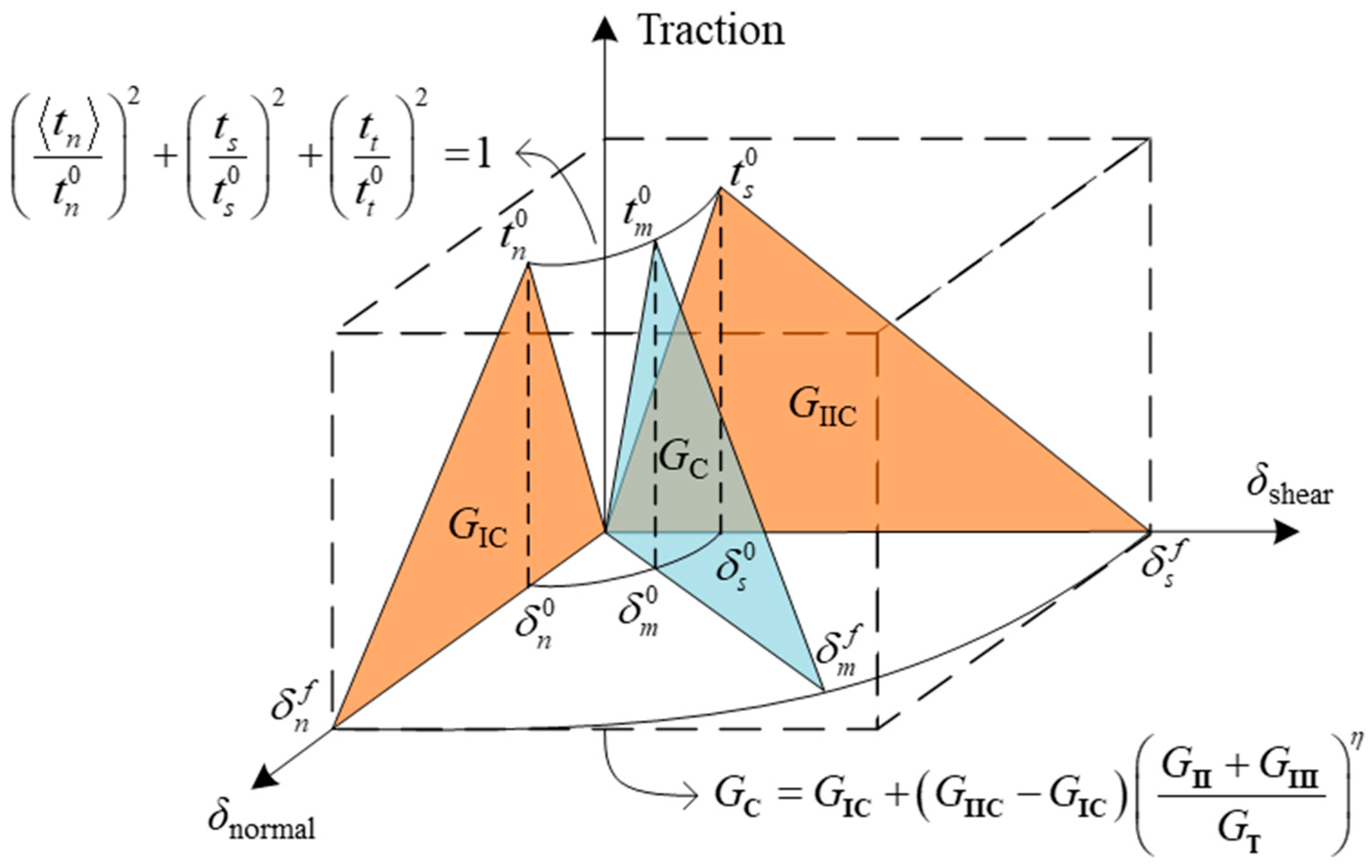
Figure 16.
Loading-unloading simulation model. (a) Loading-unloading hysteresis damage model. (b) Envelope load damage model.
Figure 16.
Loading-unloading simulation model. (a) Loading-unloading hysteresis damage model. (b) Envelope load damage model.
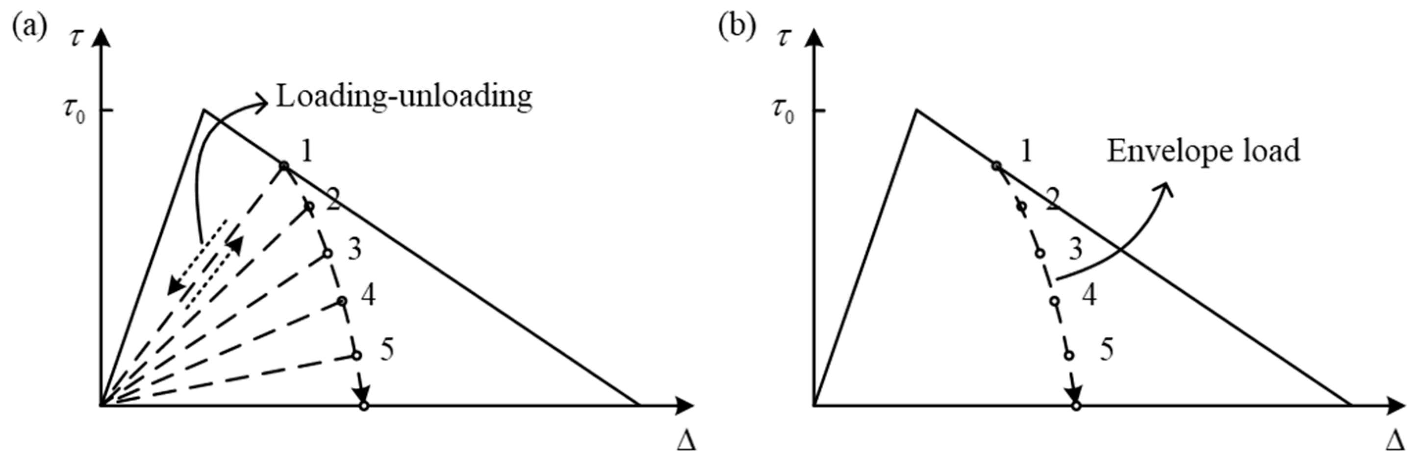
Figure 17.
Bilinear softening fatigue delamination model.
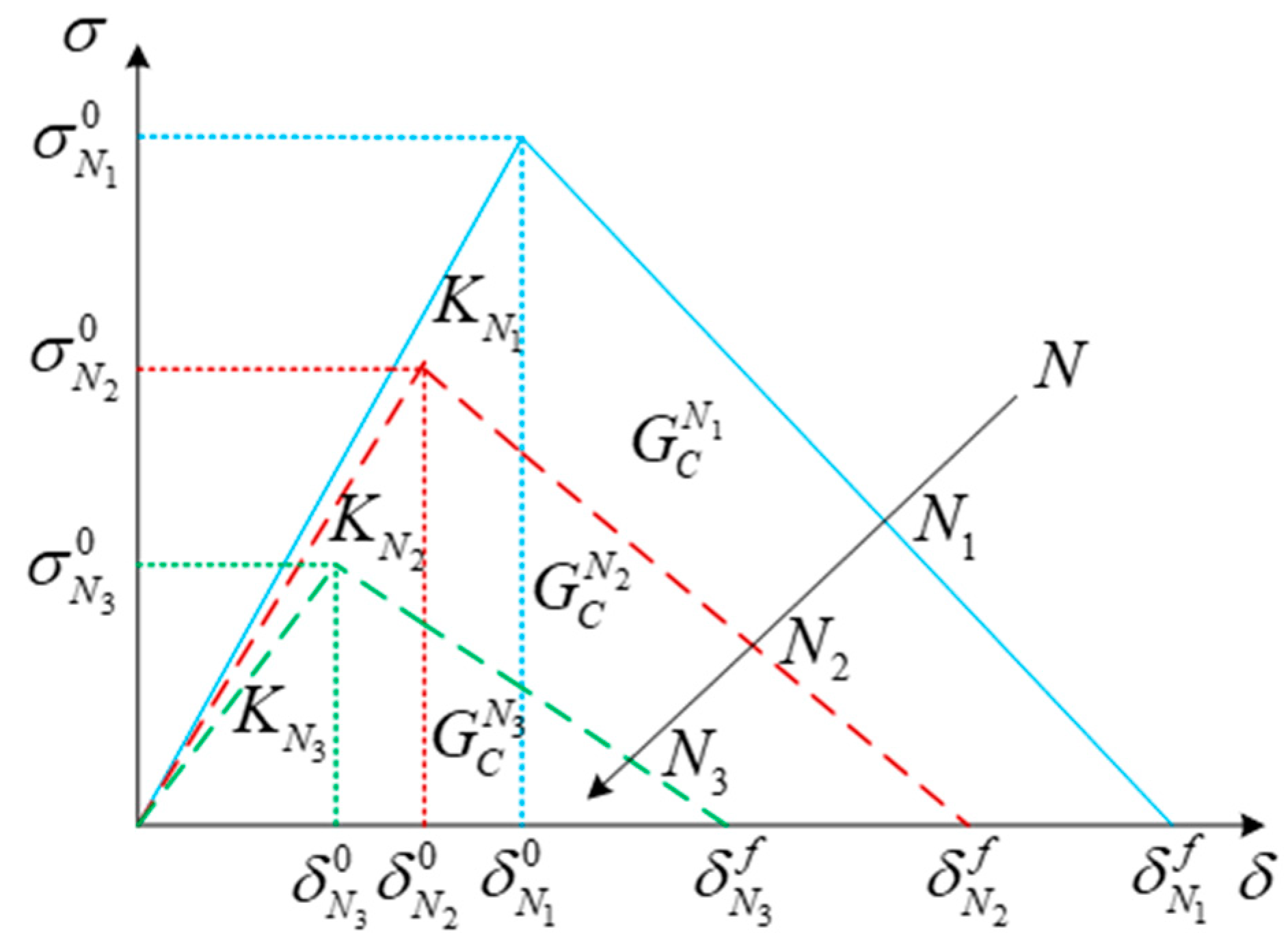
Figure 18.
FEM simulation results of DCB fatigue delamination damage. (a) DCB model. (b) Mises stress of element from crack front. (c) Damage variables of element from crack front. (d) Load-Displacement curve of DCB fatigue delamination. (e) Delaminated fatigue crack propagation and lifespan.
Figure 18.
FEM simulation results of DCB fatigue delamination damage. (a) DCB model. (b) Mises stress of element from crack front. (c) Damage variables of element from crack front. (d) Load-Displacement curve of DCB fatigue delamination. (e) Delaminated fatigue crack propagation and lifespan.

Figure 19.
Effect of mesh size on load-displacement curve of MMB test. (a) MMB model. (b) Comparison of results of L=0.5mm and L=2.0mm.
Figure 19.
Effect of mesh size on load-displacement curve of MMB test. (a) MMB model. (b) Comparison of results of L=0.5mm and L=2.0mm.
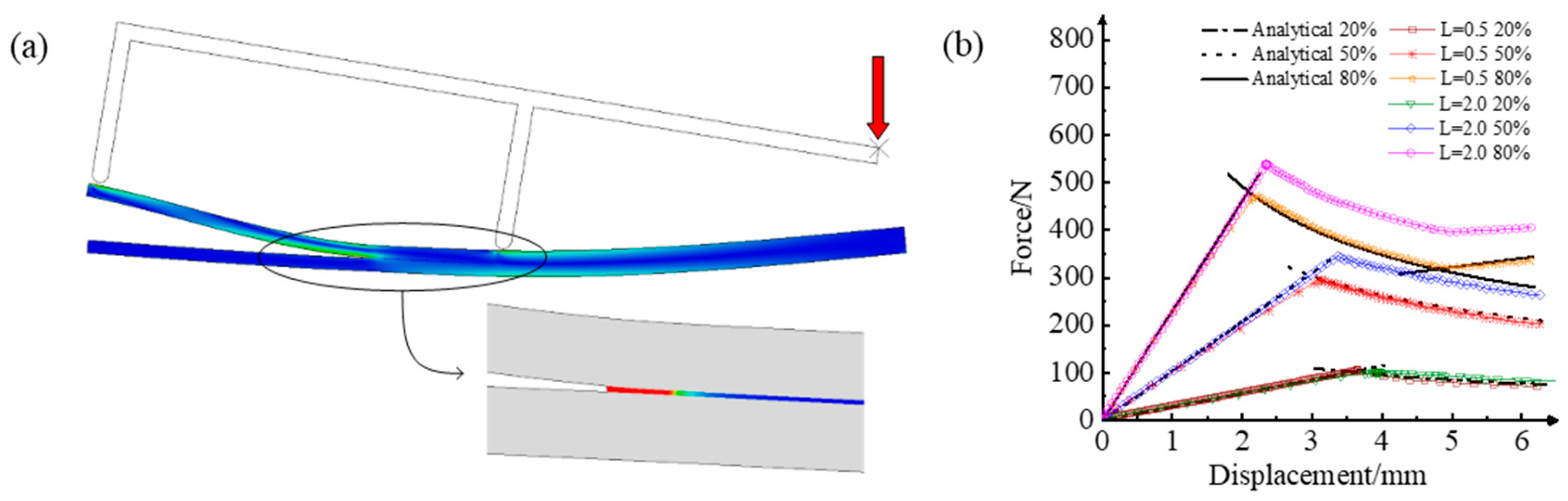
Figure 20.
Cohesive element test of high-cycle fatigue model by Turon. (a) Cohesive element model and Traction-log Cycles curve. (b) Traction-Displacement curve of element under fatigue load.
Figure 20.
Cohesive element test of high-cycle fatigue model by Turon. (a) Cohesive element model and Traction-log Cycles curve. (b) Traction-Displacement curve of element under fatigue load.
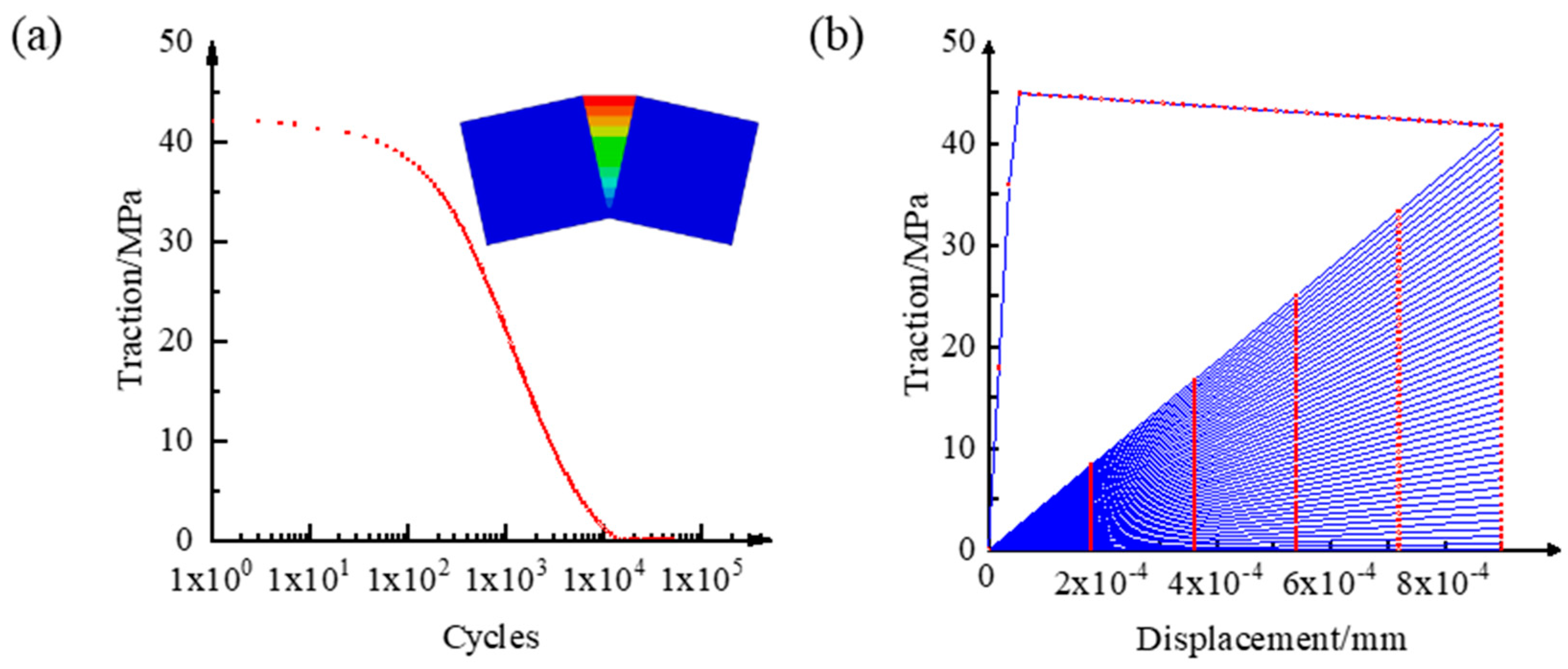

Table 1.
The commonly used microscopic strength failure criterion.
| Criterions | expression of |
|---|---|
| Hashin | |
| Chang-Change | |
| Hou | |
| Zou | |
| LaRC |
Table 2.
Common damage initiation/evolution criteria of delamination.
| Initiation criteria | expression | Evolution law | expression |
|---|---|---|---|
| Maximum principal stress/strain criterion | Power law | ||
| Maximum nominal stress/strain criterion |
B-K law | ||
| Quadratic nominal stress/strain criterion | Reeder law |
Disclaimer/Publisher’s Note: The statements, opinions and data contained in all publications are solely those of the individual author(s) and contributor(s) and not of MDPI and/or the editor(s). MDPI and/or the editor(s) disclaim responsibility for any injury to people or property resulting from any ideas, methods, instructions or products referred to in the content. |
© 2023 by the authors. Licensee MDPI, Basel, Switzerland. This article is an open access article distributed under the terms and conditions of the Creative Commons Attribution (CC BY) license (https://creativecommons.org/licenses/by/4.0/).
Copyright: This open access article is published under a Creative Commons CC BY 4.0 license, which permit the free download, distribution, and reuse, provided that the author and preprint are cited in any reuse.


