
Submitted:
06 October 2023
Posted:
09 October 2023
You are already at the latest version
Abstract
Current scientific knowledge and guidelines in bone and soft tissue augmentation, suggest the use of
staged surgical workflows as gold standards in regenerative procedures during implant therapy. In this
context, the process is always the same regardless of the techniques applied: an
alternate series of surgical acts is following one another after the completion of a specific period of
osseointegration or graft maturation. As a result, the overall surgical treatment is often long, invasive and
induce scar tissue formation.
This article proposes a novel, fast and less invasive biphasic protocol with the use of a well documented
cortical barrier mounted on stock healing abutments that are further replaced by customised abutments
on an early second stage. 2 cases are reported, one for an upper maxillary edentulous area and the other
for a mandibular, with a total of 4 implants placed.
Results at 4 months post op, showed an optimal soft tissue configuration for both cases with adequate
cervical profile generation and sufficient supracrestal complex height above the implant platforms.
Significant bone gains were also recorded through CBCT data collection either with alveolar width
measurements on axial slices, superposition of preop and postop datasets and 3D visualization after bone
volume segmentation.
Further studies will be needed in the future to evaluate the efficacy of this protocol in both hard and soft
tissue augmentation for edentulous sites in need of implant rehabilitation.
Keywords:
Cortical Lamina
; Customised Abutments
; Bone Augmentation
; Cervical Profile
; Dental Implants.
1. Introduction
Bone regeneration and augmentation in dental implantology, is a specific area of interest both for researchers and clinicians. The basic elements that consist of its foundations, have been well defined in the past and provide nowadays guidelines for success in the main clinical practice. However, only recently the importance of soft tissue augmentation and optimisation have been added in the process as a whole. Keratinised tissue preservation or promotion and cervical profile generation, are now accepted by the scientific community as key aspects of success in regenerative surgery. As a consequence, a novel “Hybrid" hard and soft tissue orientated surgical augmentation approach, is considered to be the best treatment strategy for stable results over the years. Nevertheless, current regenerative protocols support an analytical-staged workflow where each surgical act is followed by another one after a specific time period, which refers either to implant osseointegration or to hard/soft tissue grafting material maturation. Under such circumstances, patients have to undergo long treatments that in many occasions reach 6 to 9 months till the impression stage. Therefore, several dental implant and biomaterial companies have introduced novel non absorbable or resorbable products, that promise to reduce surgical treatment (Bone regeneration - Implant placement - Soft tissue augmentation) duration to new lower standards and below the 6 month threshold. Regardless of these efforts, such products seem to fail to diminish the number of surgical invasive interventions that often result in postoperative complications, pain and scar tissue formation.
This Case Report features a new accelerated protocol for both hard and soft tissue augmentation with simultaneous implant placement, by using a cortical barrier mounted on healing abutments, and proposes a faster, less invasive surgical workflow based on smart tissue manipulation.
2. Materials and Methods
The present Case Report includes 2 cases, one for the upper maxilla and one mandibular.
The inclusion criteria for the enrolment of the 2 patients were:
- A.
- Patients seeking implant treatment and above 18 years of age,
- B.
- Patients who signed an informed consent and accepted to comply with the postoperative instructions and the follow up planning,
- C.
- Patients with a good oral hygiene and having no periodontal disease (Plaque scores <25%, no pockets during probing, BoP levels <25%),
- D.
- Patients having keratinised mucosa with a minimum of 4mm width on the edentulous, to be treated, sites.
The exclusion criteria were:
- A.
- Patient having pathologies that affect bone metabolism and wound healing,
- B.
- Pregnancy and/or lactation during treatment and healing period,
- C.
- Smokers.
Case 1:
A 72 year old female patient attended our clinic seeking rehabilitation treatment on the upper edentulous 13-14 area. The patient was a healthy non smoker without periodontal disease. A pre-op Cone Beam Computed Tomography (CBCT) was performed on the upper second quadrant. The CBCT results revealed an important 3 dimensional defect on area 13-14 with horizontal and vertical bone loss. Bone density was qualified as type 4 and the distance from the most coronal edge of the ridge to the sinus floor was sufficient to place dental implants (13mm for site 13 and 7,3mm for site 14). Residual endodontic filling material adjacent to the bone structure were identified on both 13 and 14 sites (Figure 1). The clinical examination of the site didn’t reveal any periodontal pockets on neighboring teeth and both 12 and 16 tooth elements received an ultrasound scaling prior to the surgical treatment (Figure 2).
The patient was treated with the Poncho Lamina accelerated protocol for multiple adjacent implants on both sites 13 and 14. For the implant treatment itself, we selected and used Straumann SLA BLT Implants (Straumann Group, Basel, Switzerland). Bone regeneration was performed with Genos porcine particulated graft (Osteobiol by Tecnoss, Turin, Italy) and a Curved Lamina barrier 35x35 (Osteobiol by Tecnoss, Turin, Italy). Soft tissue optimisation was performed with the use of the VPI Cervico System (VP Innovato Holdings LTD, Cyprus) for anatomical abutment fabrication and Cervical Profile generation.
The surgical workflow consisted of a 2 stage process:
- An initial stage for bone augmentation with simultaneous implant placement and emergence profile generation with the use of stock abutments (Duration: From beginning of treatment till complete implant osseointegration)
- A second one for soft tissue management and Cervical profile generation with the use of anatomical abutments (Duration: From implant osseointegration till complete graft maturation).
Stage 1:
Following local anesthesia (Articaine Hydrochloride/ Adrenaline) access to the edentulous ridge was provided with a 15C blade using intrasulcular buccal and palatal incisions from the distal area of tooth 17 till the distal aspect of tooth 21 and a mid-crestal incision on edentulous site 13-14 (Figure 3). The interdental papilla areas were carefully dissected in split thickness and 2 flaps (buccal-palatal) were meticulously elevated (Figure 4). The buccal flap was further released with a periosteal incision using a 15 blade and a periosteal elevator.
An alveolar expansion protocol using Densah drills (Versah LLC, Michigan, USA) followed on site 13 and a crestal, Versah protocol 1, sinus lift was performed for site 14 (Figure 5). A collagen sponge was carefully pushed through the 14 site osteotomy and 2 Straumann SLA BLT implants were inserted (10mm length for site 13 and 8mm for site 14) subcrestaly with a final torque of 35N.cm (Figure 6).
After the site preparation and implant placement were completed, a curved cortical Lamina 35x35 mm (Osteobiol by Tecnoss, Turin, Italy) was hydrated in sterile saline water for 5 minutes. Following the hydration, 2 openings were trimmed out using a rubber dam punch instrument. The openings’ location referred to the exact implants’ location on the surgical site and they were further widened and refined with a micro-blade (SM67 Swann Morton). The Cortical Lamina was finally shaped with a 15 blade and scissors according to site topography and 2 Straumann healing cups of 5mm diameter and 4mm height were positioned and secured through its openings (Figure 7).
Prior to the barrier-abutment compound preparation the site was overgrafted with 2 grams of Genos 0.5 gram (Osteobiol by Tecnoss, Turin, Italy) previously hydrated with sterile saline (Figure 8).
After the bone graft was set on the buccal and palatal sides, care was provided to remove any granules remaining over the implant platforms. Then the 2 flaps were gently pulled apart to enable the stock abutments-cortical membrane compound placement and the abutments were secured in place with a torque of 20 N.cm (Figure 9).
Flap closure over the barrier and the abutments was performed with a palatal release incision and 2 layers of sutures as follows (Figure 10):
- A palatal incision parallel to the alveolar ridge and located apically nearly 15mm from the marginal palatal soft tissue, leaving the periosteum intact, was performed prior to the placement of sutures. Then a split thickness preparation below the palatal flap was performed till the dissected area reached the incision limits. After confirmation of the communication between both entries the palatal flap coronal advancement was possible ensuring a primary closure.
- An intermediate layer of horizontal mattress monofilament absorbable Glycolon 4.0 adaptation sutures (Resorba, Nuremberg, Germany) were placed below the muco-gingival line to secure an additional stabilization of the cortical barrier on both buccal and palatal sides and coronal advancement of both flaps.
- A superficial layer of Vertical mattress (placed at the papillary areas between the adjacent, to the augmentation site, teeth) along with simple interrupted Glycolon 5.0 (Resorba, Nuremberg, Germany) closure sutures (placed at the inter proximal abutment areas) provided primary flap closure and papilla stabilization on their initial preoperative position.
- A superficial incision performed with a 15 blade deep in the vestibule was finally used to reduce the muscle pull during the healing postoperative period.
Following a 2 to 3 minute gentle compression over the palatal incision with a sterile gauze to assure hemostasis, post surgical instructions were given to the patient. She was advised to rinse with a disinfectant solution (BlueM Mouthwash, BlueM Oral care) 24 hours after the surgery and twice a day for a period of 1 month. The patient was also told to avoid brushing at the surgical site during the same period until the sutures were completely resorbed. Finally antibiotics - Augmentin 875/125 mg (2 times a day for 1 week) and Ibuprofen 600 mg (2 times a day for 5 days) were also prescribed.
Recalls were scheduled at 2 weeks, 1, 2, 3 and 4 months post op.
Stage 2:
3 months after the first surgery and an uneventful healing, the alveolar ridge showed an evident increase in its dimensions compared to the preop clinical situation (Figure 11). It was considered safe to remove the healing abutments from the osseointegrated SLA Straumann implants and replace them by anatomical abutments for cervical profile generation. In order to optimize the soft tissue we used the VPI Cervico system for the chairside fabrication of the 2 anatomical profiles (AL profile for implant 13 and PM for implant 14) mounted on 2 engaged provisional cylinders for regular platform BLT implants (Straumann Group, Basel, Switzerland) and nanohybrid flow composite (Vertise Flow, Kerr - KaVo Kerr, California, USA) (Figure 12).
Following the customised abutment generation a split thickness preparation was initiated with the help of a 15 blade starting from a depth of 2 mm from the marginal soft tissue level to avoid any interference with the non yet maturated grafted material (Lamina and particulate graft) below (Figure 13). Further extension of the splitting process with the blade and the assistance of a periosteal elevator, reached a level just below the mucogingival line at the buccal side and 5mm apically of the soft tissue margin at the palatal side. Two split thickness flaps (Buccal and Palatal) were raised, the 2 healing abutments were removed and a 6mm supracrestal complex height from the implant platform till the marginal tissue edge was evaluated with a periodontal probe (PCPUNC156 Hu-Friedy, HuFriedyGroup, Chicago, USA) for both 13 and 14 sites (Figure 14).
The 2 anatomical VPI Cervico abutments were placed and secured over the implants after their surface was disinfected with alcohol and cleaned with a steamer. The 2 flaps were then secured around the abutments with 5.0 silk interrupted sutures and compressed trimmed pure collagen (Spongostan - Ethicon Inc, Somerville, USA) was used in the interproximal areas to fill the spaces between the flaps’ marginal edges (Figure 15). The same post surgical instructions, as in Stage 1 procedure, were given to the patient and Azithromycin 500 mgr was prescribed (1g single same day dose) to enhance the soft tissue healing.
Case 2:
A 68 year old female patient attended our clinic and requested a fixed solution for the posterior edentulous 35-36 area of quadrant 3. The patient was a healthy non-smoker without active periodontal disease (no attachment loss, pockets on probing and BoP). A pre-op Cone Beam Computed Tomography (CBCT) was performed on the lower third quadrant. The results revealed an important horizontal atrophy of the ridge at the area from the distal aspect of the 34 tooth element till the mesial aspect of 38 wisdom tooth. Bone density was defined as type 3 and the distance from the most coronal edge of the alveolar ridge to the inferior alveolar canal was enough to place dental implants (more than 10mm). Residual endodontic filling material within the bone structure was identified on area 36. A periapical lesion apically of 38 roots with underfilled root canal treatment and bone loss at the furcation area was also noted (Figure 16).
The clinical examination revealed a keratinised tissue width of 4mm upon a thin alveolar ridge, a mesioversion of the 38 element that additionally presented a type 2 mobility and a narrow class 3 furcation (Figure 17).
We decided that the short rooted element 34 should be extracted and replaced by a dental implant immediately after extraction along with a Poncho Lamina accelerated protocol for both 34 and 36 implant sites. As the 27 tooth was missing and the patient didn’t want to replace it, an implant rehabilitation for a future 3 unit bridge 34-36 was selected as the best treatment option. The Tooth 38 was left to be extracted at Stage 2 of the surgical procedure. In this particular case we used the same material as in case 1 but we added Everstick glass fibers to fabricate a provisional 3 unit fixture for cervical profile generation 34-36 during stage 2 procedure.
Stage 1:
Following local anesthesia (Articaine Hydrochloride / Adrenaline) the same surgical workflow was followed as in case 1: After flap elevation and release on both sides of the ridge, the tooth
element 34 was extracted and 2 Straumann SLA BLT 4.1 diameter implants (10mm length for the 34 implant and 8mm length for the 36) were placed subcrestaly with the Versah expansion protocol at a primary stability of 35N.cm. The site was overgrafted with 2 grams of Genos 0.5g and the trimmed Curved Cortical Lamina was secured above the implant platforms with healing abutments of 5mm diameter and 6mm height (StraumannGroup, Basel Switzerland) (Figure 17). Flap closure was achieved around the healing cups with the 2 suture layers and same suturing material described on Stage 1 and muscle pull reduction was achieved with a superficial incision on the depth of the vestibule as previously noted.
Post surgical instructions and medication were identical as in Case 1 and the patient was advised to avoid chewing hard consistency food at the left side of the mouth cavity.
Stage 2:
2 months after the first surgery, the Straumann healing abutments were removed from the SLA osseointegrated implants. The healing caps were replaced by VPI Crevico anatomical abutments using the corresponded surgical steps as in the same stage of case 1 (Figure 18). However, in this particular case a 3 unit fixture was generated to prepare the site for a future 34-36 bridge. Two anatomical abutments 34 and 36 were fabricated using non engaged Straumann provisional cylinders (Straumann Group, Basel, Switzerland) and nanohybrid flow composite (Vertise Flow, Kerr - KaVo Kerr, California, USA). The pontic element’s generation was based on the Cervical Socket Plug technique’s protocol (Figure 19). Using cylindrical diamond burs at high speed, 2 grooves (one buccal and one lingual) were made on all 3 units at their most coronal edge. After the 34, 36 abutments were secured over the implant platforms and the pontic profile unit was correctly positioned, nanohybrid composite flow filled the coronal area of the interproximal spaces in order to connect the 3 profiles. The connection was furthermore enhanced with the placement of everStickPERIO glass ionomer fibers (GC Europe N.V.) in the groove area of the 3 units, covered with flow composite. The fixture was then removed from the surgical site, polished and composite was carefully trimmed out from the apical areas of the interproximal spaces to assure interdental cleaning (Figure 19).
After the sutures were placed, we used a diode laser device (Smart M Pro, Lasotronix, Piaseczno, Poland) with a 980 nm optic fiber activated for photoablation at 2,5W for deepening the vestibule at the area buccally of the pontic and 36 sites (Figure 20) Finally, the occlusion was carefully corrected to avoid any contacts of the profiles with the antagonists, postoperative instructions and medication were prescribed as in case 1.
Data Collection
CBCT images were obtained using a CS8100 3D Carestream computed radiography system (Carestream Health, USA), at 0,150mm voxel size and field of view 8x9 cm prior (T1) and 16 weeks (T2) after implant placement. The original files in -DICOM format- were imported into the Romexis software (Planmeca Oy, Tuusula, Finland) for analysis. Both T1 and T2 datasets were superimposed in the software, using a point-based registration and if needed further manual alignment by an experienced oral imaging specialist. 2D measurements were acquired on both registered volumes where a slider tool could help hide and show the second superposed volume. First, measurements on T1 were done, after on T2. The cross-section in the middle of the site on the axial slice, and perpendicular to the alveolar crest was used to measure alveolar widths at 1mm, 3mm and 5mm heights (Figure 21, 22). An approximate Bone volume segmentation of the bone gain was performed on both volumes using a manual segmentation tool to visualize the gain in 3D (see Figure 23).
3. Results
Clinical evaluation for soft tissue and CBCT data analysis for hard tissue configuration were set for both cases at T1 - preop and T2 - 4 mo post op.
Soft tissue Configuration results:
Both cases revealed adequate soft tissue configuration with “mimicking the nature” cervical profiles after the removal of the VPI Cercico abutments at T2 (Figure 24 and Figure 25).
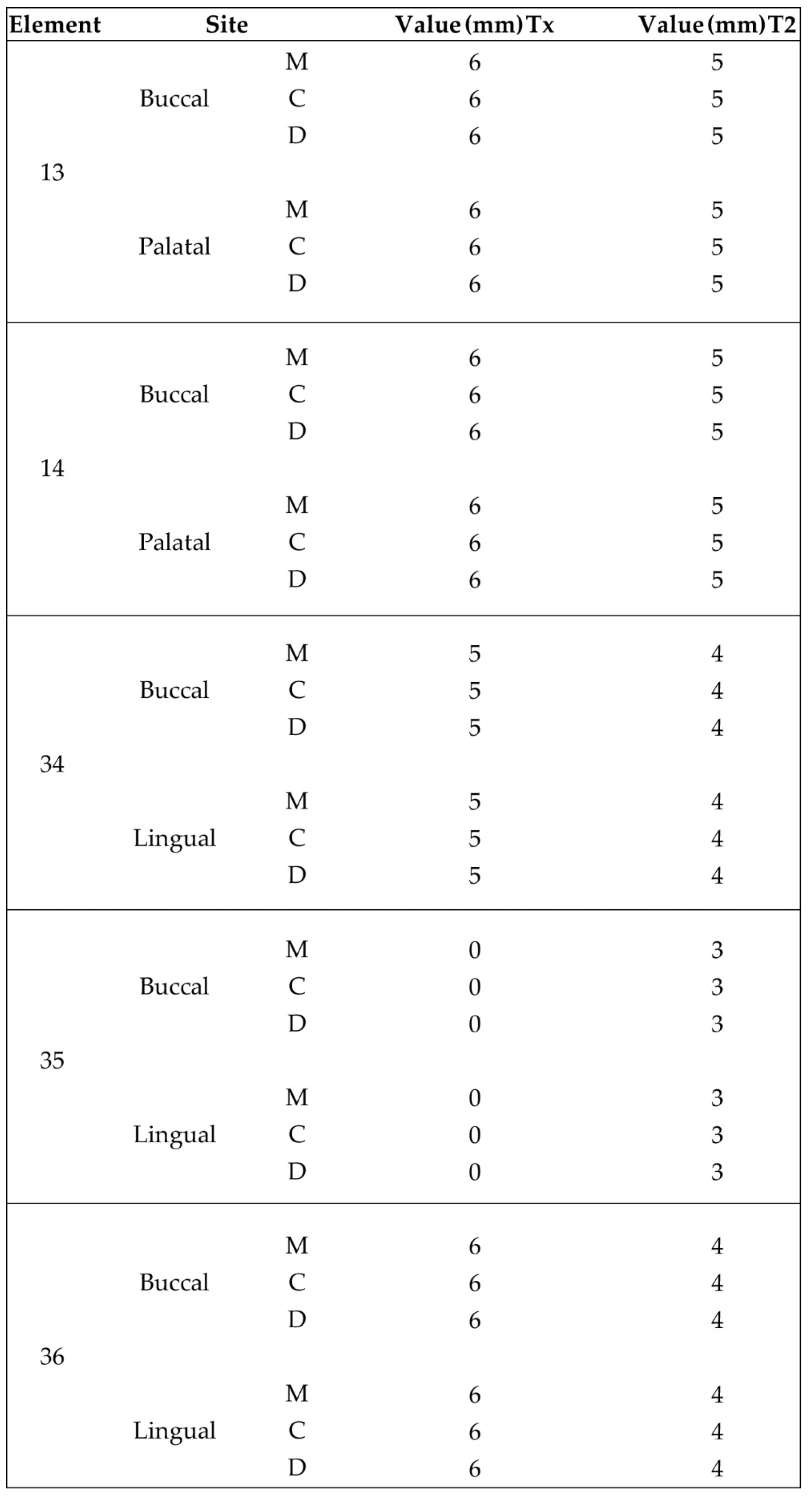
Implant supracrestal complex height was recorded with the help of a periodontal probe (PCPUNC156 Hu-Friedy, HuFriedyGroup, Chicago, USA) for all upper and lower sites at Tx (Stage 2) and T2 (Figure 26 and Figure 27).

Table 1.
shows results at a mm scale taken at 6 perimetric (Mesio-Central-Distal) points both on buccal and palatal/lingual sides. The height was evaluated from the implant platform till marginal soft tissue edge.
Table 1.
shows results at a mm scale taken at 6 perimetric (Mesio-Central-Distal) points both on buccal and palatal/lingual sides. The height was evaluated from the implant platform till marginal soft tissue edge.
Hard tissue Configuration results:
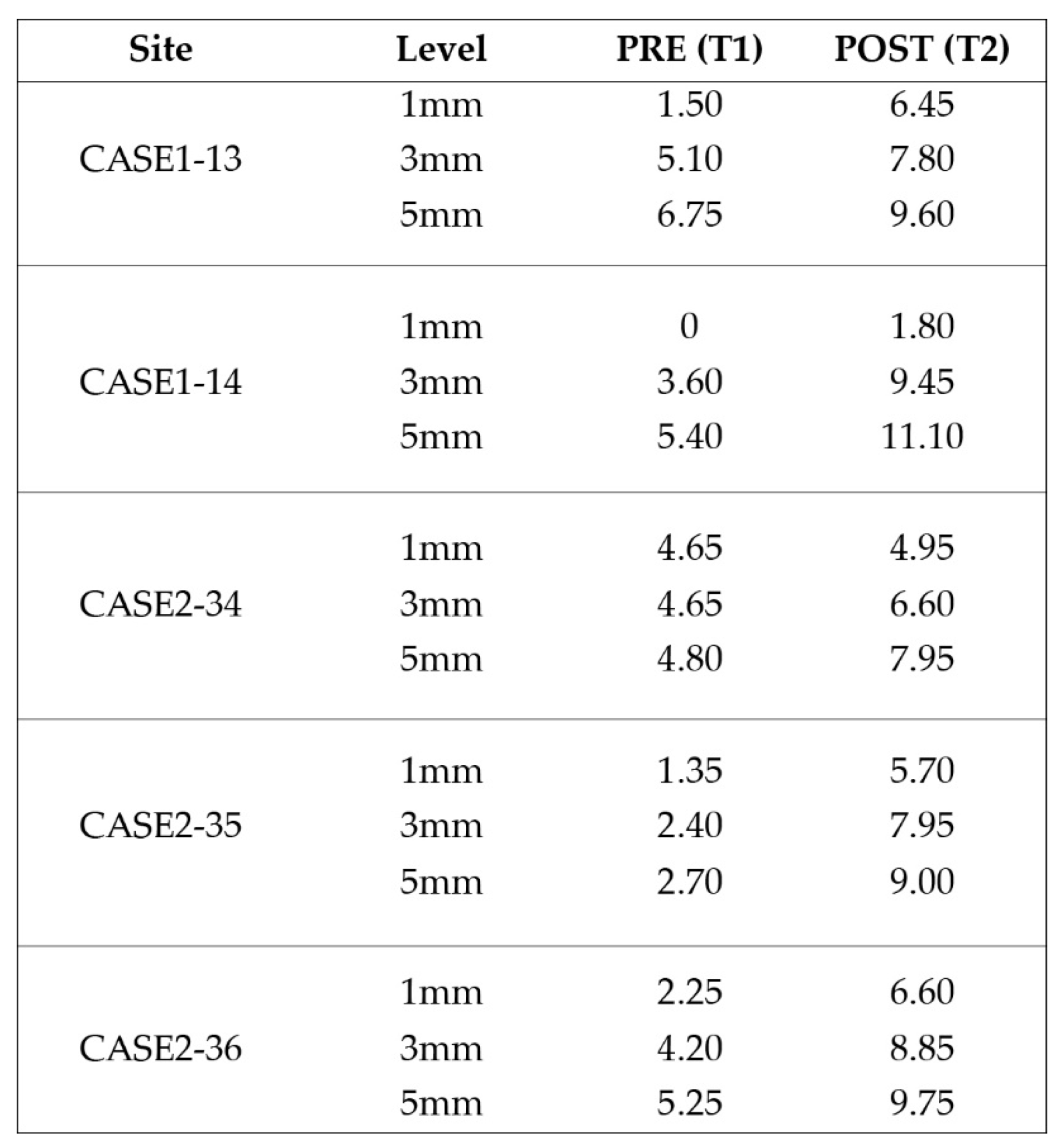
Table 2+ shows the alveolar width measurements at 1, 3 and 5mm heights in mm. The measurements were taken at T1 pre op and T2 post op. All T2 Values were increased compared to T1 at all 3 alveolar heights:
4. Discussion
The present article features a novel biphasic accelerated protocol which enables the surgeon to perform, in partial edentulous sites , implant treatment and both soft and hard tissue augmentation, in just 4 months.
In general, similar workflows especially in the case of 3d defects, require 3 surgical steps: During the first one, bone augmentation is performed with various techniques and only 4 to 6 months later the implants may be placed after bone graft maturation. Following implant osseointegration at stage 2, which normally takes 3 months in the mandible and 4 months in the upper maxilla, the final stage 3 for soft tissue management is initiated. In most cases, such management requires soft tissue grafting procedures (connective and free gingival grafts) from various donor sites (hard palate, tuberosity). Finally 1-2 months after soft tissue maturation, an optimized result with cervical profile generation is achieved by the means of provisional fixed prosthesis or customized abutments that are used during stage 3. Overall, we may conclude that during such processes, treatment duration takes at least 6 months. Even if the surgeon decides to combine the 2 first stages and place the implants simultaneously while augmenting the alveolar ridge, an optimal hard and soft tissue result will require 5 to 6 months (Figure 28). Taking in account the multiple interventions and the need of hard/soft tissue grafting with additional surgical acts on donor sites, the usual workflow may be both long, painful for the patient and include non negligible post operative risks such as postoperative bleeding (palatal donor sites), necrosis in intraoral hard tissue donor sites (eg chin and ramus areas), and site infection while using non resorbable materials (Titanium and PTFE meshes, tenting screws and pins) after exposure. In this context, every single intervention induces scar tissue formation that leads to a more difficult tissue manipulation on the following stage.
Compared to the above the poncho lamina accelerated protocol is based on a completely different strategy that features 2 main elements:
A combined implant placement and bone/soft tissue augmentation with the use of the Cortical lamina and the stock abutment compound during Stage 1. Besides the importance of the abutment-lamina compound some other features should be noted:
- -
- Good primary stability of the implants is primarily achieved with the implementation of osseodensification burs in bone density type 3 or 4. Versah drills also provide native bone preservation through ridge expansion, limit the risk of bone dehiscences during drilling, provide the possibility of adding a simultaneous crestal protocol 1 or 2 sinus lift and improve osseointegration by reducing direct contact of xenograft particles onto the implant surface whenever such grafting materials are used.
- -
- Overgrafting the site supplies the necessary volume for both hard and soft tissue augmentation. This prevents the need of soft tissue augmentation and additional interventions on donor sites at the following stage 2. The use of healing abutments over the implants add the foundations of an emergence profile generation very early in the treatment that will later be optimized at the following stage.
- -
- The occlusal connection of the lamina cortical barrier with the healing abutments provides a very precise and sufficient stabilization which prevents the use of additional fixation elements needed to be removed on a later stage (eg screws or pins). Horizontal mattress sutures further stabilize the barrier on a lower level over the grafting granulated material on both buccal and palatal/lingual sides of the site. The consistency and elasticity of the cortical lamina creates a firm structure that both protects the overgrafted material and ensures tenting support for the soft tissues.
- -
- The use of a specific incision design without vertical releases for further envelope flap elevation, preserves vascular integrity within the surgical site and tissue in the interproximal areas of neighboring tooth elements through partial thickness preparation. This meticulous, invasive site preparation is mandatory for bone graft integration and less soft tissue retraction during the healing period.
- -
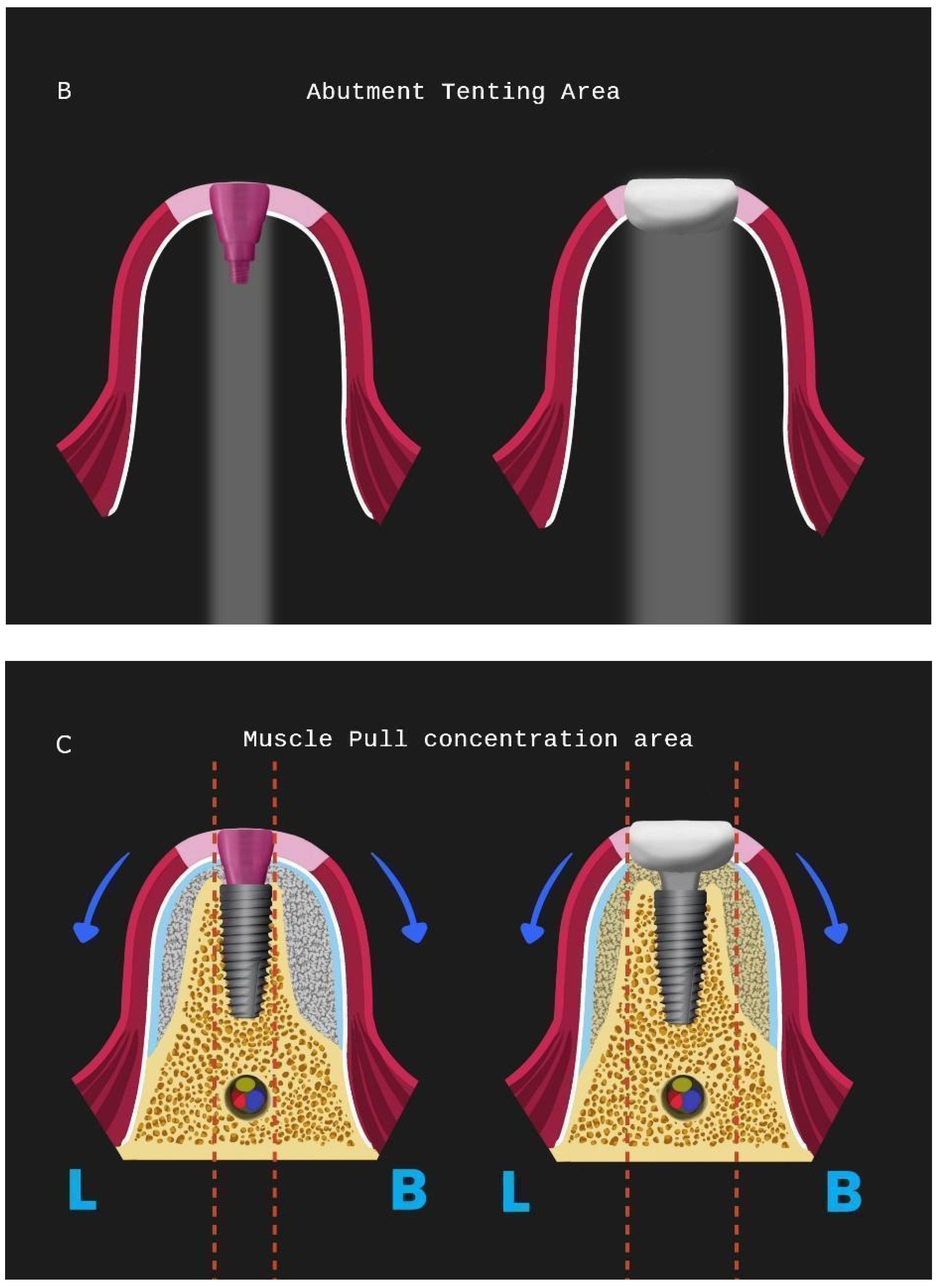
- A correct adaptation of the soft tissue around (case 2) or over the abutments (case 1 with primary closure) during flap closure is achieved with sutures placed at different layers. This enables a better distribution and absorption of the muscle pull force on the soft tissues that cover the barrier and reduce the risk of lamina exposure. Uncovered areas over the cortical sheet would lead to resorption and soft tissue apical migration. Further use of a superficial incision deep in the vestibule concentrates the muscle pull force in an area away from the flap marginal edges while palatal incisions parallel to the alveolar ridge in upper maxilla cases provide elasticity of the tissue for hermetic closure over the barrier (Figure 28).
The setting and initiation of the second stage earlier on the time frame through “a window of opportunity” created by the osseointegration rate (Tx, see Figure 28). When implant secondary stability is adequate to remove the healing abutments a layering - partial thickness preparation takes place and the anatomical abutments are used for cervical profile generation. However it is important to highlight some details concerning this soft tissue management stage:
- -
- The layering preparation is performed with partial thickness flaps to avoid any interference and trauma to any barrier remnants and granulated material below. The incision is located within the transitional zone and above the deep zone of the supracrestal complex (Figure 29). Any incision below that level may induce trauma to the vascular complex and rigid collagen type 1 fibers that provide tissue stability over the implant platform. This stability offers protects and preserves the integrity of the coronal part grafting material during its maturation and prevents further resorption. Although there are articles showing that partial thickness flaps also lead to bone loss, in general it is widely accepted that such surgical acts result in faster healing, less postoperative pain and protection of fragile structures in deeper layers of the site.
- -
- After the removal and replacement of the stock healing abutments, adaptation and marginal soft tissue flap edge closure could be better achieved with an apical reposition flap procedure rather than an hermetic closure around the customised abutments for cervical profile generation. This ensures keratinised tissue preservation and reduces the need for free gingival grafts which still may be used during this stage but are more invasive. Interproximal areas may remain often uncovered after flap closure, especially on upper maxilla cases, but the use of compressed collagen trimmed sponges provide the support for epithelial migration over their surface to promote papilla formation. This happens often in upper maxilla cases like the one demonstrated in this case report.
- -
- The precise moment of stage 2 initiation may vary and is dependent on the implant osseointegration rate. In reality, the use of implants with novel and more hydrophilic surface coating may trigger the layering process and abutment replacement earlier in the treatment (Figure 30).
In his case report we decided, along with the full protocol description, to present 2 cases which have a particular interest.
Case 1 features a 2 adjacent implant placement in the upper maxilla where a 3D defect is present. Along with the horizontal and vertical hard and soft tissue augmentation, a Versah protocol 1 crestal sinus lift was also added to the whole treatment. Attention was provided for the augmentation itself and the protection of the implants during the osseointegration period, in a region where keratinised tissue was sufficient. This is the main reason why primary closure over the healing abutments was selected at the end of stage 1.
Case 2 demonstrates a more demanding situation regarding soft tissue management as it required cervical profile generation for a future 3 unit bridge with pontic site development in an area where keratinised tissue is often scarce. Here instead of suturing the soft tissue above the abutments, the latter remained partially uncovered with the limited keratinised tissue secured around them. A full coverage of the abutment platforms would raise the risk of their early exposure through thin soft tissue and keratinised tissue loss.
In both cases attached tissue was still present at the end of soft tissue maturation around the implant sites, but we strongly advise to perform an apical repositioning of buccal flaps for upper maxilla cases rather than proceed to a simple tissue adaptation around the customised abutments and free gingival grafts, if needed, at stage 2 procedure for mandibular cases.
Supracrestal heights were recorded at Tx and T2 for both cases. The results were at least 4mm for mandibular sites and reached bigger values at the maxillary one, due to higher initial soft tissue thickness and primary closure over the abutment platforms at the end of stage 1. A 1mm loss was recorded when measurements were compared between Tx and T2. This height reduction conforms to other findings in the bibliography, especially concerning anterior sites when stock abutments are to be replaced with anatomical or provisional crowns. This is to take into consideration while positioning the implants at a subcrestal level during stage 1 procedure.
Despite the fact that the soft tissue data measurements report values above the necessary 4mm limit for an adequate and sufficient supracrestal implant complex height and cervical profile generation was achieved in all 5 upper and lower sites, STL files with superposition and volumetric analysis will be needed in future studies to evaluate the soft tissue gains at T2.
Significant gains in bone configuration were recorded via CBCT data collection and alveolar width measurements at 3 different levels of the ridge for both T1 and T2 datasets. Values at T2 for the 2 upper maxilla sites ranged from a minimum of 6.45mm to a maximum of 11.10mm with the highest difference T2-T1 recorded at the distal 14 site. Lower site values ranged from a minimum of 4.95 mm to a maximum of 9,75mm with the highest difference T2-T1 at the pontic site 35. Although these values were taken at different levels, if we consider that at least 1 to 2 mm of surrounding hard tissue are necessary for long term stability around dental implants, the current findings show exceptional hard tissue volume around all 4 implant sites. In particular, the value and importance of having a firm attachment and stabilization of the cortical barrier within the healing abutments platforms and over the overgrafted granulated material at a higher level that the one defined from the residual bony ridge at T1, is clearly demonstrated at the cross sectional CBCT images of the pontic site 35. Finally we may appreciate an overall 3D bone volume gain visualization at T2 after bone segmentation volume gains which confirm the results on the cross sectional images. Future studies could also include volumetric analysis on bone gains through STL files.
Following the above mentioned, the accelerated protocol with the poncho lamina technique presents advantages over the usual longer protocols already established in the bibliography and the clinical practice. It is clear that in this particular workflow the overall treatment duration is reduced through the correct use of its 2 basic elements, already described in this section. Nevertheless, the T1-T2 time length is dependent on the bone grafting material integration alone (Figure 28). This clearly suggests that in the future, novel bone regeneration grafting materials could further reduce the overall treatment duration below the 4 months limit. In our opinion, in this particular process the importance of reducing treatment time lies not only in providing a faster treatment for the patient. It is rather essential for the oxidative stress management during the healing period: As the window of opportunity at Tx with initiation of the layering process gets closer to the T1 timeframe, the use of anatomical abutments generated with the VPI Cervico system for a longer period till T2, shifts the muscle pull concentration area and provides a larger tenting area for the non maturated grafting material below. This might finally be of a greater importance than the treatment duration itself as it may have a great impact on the soft and hard tissue augmentation result at T2. In this context, an early soft tissue optimization management would set the ideal conditions for the overall hard tissue integration and configuration (Figure 31).
5. Conclusions
This article introduces a modern approach for simultaneous implant placement and bone/soft tissue optimisation with a reduced treatment duration that offers a faster, less invasive alternative for the patient in need of rehabilitation in partial edentulous sites.. 2 cases are presented showing significant gains on both hard and soft tissue volume and configuration. Further prospective case series studies are needed in the future to evaluate the efficiency and validity of the presented protocol.
Disclosure
The authors report no conflict of interest with anything in this article. No financial support was provided for this investigation.
References
- Serino G, Strom C. Peri-implantitis in partially edentulous patients: association with inadequate plaque control. Coin Oral Impl Res, 2009, 20, 169–174. [CrossRef]
- Wenstromm JL, Bengazi F, Lekholm U. The influence of masticatory mucosa on the peri-implant soft tissue condition. Clin Oral Impl Res 1994, 5, 1–8. [CrossRef]
- Souza AB, Tormena M, Matarazzo F, Araujo MG. The influence of the peri-implant Keratinised mucosa on brushing discomfort and peri-implant patient tissue health. Clin Oral Impl Res 2016, 27, 650–655. [CrossRef] [PubMed]
- Glauser R, Schupbach P, Gottlow J, Hammerle CHF. Peri implant soft tissue barrier at experimental one-piece mini-implants with different surface topography in humans: A light-microscopic overview and histometric analysis. Clin Impl Dent Relay Res 2005, 7 (Suppl 1), S44–S51.
- Giannobile WV, Jung RE, Schwarz F. Evidence-based Knowledge on the aesthetics and Maintenance of peri-implant soft tissues: Osteology Foundation Concencus Report Part 1-Effects of soft tissue augmentation procedures on the maintenance of peri-implant soft tissue health. Clin Oral Impl Res 2018, 29 (Suppl 15), 7–10.
- Grunder U, Gratis S, Capelli M. Influence of the 3-D bone-to-implant relationship on Esthetics. Int J Periodontics Restorative Dent 2005, 25, 113–119.
- Monje A, Chappuis V, Monje F, Munoz F, Wang HL, et al. The critical peri-implant buccal bone wall thickness revisited: An experimental study in the beagle dog. Int J Oral Max Impl 2019, 34, 1328–1336.
- Beretta M, Poli PP, Pieriboni S, Tansella S, Mandfredini M, et al. Peri-implant soft tissue conditioning by means of customised healing abutment: A randomised controlled clinical trial. Materials (Basel) 2019, 12, 3041. [CrossRef]
- Sanchez IS, Ortiz Vigon A, Sanz Martin I, Figuero E, Sanz M. Effectiveness of lateral bone augmentation on the alveolar crest dimension: A systematic review and meta-analysis. J of Dent Res 2015, 94 (9 Suppl), 128S–142S. [CrossRef]
- Oh SL, Masri RM, Williams DA, Ji C, Romberg E. Free gingival grafts for implants exhibiting lack of keratinised mucosa: A prospective controlled randomised clinical study. J Clin Periodontol 2017, 44, 195–203. [CrossRef]
- Esposito M, Grusovin MG, Felice P, Karatzopoulos G, Worthingtonet HV, et al. The efficacy of horizontal and vertical bone augmentation procedures for dental implants-Cochrane systematic review. Our J Oral Implant 2009, 2, 167–184.
- Mittal Y, Jindal G, Gary S (2016) Bone manipulation procedures in dental implants. Indian J Dent 2016, 7, 86–94. [CrossRef] [PubMed]
- Rossi R, Rancittelli D, Poli PP, Dal Polo MR, Nannmark U, et al. The use of a Collagenated porcine cortical lamina in the reconstruction of alveolar ridge defects. A Clinical and histological study. Minerva Stomatol 2016, 65, 257–268.
- Rossi R, Ghezzi C, Tomecek M (2020) Cortical Lamina: A new device for the treatment of Moderate and severe tridimensional bone and soft tissue defects. Int J Esthet Dent 2020, 15, 454–473.
- Vergoullis I, Badell CL, Papadopoulos G. An innovative approach for the selection, Generation and recording of a custom emergence profile around implants. Journal of Implants and Advanced Clinical Dentistry 2017, 9, 6–19.
- Lekhom U, Zarb GA. Patient selection and preparation. In: Branemark PI, Zarb GA, Albrektsson T (Eds.), Tissue integrated prostheses: osseointegration in clinical dentistry. Quintessence Publishing Company, Chicago, USA, 1985, pp: 199-209.
- Ronda M, Stacchi C. Management of a coronally advanced lingual flapping regenerative Osseous surgery: A case series introducing a novel technique. Int J Periodontics Dent 2011, 31, 505–513.
- Koutouzis T, Hawais S, Hasan F, Trahan W, Waldrop T, et al. Alveolar ridge expansion by osseodensification-mediated plastic deformation and compaction autographing: A multi-center retrospective study. Implant Dent 2019, 28, 349–355. [CrossRef]
- Pelekanos S, Pozidi G. Immediate one-time low profile abutment to enhance peri-Implant soft and hard tissue stability in the esthetic zone. Int J Periodontics Restorative Dent. 2017, 37, 729–735. [CrossRef]
- Mattheos N, Vergoullis I, Janda M, Miselli A. The implant supracrestal complex and its significance for long-term successful clinical outcomes. Int Journal of Prosthodont 2021, 34, 88–100.
- Huwais S, Meyer EG. A novel osseous densification approach in implant osteotomy preparation to increase biomechanical primary stability, bone mineral density, and bone-to-implant contact. Int J Oral Max Impl 2016, 32, 1–10.
- Fabbri G, Stars T, Linkevicius T, Valantiejiene V, Gonzalez Martin O, et al. Clinical performance of a novel two-piece abutment concept: Results from a prospective study with a 1 year-follow up. J of Clin Med 2021, 10, 1594. [CrossRef] [PubMed]
- Choukroun E, Surmenian J, Simonpieri A, Choukroun J. Oxidative stress and osteo-immunology: The two missing pieces of the oral osseointegration puzzle. Immunology Research and Therapy Journal 2021, 3, 119.
- Mammoth A, Connor KM, Mammoth T, Yung CW, Huh D et al. A mechanosensitive transcriptional mechanism that controls angiogenesis. Nature 2009, 457, 1103–1108. [CrossRef] [PubMed]
Figure 1.
Preop CBCT situation – (a) 3d representation of the defect, (b) axial upper maxilla image, (c) Cross sectional image site 13, (d) Cross sectional image site 14.
Figure 1.
Preop CBCT situation – (a) 3d representation of the defect, (b) axial upper maxilla image, (c) Cross sectional image site 13, (d) Cross sectional image site 14.
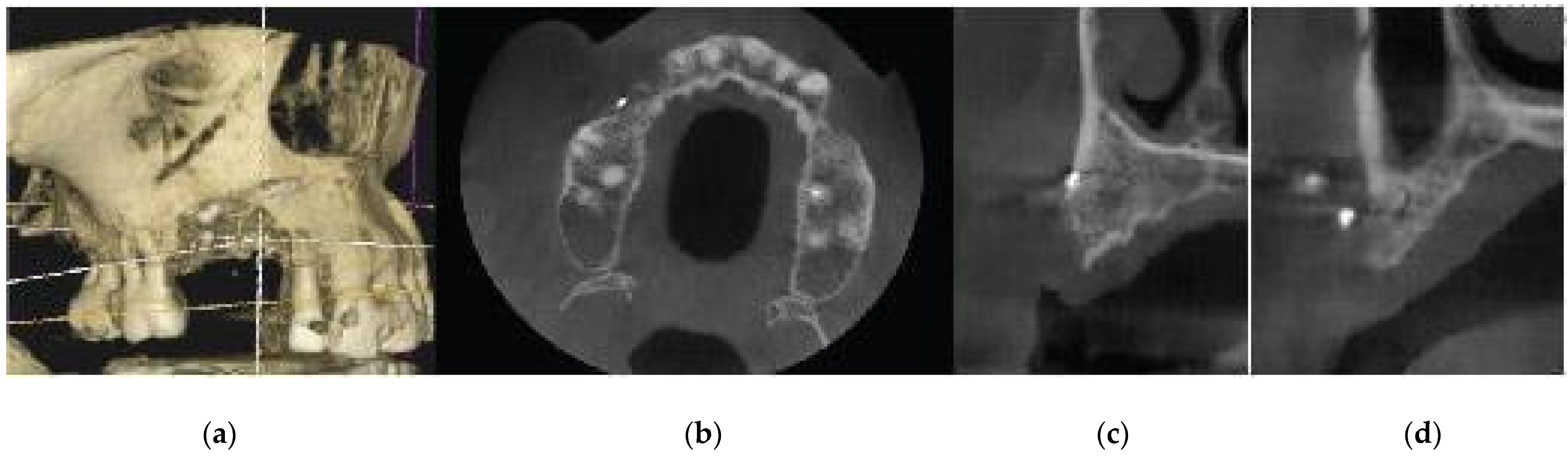
Figure 2.
Preop Clinical Situation – (a) Occlusal View, (b) Lateral view.
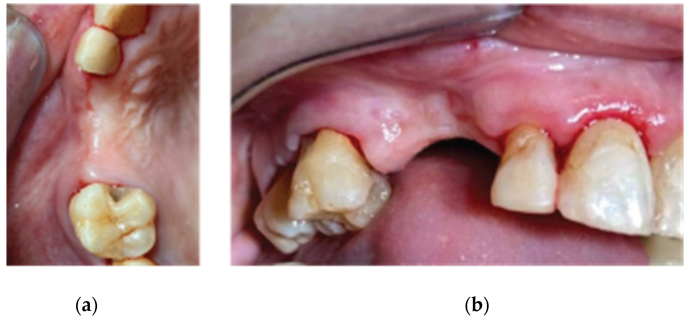
Figure 3.
Incision design – (a) Occlusal View, (b) Lateral View.
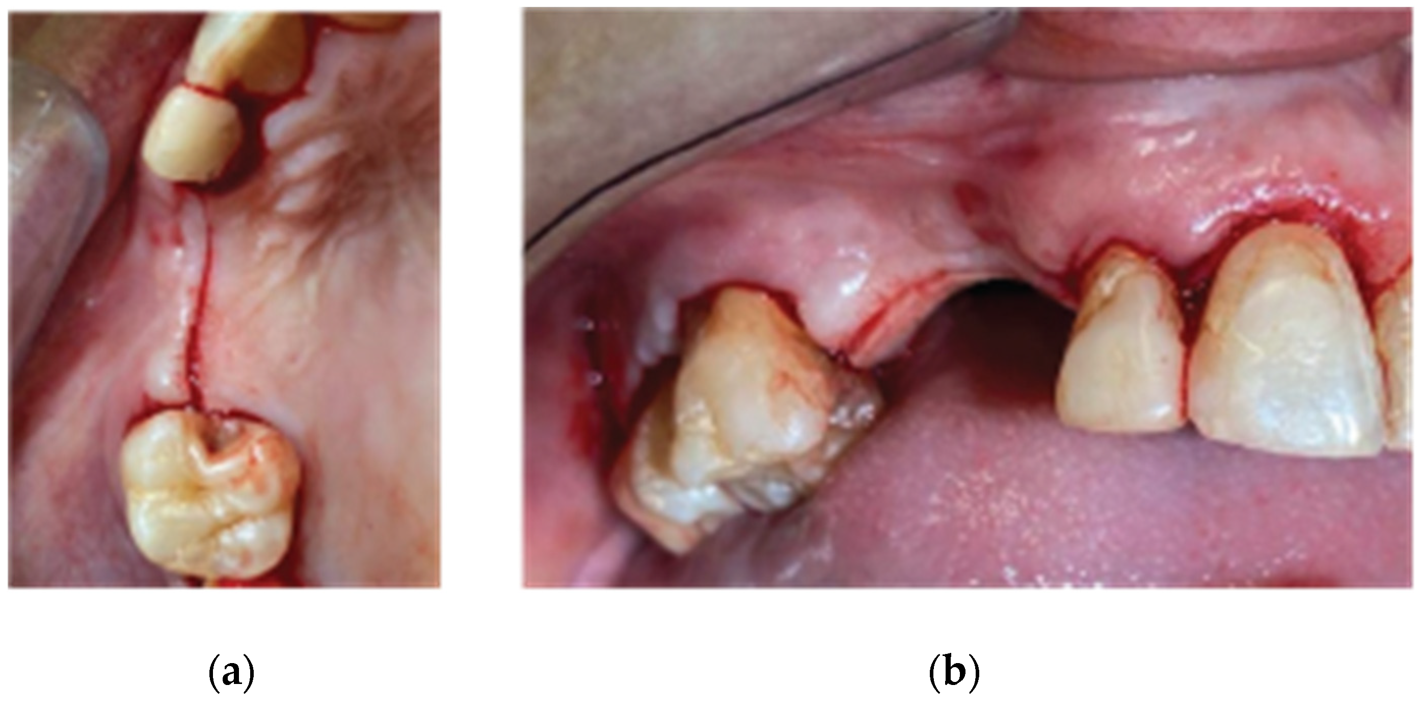
Figure 4.
3D Defect after Flap elevation – (a) Occlusal View, (b) Lateral View.
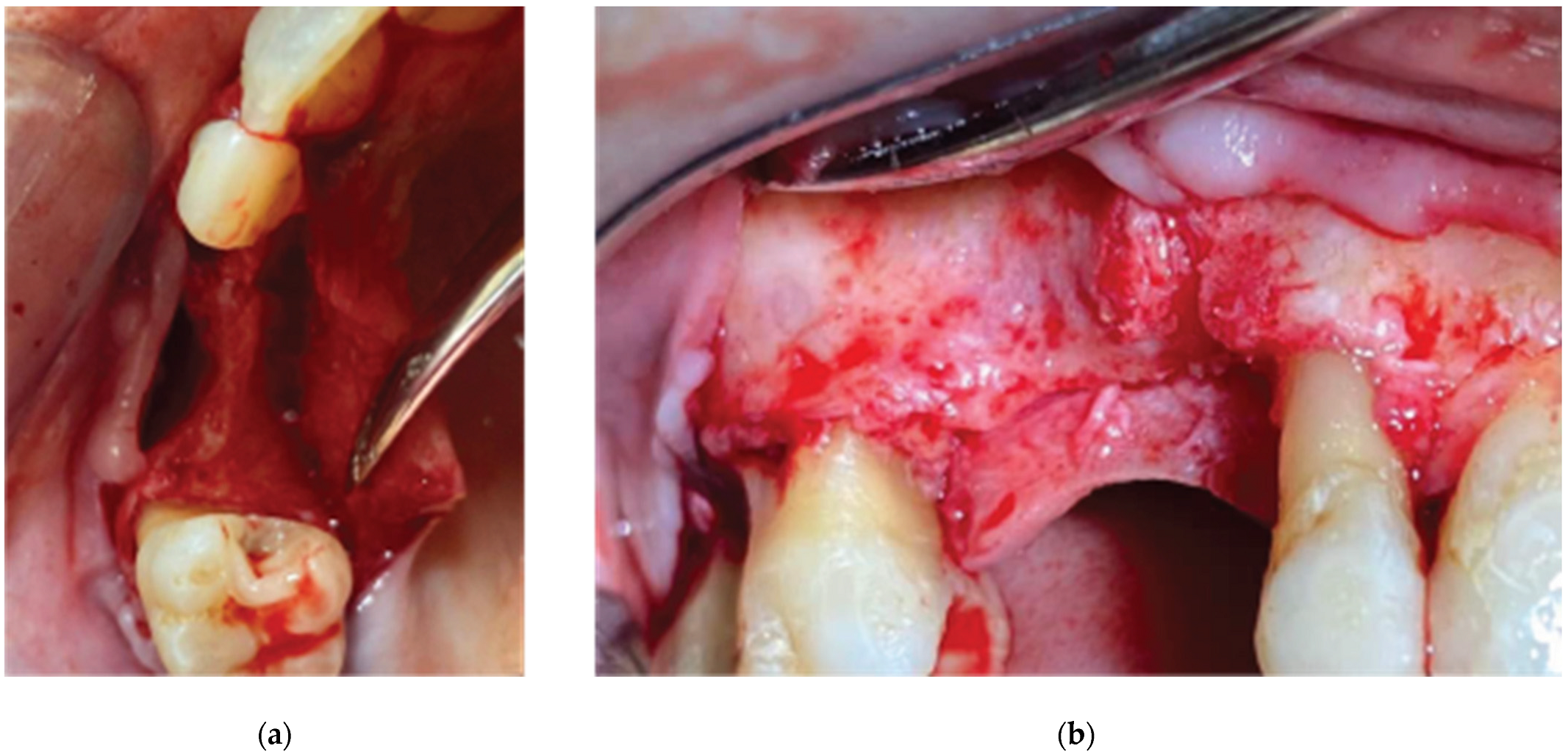
Figure 5.
Ridge Expansion and Protocol 1 Crestal Sinus lift with Versah drills –(a) Occlusal View, (b) Lateral View.
Figure 5.
Ridge Expansion and Protocol 1 Crestal Sinus lift with Versah drills –(a) Occlusal View, (b) Lateral View.
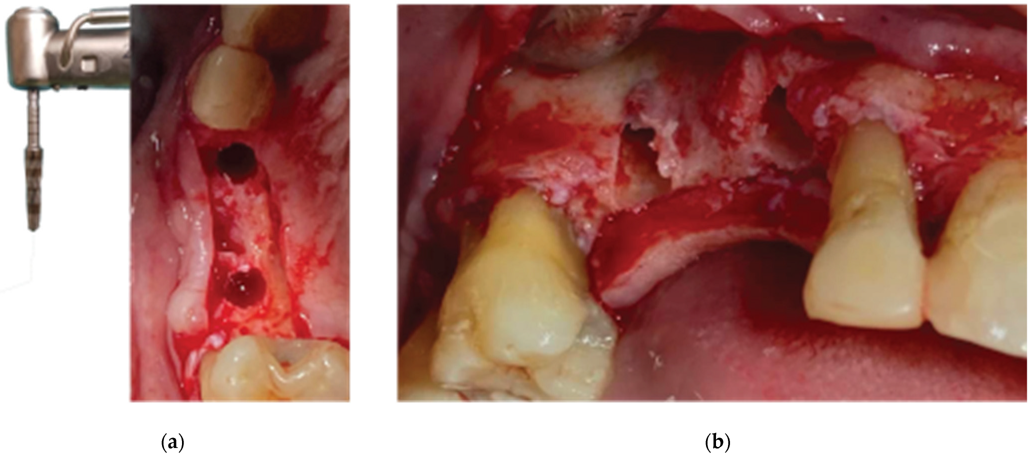
Figure 6.
Straumann SLA BLT Implant subcrestal placement – (a) Occlusal View, (b) Lateral View, (c) Checking buccal flap passivity prior to bone grafting.
Figure 6.
Straumann SLA BLT Implant subcrestal placement – (a) Occlusal View, (b) Lateral View, (c) Checking buccal flap passivity prior to bone grafting.
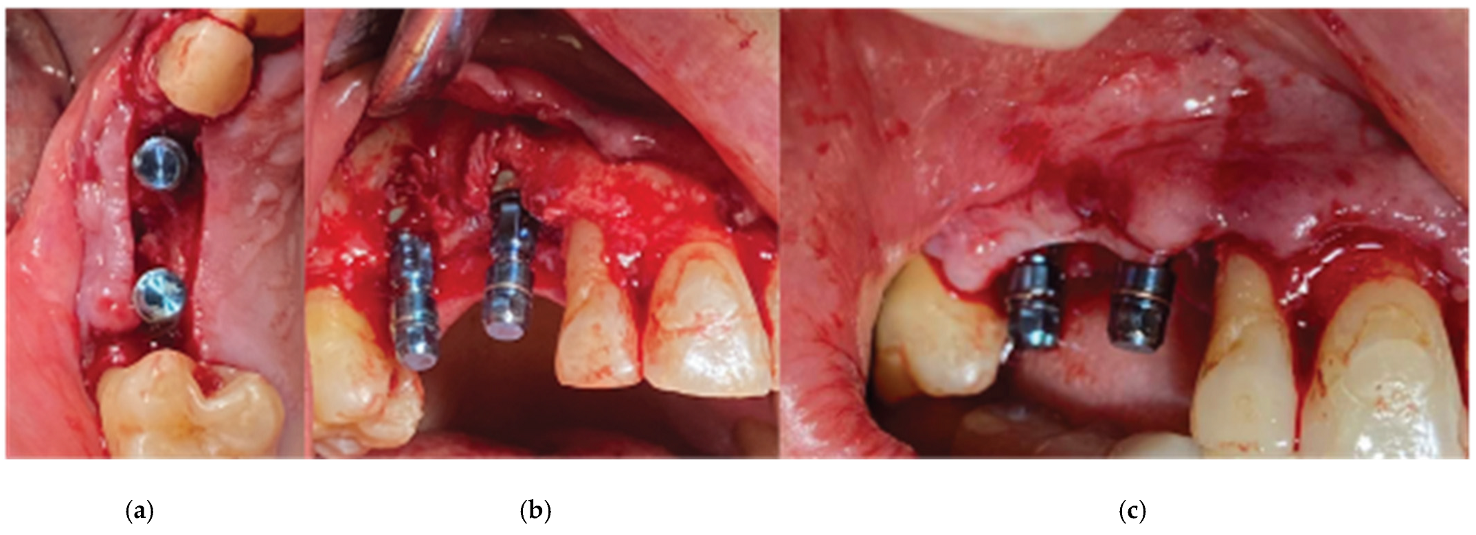
Figure 7.
Curved Cortical Lamina 35x35 Preparation.
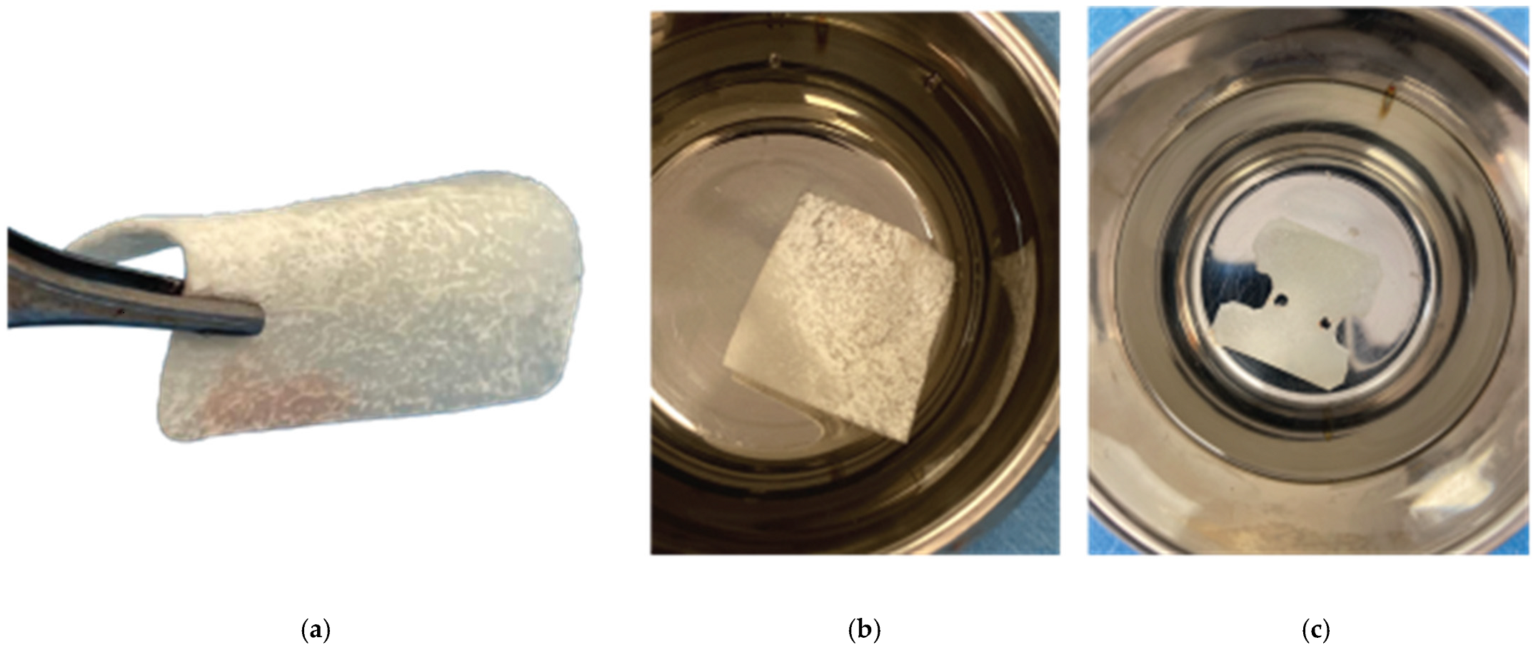
Figure 8.
Overgrafting with Genos Xenograft.
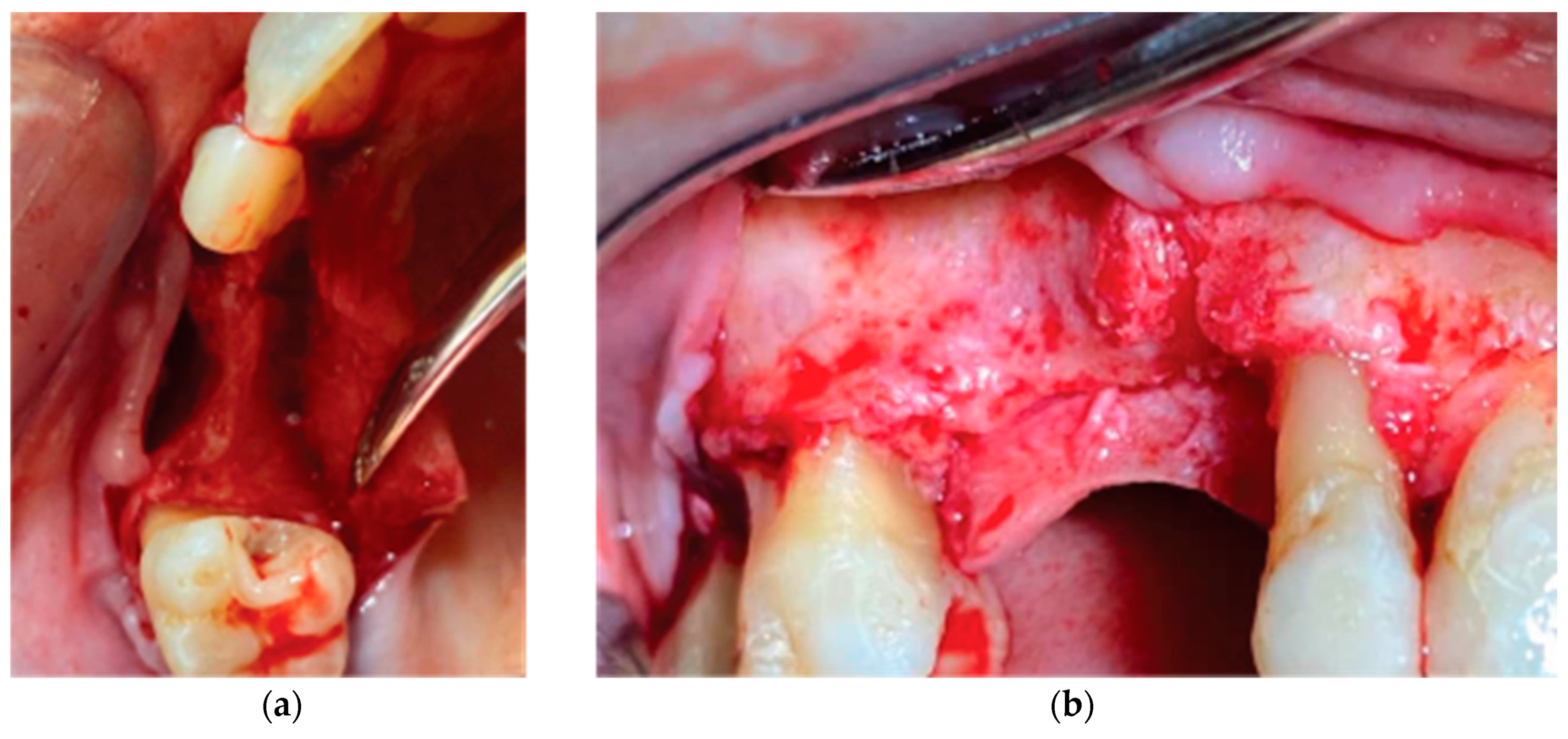
Figure 9.
Stock abutment-Lamina Compound in situ.
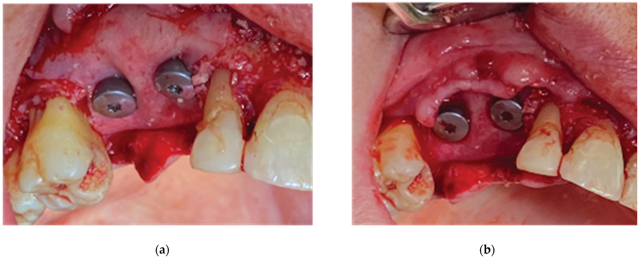
Figure 10.
Clinical Situation 2 Weeks Post op: (a) Lateral view with primary closure with the 2 layers of sutures, (b) Occlusal view with arrows revealing the palatal incision location.
Figure 10.
Clinical Situation 2 Weeks Post op: (a) Lateral view with primary closure with the 2 layers of sutures, (b) Occlusal view with arrows revealing the palatal incision location.
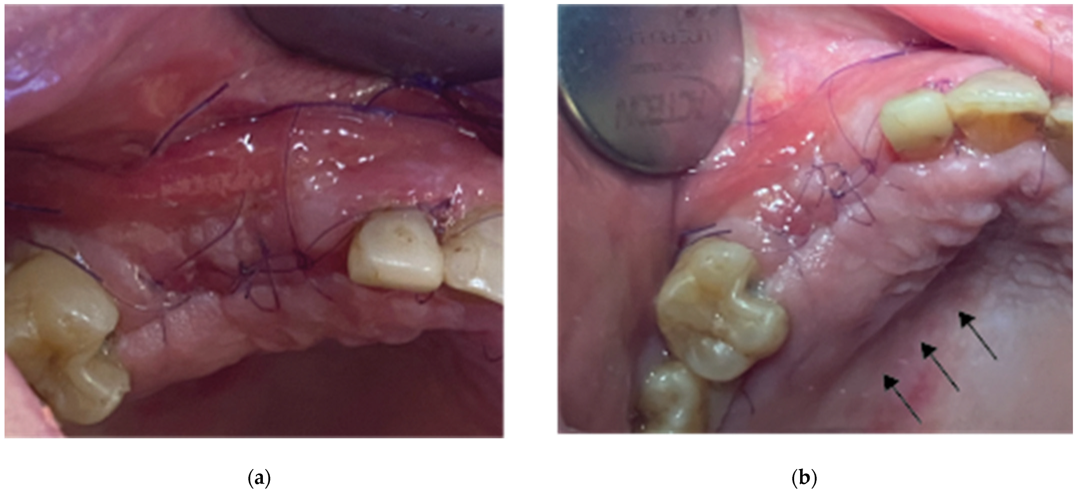
Figure 11.
Clinical Situation at 3 months post op – (a) Occlusal View, (b) Lateral View.
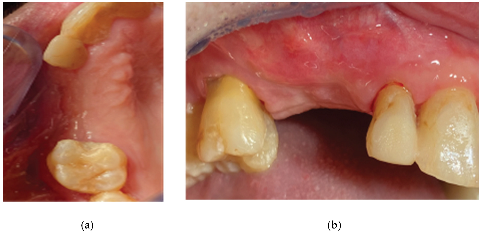
Figure 12.
Generation of customised abutments with the VPI Cervico System.
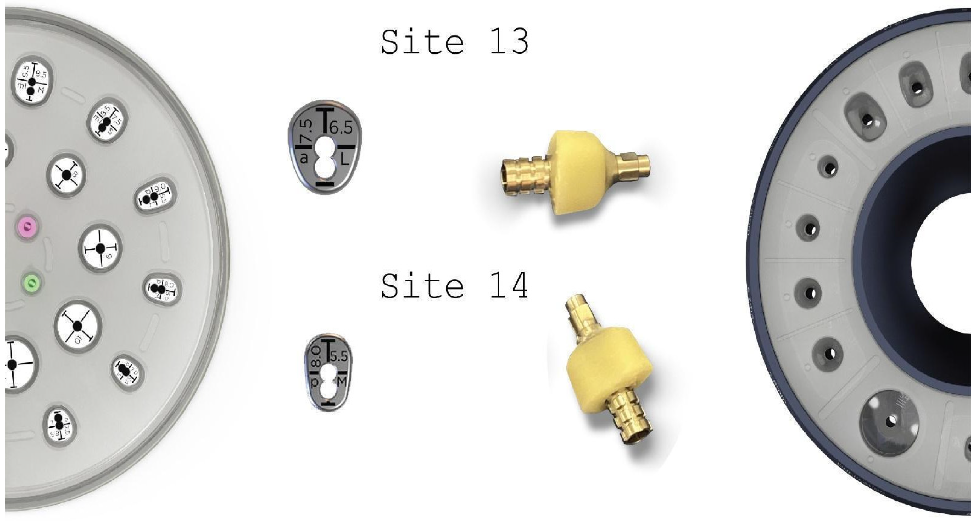
Figure 13.
Partial thickness incision – (a) Occlusal View, (b) Lateral View.
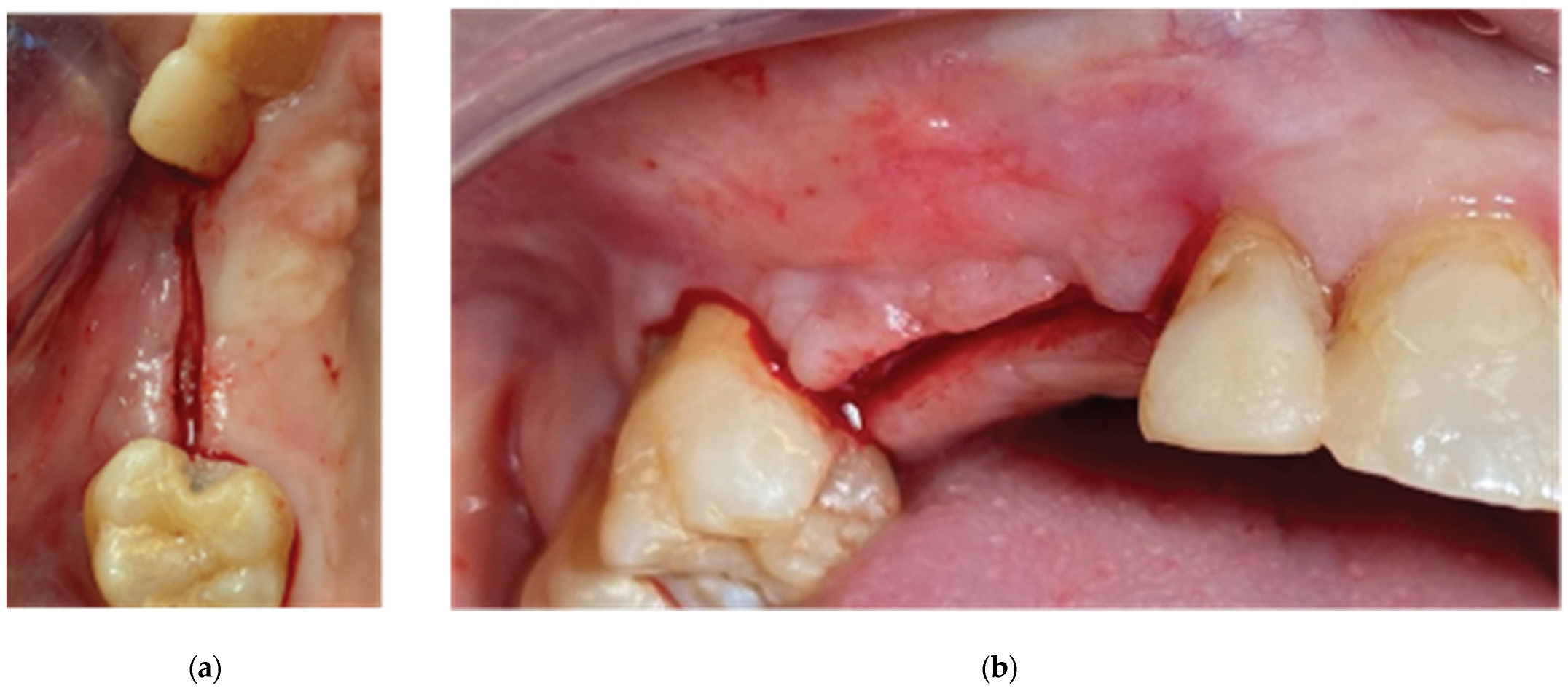
Figure 14.
Partial Thickness Flap and uncovering of the stock abutments’ platform.
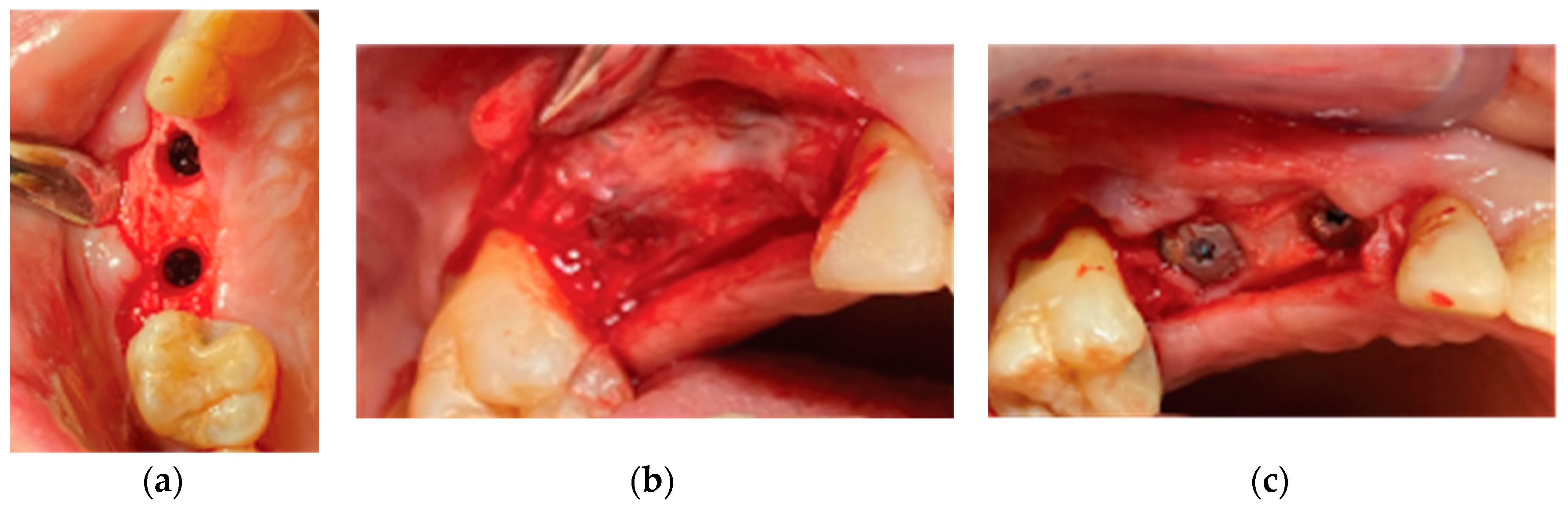
Figure 15.
Replacement of the stock abutments by VPI Crevice abutments and flap closure by adding collagen sponges within inter proximal areas.
Figure 15.
Replacement of the stock abutments by VPI Crevice abutments and flap closure by adding collagen sponges within inter proximal areas.
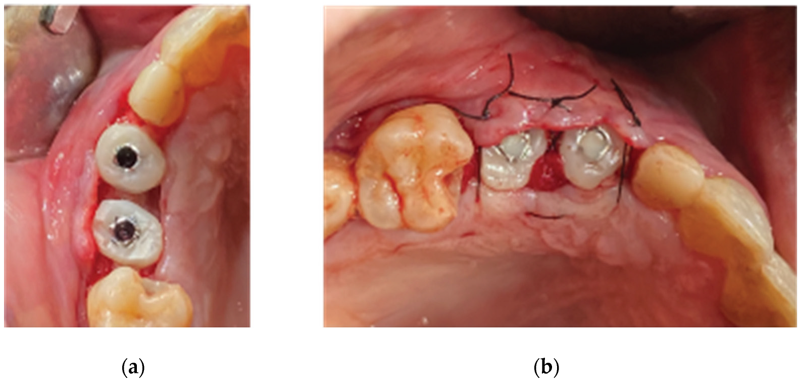
Figure 16.
Preop CBCT Situation – (a) 3d representation of the defect, (b).Axial mandibular image. (c) Cross sectional images sites 34, (d) site 35, (e) site 36.
Figure 16.
Preop CBCT Situation – (a) 3d representation of the defect, (b).Axial mandibular image. (c) Cross sectional images sites 34, (d) site 35, (e) site 36.
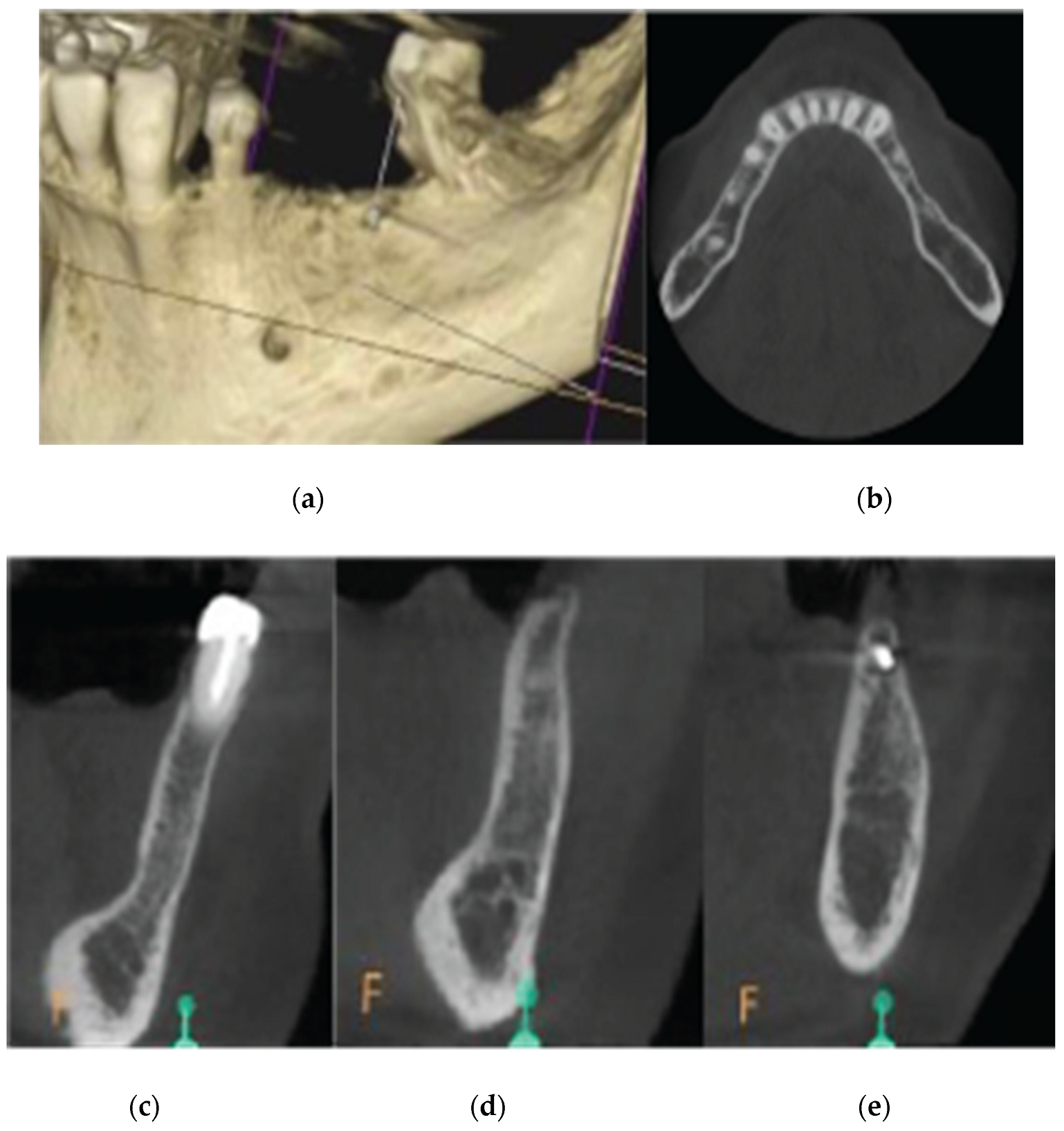
Figure 17.
Stage 1 surgical procedure -(a) Initial Situation, (b) Incision design and extraction of 34 tooth, (c) Thin alveolar ridge after flap elevation, (d) Stock abutment-Lamina compound following over grafting.
Figure 17.
Stage 1 surgical procedure -(a) Initial Situation, (b) Incision design and extraction of 34 tooth, (c) Thin alveolar ridge after flap elevation, (d) Stock abutment-Lamina compound following over grafting.
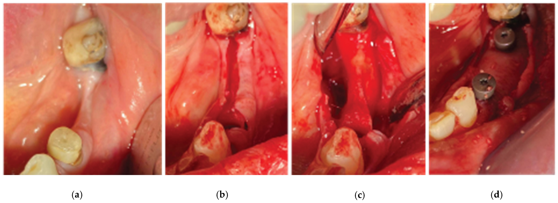
Figure 18.
Stage 2 surgical procedure – (a) Initial situation, (b) Emergence profiles after stock abutment removal, (c) Split thickness preparation.
Figure 18.
Stage 2 surgical procedure – (a) Initial situation, (b) Emergence profiles after stock abutment removal, (c) Split thickness preparation.
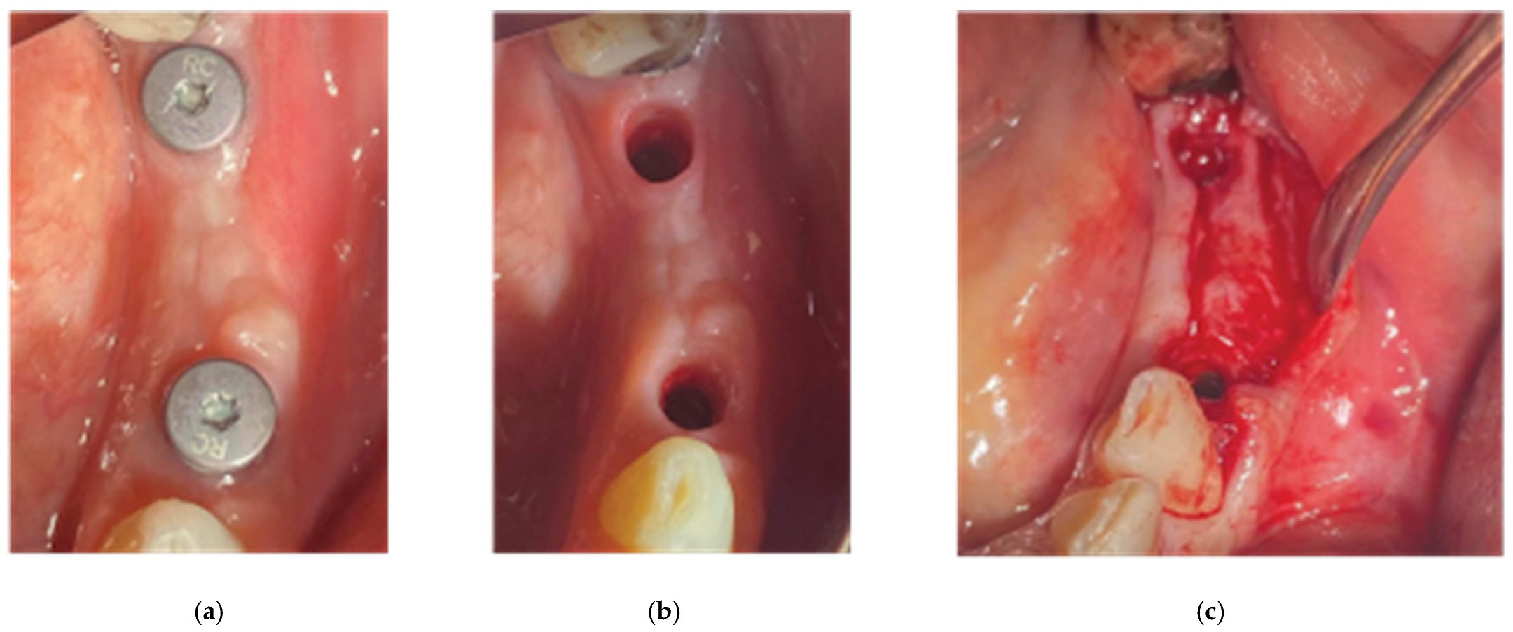
Figure 19.
Generation of a 3 profile fixture with VPI Cervico System and Periostick glass fibers.
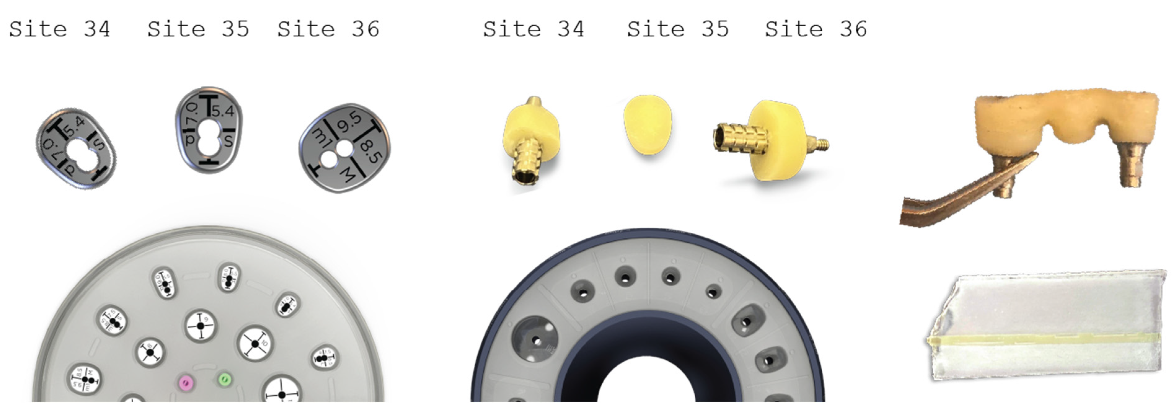
Figure 20.
The 3 unit profile fixture in situ and flap closure. Diode laser was used to reduce muscle pull.
Figure 20.
The 3 unit profile fixture in situ and flap closure. Diode laser was used to reduce muscle pull.
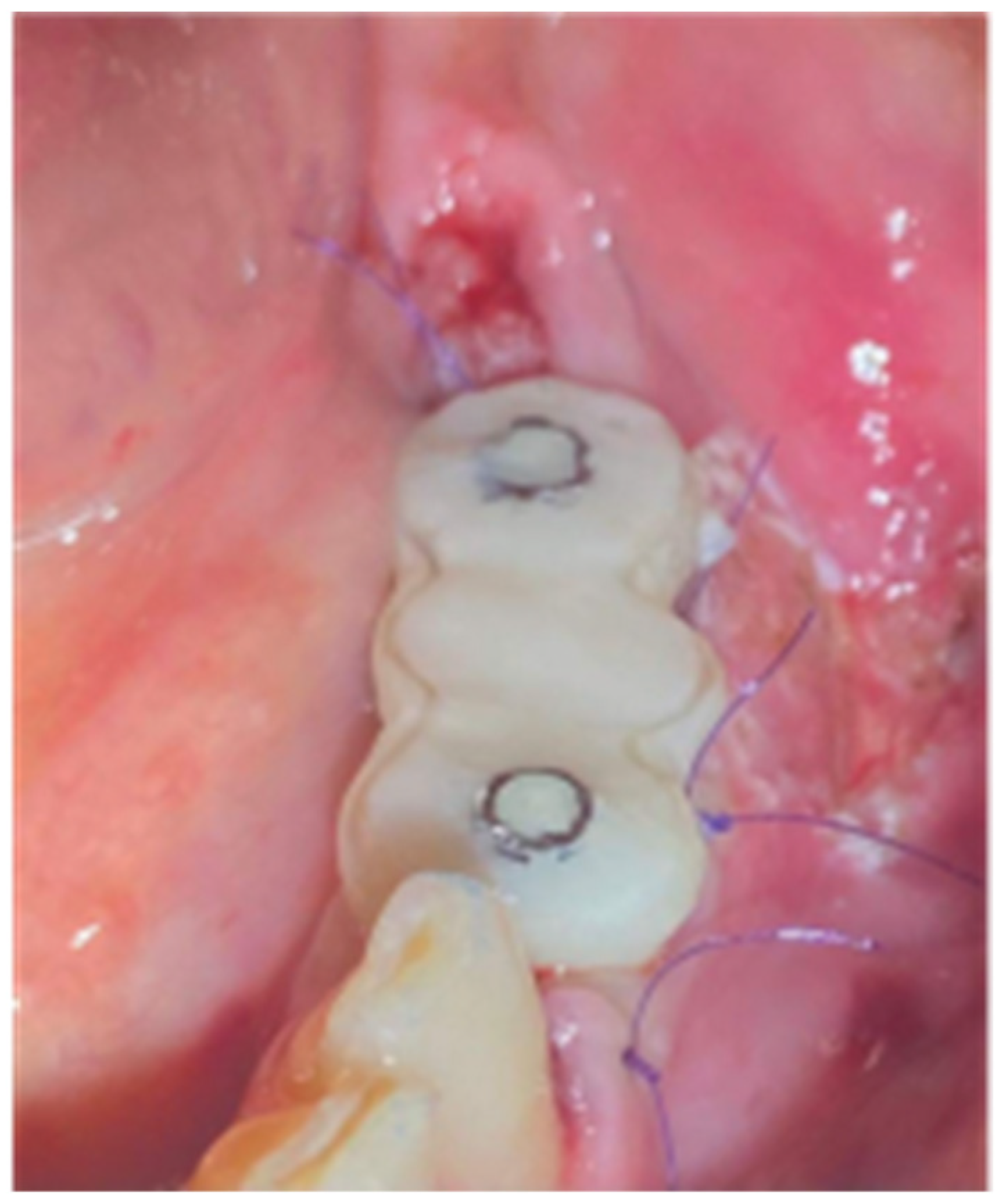
Figure 21.
(a) the T1 CBCT image of 13 site, (b) the superposed images T1-T2, (c) and the.post image T2, with measurment overlaid. (d) (e) (f) Similar set-up for 14 premolar site.
Figure 21.
(a) the T1 CBCT image of 13 site, (b) the superposed images T1-T2, (c) and the.post image T2, with measurment overlaid. (d) (e) (f) Similar set-up for 14 premolar site.
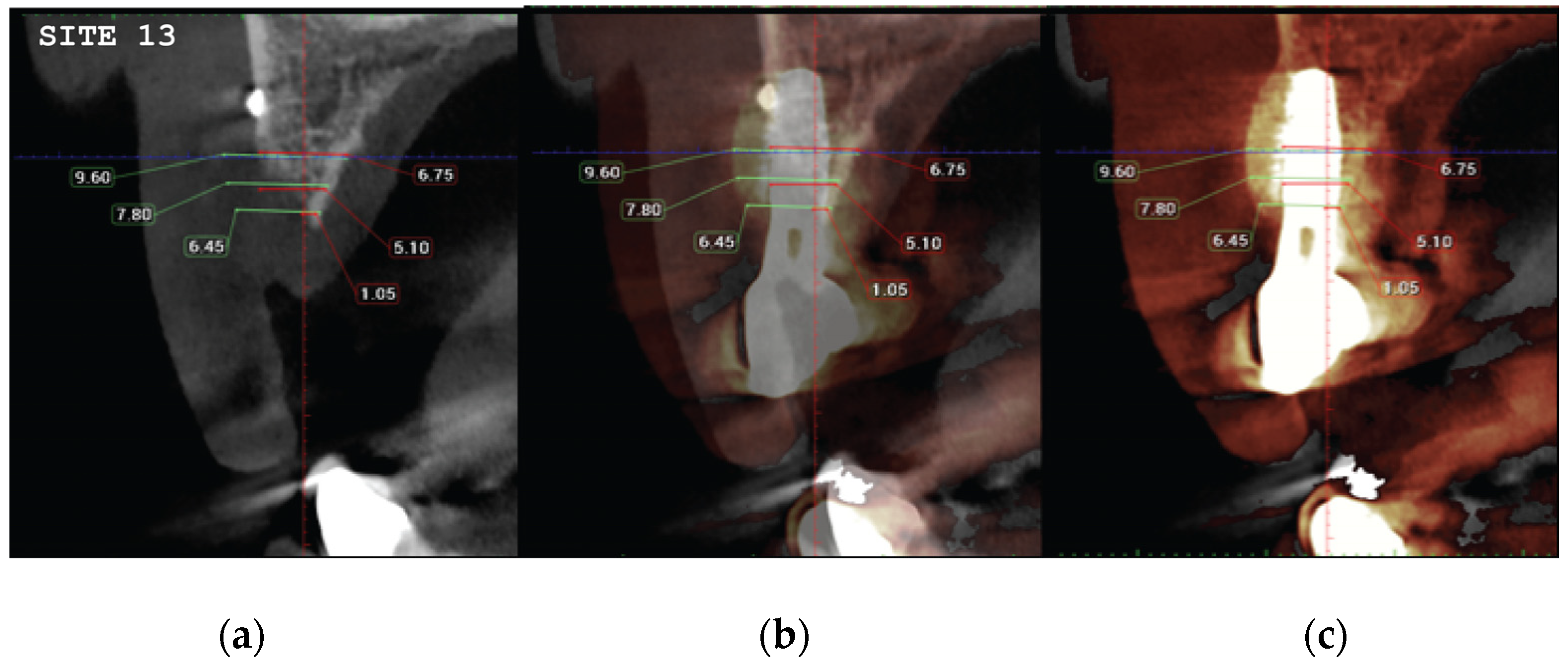
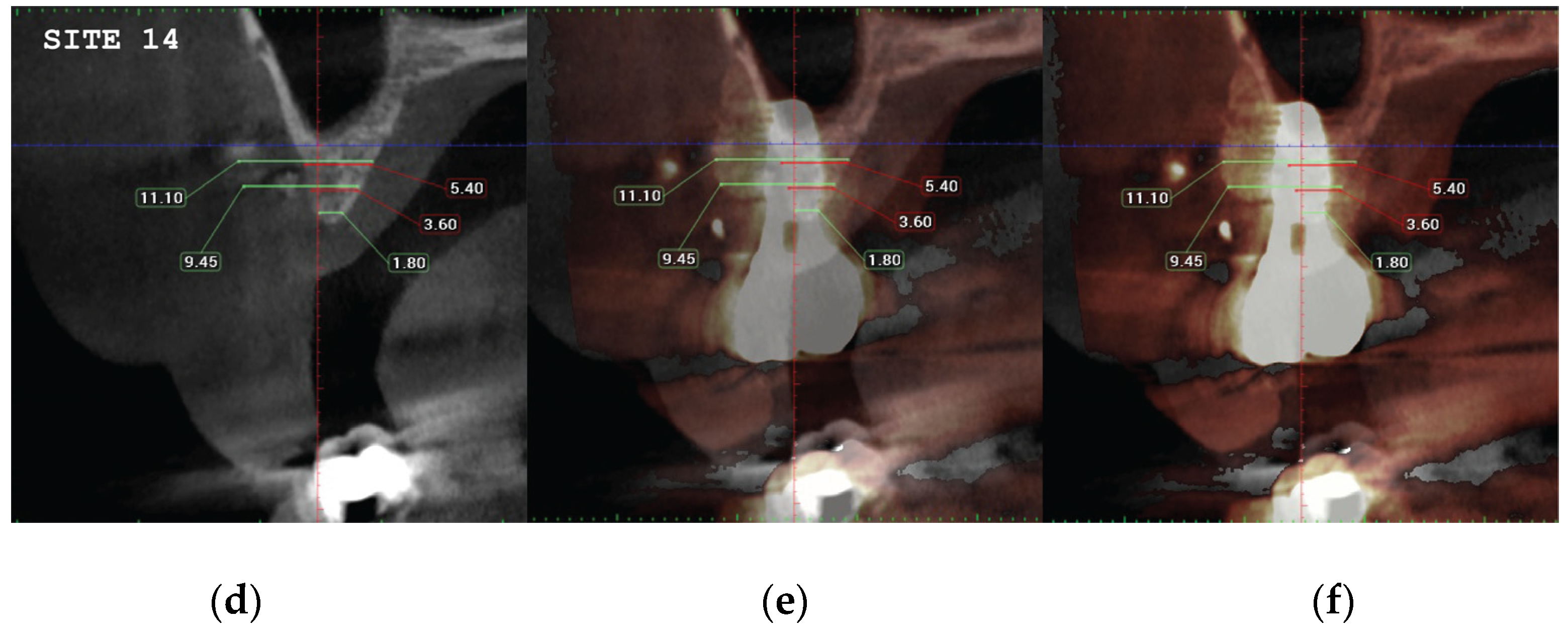
Figure 22.
(a) the T1 CBCT image of 34 site, (b) the superposed images T1-T2, (c) and the post image T2, with measurement overlaid. (d) the T1 CBCT image of 35 site, (e) the superposed images T1-T2, (f) and the post image T2, with measurement overlaid (g) (h) (i). Similar set-up for 36 molar site.
Figure 22.
(a) the T1 CBCT image of 34 site, (b) the superposed images T1-T2, (c) and the post image T2, with measurement overlaid. (d) the T1 CBCT image of 35 site, (e) the superposed images T1-T2, (f) and the post image T2, with measurement overlaid (g) (h) (i). Similar set-up for 36 molar site.
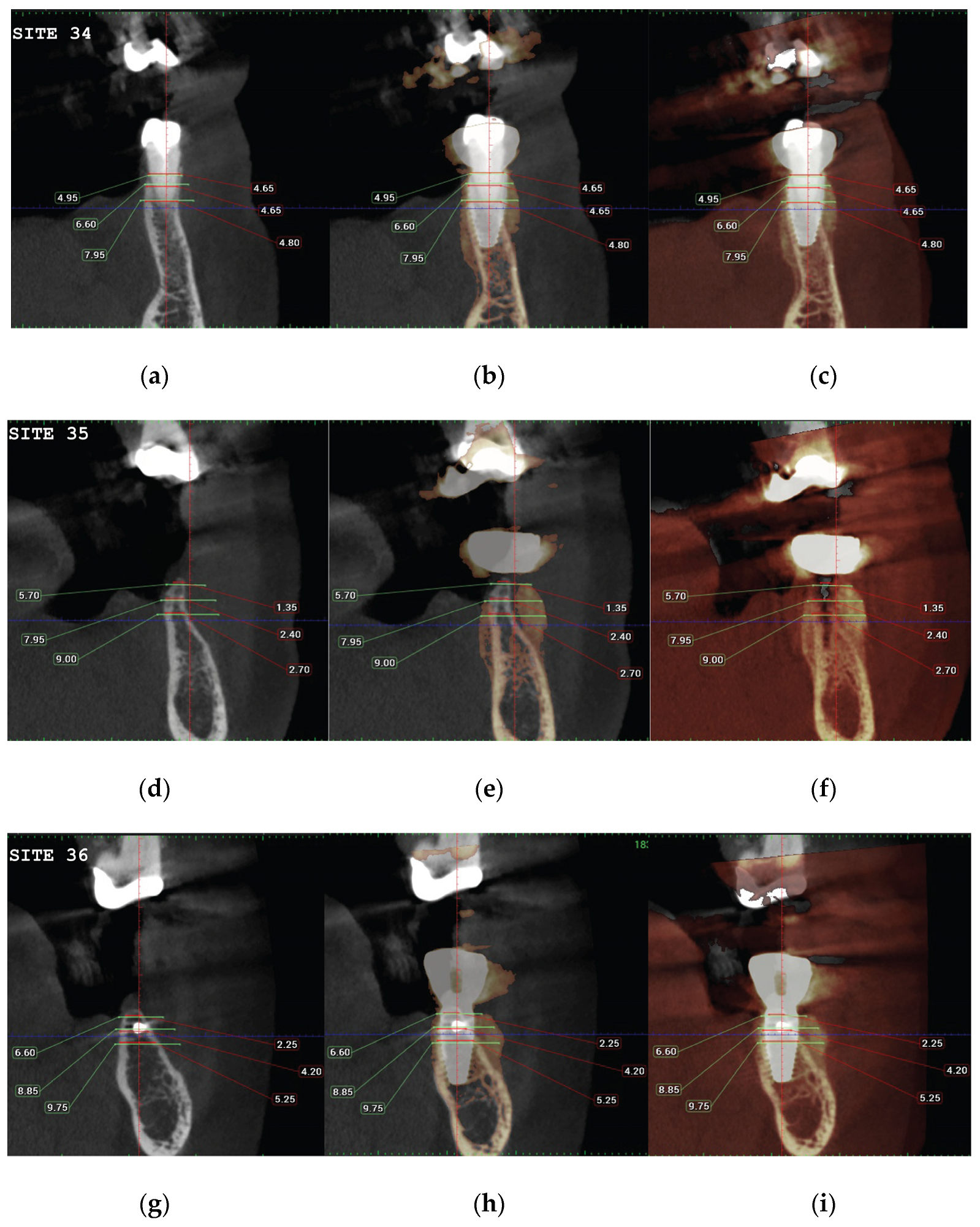
Figure 23.
A and B are the T2 images of both patients with manually segmented bone volume gain.
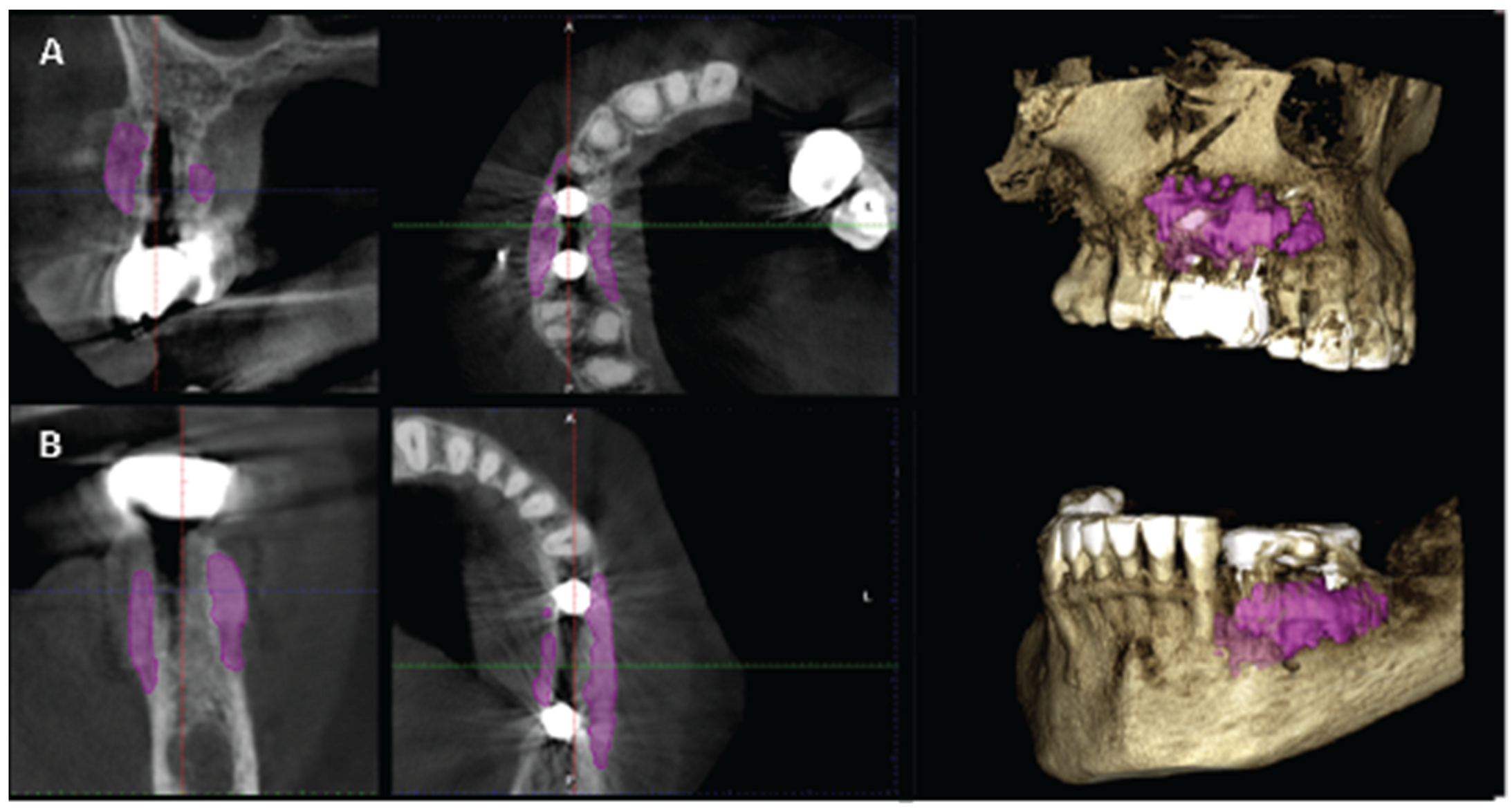
Figure 24.
Case 1 Final clinical result (a) Occlusal View,(b) Lateral View.
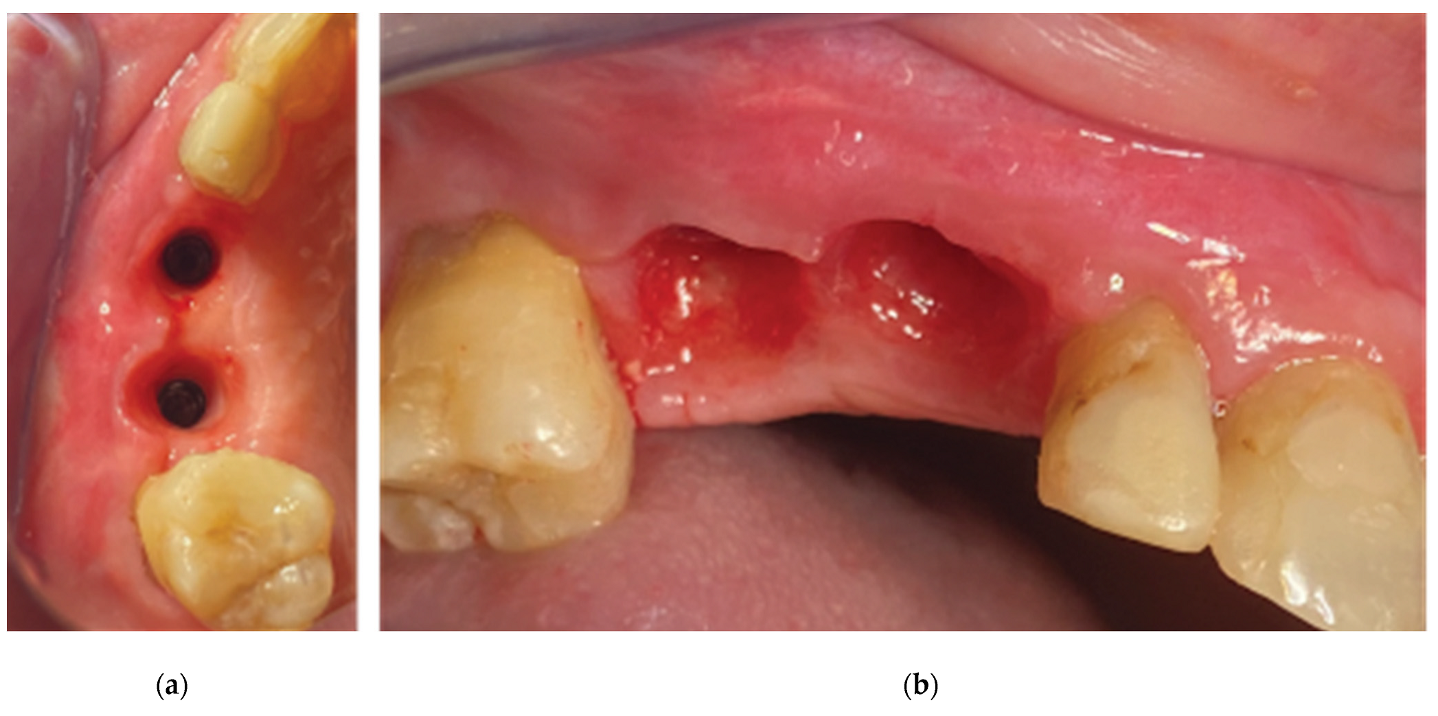
Figure 25.
Final clinical situation before and after removing the 3 profile unit fixture.
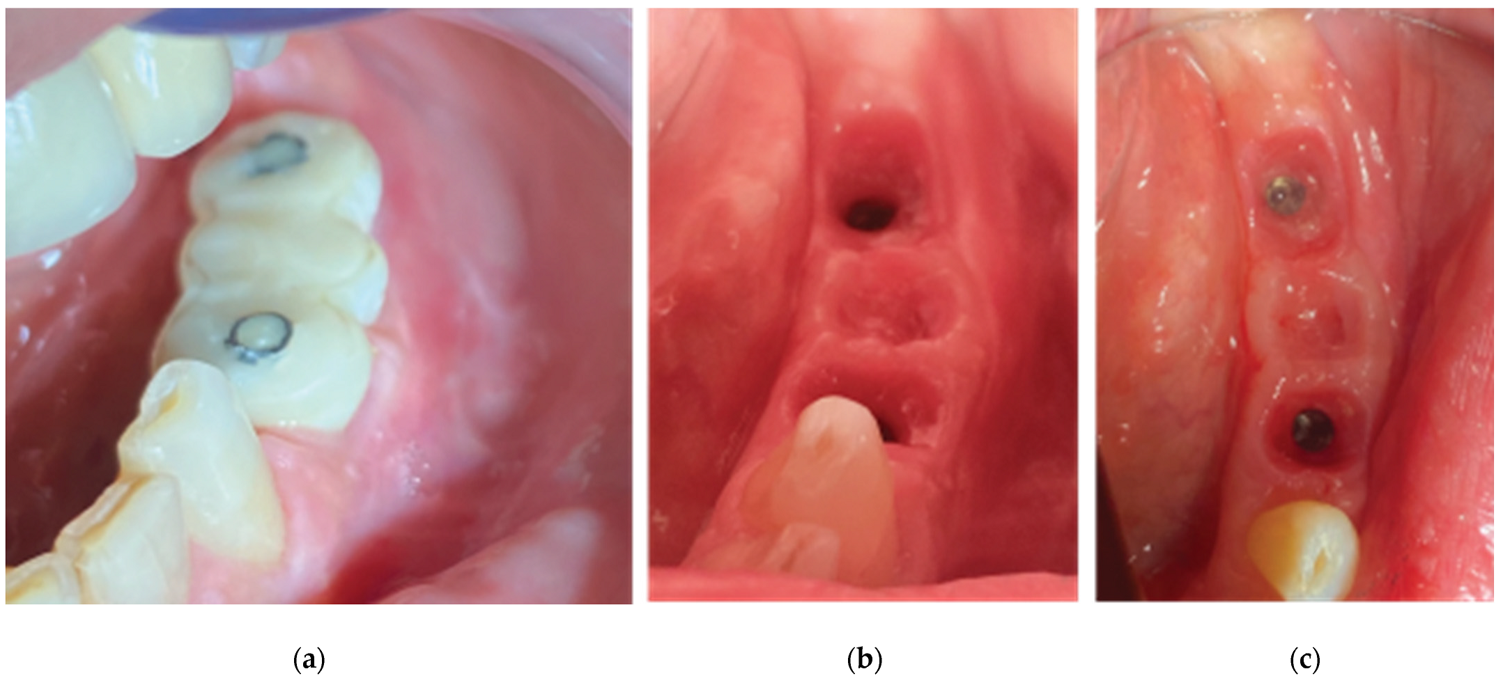
Figure 26.
(a) Supracrestal complex configuration for case 1 and height measurements at 6 perimetric areas-3 Vestibular (Mesial-MV, (b). Central-CV,Distal-DV) and 3 Palatal (Mesial-MP, Central-CP, Distal-DP).
Figure 26.
(a) Supracrestal complex configuration for case 1 and height measurements at 6 perimetric areas-3 Vestibular (Mesial-MV, (b). Central-CV,Distal-DV) and 3 Palatal (Mesial-MP, Central-CP, Distal-DP).
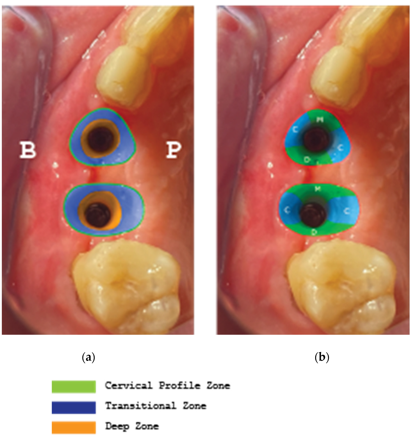
Figure 27.
Supracrestal complex configuration for case 2 and height measurements at 6 perimetric areas- 3 Buccal (Mesial-MB, Central-CB, Distal-DB) and 3 Lingual (Mesial-ML, Central-CL, Distal-DL).
Figure 27.
Supracrestal complex configuration for case 2 and height measurements at 6 perimetric areas- 3 Buccal (Mesial-MB, Central-CB, Distal-DB) and 3 Lingual (Mesial-ML, Central-CL, Distal-DL).
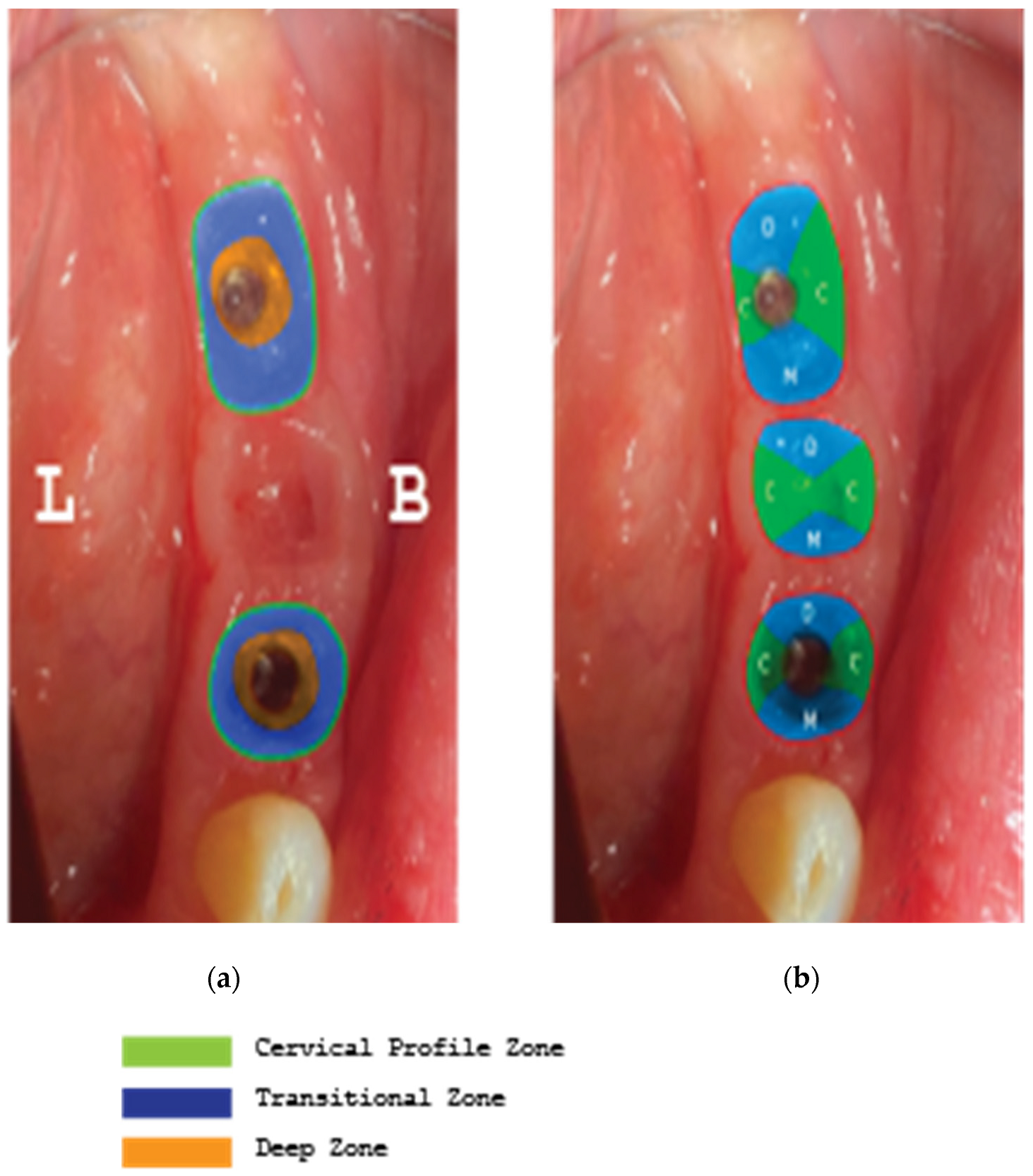
Figure 28.
Superposition of 3 Workflow charts for bone augmentation procedures with Straumann SLA implants: - Workflow 1: Usual ridge augmentation protocol with delayed implant placement - Workflow 2: Augmentation staged protocol with simultaneous implant placement - Workflow 3: Accelerated Poncho Lamina protocol.
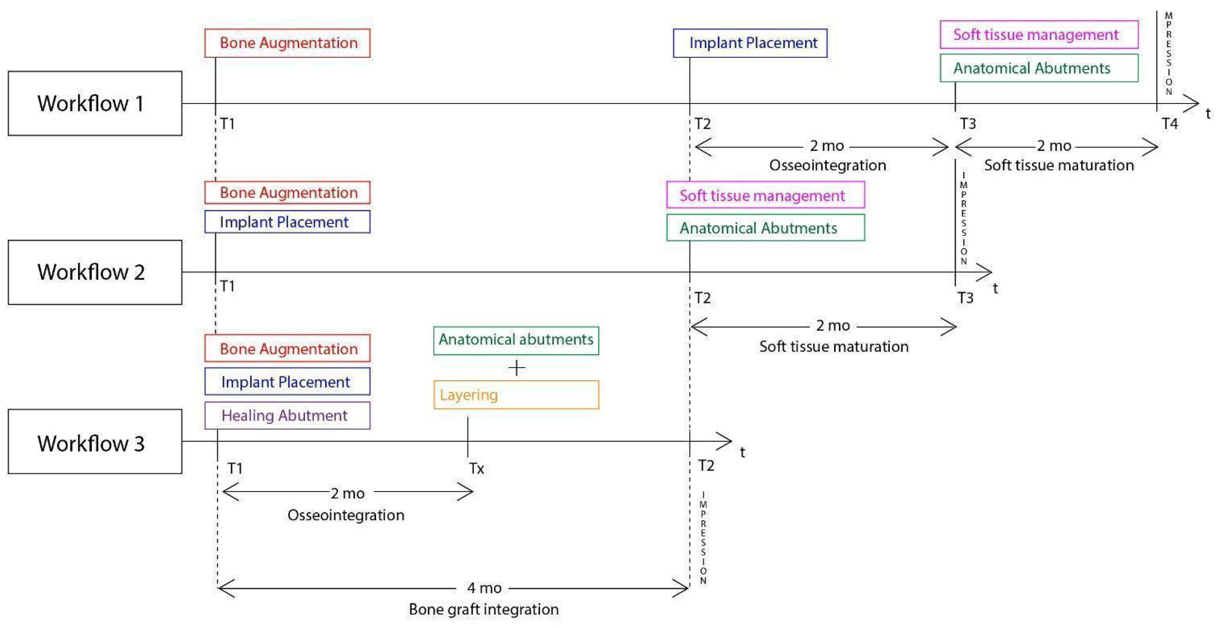
Figure 29.
The incisions used to ensure primary closure above the stock abutments for case 1.
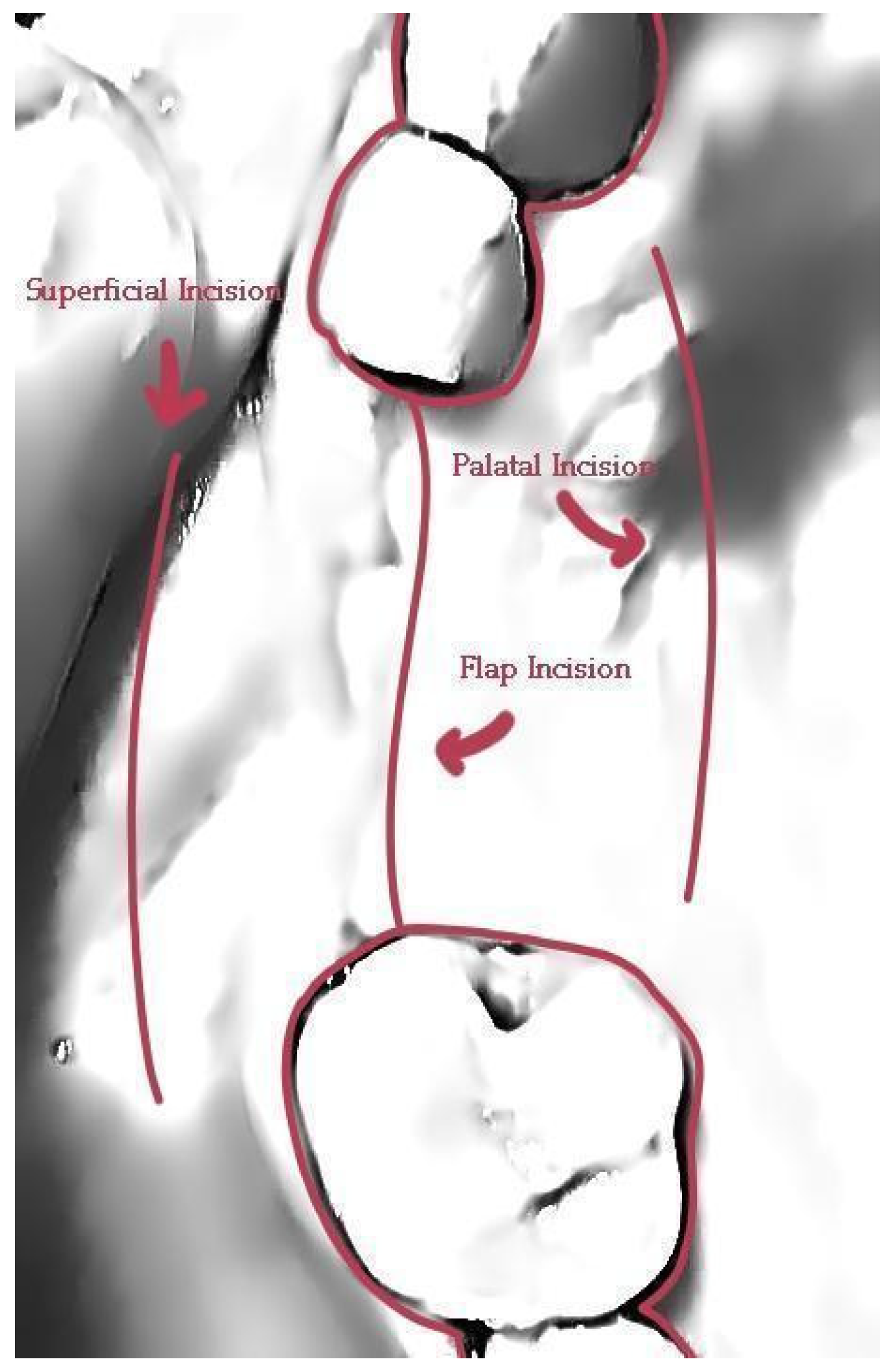
Figure 30.
Difference in Layering procedure initiation between Poncho lamina accelerated protocol when using SLA Active implants (Txx) compared to SLA (Tx).
Figure 30.
Difference in Layering procedure initiation between Poncho lamina accelerated protocol when using SLA Active implants (Txx) compared to SLA (Tx).
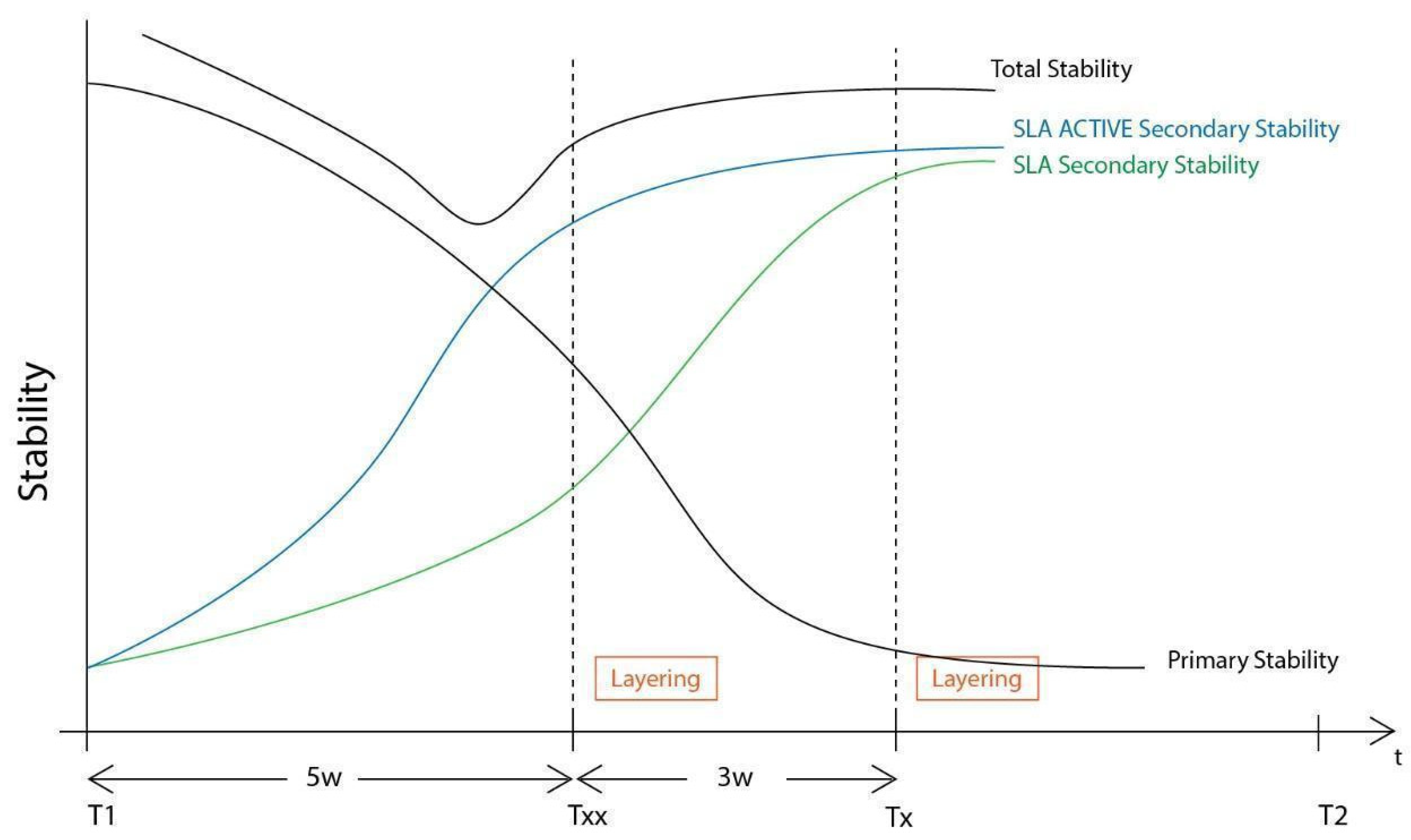
Figure 31.
Implant supracrestal complex and partial thickness preparation.
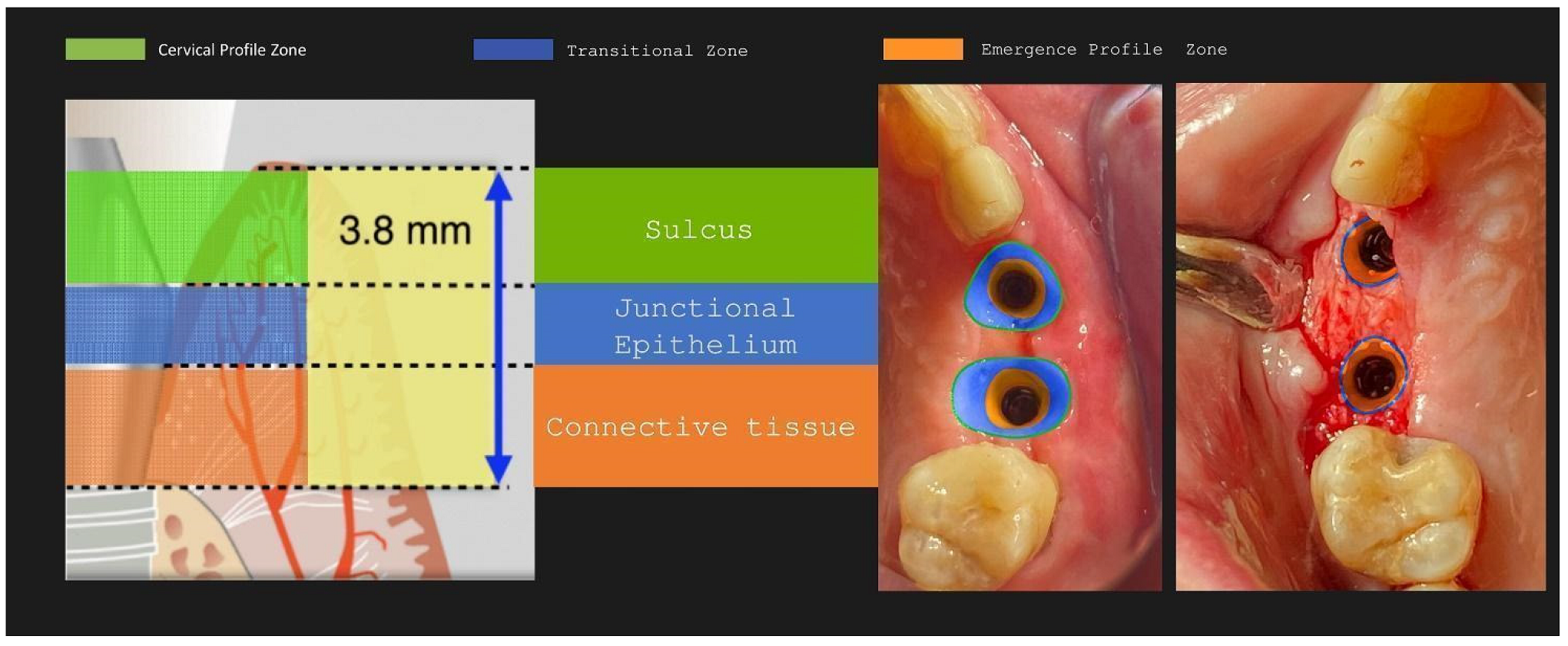
Figure 32.
Poncho Lamina accelerated protocol and Oxydative stress: from stage 1 to stage 2.

Disclaimer/Publisher’s Note: The statements, opinions and data contained in all publications are solely those of the individual author(s) and contributor(s) and not of MDPI and/or the editor(s). MDPI and/or the editor(s) disclaim responsibility for any injury to people or property resulting from any ideas, methods, instructions or products referred to in the content. |
© 2023 by the authors. Licensee MDPI, Basel, Switzerland. This article is an open access article distributed under the terms and conditions of the Creative Commons Attribution (CC BY) license (https://creativecommons.org/licenses/by/4.0/).
Copyright: This open access article is published under a Creative Commons CC BY 4.0 license, which permit the free download, distribution, and reuse, provided that the author and preprint are cited in any reuse.


