
Submitted:
19 September 2023
Posted:
20 September 2023
You are already at the latest version
Abstract
This paper presents an original method of additive manufacturing of cylindrical parts with variable circumference thickness, which allows the control of the deposition of molten material using an algorithm for decomposing the part geometry into volumetric elements with known dimensional configuration. In the absence of a post-processor capable of controlling additive manufacturing on a 5-axis numerical control machine, control of the deposition of molten material is done using parameterized programs, which can control both the feed speeds of the machine tool axes and the specific functions of the printing equipment. Additive manufacturing can make a positive contribution to sustainable development compared to traditional manufacturing technologies, thus making a positive contribution for a sustainable future. The aim of the work is to make it possible to 3D print parts with variable wall thickness using a CNC machining centre. To obtain the variable thickness layer we have implemented an original method of deposition with molten material (FDM), the coordination of the system composed of physical elements respectively programmable elements, is realized through control functions materialized in parameterized part programs, the generated outputs being the variable speed of the machine axes on a circular trajectory, the angular positioning, the filament advance.
Keywords:
additive manufacturing technologies
; sustainable development
; parametrized programs
; computer numerical control
; variable thickness deposition
; mathematical model
1. Introduction
Additive manufacturing is currently one of the fastest growing technologies by changing the production limits of highly complex geometric shapes.
These technologies are in full expansion today, as they can ensure fast, cheap and high-precision production of parts using 3D printing techniques, with arbitrary complexity of shapes (theoretically, from any material).
However, problems related to deformation and strength for products manufactured with these technologies remain unresolved [1,2,3,4,5,6,7,8,9,10]
Numerically controlled machine tools, industrial robots have a geometry and accuracy far superior to those of a 3D printer, and in the case of 5-axis machines or robots, parts of greater complexity than 3-axis ones can be produced, with significantly reduced time and material consumption. [11,12,13,14].
Printing equipment that uses plastic or metal material can be adapted to such machines, thus turning the machine into a hybrid machine, at a lower cost than purchasing a custom printing machine from some manufacturers. [15].
There are machines that can print parts out of plastic or metal and then be put on the same machine, generically called hybrid machines.
These machines are equipped with printing equipment as well as laying tools; however, the price of these machines may exceed the expectations of those who would like to implement them. [16,17,18].
There are companies that are currently researching and producing hybrid 3D printing machines that are used to manufacture parts for industries such as medical, automotive and aerospace that cannot be made through conventional processes. [19,20,21,22,23,24].
3D printers with filament deposition (Fused Deposition Material -FDM) with 3 axes are unable to process parts without supporting structures, because the printing direction is limited to the Z axis.
To solve this problem, hybrid 3D printing machines develop production processes of this type in two stages: in the first stage, the part is 3D printed layer by layer with enough additive material so that later, in the second stage, it is laid to the exact final size and shape of the part using a CNC machine tool. [25]
At the international level, research is performed in the field of 3D printing of variable wall thickness parts that has led to the intensive development of hybrid manufacturing machine tools, which combine laying operations with 3D printer operations in a single working environment.
At the moment there is not sufficient information on the existence of suitable, efficient, cost-effective hybrid machines capable of producing quality parts at low costs.
This is primarily due to their very high purchase and production price.
3D printing of parts with variable wall thickness can be considered an advanced technology that involves the use of hybrid machines for 5-axis printing.
This method can produce parts with a complex configuration involving variable wall thicknesses.
Hybrid printing machines allow the manufacture of unique parts, that are more complex than those produced on 3D printers, due to the fact that a hybrid machine has positioning accuracy, a working stroke and rigidity far superior to 3D printers. [26,27,28,29,30,31,32,33,34,35]
In order to 3D print on 5-axis hybrid machine tools, in the first phase the 3D model of the part is created and converted into a 3D printed extension program using a post-processor capable of generating codes (NC-code).
To control the movements of the moving parts of the machine: print head, translation and rotation axes, while the material is extruded to create the finished part. [36,37].
The hybrid manufacturing process combining FDM and Digital Light Processing-(DLP) for 3D printing of parts with variable wall thickness is an innovative technology that offers many advantages over traditional manufacturing technologies through the ability to produce parts with complex geometries with a high level of precision, making it possible to manufacture products with a minimal material waste compared to traditional (subtractive) manufacturing technologies make it an attractive option for different fields. [38,39].
Sustainability in additive manufacturing carried out on hybrid machine tools in 5 axes, refers to: the use of eco-friendly materials, recyclability, reuse of recyclable materials, establishment of waste collection and reintroduction processes in the production cycle.
Additive manufacturing allows for the precise deposition of materials, reducing waste to a minimum compared to traditional manufacturing methods. [40,41]
When additive manufacturing is carried out on a 5-axis CNC machine tool, the print head has the ability to move in several directions (3 translations and 2 rotations), which allows the production of parts with complex geometries, thus creating the premise of eliminating supports or supporting structures.
In this way the process is detached, qualitatively and quantitatively from 3-axis printing, which leads to a reduction in waste and increased sustainability in additive manufacturing. [42,43]
By integrating these sustainability considerations into the additive manufacturing process carried out on 5-axis CNC machine tools, manufacturers can: minimize waste quantity, reduce energy consumption and choose eco-friendly materials (bio-degradable, such as Polylactic Acid-PLA, polymer blends, lignin from bio-mass that can be manufactured from renewable sources) with a lower environmental impact, contributing positively to a sustainable future. [44,45,46]
The present work presents an original method of 3D printing of cylindrical parts with variable thickness per circumference.
The method allows the control of the forward speeds of the machine tool axes as well as the specific functions of controlling the motion and temperature of the filament involving an algorithm for decomposing the geometry of the part into volumetric elements with known dimensional configuration.
This method has been used to develop CNC machine tools, to adapt printing equipment to these machines and to optimize manufacturing and production costs in additive manufacturing, thus ensuring the sustainability of the technology.
2. Materials and Methods
2.1. Study on the deposition of layers with variable height
The aim of the work is to make it possible to 3D print parts with variable wall thickness using a CNC machining centre.
To obtain the variable thickness layer we implemented an original meth-od of depositing with molten material (FDM), the coordination of the system composed of physical elements respectively programmable elements, is achieved by the control functions materialized in parameterized part programs, the output generated being the variable speed of the machine axes on a circular trajectory, angular positioning, filament advance [47].
In order to obtain a part that does not show unevenness after depositing, certain settings of the printing technology must be used, such as the use of equipment capable of printing in more than 3 axes, the orientation of the deposited material layers, the thickness of the layer, the melting temperature, etc.
2.2. Example of printing technologies for thin-walled parts
Fused Filament Fabrication (FFF) on 3D printers with 3-axis in a printing configuration as shown in Figure 1 (a), and a new Curved Layer Filament Printing (CLFF) process that is used to improve the quality of the layer deposited as shown in Figure 1 (b) [48,49,50].
The deposition of curved profile material as shown Figure 2 (a) is carried out using the multi-axis 3D printers, which have the possibility to rotate the extruder or worktable on industrial robots as shown Figure 2 (b).
During orientation-based deposition, this can be achieved by both the nozzle and the mass of the printing machine shown in Figure 3. Thus, during material deposition, the extruded thickness of the filament will have variable values, depending on the design requirements, so that the final shape of the part conforms to the designed one.
The post-processors required to printing parts with variable thicknesses of the deposited layers are constantly being developed, making it possible to obtain parts with complex configurations due to the orientation of the deposited layers. In addition, they must have mechanical and surface properties that meet design requirements, parts that can be printed in a shorter time comparable to traditional technologies, all with reduced material consumption.
3D printing using 5-axis machine tools is a favorable method for obtaining thin-walled parts, manufacturing time and material consumption being massively reduced, but it is imperative to solve post-processing problems, avoiding possible collisions between the nozzle and the printed part.
Printing of thin-walled parts, realized with a robot without printing supports. These supports, which are used in the case of classical printing (3-axis), require a long manufacturing time, and if they are made of another material (e.g. water-soluble-PVA), two printing devices (heads) are needed, one for the base material, one for the support material.
2.3. Study on printing with variable height layer
In the case of conventional additive machining, where the deposited layers are of constant width (section planes are parallel), a simple volumetric flow model of the material flow through the deposition nozzle can be developed.
The mass flow through a nozzle is related to the pressure drop, nozzle geometry, melting temperature and viscosity of the material.
Assuming that all physical conditions are met, the melting capacity of the material is within the prescribed limits, the material flow Q can be expressed as a function of the filament feed rate v_e and the filament diameter d_i shown in Figure 4 and equation 1.
Figure 4 shows the axis notations have been chosen to follow the CNC machine axis notation.
The E axis is parallel to the Y axis and in the opposite direction indicates the direction of the filament movement. This is example 1 of an equation:
This flow ensures the deposition of a layer whose section can be approximated with a central rectangle and two semicircular areas shown in Figure 4, and the advance velocity in the direction of deposition is noted with v_x 2 as example 2 of an equation:
(2)
Since they represent the same flow, Equation 1 and Equation 2 can be equated to obtain the relationship between the filament forward velocity and the deposition velocity (displacement velocity on the X axis) as is example 3 of an equation:
In the case of variable layer thickness deposition, the material flow is no longer constant, but will have to be correlated with the change in layer thickness.
In this way, the filament feed rate v_e will have to be correlated with both the change in deposited layer thickness ∆h and the deposition rate v_x, with the notations shown in Figure 5.
In this figure, h_0 is the initial height of the layer and v_y is the nozzle advance velocity in the vertical direction. This velocity must also be correlated with the feed rate of deposition and filament. The correlation between vertical and horizontal feed rates is shown in example 4-7 of an equation, assuming that f(x) is linear as example 4 of an equation:
The notations used in relationships 4 - 8 are explained in the diagram of Figure 6.
The advance speed of the nozzle v_y is obtained by deriving equation 6 as a function of time
In this case, the flow rate required for deposition of the layer expressed in equation 9 and the flow rate provided by the filament advancement expressed as example 10 of an equation must be equal.
By equating the two relations we obtain the correlation between advance rate of filament and the deposition as example 11 of an equation.
This means that the filament feed rate must be provided by a programmable actuator and that it varies according to the variation of the filament supply speed f(x), in this particular case f(x) = mx.
One problem with this solution is that the filament feed rate is limited due to the drive system and also due to the limits of the filament melt speed.
In this case, one can try to apply a constant filament feed rate but a variable deposition rate as example 12 of an equation.
2.4. Study of the deposition for a geometric configuration/shape
In the additive manufacturing process on a CNC horizontal machining center it is necessary to be equipped with rotation axes so that the deposition section is rotated.
The study of deposition for a geometric configuration was carried out in order to print it on a TMA-AL-550 horizontal machining center with CNC shown in Figure 7, which is in the equipment of the University of Oradea.
Thus, at the beginning of the printing process, the base of the cylinder is made in a horizontal plane (parallel to section A1B1) and the layers are deposited in parallel.
For the curved portion of the cylinders (starting with section A2B1), the method can be applied by rotating around the center of curvature O2 in α steps, successively depositing layers of varying width along the circular section from a width of BnBn+1 to widths of AnAn+1 shown in Figure 8.
After making the last section on the curved portion, the piece will be rotated 90° from the original position and the deposition of the parallel layers will be resumed, and Figure 9 shows the notations for the geometric elements of the circular section with variable width that are used in example 13-22 of an equation.
The expression for the layer thickness can be obtained by determining the intersection of the cylinder with a plane inclined at an angle α to the base plane XO_1Z.
The parametric equations of a cylinder are given as example 13 and 14 of an equation:
The equation of the plane is given as example 15 of an equation:
The normal vector to the plane is: , and
According to the scheme shown in Figure 9, the expressions for the coefficients of a plane equation that are given as example 16 and 17 of an equation:
Substituting into example 15 of equation, we obtain the expression for the thickness of deposited layer as example 18 - 21 of an equation:
Then, substituting the expression of the variable x into example 13 of an equation, we obtain as example 22 of an equation:
By deriving example 22 of an equation the nozzle advance speed is obtained as example 23 of an equation:
And noting with v_y=dy/dt; velocity on the Y axis and with ω=dθ/dt the angular velocity, the relationship between angular velocity and Y-axis velocity results as example 24 of an equation:
or expressing the angular velocity as a function of the tangential velocity v_1 (ω=v_1/r_1) and the velocities on the X and Z axes as well as the tangential speed results in the velocity expressions on the three coordinate axes as example 25 of an equation:
From the example 25 of an equation it can be observed that the velocity v_y depends linearly on the v_x velocity, the angle α being constant (the rotational increment around the center O_2) as example 26 of an equation:
The advance speed of the filament v is obtained by replacing in example 27 of an equation the expression for the function f(x), (given explicitly in example 4, with f(x) = y in example 21) as example 27 of an equation:
Similarly, it can be shown that for any trajectory, the relationship between the rate of thickness increase for the layer depends linearly with the rate of advance deposition.
2.5. Programming of the TMA-AL-550 hybrid machine
In order to achieve 3D printing of parts with variable wall thickness using a TMA-AL-550 horizontal machining center, a fixed head printer in spindle was assembled to create a hybrid machine.
The hybrid machine TMA-AL-550 shown in Figure 10, which is located at the University of Oradea, is a horizontal machining center with CNC and the control equipment from FANUC series 310i-A5 with drives, motors and servo motors, equipped with 5 axes that work simultaneously X, Y, Z, B, C, axes B and C are rotational 4x90°.
2.6. Technical parameters for printing on the TMA-AL-550 hybrid CNC machine
Additive manufacturing, such as molten material deposition (FDM), is the process by which the plastic filament is melted and subsequently deposited on a platform or other platform-like substrate or the deposition of a material in the form of a powder, melting it by heat input, which is then deposited, layer by layer, through different sequences of additive phases (laser melting).
By definition, also in additive manufacturing processes, parts are produced by sintering/melting the material in complete trajectories (theoretically, the molten layer is considered "complete" if it simultaneously covers, and within a very short time from the beginning of the process, the entire surface of the deposited trajectory), consecutively on horizontally and vertically, following the actual geometry of the part.
In order to facilitate the printing operation using the horizontal machine centre TMA-AL-550 with CNC, it was necessary to change the configuration of the axes as shown in Figure 11 so that the filament deposition would be on vertical, which resulted in changing the main working axis so that the Z axis would no longer be the main axis but the Y axis.
Following kinematic modifications to the machine, the printing parameters were set so that printing with this hybrid machine is viable. In order to determine the printing speeds using this machine, printing temperature tests were carried out with polylactic acid filament (PLA), the printing nozzle diameter being ∅ 0.8 mm, the values thus obtained for each variant being those shown in Table 1.
Based on the values shown in Table 1, the axis motion feeds and filament deposition feeds were determined, and software was developed to use the data in Arduino, which then controlled the filament feed during deposition.
The additive manufacturing equipment, being connected to the TMA-AL-550 horizontal machining center, operates based on the logic diagram for the printing operation, shown in Figure 12, with each step involving the activation of functions and commands from both the PLC form CNC machine and the printing equipment, as follows:
To print a part using more than 3 axes in the 5 axis situation, it is necessary to use printing programs to control the movements of the machine.
2.7. Additive processing using parameterised NC programmes
By combining the TMA-AL-550 horizontal machining centre with the additive manufacturing equipment, it has become a hybrid machine on which both chipping and printing/additive manufacturing operations can be performed.
In this paper, a parametric programming approach is presented because existing post-processors do not offer solutions for 3D printing using this type of CNC horizontal machining centre. In order to obtain a 3D printing program on a CNC horizontal machining centre, it is necessary to create a post-processor dedicated to the model used (machine configuration as well as equipment model: control and drive system), in order not to compromise the codes already implemented in the machine PLC (for example: defining modular functions). The advantages of using parametrized programs are beneficial because they can be easily tracked while running on CNC machine tools, and in the absence of a postprocessor, they can be used to write programs for parts. One of the major disadvantages of using this type of programs is that the operator who writes such programs must have very advanced knowledge in areas such as trigonometry, technical drawing, and skills in using logic functions. Following the definition of the inputs/outputs based on the Ladder diagram necessary for the control of the printing equipment by the PLC of the CNC machine, the auxiliary codes (M-codes) will be included in the part programs, thus facilitating control of the printing equipment and additive manufacturing using the TMA-AL-550 horizontal machining centre.
The M codes as well as the connections to the CNC horizontal machining center have been defined so as not to coincide with the codes defined by the machine tool manufacturer, (Ex-M03 - main spindle rotation to the right; M06 - tool change which are, the defined codes being:
- M23/M24- Filament feed - start/stop
- M27/M28- Print head heating - start/stop
4. Results and Discussion
Compared to the methods mentioned above, the authors of the paper propose a more advantageous technical and economic solution compared to the variants on the market by using an algorithm for decomposing the geometry of the part into volumetric elements with a known dimensional configuration for printing parts with variable wall thickness, which is necessary for printing 4-5-axis for parts with complex profiles, such as the curved part shown in Figure 13. In section axis area is circular, and in order to be able to print in 5 axes it is necessary to change the advance for the filament or for the machine axes.
Figure 14 shows the 2D and 3D model of the cross-sectional sized surfaces for the study of printing with variable wall thickness, which is considered to be a cylindrical part. Figure 14 (a) shows the wall thickness dimensions of this part, which increases from 0° to 180° and decreases from 180° to 360° (0°).
The printing methods of this wall thickness area have been divided into two categories, as follows:
4.1. Printing the part with a curved profile using a 3D printer
In order to realize a circular piece shown in Figure 15, with variable wall thickness, in the initial version was used a 3D printer from Creator, the program for the piece was realized in Flash-Print5 software.
After simulating the piece in program, it can be observed that as the thickness of cylinder wall increases (to 180°), the number of passes of the printing nozzle increases, so that the filling of the respective area can be achieved.
4.2. Printing of curved profile parts using the TMA-AL-550 hybrid machine
For the printing of the part with variable wall thickness, we used a horizontal machining center TMA-AL-550 with CNC in a 5-axis and the equipment as shown in Figure 17.
Hybrid machine TMA-AL-550
Printing piece that have variable thickness is possible using a hybrid machine, applying the following two methods:
- A.
- Modifying the electrical part - so that the speed of the Nema 23 motor can be variable (adding new electrical and electronic components, modifying the Arduino source code, establishing connections between the part program and the Arduino program).
- B.
- Modification of the part program - so that the advance of the machine axes during deposition is variable (on the circle, the advance cannot be set as variable, only by creating parameterized NC programs).
In order to obtain a NC program in which the feed speed can be controlled, were used parametrized programs and the specific codes presented in Table 2.
For the printing of a circular piece with variable wall thickness, the second modification option was chosen, by creating a parameterized program that allows printing with variable advance.
The G codes (G02-Circular, Spiral, Clockwise-Helical Interpolation, G03-Circular Interpolating, Counterclockwise) are established for circular movement on CNC machine tools.
In addition to the codes written in the O2024.nc program, the codes specific to the control of the printing equipment (M23, M24, M27, M28) and the necessary coordinates for the axes not included (Z, B, C) will be added to this program, and each program parameter can be changed depending on the dimensions of the parts to be printed as shown in Table 3.
The simulation of the program presented in Table 3, was validated by running it on the TMA-AL-550 horizontal machining centre, with the machine axis feed rate being variable, allowing a part with variable wall thickness to be printed as shown in Figure 19
Using parameterized programs, the steps for printing the part using the TMA – AL- 550 hybrid machine are shown below. Depending on each area of the printed elbow, Figure 20 shows the steps required to print the final elbow area completely, to which are also added the cylindrical areas that will define the complete printing of the part.
The present work paper comes with a solution to automate the 3D printing process of parts with variable wall thickness using a horizontal machining centre in 5-axis with CNC.
To obtain the layer with variable thickness we implemented an original method of deposition with molten material (FDM), the coordination of the system composed of physical elements respectively programmable elements, is realized through control functions materialized in parameterized part programs, the outputs generated being the variable speed of the machine axes on a circular trajectory, the angular positioning, the filament advance.
5. Conclusions
In this paper, an original method of additive manufacturing for cylindrical parts with variable thickness per circumference was presented, by which it is possible to control the deposition of the molten material using an algorithm for decomposing the geometry of the part into volumetric elements with a known dimensional configuration.
In the absence of a post-processor capable of controlling additive manufacturing on the 5-axis numerical control machine, the control of the deposition of the molten material was done using parametrized programs, by which both the forward speeds of the machine tool axes and the specific functions of the printing equipment can be controlled.
Additive manufacturing uses environmentally friendly materials, and energy consumption and manufacturing time are lower than subtractive manufacturing. In addition, it is known that the implementation of additive manufacturing can have decisive influences on both product design and additive manufacturing technologies, considering the manufacturing process through the prism of sustainability. In this way additive manufacturing can contribute positively to sustainable development compared to traditional technologies, thus this manufacturing process making a positive contribution for a sustainable future.
The aim of the work is to make it possible print in to 3D parts with variable wall thickness using a numerical control processing center. To obtain the variable thickness layer we implemented an original method of depositing with molten material (FDM), the coordination of the system composed of physical elements respectively programmable elements, is achieved by the control functions materialized in parameterized part programs, the output generated is the variable speed of the machine axes on a circular trajectory, angular positioning, filament advance.
Additive manufacturing was carried out using a horizontal 5-axis machining centre to which a melted filament printing (FDM) equipment was attached.
Numerical control machine tools and industrial robots have much better geometry and accuracy than a 3D printer, and in the case of machines with more than 3 axes or robots, complex parts can be produced with low time and material consumption.
Starting from this idea, a lot of companies and universities have started to build hybrid CNC machines and add printing equipment to shear machining machines. In order to be able to 3D print complex surfaces, to reduce material consumption and to shorten working time, it is necessary for the machine to perform complex movements, which leads to the need to print parts with variable wall thickness. To control the CNC machine for printing, parameterized part programs were used, due to the lack of a post-processor for this type of machine.
The authors of this paper aim to perform adaptation of the printing equipment to vertical machining machines, industrial robots and development of applications from Matlab to obtain a post-processor for numerical control machines so that additive manufacturing equipment can be mounted on them, consequently being able to control and control the 3D printing process, development of a graphics interface to be connected to the PLC of the numerical control machine.
Author Contributions
Conceptualization, D.C.N., R.P. and G.G; Methodology, D.C.N., R.P. and G.G.; Software, D.C.N., G.G.; Formal analysis, D.C.N., R.P. and G.G; Data curation, D.C.N., R.P. and G.G; Writing—original draft, D.C.N., R.P. and G.G.; Writing — review & editing, D.C.N., R.P. and G.G; Supervision, R.P. and G.G.; Funding acquisition, R.P. All authors have read and agreed to the published version of the manuscript.
Funding
The research was funded by the University of Oradea, within the Grants Competition “Scientific Re-search of Excellence Related to Priority Areas with Capitalization through Technology Transfer: INO–TRANSFER–UO”, Projects No. 259/2022.
Institutional Review Board Statement
The study was conducted in accordance with the Declaration of Helsinki and approved by the Ethics Committee of the University of Oradea.
Data Availability Statement
The data presented in this study may be obtained on request from the corresponding author.
Acknowledgments
The research was made possible by the equal scientific contribution of all the authors concerned.
Conflicts of Interest
The authors declare no conflict of interest.
References
- Tian, X.; Todoroki, A.; Liu, T.; Wu, L.; Hou, Z.; Ueda, M.; Hirano, Y.; Matsuzaki, R.; Mizukami, K.; Iizuka, K.; et al. 3D Printing of Continuous Fiber Reinforced Polymer Composites: Development, Application, and Prospective. Chinese Journal of Mechanical Engineering: Additive Manufacturing Frontiers 2022, 1, 1–20. [Google Scholar] [CrossRef]
- Kaill, N.; Campbell, R.I.; Pradel, P.; Bingham, G.A. A Comparative Study Between 3-Axis and 5-Axis Additively Manufactured Samples and Their Ability to Resist Compressive Loading. Solid Free form Fabrication Symposium At: University of Austin, Texas, 1829. [Google Scholar] [CrossRef]
- Jiang, J.; Newman, S.T.; Zhong, R.Y. A Review of Multiple Degrees of Freedom for Additive Manufacturing Machines. International Journal of Computer Integrated Manufacturing 2021, 34, 195–211. [Google Scholar] [CrossRef]
- Manogharan, G.; Wysk, R.A.; Harrysson, O.L.A. Additive Manufacturing–Integrated Hybrid Manufacturing and Subtractive Processes: Economic Model and Analysis. International Journal of Computer Integrated Manufacturing 2016, 29, 473–488. [Google Scholar] [CrossRef]
- Krimpenis, A.A.; Iordanidis, D.M. Design and Analysis of a Desktop Multi-Axis Hybrid Milling-Filament Extrusion CNC Machine Tool for Non-Metallic Materials. Machines 2023, 11, 1–37. [Google Scholar] [CrossRef]
- Egan, P.F. Design for Additive Manufacturing: Recent Innovations and Future Directions. Designs 2023, 7, 1–32. [Google Scholar] [CrossRef]
- Altıparmak, S.C.; Yardley, V.A.; Shi, Z.; Lin, J. Extrusion-Based Additive Manufacturing Technologies: State of the Art and Future Perspectives. Journal of Manufacturing Processes 2022, 83, 607–636. [Google Scholar] [CrossRef]
- Sarabia-Vallejos, M.A.; Rodríguez-Umanzor, F.E.; González-Henríquez, C.M.; Rodríguez-Hernández, J. Innovation in Additive Manufacturing Using Polymers: A Survey on the Technological and Material Developments. Polymers 2022, 14, 1–46. [Google Scholar] [CrossRef] [PubMed]
- Kansara, H.; Liu, M.; He, Y.; Tan, W. Inverse Design and Additive Manufacturing of Shape-Morphing Structures Based on Functionally Graded Composites. Journal of the Mechanics and Physics of Solids 2023, 1–55. [Google Scholar] [CrossRef]
- Cortina, M.; Arrizubieta, J.; Ruiz, J.; Ukar, E.; Lamikiz, A. Latest Developments in Industrial Hybrid Machine Tools That Combine Additive and Subtractive Operations. Materials 2018, 11, 1–27. [Google Scholar] [CrossRef]
- Gherghea, I.C.; Bungau, C.; Negrau, D.C. Lead Time Reduction and Increasing Productivity by Implementing Lean Manufacturing Methods in Cnc Processing Center. IOP Conference Series: Materials Science and Engineering 2019, 568, 1–5. [Google Scholar] [CrossRef]
- Yamazaki, T. Development of A Hybrid Multi-Tasking Machine Tool: Integration of Additive Manufacturing Technology with CNC Machining. Procedia CIRP 2016, 42, 81–86. [Google Scholar] [CrossRef]
- LASERTEC 65 DED Hybrid - ADDITIVE MANUFACTURING Machines by DMG MORI Available online:. Available online: https://en.dmgmori.com/products/machines/additive-manufacturing/powder-nozzle/lasertec-65-ded-hybrid (accessed on 26 June 2023).
- 3D Printing, vs. CNC Machining | Hubs Available online:. Available online: https://www.hubs.com/knowledge-base/3d-printing-vs-cnc-machining/ (accessed on 14 August 2023).
- Werner, J.; Aburaia, M.; Raschendorfer, A.; Lackner, M. MeshSlicer: A 3D-Printing Software for Printing 3D-Models with a 6-Axis Industrial Robot. Procedia CIRP 2021, 99, 110–115. [Google Scholar] [CrossRef]
- 5-Axis 3D Printer: The Latest Advancements All3DP Available online:. Available online: https://all3dp.com/2/5-axis-3d-printer-the-latest-advancements/ (accessed on 8 August 2023).
- Can ENOMOTO’s Experimental 5-Axis 3D Printer Hybrid Do The Impossible? « Fabbaloo Available online:. Available online: https://www.fabbaloo.com/2016/05/can-enomotos-experimental-5-axis-3d-printer-hybrid-do-the-impossible (accessed on 8 August 2023).
- Adding and Subtracting to Make the Next Generation of Hybrid 3DCNC Machines - ASME Available online:. Available online: https://www.asme.org/topics-resources/content/adding-subtracting-make-next-generation-hybrid (accessed on 25 June 2023).
- Zhao, X.; Ma, W.; Aiyiti, W.; Kasimu, A.; Jia, R. Investigation of Influence of Printing Modes on the Quality of 6-PSS FDM 3D Printed Thin-Walled Parts. Results in Engineering 2023, 17, 1–12. [Google Scholar] [CrossRef]
- Rahman, M.A.; Saleh, T.; Jahan, M.P.; McGarry, C.; Chaudhari, A.; Huang, R.; Tauhiduzzaman, M.; Ahmed, A.; Mahmud, A.A.; Bhuiyan, Md.S.; et al. Review of Intelligence for Additive and Subtractive Manufacturing: Current Status and Future Prospects. Micromachines 2023, 14, 1–53. [Google Scholar] [CrossRef]
- Hasanov, S.; Alkunte, S.; Rajeshirke, M.; Gupta, A.; Huseynov, O.; Fidan, I.; Alifui-Segbaya, F.; Rennie, A. Review on Additive Manufacturing of Multi-Material Parts: Progress and Challenges. JMMP 2021, 6, 1–32. [Google Scholar] [CrossRef]
- Dilberoglu, U.M.; Haseltalab, V.; Yaman, U.; Dolen, M. Simulator of an Additive and Subtractive Type of Hybrid Manufacturing System. Procedia Manufacturing 2019, 38, 792–799. [Google Scholar] [CrossRef]
- Hornus, S.; Kuipers, T.; Devillers, O.; Teillaud, M.; Martínez, J.; Glisse, M.; Lazard, S.; Lefebvre, S. Variable-Width Contouring for Additive Manufacturing. ACM Trans. Graph. 2020, 39, 1–17. [Google Scholar] [CrossRef]
- Manzhirov, A. V.; Lychev, S.A. Mathematical Modeling of Additive Manufacturing Technologies. Lecture Notes in Engineering and Computer Science 2014, 2, 1404–1409. [Google Scholar]
- Negrău, D.C.; Grebenisan, G.; Gherghea, I.C.; Anton, D. The Advantages of Combining 3D Printing with Turning Process. Case Study. MATEC Web Conf. 2021, 343, 1–8. [Google Scholar] [CrossRef]
- Negrău, D.C.; Grebenisan, G.; Negrau, A.D; Indre, C.I. The sequence of phases in the process of transforming a usual cnc into a hybrid cnc machine for 3d additive manufacturing. Acta Technical Napocensis Series-Applied Mathematics Mechanics and Engineering, 1263; 65. [Google Scholar]
- Campocasso, S.; Chalvin, M.; Reichler, A.K.; Gerbers, R.; Dröder, K.; Hugel, V.; Dietrich, F. A Framework for Future CAM Software Dedicated to Additive Manufacturing by Multi-Axis Deposition. Procedia CIRP 2018, 78, 79–84. [Google Scholar] [CrossRef]
- Thermwood LSAM - Large Scale Additive Manufacturing Available online:. Available online: https://www.thermwood.com/lsam_landing_page.htm (accessed on 8 Julay 2023).
- Wolf, M.; Elser, A.; Riedel, O.; Verl, A. A Software Architecture for a Multi-Axis Additive Manufacturing Path-Planning Tool. Procedia CIRP 2020, 88, 433–438. [Google Scholar] [CrossRef]
- Isa, M.A.; Lazoglu, I. Five-Axis Additive Manufacturing of Freeform Models through Buildup of Transition Layers. Journal of Manufacturing Systems 2019, 50, 69–80. [Google Scholar] [CrossRef]
- Zhao, H. ming; He, Y.; Fu, J. zhong; Qiu, J. jiang Inclined Layer Printing for Fused Deposition Modeling without Assisted Supporting Structure. Robotics and Computer-Integrated Manufacturing 2018, 51, 1–13. [Google Scholar] [CrossRef]
- Krčma, M.; Paloušek, D. Comparison of the Effects of Multiaxis Printing Strategies on Large-Scale 3D Printed Surface Quality, Accuracy, and Strength. International Journal of Advanced Manufacturing Technology 2022, 19, 7109–7120. [Google Scholar] [CrossRef]
- Xiao, X.; Joshi, S. Process Planning for Five-Axis Support Free Additive Manufacturing. Additive Manufacturing 2020, 36, 101569. [Google Scholar] [CrossRef]
- Wulle, F.; Coupek, D.; Schäffner, F.; Verl, A.; Oberhofer, F.; Maier, T. Workpiece and Machine Design in Additive Manufacturing for Multi-Axis Fused Deposition Modeling. Procedia CIRP 2017, 60, 229–234. [Google Scholar] [CrossRef]
- Jin, Y.; Du, J.; Ma, Z.; Liu, A.; He, Y. An Optimization Approach for Path Planning of High-Quality and Uniform Additive Manufacturing. International Journal of Advanced Manufacturing Technology 2017, 92, 651–662. [Google Scholar] [CrossRef]
- 3D Print Speed: How to Find the Optimal Speed for Reliable and Constant Print Quality Available online:. Available online: https://dyzedesign.com/2018/07/3d-print-speed-calculation-find-optimal-speed (accessed on 7 May 2023).
- Nakano, T. Control of Microstructure and Atomic Arrangement by Laser-Type Metal Additive Manufacturing; SIP (1st Stage, 2nd Stage) Projects and METI Regional New Growth Industry Creation Promotion Subsidy Project; 2020, 89, 27-37.
- Hu, Y.; Ladani, R.B.; Brandt, M.; Li, Y.; Mouritz, A.P. Carbon Fibre Damage during 3D Printing of Polymer Matrix Laminates Using the FDM Process. Materials & Design 2021, 205, 1–10. [Google Scholar] [CrossRef]
- Udroiu, R. Powder Bed Additive Manufacturing Systems And. Academic Journal of Manufacturing Engineering 2012, 10, 122–129. [Google Scholar]
- Madhu, N.R.; Erfani, H.; Jadoun, S.; Amir, M.; Thiagarajan, Y.; Chauhan, N.P.S. Fused Deposition Modelling Approach Using 3D Printing and Recycled Industrial Materials for a Sustainable Environment: A Review. Int J Adv Manuf Technol 2022, 122, 2125–2138. [Google Scholar] [CrossRef]
- Agnusdei, L.; Del Prete, A. Additive Manufacturing for Sustainability: A Systematic Literature Review. Sustainable Futures 2022, 4, 1–9. [Google Scholar] [CrossRef]
- Muthu, S.S. , Savalani, M.M., Eds., Handbook of Sustainability in Additive Manufacturing: Volume 1; Environmental Footprints and Eco-design of Products and Processes; 1st ed. 2016.; Springer Singapore : Imprint: Springer: Singapore, 2016; p. 173. ISBN 978-981-10-0549-7. [Google Scholar]
- Khalid, M.; Peng, Q. Sustainability and Environmental Impact of Additive Manufacturing: A Literature Review. Proceedings of CAD’20, Barcelona, Spain, -8, 2020, 328-332. 6 July. [CrossRef]
- Bhat M, A.; Veshviker, D.; Bhat, K.; Shah, S.; Aa, S. SUSTAINABILITY IN ADDITIVE MANUFACTURING. Journal of Manufacturing Engineering 2020, 15, 7–11. [Google Scholar] [CrossRef]
- Gopal, M.; Lemu, H.G.; Gutema, E.M. Sustainable Additive Manufacturing and Environmental Implications: Literature Review. Sustainability 2022, 15, 1–23. [Google Scholar] [CrossRef]
- Bourhis, F.L.; Kerbrat, O.; Hascoet, J.-Y.; Mognol, P. Sustainable Manufacturing: Evaluation and Modeling of Environmental Impacts in Additive Manufacturing. Int J Adv Manuf Technol 2013, 69, 1927–1939. [Google Scholar] [CrossRef]
- Programare CNC Parametrizată Darius Lupșa Available online:. Available online: https://dariuslupsa.ro/programare-cnc-parametrizata/ (accessed on 10 August 2023).
- Jayakody, D.P.V.J.; Lau, T.Y.; Goonetilleke, R.S.; Tang, K. Convexity and Surface Quality Enhanced Curved Slicing for Support-Free Multi-Axis Fabrication. J. Manuf. Mater. Process. 2023, 2023 7, 1–22. [Google Scholar] [CrossRef]
- Shan, Y.; Gan, D.; Mao, H. Curved Layer Slicing Based on Isothermal Surface. Procedia Manufacturing 2021, 53, 484–491. [Google Scholar] [CrossRef]
- Pérez-Castillo, J.L.; Cuan-Urquizo, E.; Roman-Flores, A.; Olvera-Silva, O.; Romero-Muñoz, V.; Gómez-Espinosa, A.; Ahmad, R. Curved Layered Fused Filament Fabrication: An Overview. Additive Manufacturing 2021, 47, 102354. [Google Scholar] [CrossRef]
Figure 1.
Comparison between conventional FFF and CLFFF: (a) stepped printing – FFF; (b) printing on a radius [50].
Figure 1.
Comparison between conventional FFF and CLFFF: (a) stepped printing – FFF; (b) printing on a radius [50].
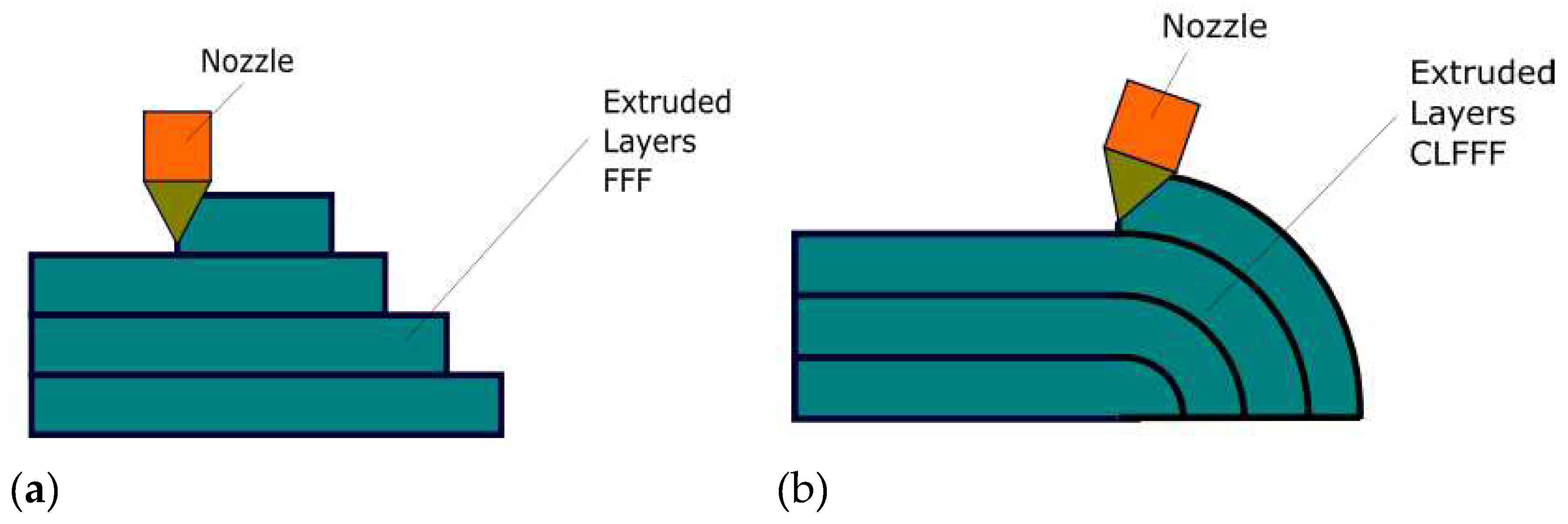
Figure 2.
General presentation of a multi-axis depositing device: (a) 3D printer with rotary table; (b) printing of thin-walled parts with the help of a robot [50]
Figure 2.
General presentation of a multi-axis depositing device: (a) 3D printer with rotary table; (b) printing of thin-walled parts with the help of a robot [50]
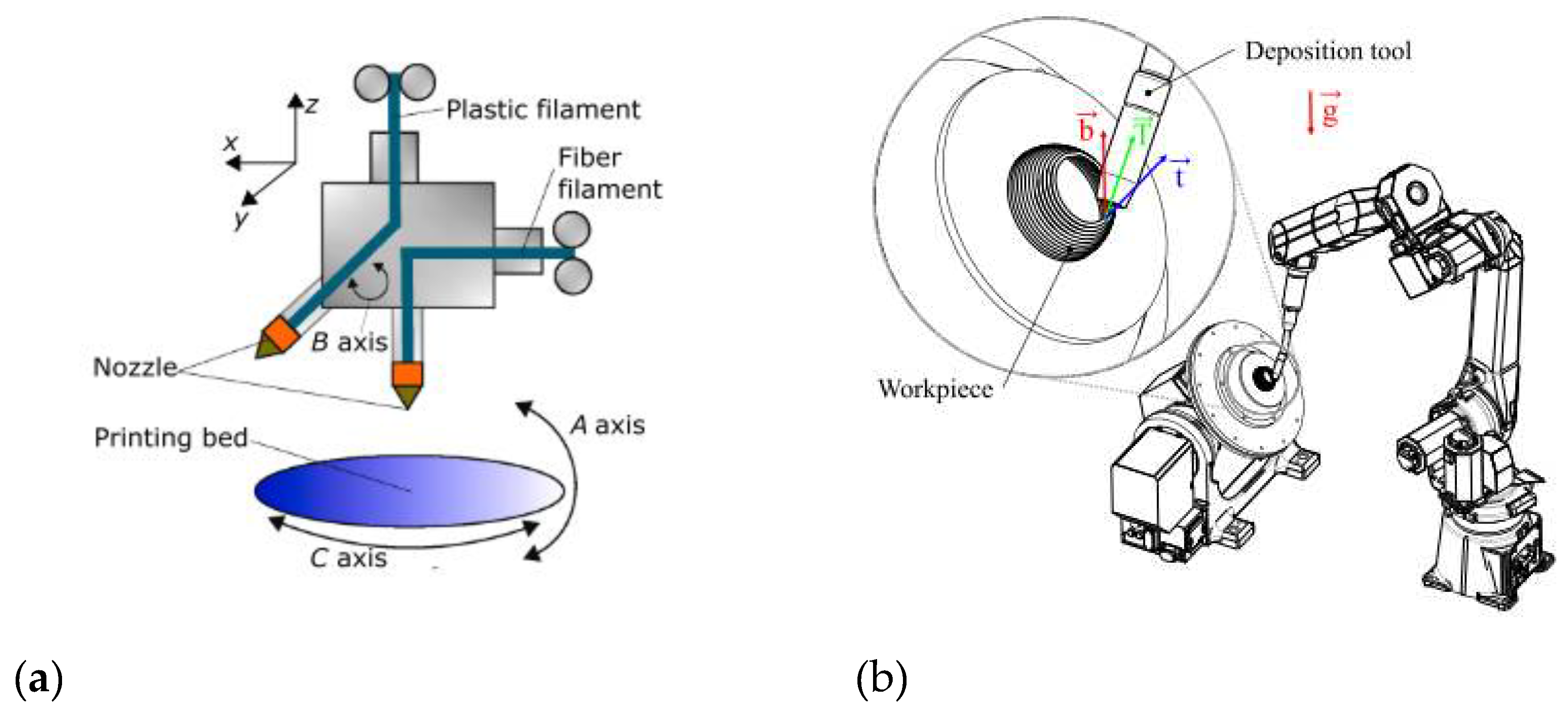
Figure 3.
Deposition/printing by orientation: (a) changing the orientation of the platform by keeping the nozzle perpendicular to the printing surface; (b) orienting the printing nozzle while the platform remains fixed.
Figure 3.
Deposition/printing by orientation: (a) changing the orientation of the platform by keeping the nozzle perpendicular to the printing surface; (b) orienting the printing nozzle while the platform remains fixed.
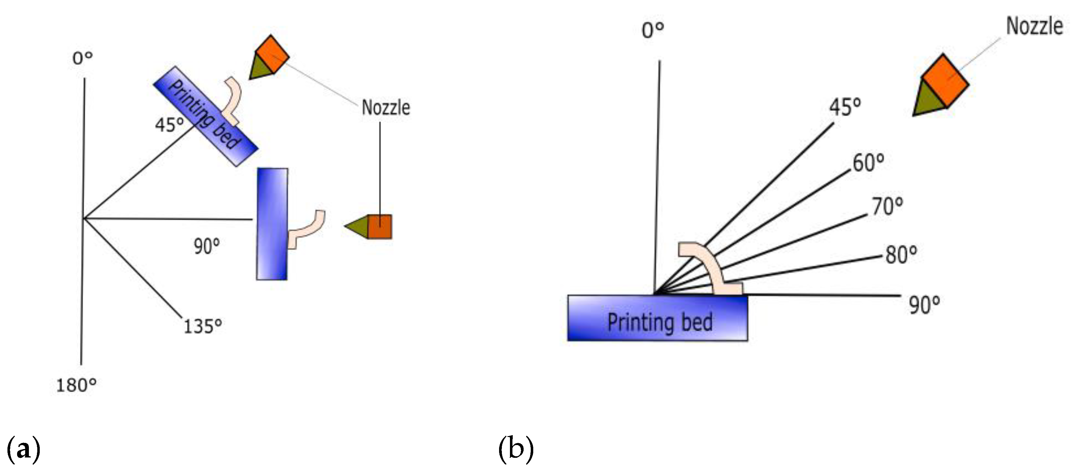
Figure 4.
Elements of constant height deposition.
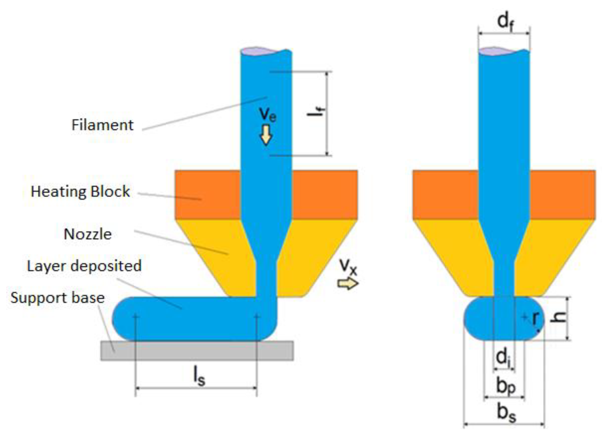
Figure 5.
Schematic representation of deposition in the case with variable-length layer
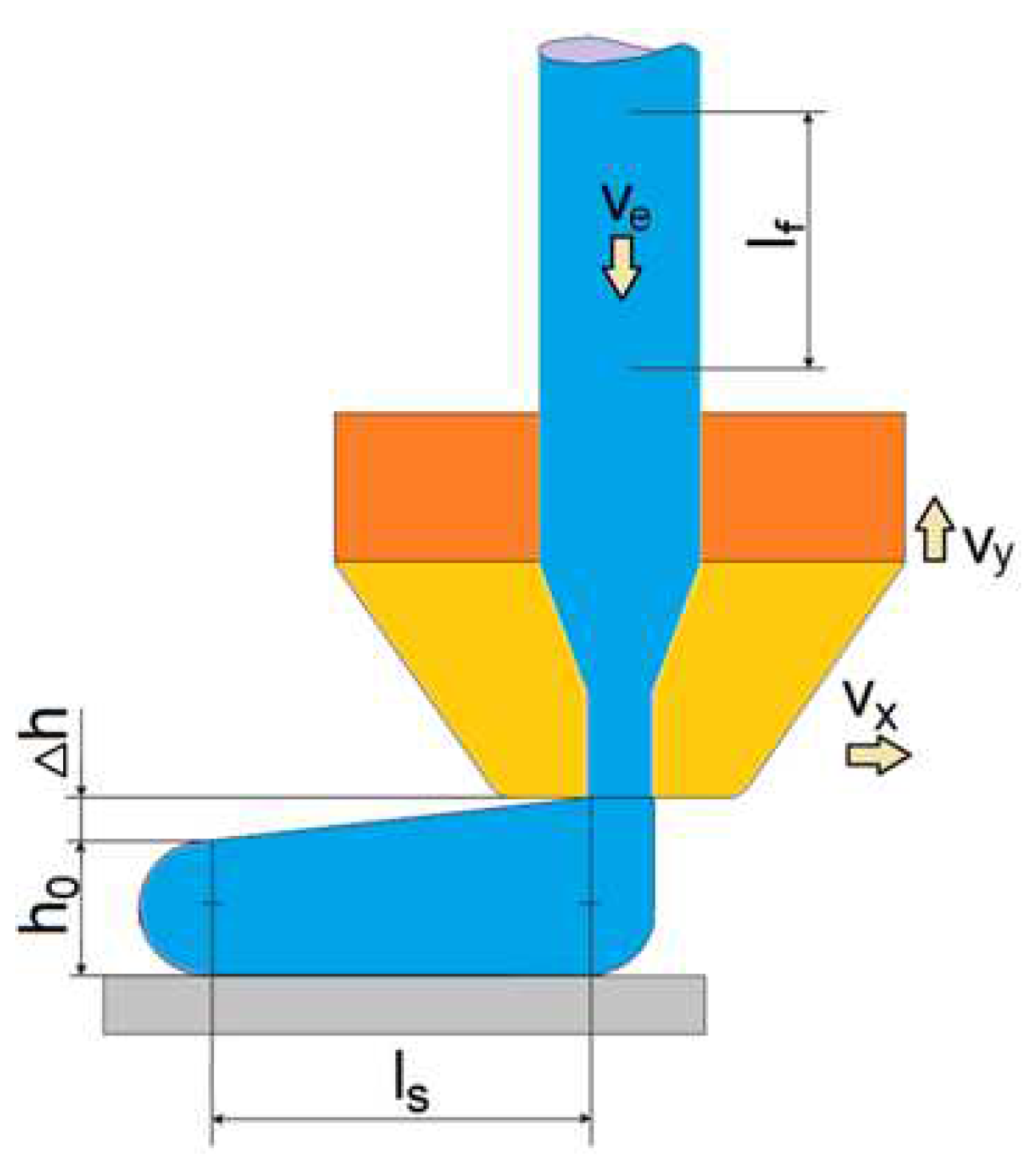
Figure 6.
Cross-section variation of the deposited layer
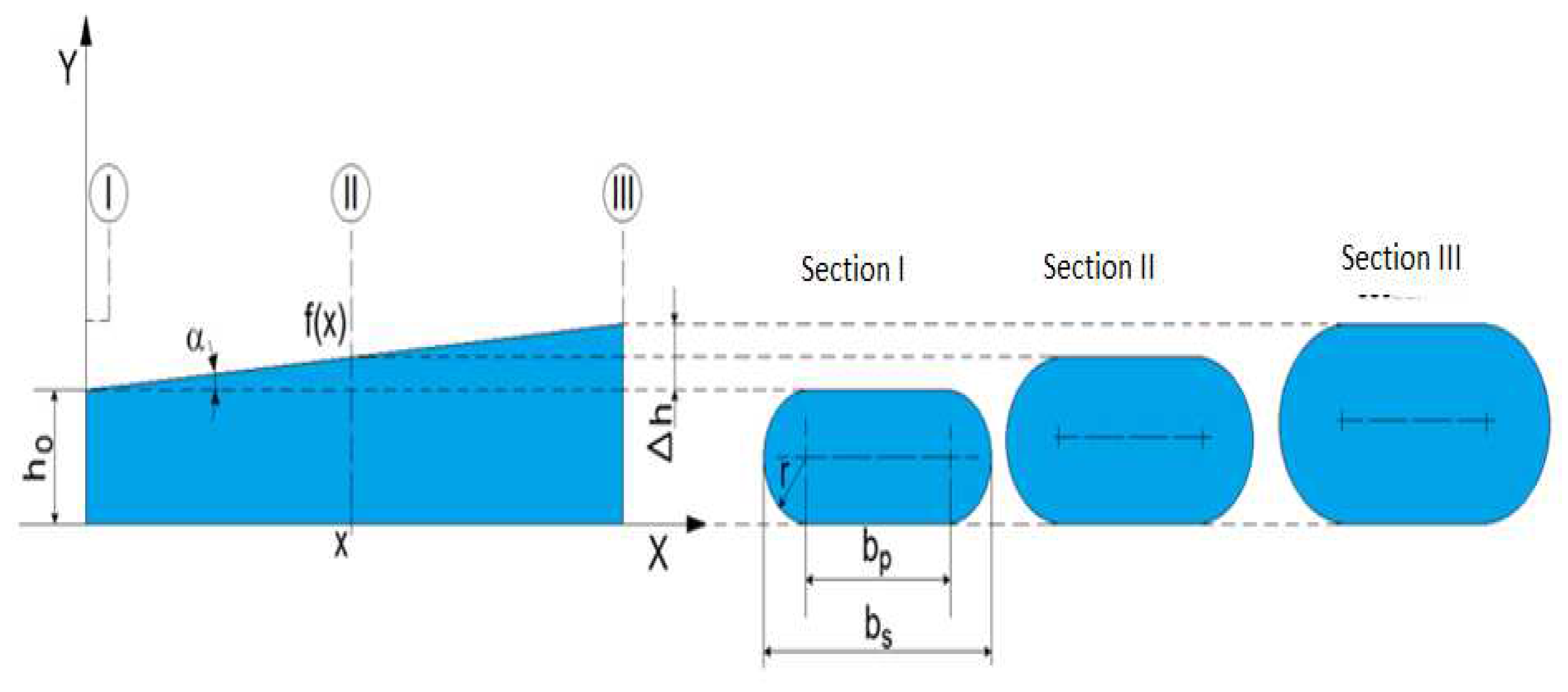
Figure 7.
The 3D model for TMA-AL-550 horizontal machining centre with CNC
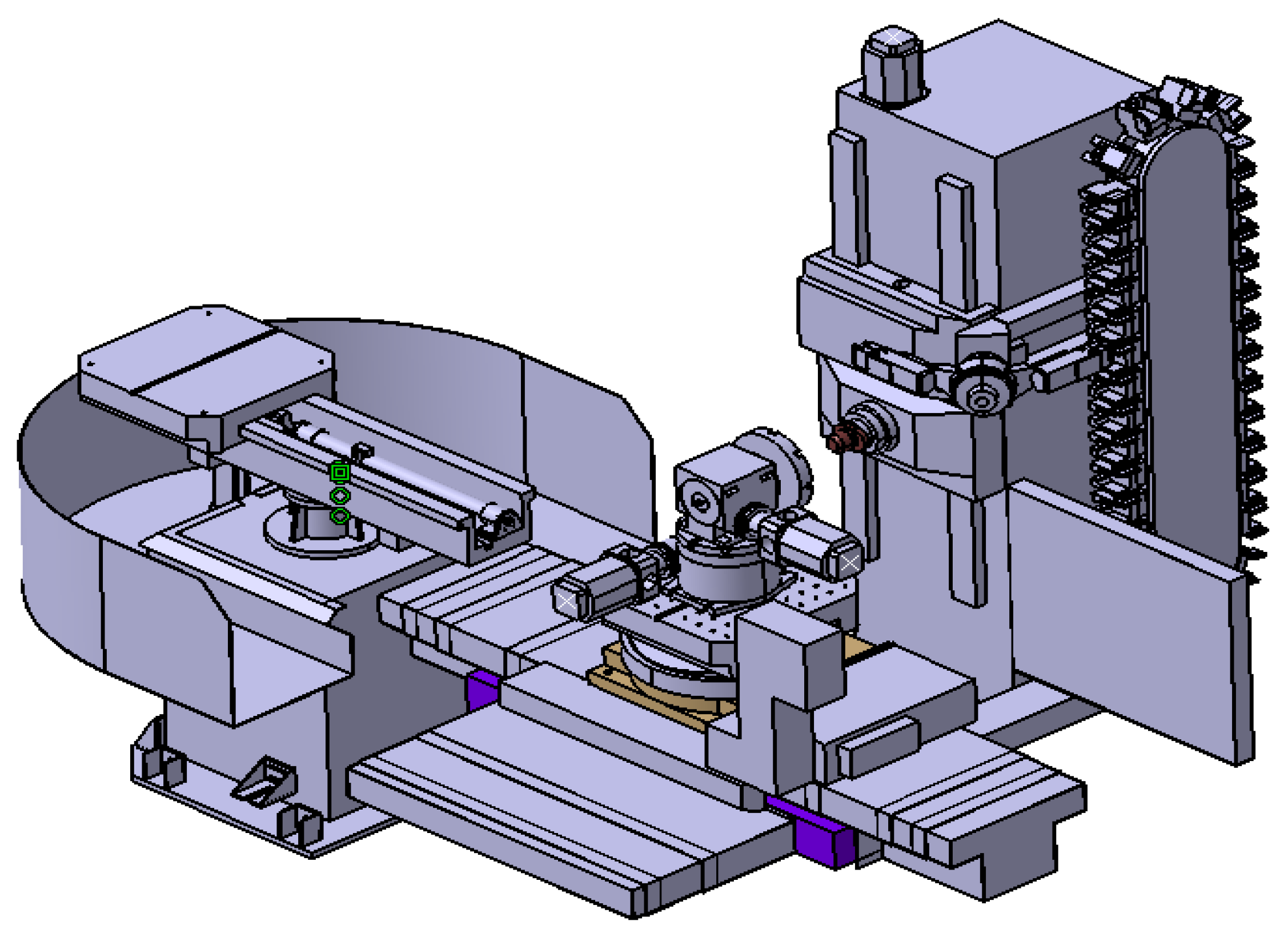
Figure 8.
Representation of a section for a curved cylindrical part.
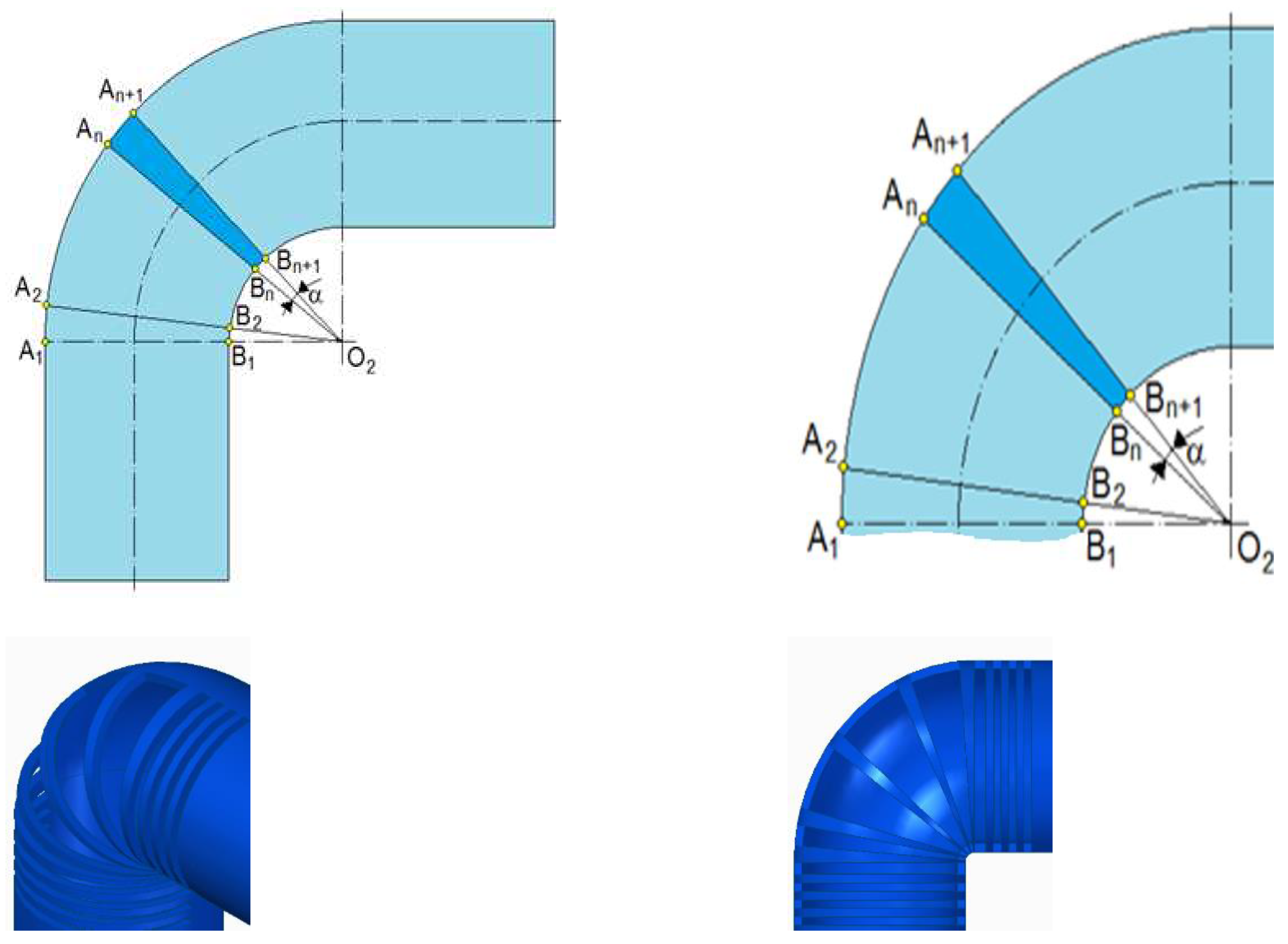
Figure 9.
The geometric elements for the circular section of variable height.
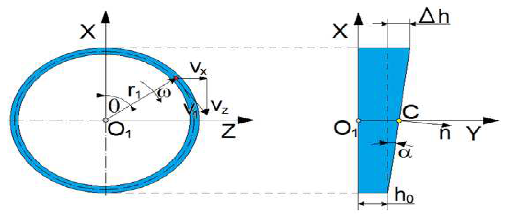
Figure 10.
The hybrid machine TMA-AL-550: (a) 3D isometric view; (b) 3d isometric view, printer head fixed on main spindle at CNC machine.
Figure 10.
The hybrid machine TMA-AL-550: (a) 3D isometric view; (b) 3d isometric view, printer head fixed on main spindle at CNC machine.
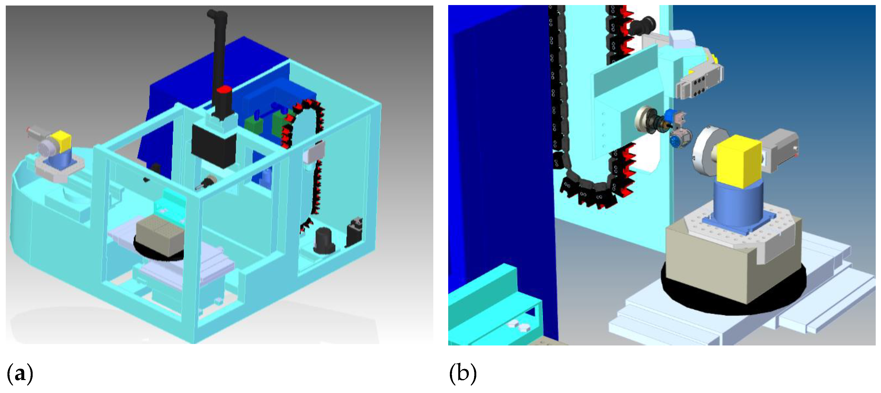
Figure 11.
Kinematic comparison of the machines: (a) TMA-AL 550 horizontal machining centre virtual concept - chipping mode; (b) TMA-AL 550 horizontal machining centre virtual concept - printing mode.
Figure 11.
Kinematic comparison of the machines: (a) TMA-AL 550 horizontal machining centre virtual concept - chipping mode; (b) TMA-AL 550 horizontal machining centre virtual concept - printing mode.

Figure 12.
Logic diagram for the CNC printing operation
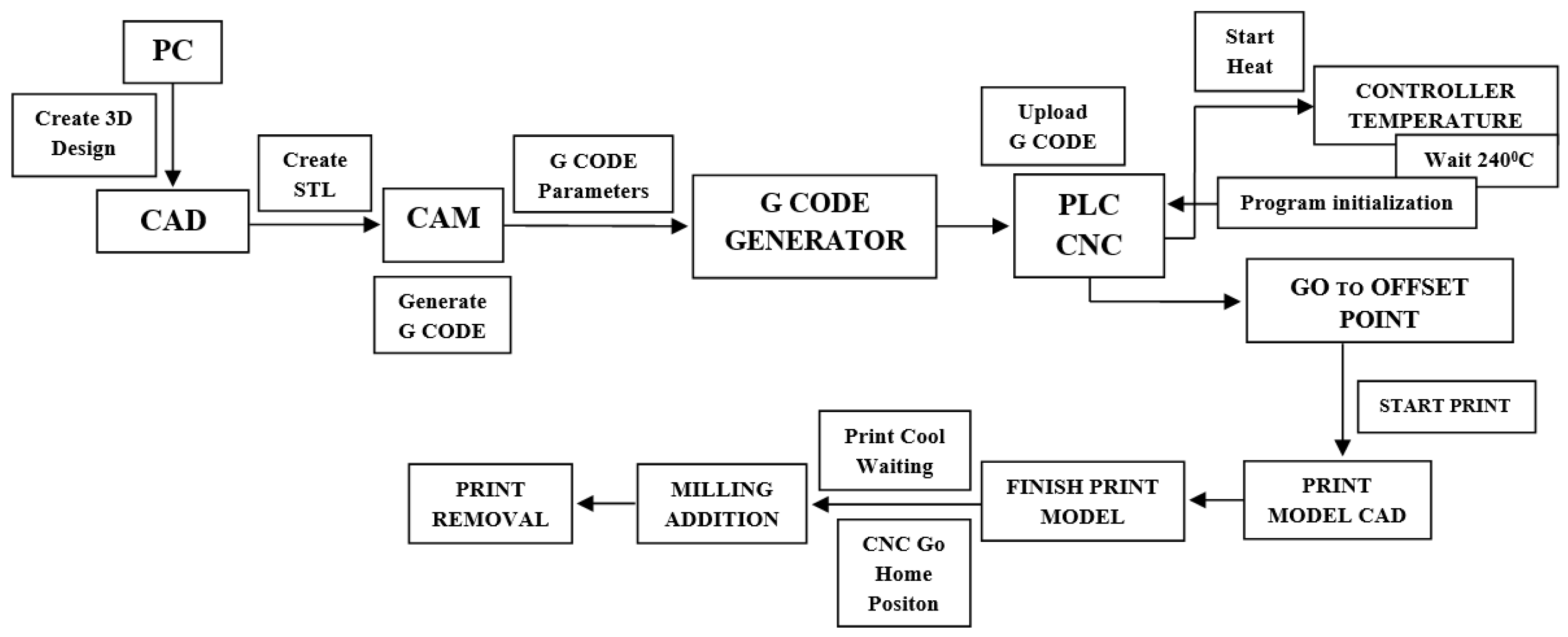
Figure 13.
Part with curved profile: (a) 3D model of the whole part; (b) curved area
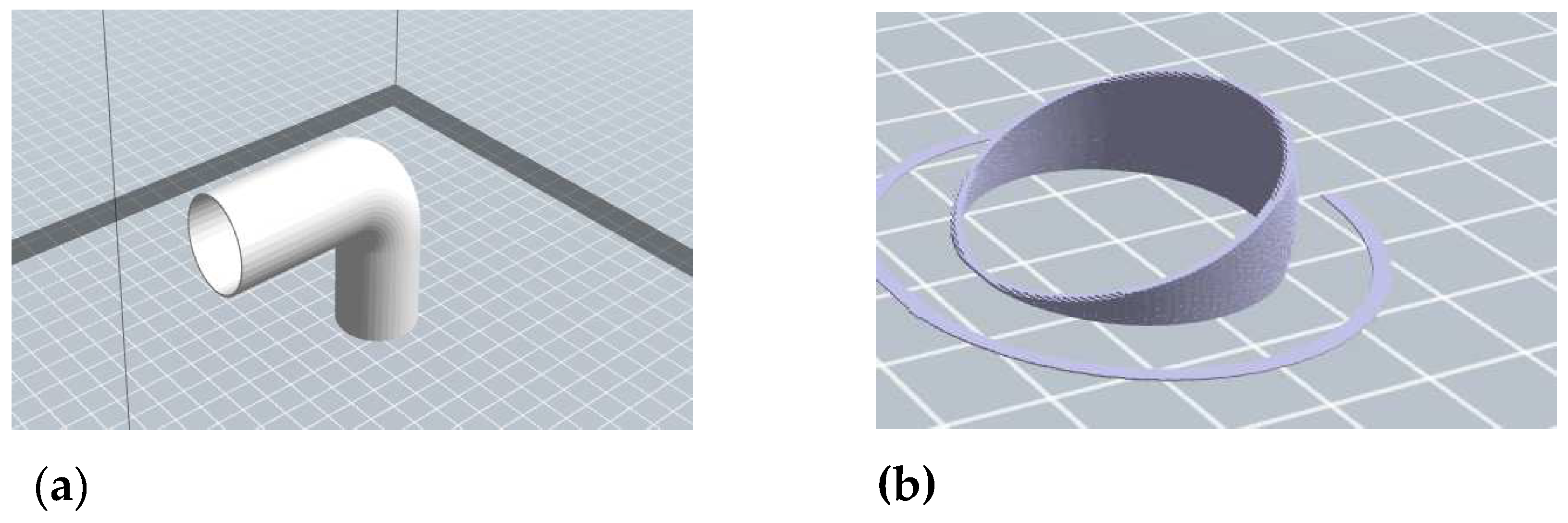
Figure 14.
Circular area wall thickness dimensions: (a) 2D model; (b) 3D model
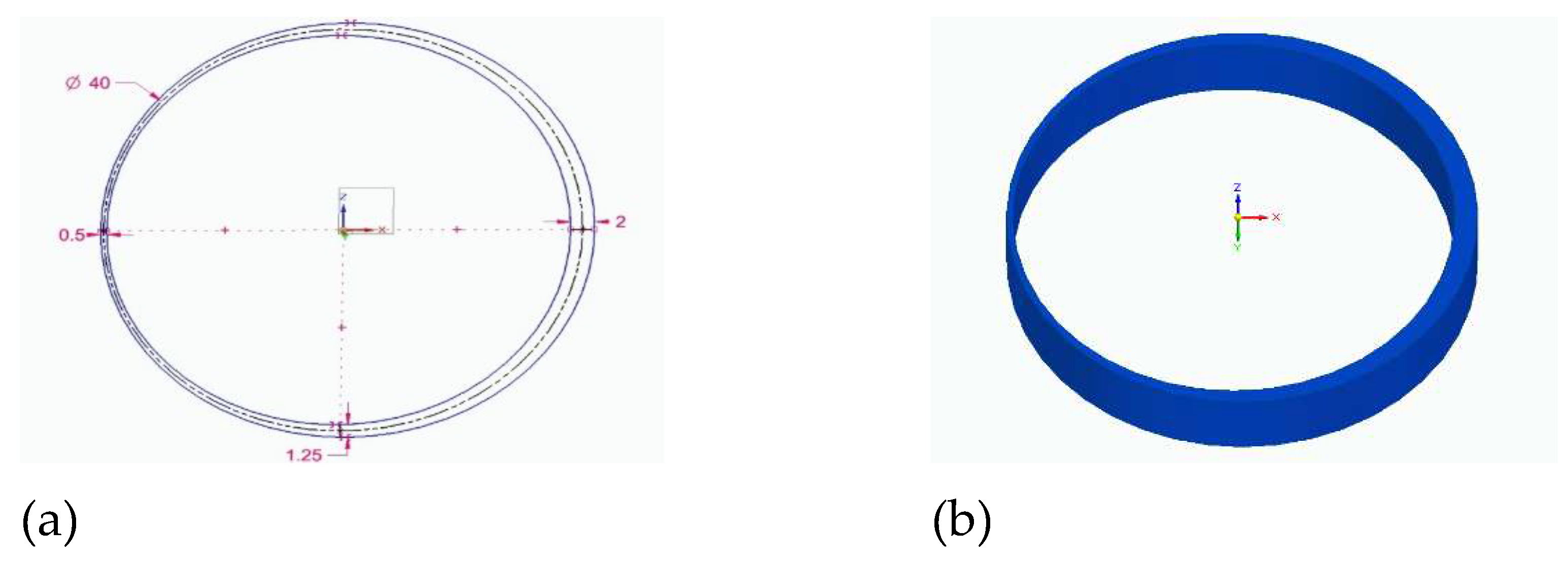
Figure 15.
Simulation of 3D printing with Flash print 5 software
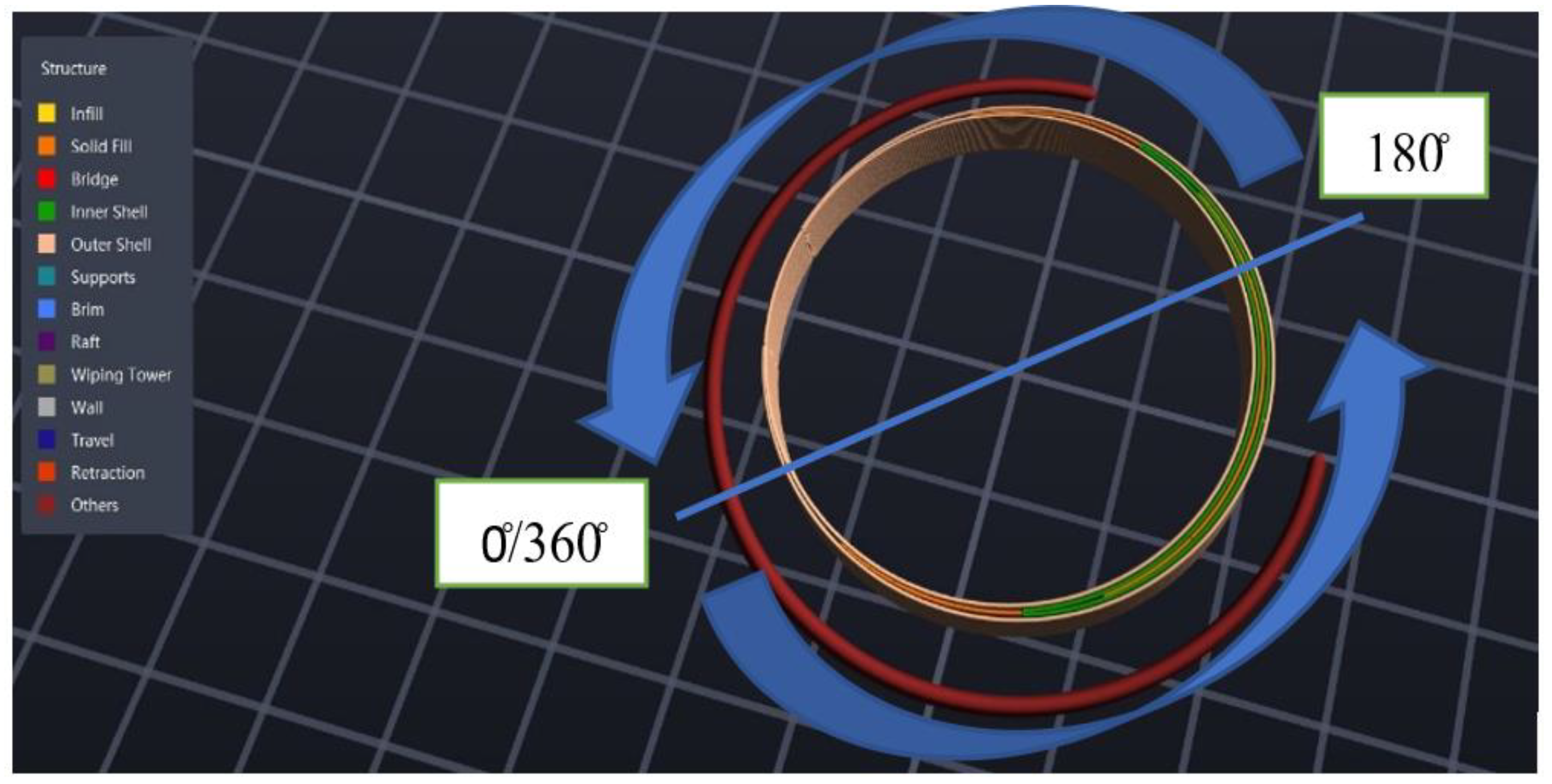
Figure 16.
Equipment’s used for printing: (a) 3D printer from Creator; (b) Simulation of printing using a support structure.
Figure 16.
Equipment’s used for printing: (a) 3D printer from Creator; (b) Simulation of printing using a support structure.
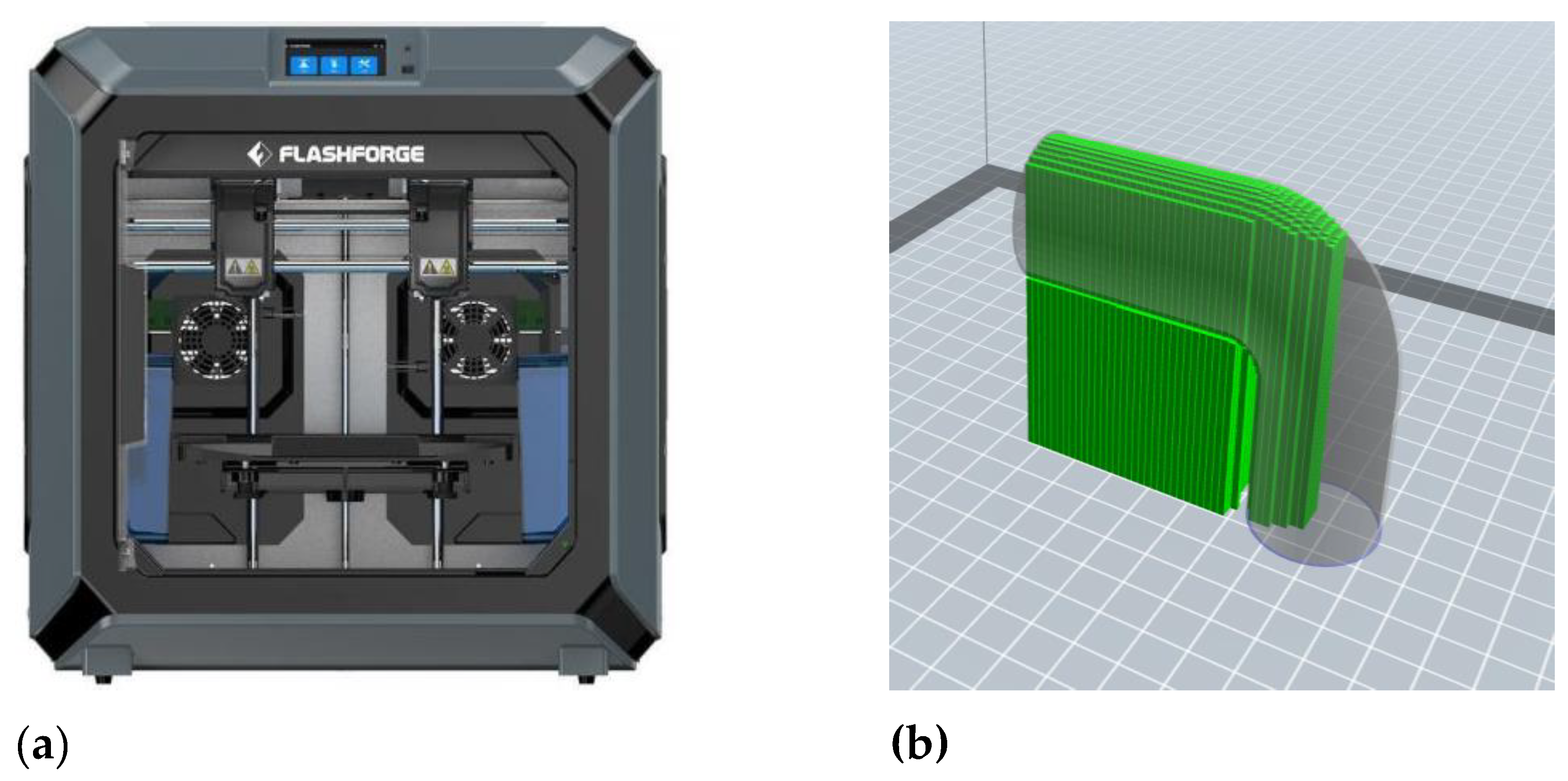
Figure 17.
The equipment used for 3d printing on machine : (a) 3D model printer head ; (b) 3D printing head attached to the TMA-AL 550 horizontal machining centre.
Figure 17.
The equipment used for 3d printing on machine : (a) 3D model printer head ; (b) 3D printing head attached to the TMA-AL 550 horizontal machining centre.
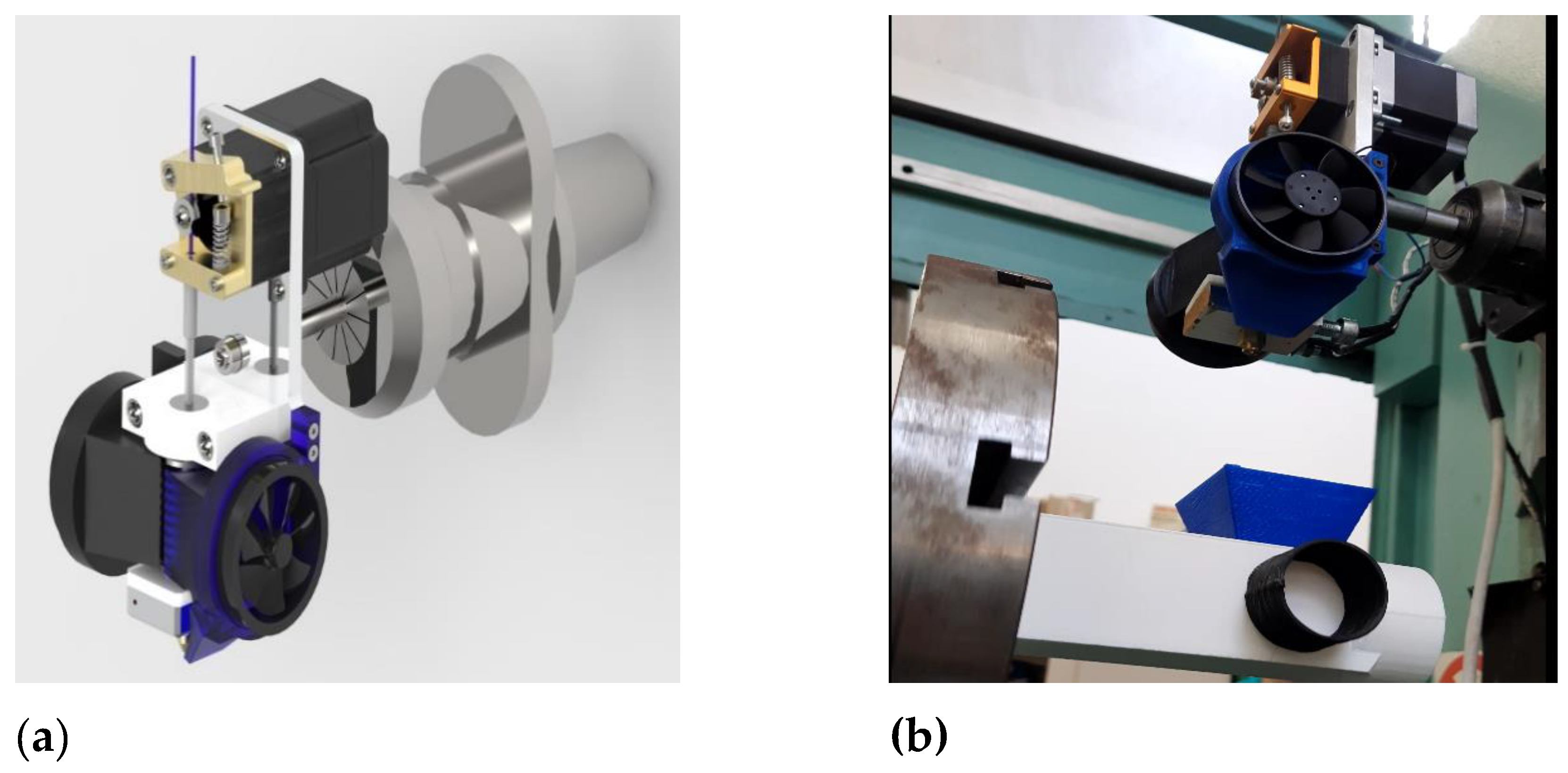
Figure 19.
Simulated program O2023.nc: (a) simulated in Cimco; (b) simulated in Fanuc 30 and TMA-AL-550 machine tooling.
Figure 19.
Simulated program O2023.nc: (a) simulated in Cimco; (b) simulated in Fanuc 30 and TMA-AL-550 machine tooling.
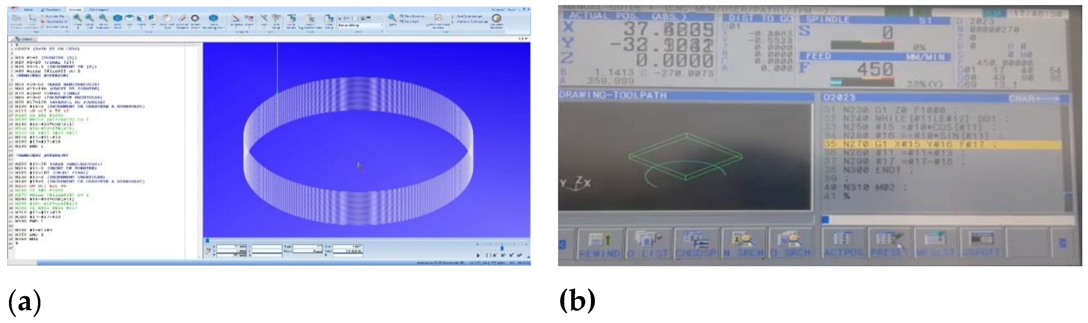
Figure 20.
Steps required to print the final elbow area completely: (a, b) printing the bending area (c, d) printing of the upper cylindrical area.
Figure 20.
Steps required to print the final elbow area completely: (a, b) printing the bending area (c, d) printing of the upper cylindrical area.
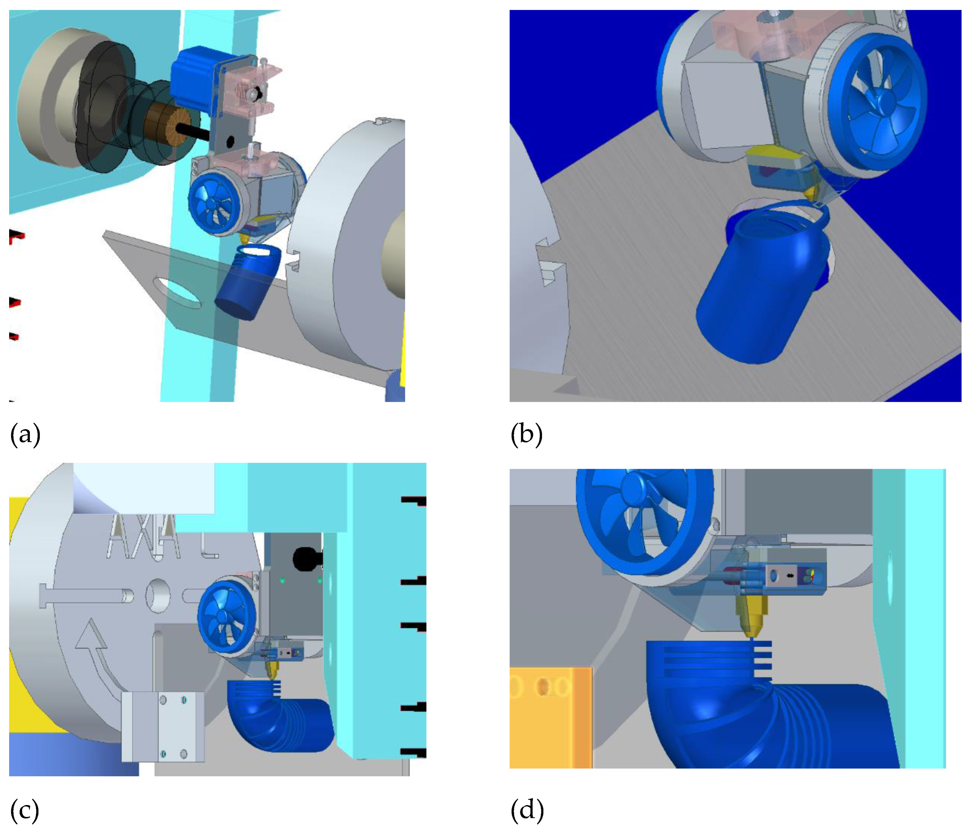

Table 1.
Determination for the printing speed as a function of melting temperature.
| Melting temperature[°C] | Type of material | Filament flow | Printing time [min] | Time [sec] | Length of filament printed [mm] | Diameter filament [mm] | Printing feed [mm/s] |
|---|---|---|---|---|---|---|---|
| 220 | PLA | 100% | 7,12 | 432 | 1000 | 1,75 | 2.31 |
| 230 | PLA | 100% | 6,34 | 394 | 1000 | 1,75 | 2.53 |
| 240 | PLA | 100% | 2,4 | 160 | 500 | 1,75 | 3.12 |
| 245 | PLA | 100% | 2,21 | 141 | 500 | 1,75 | 3.54 |
Table 2.
Parameterized Program O2024.
| % O2024 (R=100 on a circle GOTO10 (top half circle) N10 #10=100 (radius of half circle) N20 #11=180(starting angle) N30 #12=0 (end angle) N40 #13=2 (angular increment) % |
N50 #17=100 (starting increment) N60 #18=5 (incremental feed increment) N70 G0 G17 X-100 Y0 N80 G1 Z0 F1000 N90 while [#11GE#12] DO 1 N100 #15= #10*COS[#11] N110 #16= #10*SIN[#11] N120 G1 X#15 Y#16 F#17 N130 #11=#11-#13 N140 #17=#17+#18 |
N150 END 1 (lower half circle) N160 #10=100 (radius of semicircle) N170 #11=0 (starting angle) N180 #12=180 (end angle) N190 #13=2 (angular increment) N200 #17=100 (STARTING INCREMENT) N210 #18=5 (incremental feed |
INCREMENT) N220 G0 G17 X100 Y0 N230 G1 Z0 F1000 N240 WHILE [#11LE#12] DO 1 N250 #15= #10*COS[#11] N260 #16= -#10*SIN[#11] N270 G1 X#15 Y#16 F#17 N280 #11=#11+#13 N290 #17=#17-#18 N300 END 1 N310 M02 |
Table 3.
Program O2023 for printing a cylinder with variable wall thickness.
| % O2024 (R=50 ON A CIRCLE) N5 T2 M06 (PRINT HEAD CALL) N6 G0 G54 G90 G80 G18; (WORK SYSTEM SETTING, WORK PLAN, ABSOLUTE PROGRAMMING) N10 #1=0.5 (START [Z]) N20 #2=20 (END [Z]) N30 #3=0.5 (INCREMENT ON [Z]) N40 WHILE [#1LE#2] DO 2 |
(UPPER SEMICIRCLE) N50 #10=50 (RADIUS OF SEMICIRCLE) N60 #11=180 (STARTING ANGLE) N70 #12=0 (END ANGLE) N80 #13=2 (ANGULAR INCREMENT) N90 #17=100 (STARTING INCREMENT) N100 #18=5 (INCREMENTAL FEED INCREMENT) N110 G0 G18 X-50 Y0 M27 (START HEATING) N120 G1 Z#1 F1000 M23 (FILAMENT FEED START) N130 WHILE [#11GE#12] DO 1 N140 #15=#10*COS[#11] N150 |
#16=#10*SIN[#11] N160 G1 X#15 Y#16 F#17 N170 #11=#11-#13 N180 #17=#17+#18 N190 END 1 (LOWER HALF CIRCLE) N200 #10=50 (RADIUS OF SEMICIRCLE) N210 #11=0 (STARTING ANGLE) N220 #12=180 (END ANGLE) N230 #13=2 (ANGULAR INCREMENT) N240 #18=5 (FEED INCREMENT) N250 G0 G18 X50 Y0 N260 G1 Z#1 F1000 N270 WHILE |
[#11LE#12] DO 1 N280 #15=#10*COS[#11] N290 #16=-#10*SIN[#11] N300 G1 X#15 Y#16 F#17 N310 #11=#11+#13 N320 #17=#17-#18 N330 END 1 N340 #1=#1+#3 N350 END 2 N360 M02 N370 M24 (HEATING OFF) N380 M28 (FILAMENT ADVANCE STOP) N390 M30 % |
Disclaimer/Publisher’s Note: The statements, opinions and data contained in all publications are solely those of the individual author(s) and contributor(s) and not of MDPI and/or the editor(s). MDPI and/or the editor(s) disclaim responsibility for any injury to people or property resulting from any ideas, methods, instructions or products referred to in the content. |
© 2023 by the authors. Licensee MDPI, Basel, Switzerland. This article is an open access article distributed under the terms and conditions of the Creative Commons Attribution (CC BY) license (https://creativecommons.org/licenses/by/4.0/).
Copyright: This open access article is published under a Creative Commons CC BY 4.0 license, which permit the free download, distribution, and reuse, provided that the author and preprint are cited in any reuse.


