Submitted:
05 September 2023
Posted:
07 September 2023
You are already at the latest version
Abstract
This paper aims to determine the effect of local corrosion at three different corrosion areas, the 1. entire area, 2. constant moment area, and 3. constant shear area, on the flexural performance of RC beams. To analyze this, an experimental study was carried out to prepare two series of RC beams (200×300×2800mm) created with three different degree of corrosion inducing local rebar corrosion. Furthermore, two-series of experimental tests were conducted under different loading types by monotonic and cyclic loading. It was observed that strength capacity reduction grows in the order of the corroded RC specimens induced: the 1. entire area > 2. constant moment area > 3. constant shear area, as the average corrosion rate increases. Our test results further show that the yield and ultimate strength was kept nearly equivalent to the uncorroded RC specimen by the average corrosion rate of 10% and 15%, respectively. Over these corrosion rates, the yield strength and ultimate strength dropped significantly. Compared to test results under a monotonic loading condition, the structural capacity under a cyclic loading condition decreased with a more pronounced tendency for each corrosion case as the corrosion rate increased. A longitudinal crack was developed throughout and adjacent to the corrosion areas, as the corrosion rate increased. Thus, we can infer that strength reduction may be strongly influenced by this longitudinal crack.
Keywords:
RC beam specimen
; local rebar corrosion
; degree of corrosion
; corrosion rate
; corrosion area
; monotonic loading
; cyclic loading
; structural performance
1. Introduction
The deterioration of concrete structures caused by reinforcement corrosion is being reported in an increasing number of structures [1,2]. Subsequently, the importance of making a precise estimation of durability and the remaining life of rebar corroded RC structures and drafting a reasonable maintenance and conservation plan has become an essential task [3,4]. To solve this problem, it is necessary to clearly understand the effect of rebar corrosion on RC structures [5-7], and provide an accurate evaluation of structural performance degradation of RC structures [8-11].
Typically, corrosion is caused by incorporation into the concrete mixture [12], the attack of chloride ions penetrating by diffusion from the outside [13-19], carbonation of the concrete cover [17-18,20], or a combination of these issues [21-29]. As corrosion progresses, the expansive displacement at the interface generated by accumulating rust products causes tensile stress in the hoop direction within the concrete cover [30], leading to radial splitting cracks in the cover concrete [11,16,22,28,31-38].
The cracking and spalling of the concrete cover have a significant impact on the bond strength between the rebar and the surrounding concrete cover [5, 39-43]. A few analytical models have been proposed for estimating the residual bond strength of corroded rebar in concrete structures, based on the prediction of crack growth in the concrete cover [5, 40, 41, 44-46].
As corrosion further progresses, the reduction of the rebar cross-sectional area, yield strength of the corroded rebar, bond strength, and loss of the concrete cross-sectional area in the tensile area collectively lead to a gradual decrease in the load carrying capacity of the corroded reinforced concrete structures [4, 47-52]. Experimental studies have previously been carried out on the effect of uniform reinforcement corrosion on the residual load carrying capacity of corroded concrete beams [3, 4, 48, 52-57]. The mechanical behavior of corroded concrete beams is characterized by a reduction in the bending capacity and a shift in the failure mode [10, 58-61]. Consequently, the change of failure mode, such as from rebar tensile yielding failure at the earlier corrosion stage or rebar anchorage failure due to insufficient bond strength, must be considered in predicting the residual flexural capacity of the corroded concrete beams [48, 52, 62, 63].
However, in real structures, not every part of the structure deteriorates even though it is of the same member and under the same condition [15, 48, 64-67]. Similarly, sections of the members and reinforcing bars corroded unevenly [49, 68]. The mechanical performance of reinforced concrete structural members is influenced by the complex interplay between deteriorated and sound parts of the structural member.
This paper aims to determine the effect of local corrosion at three different corrosion areas on the flexural performance of RC beams. To analyze this, an experimental study was carried out to prepare two series of RC beams(200×300×2800mm) created with three different degree of corrosion inducing local rebar corrosion. And two-series of experimental tests were conducted under different loading types by monotonic and cyclic loading.
2. Experimental Program
2.1. Experimental Parameters
This study examines the effects of rebar corrosion on RC beam specimens in terms of degradation of mechanical performance. The local corrosion at different areas of rebar and the degree of rebar corrosion are the parameters used to analyze these effects. Table 1 presents the test parameters used in this study with variables for the rebar corrosion patterns, corrosion levels and loading conditions.
Three patterns of local rebar corrosion were adopted in this study for the experimental program. The first is corrosion of the entire area, which has corroded rebar on the entire span length of the beam specimen. Next is partial corrosion in the constant moment area which has corroded rebar, located in the flexural area. The last is partial corrosion in the constant shear area, which contains corroded rebar on the shear area on both sides of the beam specimen.
The average levels of corrosion for the 3 tested patterns were 5%, 10%, and 30% of the weight loss ratio. To estimate the effect of local corrosion at the three different corrosion areas on the flexural performance of RC beams, two-series of experimental tests were conducted under different loading types by monotonic and cyclic loading.
2.2. Materials and Specimen Preparation
Table 2 presents the mix design and material properties for the concrete mixtures used in this study. Ordinary portland cement was used with a water-cement ratio of 56.2%. After 28 days, the concrete exhibits a compressive strength of 21.1 MPa and an elastic modulus of 21.06 GPa.
The reinforcements used were SD 295A with D13 in the longitudinal at the bottom and at the top, and D10 as stirrups of the beam. The properties of this reinforcement are presented in Table 3. The yield strength, the maximum tensile strength, and the elastic modulus of D13 rebar are 412.8 MPa, 589.4 MPa, and 180.9 GPa, respectively. D10 rebar has a yield strength, maximum tensile strength, and elastic modulus of 371.1 MPa, 545.3 MPa, and 216.3 GPa, respectively.
A total of 20 test specimens were fabricated, consisting of one specimen for each experimental parameter shown in Table 1, and one reference specimen for each loading condition. Each beam specimen had a 200×300 mm square cross-section and was 2,800 mm in length. Figure 1 shows the test specimen and reinforcement details. The tension side of the beam specimens were reinforced with three D13 rebars, and three D10 rebars were embedded on the compression side.
2.3. Electric Corrosion of Rebar Method
Figure 2 shows a schematic drawing of the test set-up used in this study. An acrylic pool containing sodium chloride (3% NaCl) aqueous solution was fabricated at the surface of the beam specimens by filling it to half of the specimen and inserting copper plates into the pool.
The location of the pool was adjusted based on the effective area of the concrete surface. An approximately l mA/cm2 electric current was applied with a power supply between the rebars (an anode) and the copper plates (a cathode).
Figure 3 shows the anode connection methods for local corrosion at the three different corrosion areas ((a) entire area corrosion, (b) constant moment area corrosion: mid area, and (c) constant shear area corrosion: end area) on the flexural performance of RC beams.
In the case of local corrosion of the entire area, the corrosion area was targeted for the tension side of the main reinforcement and the lower half of the shear reinforcements. To allow current to flow only through the desired corrosion area, wires were connected to the main reinforcement and shear reinforcement on the tension side. In the case of constant moment area, the tension side of the main reinforcement and the lower half of the shear reinforcements of the flexural reign are targeted at the 400 mm reign of mid-span. In the case of the constant shear area, both sides of the shear area were targeted (not the entire shear area, but a 300 mm segment located 20 mm away from the support points).
The corrosion weight loss (%) of the rebar was measured after the tests were completed. The weights before and after corrosion were obtained after eliminating the corrosion products from the corroded sections of the rebar, which were extracted from the concrete using a 10% citric acid and ammonium solution.
2.4. Loading Test of the Specimen Method
- (1)
- Monotonic Loading Test
A static loading experiment was conducted on a corroded reinforced concrete beam specimen. The loading method used in this study was a simply supported configuration, with two-point loads applied at the center of the beam. The shear span-to-depth ratio was 3.33. During the test, both the applied load and the deflection at the center of the span were measured, and the progression of cracks was observed. An overview of the monotonic loading experiment is illustrated in Figure 4.
- (2)
- Cyclic Loading Test
In the cyclic loading experiment, the load was set according to the deformation angle of the test specimen corresponding to different levels: 1/1000 (1.2 mm deflection at the center of the beam), 2/1000 (2.4 mm), 4/1000 (4.8 mm), 8/1000 (9.6 mm), 16/1000 (19.2 mm), 32/1000 (38.4 mm), and 64/1000 (76.8 mm). Each deformation level was repeated three times with load-unload cycles from 0 to the respective deformation angle, and then back to zero.
During the loading phase, displacement was controlled, and loading was applied at the loading point at a speed of 0.025 mm/sec. The unloading phase was carried out instantaneously. Figure 5 shows photos of the flexural loading test on the specimen.
3. Test Results and Discussions
In this study, test results are presented in terms of the rebar corrosion rate in concrete beams, the yield load, and maximum load under different loading conditions and deflection measurements at each loading level. Table 4 summarizes corrosion weight loss and mechanical test results.
3.1. Test Results under Monotonic Loading
The evaluation test results of the structural capacity of the RC beam specimens under monotonic loading, according to the corrosion rate of the rebar, are shown in Figure 6. Overall, as the corrosion rate of the rebar increased, the structural capacity of the beam specimens tended to decrease. Deflection values at the yield and maximum load do not provide any meaningful significance.
Particularly, in the case of rebar corrosion of the entire area, the structural capacity was significantly impaired due to the corrosion of the rebar. For specimens A-1-1 and A-2-1, it was observed that both the yield load and maximum load were substantially reduced to a range between 14.5-17.7% and 12.3-16.1%, respectively. Furthermore, specimen A-3-1 showed a dramatic reduction of 40.1% in yield load and 35.2% in maximum load.
In the case of localized corrosion in the constant moment area, the reduction in yield load was reduced to be 12.9-24.3%, which is a similar extent to the specimens with the entire area corrosion. And the reduction in structural capacity at the maximum load, at the same corrosion rate, was less pronounced in the range of 3.0-17.6%.
For localized corrosion in the constant shear area, the reduction in structural capacity was insignificant compared to the entire area corrosion and the constant moment area corrosion cases. The yield load and maximum load were reduced by 0.5-16.0% and 5.6-9.9%, respectively. However, specimen S-1-1 resulted in an increase of 5.9% in the yield load and 0.3% in the maximum.
Under monotonic load, the yield load and maximum load of RC beam specimens considering the corrosion of the rebar are presented in Figure 7. Generally, an increasing corrosion rate resulted in a decrease in structural capacity. However, it was found that localized corrosion in the constant shear area did not significantly affect the structural capacity up to an average corrosion rate of 15%.
Figure 8 presents the localized average weight loss rates of the tensile reinforcement and stirrups in the monotonically loaded beam specimens after corrosion. Overall, it was observed that an increase in the average corrosion rate of the reinforcement resulted in a significant decrease in the load-carrying capacity of the beam specimens. In the case of rebar corrosion of the entire area, specimen A-2-1 resulted in a slightly higher average corrosion rate from the longitudinal rebar B, compared to specimen A-1-1. An additional average weight loss of 3.8% leads to a 4.3% reduction in maximum load capacity. In the case of localized corrosion in the constant moment area, the average corrosion rates from specimens B-1-1 and B-2-1 are nearly identical, and an average weight loss difference of 1.2% causes a 3.0% reduction in maximum load capacity. For localized corrosion in the constant shear area, the average corrosion rate increases in the order of S-3-1>S-2-1>S-1-1. The stirrups in specimen S-3-1 were significantly more corroded and had the lowest maximum load capacity.
Figure 9 illustrates the crack patterns in the concrete cover and the occurrence of cracks with corroded rebar due to imposed monotonic loads in the beam specimens. First, it was observed from the reference specimen (REF-1) that flexural cracks mainly occurred at an average interval of approximately 100 mm from the center of the specimen. The middle strip denotes the bottom face of the specimen while the upper strip and lower strip denote the front face and the rear face of the specimen, respectively. During monotonic loading, the failure mode of the beam specimens with corroded rebar was similar to the reference beam specimens. An increase in the corrosion rate of the rebar led to wider crack widths and influenced crack occurrence under further loading. However, even in the case of specimen A-3-1 with the highest degree of rebar corrosion, concrete spalling did not occur. It is obvious from the bottom face that the longitudinal cracks were noticed throughout and adjacent to the corrosion areas (see specimens A-1-1, A-2-1, and A-3-1 for rebar corrosion of the entire area; B-2-1 and B-3-1 for localized corrosion in the constant shear area, and S-1-1 and S-3-1 for localized corrosion in the constant shear area). A-3-1 clearly shows that strength reductions were strongly influenced by two main longitudinal cracks at the bottom side and a scattered longitudinal crack at the front side. No diagonal shear failure occurred in all the specimens.
3.2. Test Results under Cyclic Load
The structural capacity test results of RC beam specimens under cyclic loading, according to the corrosion rate of the rebar, are shown in Figure 10. Similar to the test results under monolithic load, as the corrosion rate of the rebar increased, the structural capacity of the beam specimens tended to decrease.
In the case of the entire corrosion area, in specimens A-1-2 and A-2-2, Table 4 shows that average weight loss was nearly identical: about 10.6 % while the yield load and maximum load were reduced to 14.7% and 5.7%, respectively. In specimen A-3-2, it was observed that the yield load and ultimate load reduction were significant at 69.6% and 60.9%, respectively, with an average corrosion rate of 33.1%.
For localized corrosion in the constant moment area, as the average weight loss increased from 10.5% (specimen B-1-2), 14.2% (specimen B-2-2), and 21.5% (specimen B-3-2), the reduction in the yield load and ultimate load was 7.6%, 17.9%, 34.8% and 0.0%, 8.1%, 26.0%, respectively, as tabulated in Table 4. Over the average of 20% weight loss, specimen B-3-2 exhibited a considerable deterioration in structural performance.
For localized corrosion in the constant shear area, the reduction in structural capacity was not as significant than the other cases.
Under cyclic load, the yield load and maximum load of RC beam specimens considering the corrosion of the rebar are presented in Figure 11. Compared to the test results under a monotonic loading condition shown in Figure 8, the structural capacity in terms of yield strength and ultimate strength decreased with a more pronounced tendency for each corrosion case as the corrosion rate increased. Excluding the deviated data in Figure 11 (9.35 tf at an average of 14.75% corrosion weight loss, denoted as the solid rectangular symbol), the reduction in load-carrying capacity due to average corrosion rates of up to 10% shows a similar trend. However, beyond this corrosion rate, a significant deterioration in load-carrying capacity is observed especially in the entire area and localized moment area.
Figure 12 presents the localized average weight loss rates of the tensile reinforcement and stirrups in the cyclic loading conditions after corrosion. Similar to the monotonic load cases, it was observed that an increase in the average corrosion rate of the reinforcement resulted in a significant decrease in the load-carrying capacity of the beam specimens.
In the case of rebar corrosion of the entire area, similar corrosion loss results were obtained from specimens A-1-2 and A-2-2. At approximately a 10.6% corrosion rate from those specimens, the average ultimate strength was decreased to 5.7%. It is clearly shown from the test values of specimen A-3-2 in Figure 12 that the average corrosion rate fluctuates by location. In addition, about 33% of the average corrosion rate caused a 69.6% drop in yield strength and 60.9% drop in ultimate strength. In the case of localized corrosion in the constant moment area, a gradual increase of average corrosion rate in the order of B-3-2>B-2-2>B-1-2 leads to corresponding strength reductions. For localized corrosion in the constant shear area, the average corrosion rate increased in the order of S-2-2>S-3-2>>S-1-2. Although specimen S-1-2 was corroded as 7.9%, the ultimate strength was equivalent to the reference specimen. However, specimens S-2-2 and S-3-2 corroded as 14.8% and 12.0%, causing an ultimate strength reduction of 5.1% and 4.9%, respectively.
Figure 13 illustrate the crack patterns in the concrete cover and the occurrence of cracks with corroded rebar due to imposed cyclic loads in the beam specimens. Except for specimen A-3-2, approximately 100 mm crack intervals were observed from the center of all specimens.
Similar to the monotonic loading case (see Figure 9), the bottom face clearly shows longitudinal cracks throughout and adjacent to the corrosion areas (see specimens A-1-2, A-2-2, and A-3-2 for rebar corrosion of the entire area; B-3-2 for localized corrosion in the constant shear area, S-2-2 and S-3-2 for localized corrosion in the constant shear area). Furthermore, specimens A-3-2 and B-3-2 clearly show that strength reductions were strongly influenced by a couple of main longitudinal cracks at the bottom side. Specimen A-3-2 particularly exhibits two main flexural cracks toward the two load points which might be attributed to very high local corrosion occurring along with the longitudinal rebars B and C aligning with the load points. No diagonal shear failure occurred in all the specimens.
4. Conclusion
This paper aimed to determine the effect of different corrosion rates on the flexural performance of RC beams. To analyze this, an experimental study was carried out by preparing two series of RC beams and inducing local rebar corrosion at three different corrosion areas: 1. the entire area, 2. the constant moment area, and 3. the constant shear area). Two-series of experimental tests were conducted under different loading types by monotonic and cyclic loading. The results acquired from this study describe below.
- (1)
- The yield load and ultimate load of RC beams decreased with the increase of rebar corrosion rate, regardless of the imposed corrosion areas and the loading types. This was consistent with the observed surface longitudinal cracks developed throughout and adjacent to the corrosion areas as the rebar corrosion rate increased.
- (2)
- It was observed that the reduction in ultimate load and yield load becomes larger in the order of the corroded RC specimens induced at 1. the entire area > 2. the constant moment area > 3. the constant shear area, compared to the value of the referenced uncorroded RC specimen, as the average corrosion rate increases.
- (3)
- Test results further reveal that the yield and ultimate strength was kept almost equivalent to the uncorroded RC specimen by the average corrosion rate of 10% and 15%, respectively. Over this corrosion rate, the yield strength and ultimate strength were evidently dropped.
- (4)
- Compared to test results under monotonic loading condition, the structural capacity under a cyclic loading condition decreased with a more pronounced tendency for each corrosion case as the corrosion rate increased.
- (5)
- The crack spacing in the flexural zone was nearly identical irrespective of the different corroded RC beams and loading types. A longitudinal crack was developed throughout and adjacent to the corrosion areas, as the corrosion rate increased. It is thus inferred that strength reduction may be strongly influenced by the incurred longitudinal crack.
Author Contributions
H.K. conceptualization, methodology, writing-original draft preparation, S.Y. analysis, writing-final draft preparation, T.N. supervision, S.Y. validation, writing-introduction and review.
Conflicts of Interest: The authors declare no conflict of interest.
Acknowledgements
This study was conducted under research Project(22POQW-B152690-04) funded by the Ministry of Land, Infrastructure and Transport(MOLIT) and the Korea Agency for Infrastructure Technology Advancement(KAIA). The authors would like to thank the members of the research team, MOLIT and KAIA for their guidance and supports throughout the project.
References
- ASCE. 2005 report card for America's infrastructure. 2005.
- INFRASTRUCTURE, O.A.S. A comprehensive assessment of America’s infrastructure. 2021.
- Torres-Acosta, A.A.; Navarro-Gutierrez, S.; Terán-Guillén, J. Residual flexure capacity of corroded reinforced concrete beams. Eng Struct 2007, 29, 1145–1152. [Google Scholar] [CrossRef]
- Chen, H.-P. Residual flexural capacity and performance assessment of corroded reinforced concrete beams. J Struct Eng 2018, 144, 04018213. [Google Scholar] [CrossRef]
- Coccia, S.; Imperatore, S.; Rinaldi, Z. Influence of corrosion on the bond strength of steel rebars in concrete. Mater Struct 2016, 49, 537–551. [Google Scholar] [CrossRef]
- Torres-Acosta, A.A.; Fabela-Gallegos, M.J.; Munoz-Noval, A.; Vazquez-Vega, D.; Hernandez-Jimenez, J.R.; Martinez-Madrid, M. Influence of corrosion on the structural stiffness of reinforced concrete beams. Corrosion-Us 2004, 60, 862–872. [Google Scholar] [CrossRef]
- Zhu, W.J.; Francois, R.; Coronelli, D.; Cleland, D. Effect of corrosion of reinforcement on the mechanical behaviour of highly corroded RC beams. Eng Struct 2013, 56, 544–554. [Google Scholar] [CrossRef]
- Cairns, J.; Du, Y.; Law, D. Structural performance of corrosion-damaged concrete beams. Mag Concrete Res 2008, 60, 359–370. [Google Scholar] [CrossRef]
- Huang, L.; Ye, H.L.; Jin, X.Y.; Jin, N.G.; Xu, Z.N. Corrosion-induced shear performance degradation of reinforced concrete beams. Constr Build Mater 2020, 248, 118668. [Google Scholar] [CrossRef]
- Naderpour, H.; Ghasemi-Meydansar, F.; Haji, M. Experimental study on the behavior of RC beams with artificially corroded bars. Structures 2022, 43, 1932–1944. [Google Scholar] [CrossRef]
- Tahershamsi, M.; Fernandez, I.; Lundgren, K.; Zandi, K. Investigating correlations between crack width, corrosion level and anchorage capacity. Struct Infrastruct E 2017, 13, 1294–1307. [Google Scholar] [CrossRef]
- Chavez-Ulloa, E.; Camacho-Chab, R.; Sosa-Baz, M.; Castro-Borges, P.; Perez-Lopez, T. Corrosion Process of Reinforced Concrete by Carbonation in a Natural Environment and an Accelerated Test Chamber. International Journal of Electrochemical Science 2013, 8, 9015–9029. [Google Scholar] [CrossRef]
- Alarab, L.A.; Ross, B.E.; Poursaee, A. Influence of Transverse Crack Opening Size on Chloride-Induced Corrosion of Steel Bars in Concrete. J Bridge Eng 2020, 25, 04020027. [Google Scholar] [CrossRef]
- Alarab, L.A.A.; Poursaee, A.; Ross, B.E. An experimental method for evaluating reinforcement corrosion in cracked concrete. J Struct Integr Main 2019, 4, 43–50. [Google Scholar] [CrossRef]
- Amalia, Z.; Qiao, D.; Nakamura, H.; Miura, T.; Yamamoto, Y. Development of simulation method of concrete cracking behavior and corrosion products movement due to rebar corrosion. Constr Build Mater 2018, 190, 560–572. [Google Scholar] [CrossRef]
- Chen, D.; Mahadevan, S. Chloride-induced reinforcement corrosion and concrete cracking simulation. Cement and Concrete Composites 2008, 30, 227–238. [Google Scholar] [CrossRef]
- Coronelli, D.; Hanjari, K.Z.; Lundgren, K. Severely Corroded RC with Cover Cracking. J Struct Eng-Asce 2013, 139, 221–232. [Google Scholar] [CrossRef]
- Lai, J.; Cai, J.; Chen, Q.J.; He, A.; Wei, M.Y. Influence of Crack Width on Chloride Penetration in Concrete Subjected to Alternating Wetting-Drying Cycles. Materials 2020, 13, 3801. [Google Scholar] [CrossRef]
- Okazaki, S.; Okuma, C.; Kurumatani, M.; Yoshida, H.; Matsushima, M. Predicting the Width of Corrosion-Induced Cracks in Reinforced Concrete Using a Damage Model Based on Fracture Mechanics. Appl Sci-Basel 2020, 10, 5272. [Google Scholar] [CrossRef]
- Thoft-Christensen, P.; Frandsen, H.L.; Svensson, S. Numerical study of corrosion crack opening. Struct Infrastruct E 2008, 4, 381–391. [Google Scholar] [CrossRef]
- Wang, Z.; Jin, X.Y.; Jin, N.G.; Gu, X.L.; Fu, C.Q. Cover cracking model in reinforced concrete structures subject to rebar corrosion. Journal of Zhejiang University-Science A 2014, 15, 496–507. [Google Scholar] [CrossRef]
- Xu, X.Y.; Zhao, Y.X. Corrosion-induced cracking propagation of RC beams subjected to different corrosion methods and load levels. Constr Build Mater 2021, 286, 122913. [Google Scholar] [CrossRef]
- Yu, L.W.; Francois, R.; Dang, V.H.; L'Hostis, V.; Gagne, R. Development of chloride-induced corrosion in pre-cracked RC beams under sustained loading: Effect of load-induced cracks, concrete cover, and exposure conditions. Cement Concrete Res 2015, 67, 246–258. [Google Scholar] [CrossRef]
- Abouhussien, A.A.; Hassan, A.A.A. Acoustic Emission Monitoring of Corrosion Damage Propagation in Large-Scale Reinforced Concrete Beams. J Perform Constr Fac 2018, 32, 04017133. [Google Scholar] [CrossRef]
- Ka, S.B.; Han, S.J.; Lee, D.H.; Choi, S.H.; Oh, Y.H.; Kim, K.S. Bond strength of reinforcing bars considering failure mechanism. Eng Fail Anal 2018, 94, 327–338. [Google Scholar] [CrossRef]
- Sadati, S.; Arezoumandi, M.; Khayat, K.H.; Volz, J.S. Bond Performance of Sustainable Reinforced Concrete Beams. Aci Mater J 2017, 114, 537–547. [Google Scholar] [CrossRef]
- Ahmad, S.; Al-Huri, M.A.; Al-Osta, M.A.; Maslehuddin, M.; Al-Gadhib, A.H. An Experimental Approach to Evaluate the Effect of Reinforcement Corrosion on Flexural Performance of RC Beams. Buildings-Basel 2022, 12, 2222. [Google Scholar] [CrossRef]
- Chen, H.-P.; Nepal, J. Analytical model for residual bond strength of corroded reinforcement in concrete structures. Journal of engineering mechanics 2016, 142, 04015079. [Google Scholar] [CrossRef]
- Kim, H.R.; Choi, W.C.; Yoon, S.C.; Noguchi, T. Evaluation of Bond Properties of Reinforced Concrete with Corroded Reinforcement by Uniaxial Tension Testing. Int J Concr Struct M 2016, 10, S43–S52. [Google Scholar] [CrossRef]
- Moodi, Y.; Sohrabi, M.R.; Mousavi, S.R. Corrosion effect of the main rebar and stirrups on the bond strength of RC beams. Structures 2021, 32, 1444–1454. [Google Scholar] [CrossRef]
- Zhu, W.J.; Dai, J.G.; Poon, C.S. Prediction of the bond strength between non-uniformly corroded steel reinforcement and deteriorated concrete. Constr Build Mater 2018, 187, 1267–1276. [Google Scholar] [CrossRef]
- Azad, A.; Ahmad, S.; Al-Gohi, B. Flexural strength of corroded reinforced concrete beams. Mag Concrete Res 2010, 62, 405–414. [Google Scholar] [CrossRef]
- Chen, Z.P.; Pang, Y.S.; Zhou, J.; Liang, Y. Flexural Performance of Steel Bar Reinforced Sea Sand Concrete Beams Exposed to Tidal Environment. Appl Sci-Basel 2022, 12, 12321. [Google Scholar] [CrossRef]
- Han, S.J.; Lee, D.H.; Kim, K.S.; Seo, S.Y.; Moon, J.; Monteiro, P.J.M. Degradation of flexural strength in reinforced concrete members caused by steel corrosion. Constr Build Mater 2014, 54, 572–583. [Google Scholar] [CrossRef]
- Hansapinyo, C.; Vimonsatit, V.; Matsushima, M.; Limkatanyu, S. Critical amount of corrosion and failure behavior of flexural reinforced concrete beams. Constr Build Mater 2021, 270, 121448. [Google Scholar] [CrossRef]
- Hou, L.J.; Guo, S.; Zhou, B.X.; Chen, D.; Aslani, F. Bond-slip behaviour of corroded reinforcement and ultra-high toughness cementitious composite in flexural members. Constr Build Mater 2019, 196, 185–194. [Google Scholar] [CrossRef]
- Sanjeewa, H.V.A.N.; Appuhamy, J.M.R.S. Prediction of the Residual Flexural Capacities of Deteriorated and Retrofitted Reinforced Concrete Members with Different Corrosion Conditions. Eng-J Inst Eng Sri L 2022, 55, 41–48. [Google Scholar] [CrossRef]
- Miao, T.M.; Yang, J.; Zhou, Y.; Sha, L.R.; Zheng, W.Z. Method for calculating local bearing capacity of concrete under bond stress from reinforcement in straight anchor section. Structures 2022, 46, 1796–1807. [Google Scholar] [CrossRef]
- Nasser, H.; Van Steen, C.; Vandewalle, L.; Verstrynge, E. An experimental assessment of corrosion damage and bending capacity reduction of singly reinforced concrete beams subjected to accelerated corrosion. Constr Build Mater 2021, 286, 122773. [Google Scholar] [CrossRef]
- Soraghi, A.; Huang, Q.D. Probabilistic prediction model for RC bond failure mode. Eng Struct 2021, 233, 111944. [Google Scholar] [CrossRef]
- Soraghi, A.; Huang, Q.D.; Hauff, D.A.J. Probabilistic Model for Rebar-Concrete Bond Failure Mode Prediction Considering Corrosion. Structures Congress 2019: Blast, Impact Loading, and Research and Education.
- Yoon, S.; Wang, K.J.; Weiss, W.J.; Shah, S.P. Interaction between loading, corrosion, and serviceability of reinforced concrete. Aci Mater J 2000, 97, 637–644. [Google Scholar]
- Han, S.J.; Joo, H.E.; Choi, S.H.; Heo, I.; Kim, K.S.; Seo, S.Y. Experimental Study on Shear Capacity of Reinforced Concrete Beams with Corroded Longitudinal Reinforcement. Materials 2019, 12, 837. [Google Scholar] [CrossRef]
- Malumbela, G.; Alexander, M.; Moyo, P. Steel corrosion on RC structures under sustained service loads - A critical review. Eng Struct 2009, 31, 2518–2525. [Google Scholar] [CrossRef]
- Biswas, R.K.; Iwanami, M.; Chijiwa, N.; Saito, T. The effect of non-uniform steel bar corrosion on pre-stressed RC members subjected to hysteretic load at the mid-span: experimental study and three-dimensional FEM modeling. Arch Civ Mech Eng 2023, 23, 163. [Google Scholar] [CrossRef]
- Biswas, R.K.; Iwanami, M.; Chijiwa, N.; Uno, K. Effect of non-uniform rebar corrosion on structural performance of RC structures: A numerical and experimental investigation. Constr Build Mater 2020, 230, 116908. [Google Scholar] [CrossRef]
- Fu, C.Q.; Fang, D.M.; Ye, H.L.; Huang, L.; Wang, J.D. Bond degradation of non-uniformly corroded steel rebars in concrete. Eng Struct 2021, 226, 111392. [Google Scholar] [CrossRef]
- Wang, F.; Xue, X.Y.; Hua, J.M.; Chen, Z.S.; Huang, L.P.; Wang, N.; Jin, J.L. Non-uniform corrosion influences on mechanical performances of stainless-clad bimetallic steel bars. Mar Struct 2022, 86, 103276. [Google Scholar] [CrossRef]
- Xu, Y.D.; Shen, J.S.; Zheng, Y.Y.; Mao, J.H.; Wu, P. Corrosion Characteristics of Reinforced Concrete Under the Coupled Effects of Chloride Ingress and Static Loading: Laboratory Tests and Finite Element Analysis. Mater Sci-Medzg 2018, 24, 212–217. [Google Scholar] [CrossRef]
- Yuan, W.T.; Guo, A.X.; Li, H. Equivalent elastic modulus of reinforcement to consider bond-slip effects of coastal bridge piers with non-uniform corrosion. Eng Struct 2020, 210, 110382. [Google Scholar] [CrossRef]
- Dekoster, M.; Buyle-Bodin, F.; Maurel, O.; Delmas, Y. Modelling of the flexural behaviour of RC beams subjected to localised and uniform corrosion. Eng Struct 2003, 25, 1333–1341. [Google Scholar] [CrossRef]
- Stewart, M.G. Spatial variability of pitting corrosion and its influence on structural fragility and reliability of RC beams in flexure. Structural safety 2004, 26, 453–470. [Google Scholar] [CrossRef]
Figure 1.
Test specimen and Details of reinforcement.
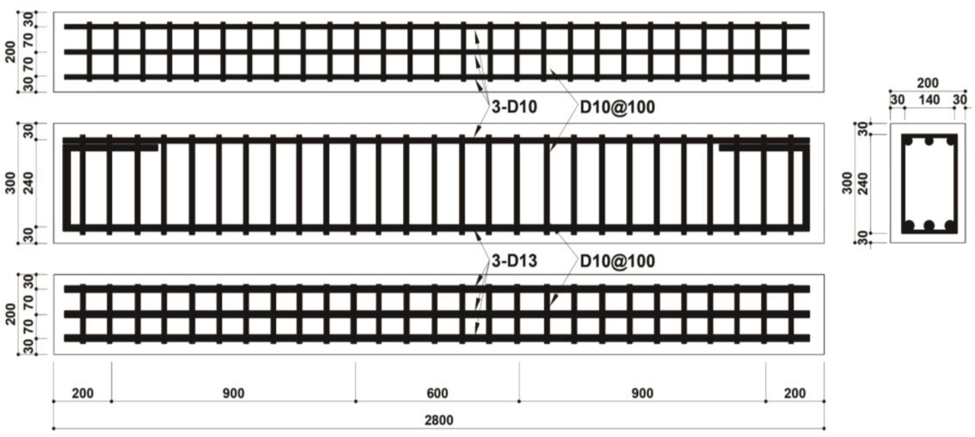
Figure 2.
Electric corrosion method in the case of entire area corrosion.
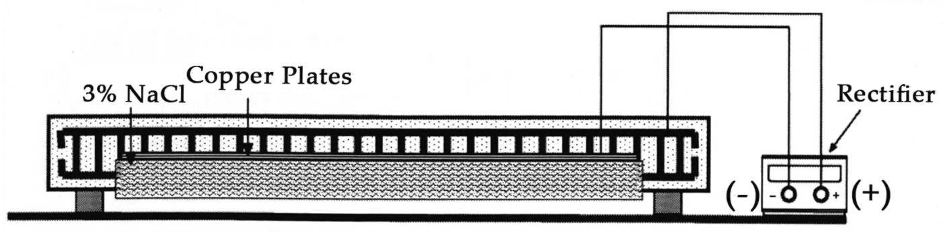
Figure 3.
Electric corrosion method.
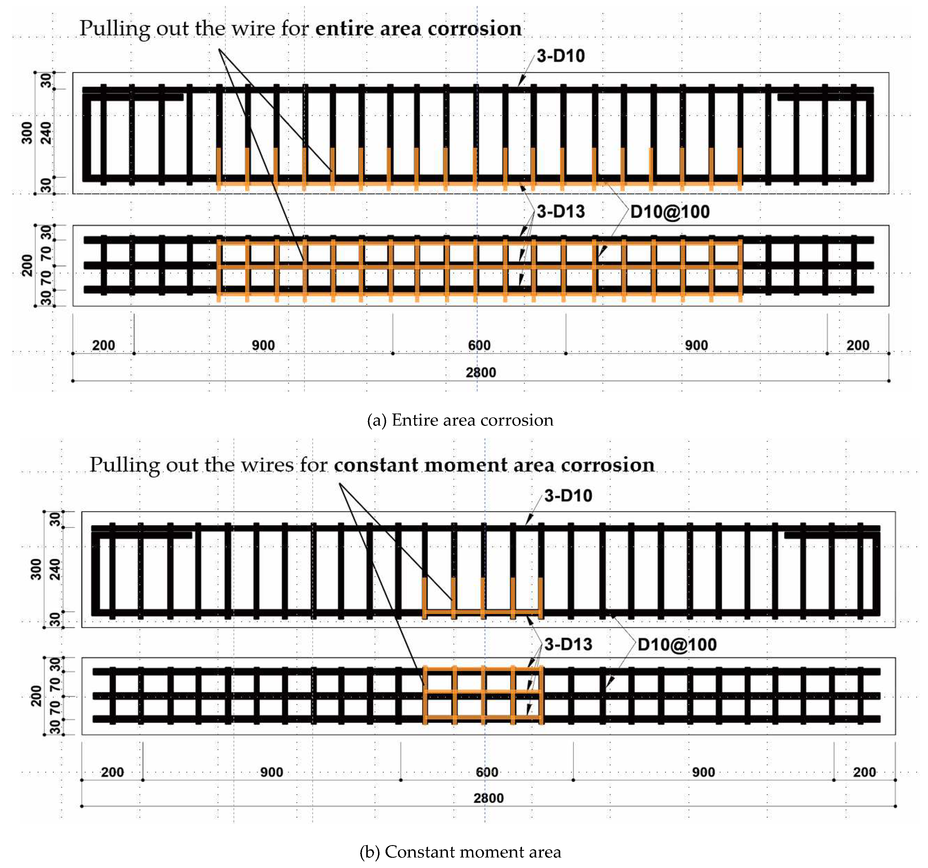
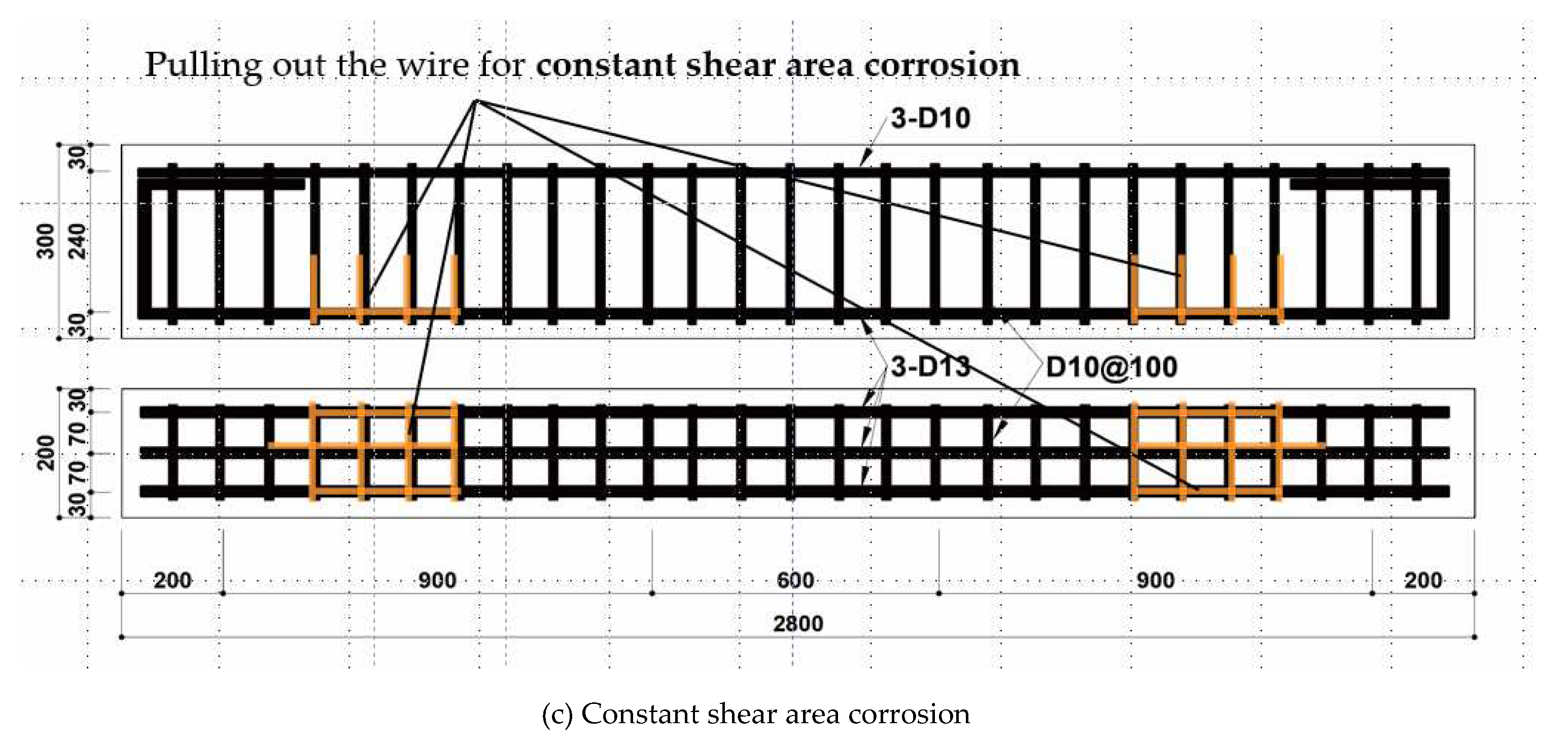
Figure 4.
Loading method and LVDT installation.
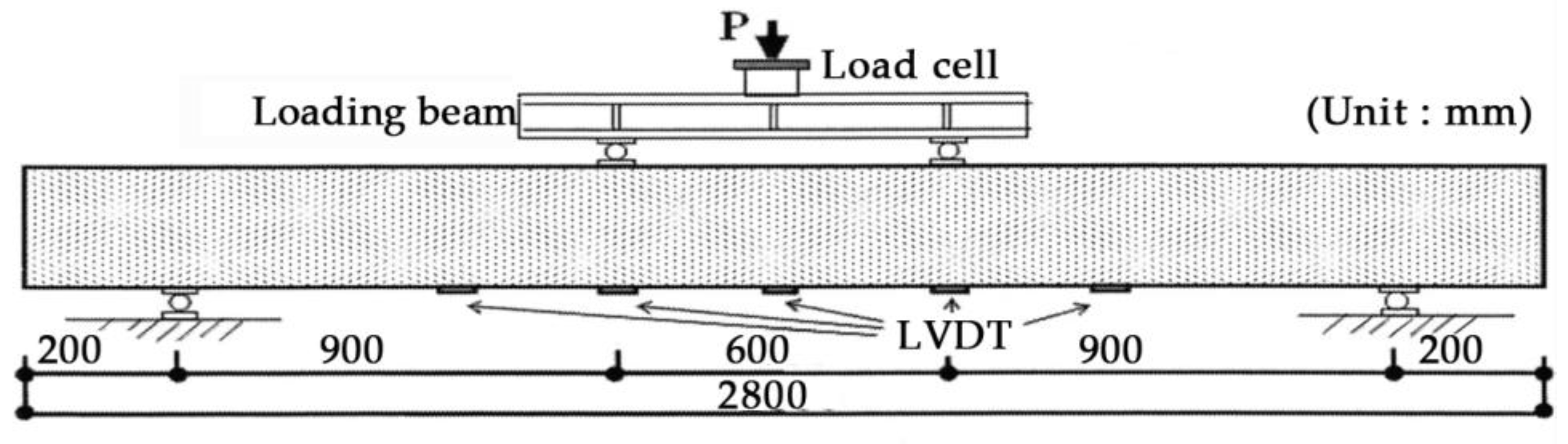
Figure 5.
Photos of the Flexural loading test on the specimen.
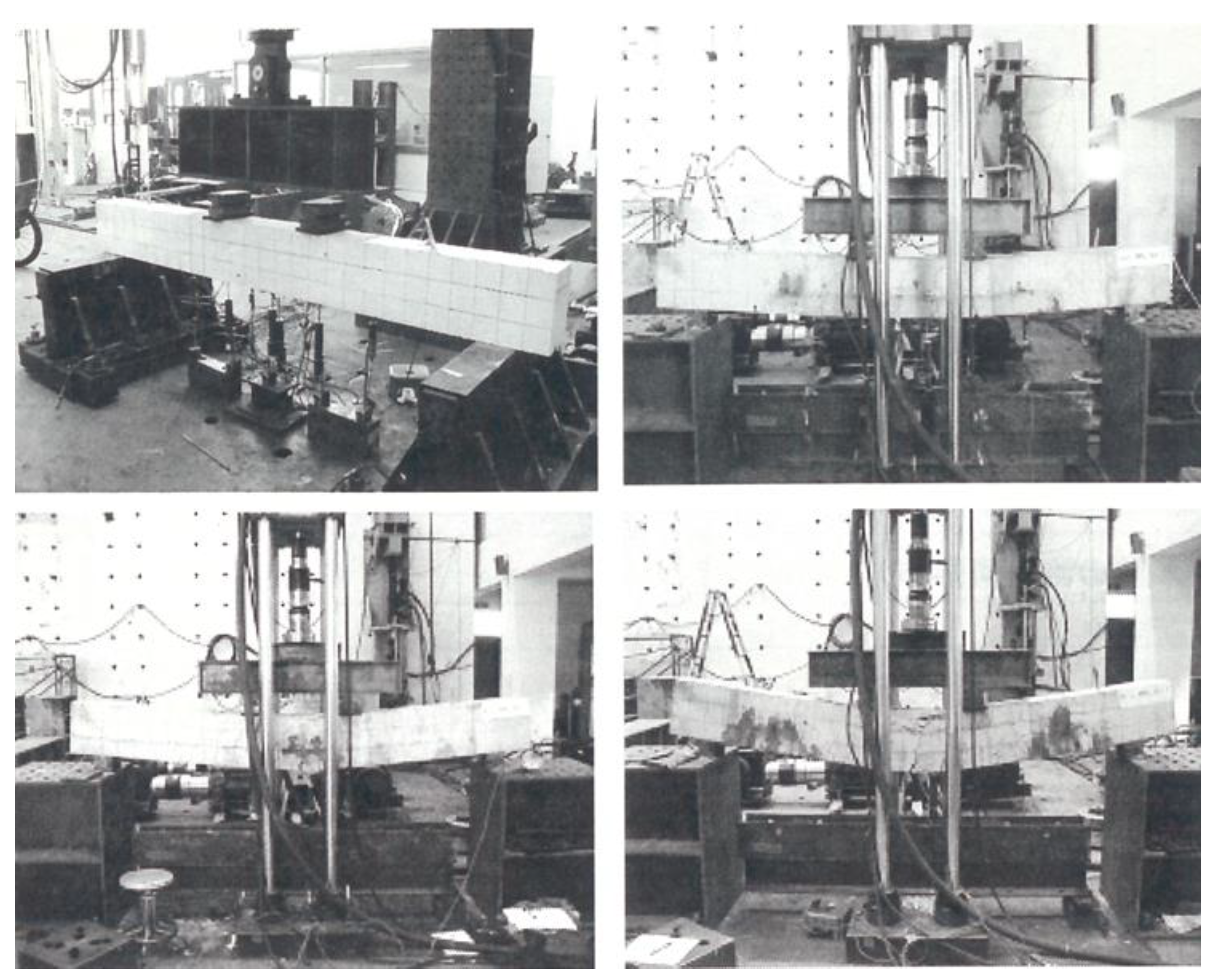
Figure 6.
Deflection of beam versus applied monotonic load.
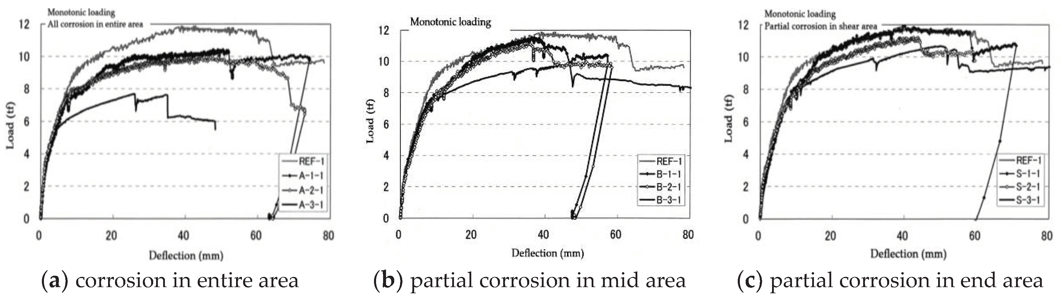
Figure 7.
Corrosion weight loss (%) versus yield and ultimate loads under monotonic loading condition.
Figure 7.
Corrosion weight loss (%) versus yield and ultimate loads under monotonic loading condition.
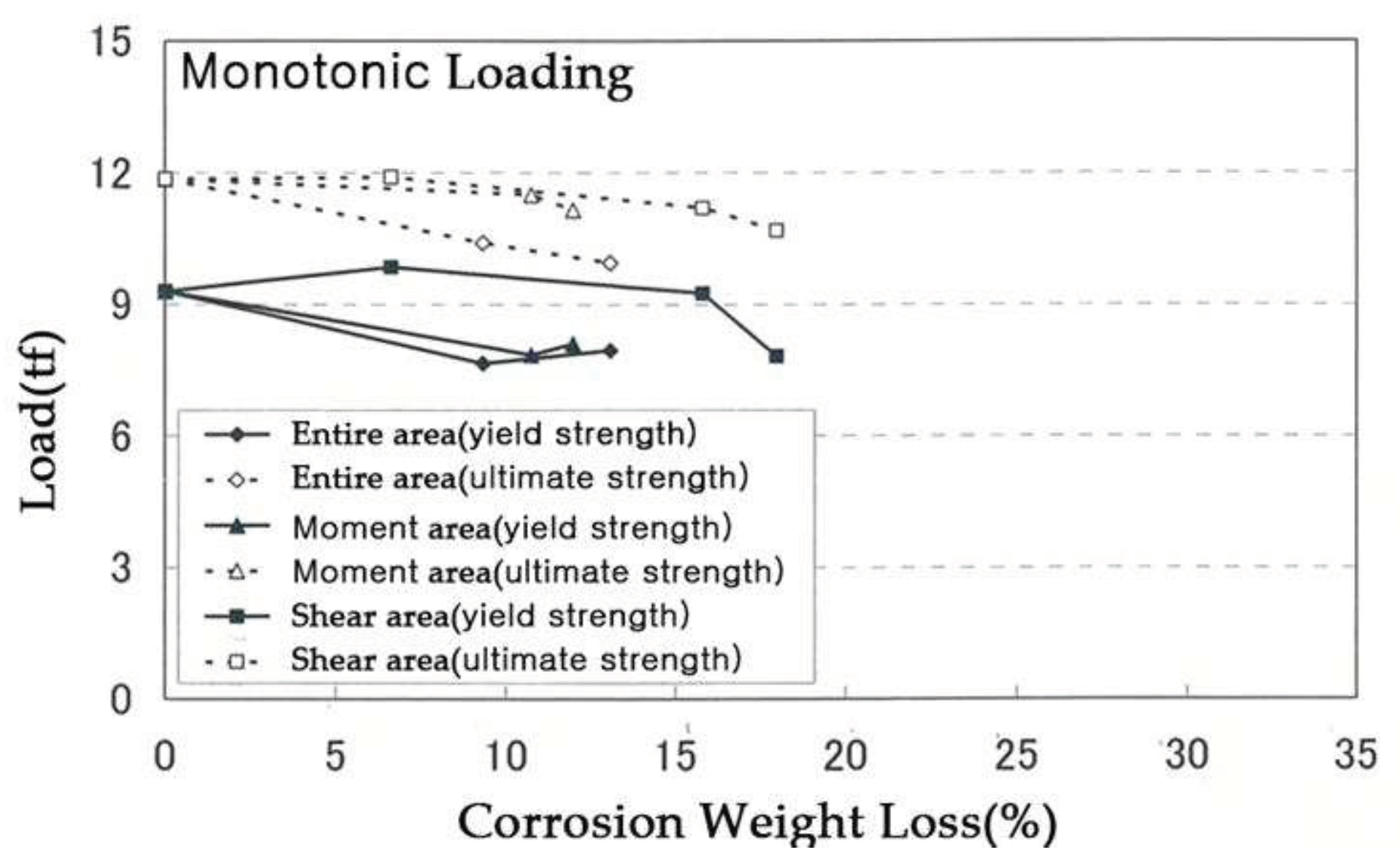
Figure 8.
Corrosion weight loss of rebar measured at 100 mm intervals along the longitudinal direction under monotonic loading condition.
Figure 8.
Corrosion weight loss of rebar measured at 100 mm intervals along the longitudinal direction under monotonic loading condition.
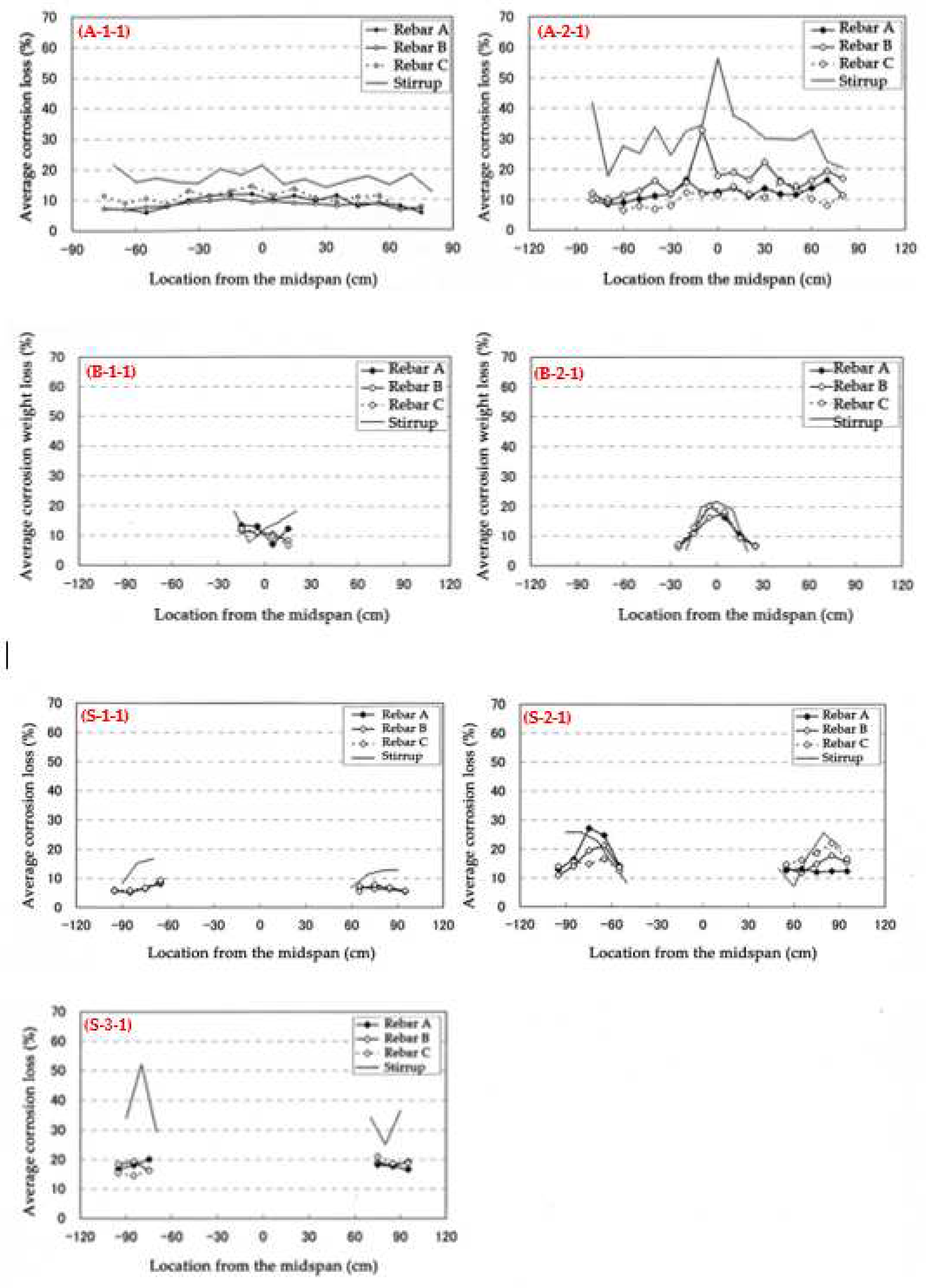
Figure 9.
Distribution of cracks for each specimen under monotonic load.
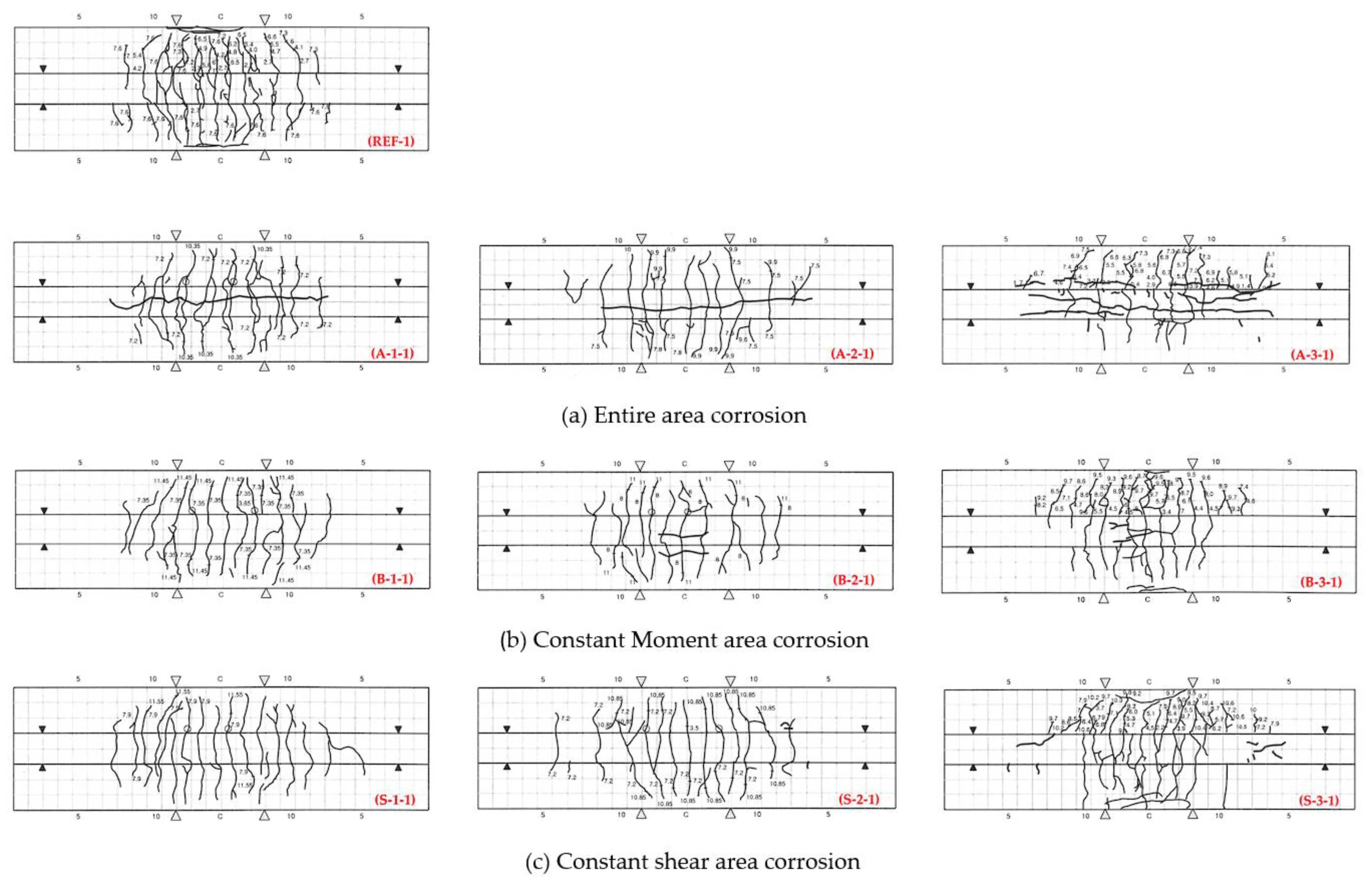
Figure 10.
Deflection of beam versus applied cyclic load.
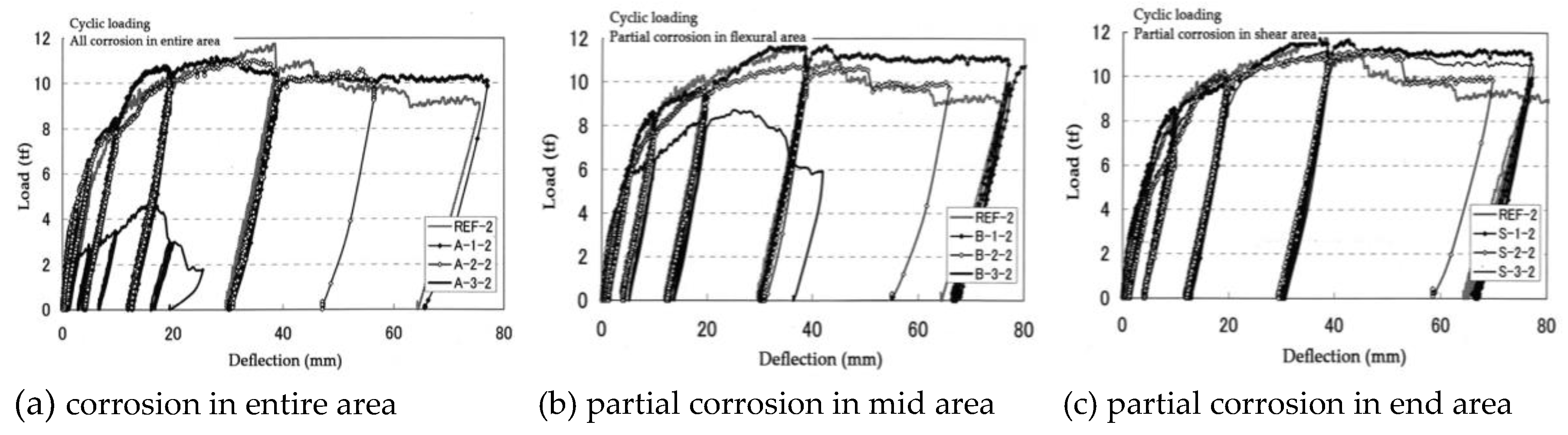
Figure 11.
Corrosion weight loss (%) versus yield and ultimate loads under cyclic loading condition.
Figure 11.
Corrosion weight loss (%) versus yield and ultimate loads under cyclic loading condition.
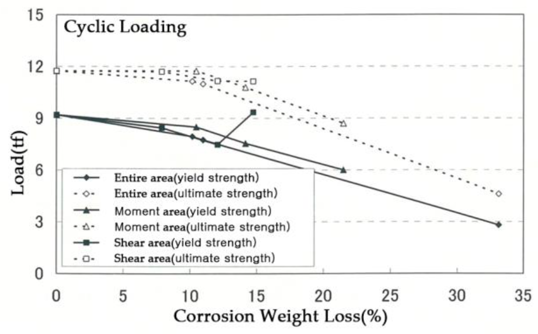
Figure 12.
Corrosion weight loss of rebar measured at 100 mm intervals along the longitudinal direction under cyclic loading condition.
Figure 12.
Corrosion weight loss of rebar measured at 100 mm intervals along the longitudinal direction under cyclic loading condition.
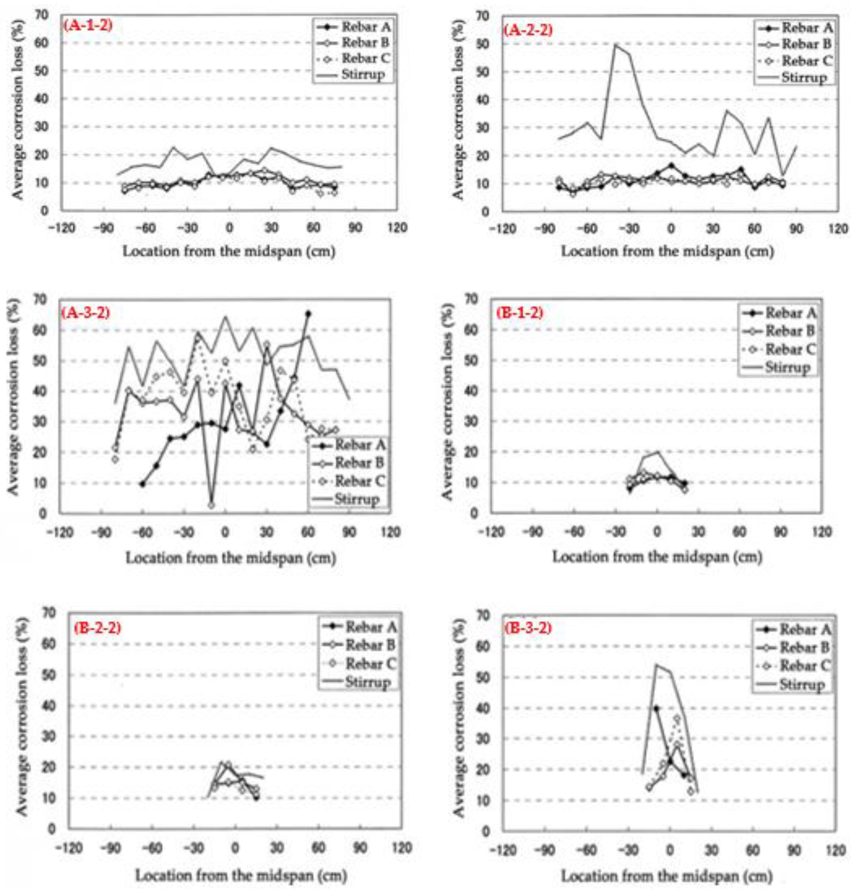
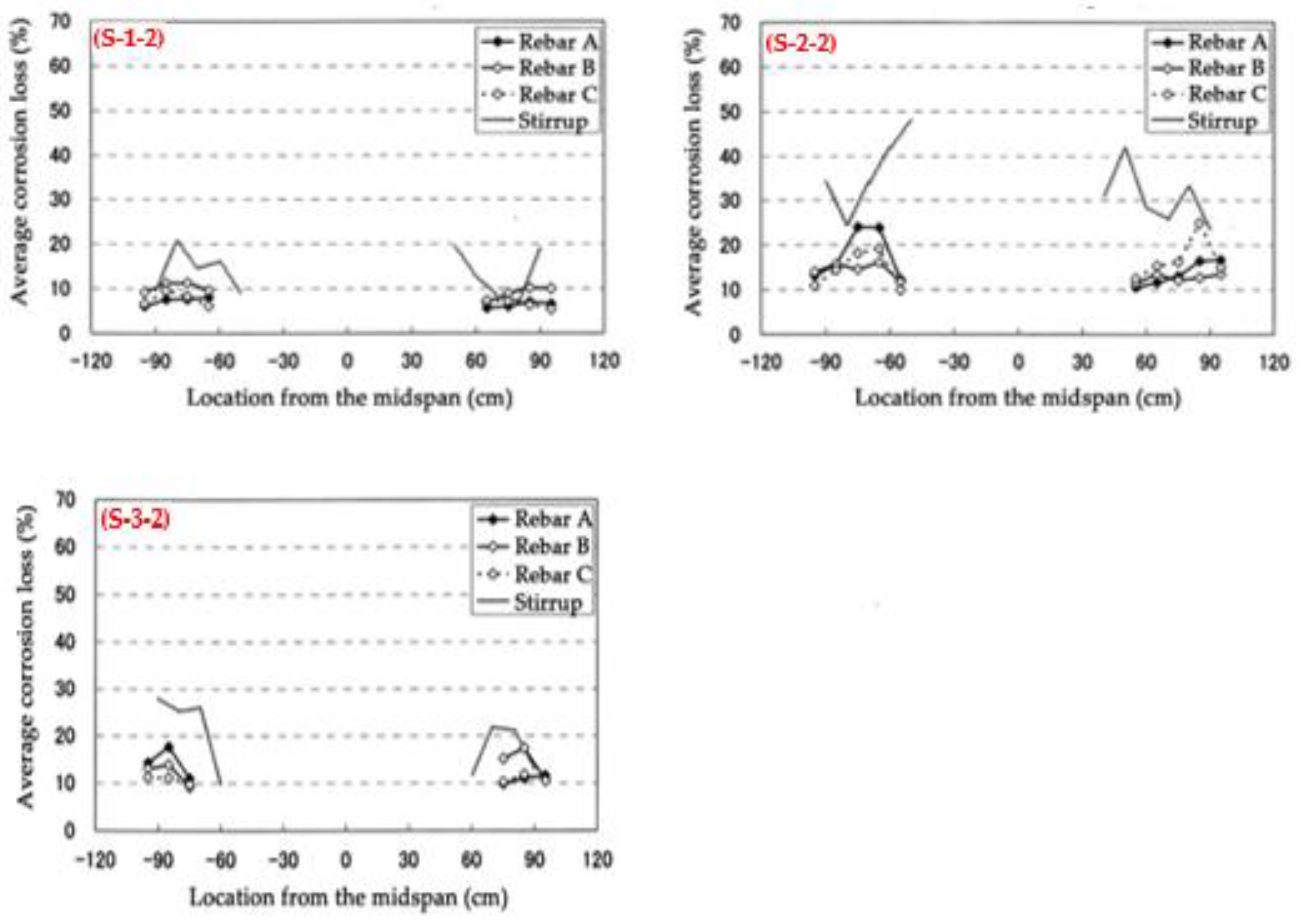
Figure 13.
Distribution of cracks for each specimen under cyclic load.
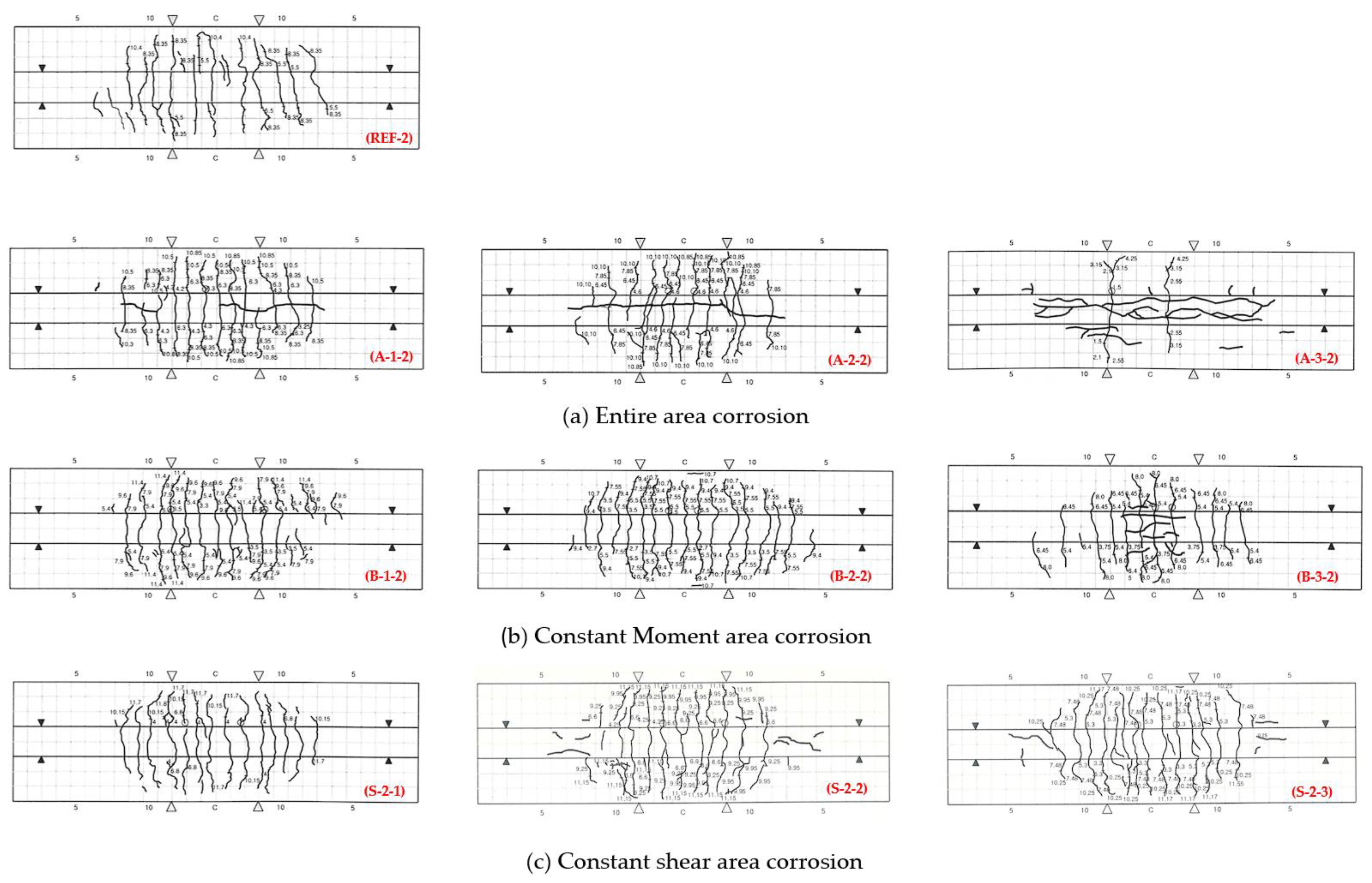

Table 1.
Experimental parameters.
| Test parameters | Types |
|---|---|
| Patterns of rebar corrosion | Corrosion of the entire area (A) |
| Local corrosion in the constant moment area (C) | |
| Local corrosion in the constant shear area (S) | |
| Corrosion level (weight loss) | 5%, 10%, 30% |
| Loading condition | Monotonic loading, Cyclic loading |
Table 2.
Mix proportion and mechanical properties of concrete.
| Cement Type | w/c | s/a | Unit weight (kg/m3) | Slump (mm) | Air (%) | fc’ (MPa) | ft (MPa) | Ec (GPa) | |||
|---|---|---|---|---|---|---|---|---|---|---|---|
| W | C | S | G | ||||||||
| OPC | 0.56 | 48.8 | 174 | 310 | 866 | 926 | 120 | 4.5+1.5 | 21.1 | 2.5 | 21.06 |
Table 3.
Mechanical properties of reinforcement.
| Type of reinforcement | fy (MPa) | fu (MPa) | Es (GPa) | Strain at the yield point | |
|---|---|---|---|---|---|
| D 13 | 412.8 | 589.4 | 180.9 | 177560 | |
| D10 | 371.1 | 545.3 | 216.3 | 191480 | |
Table 4.
Corrosion weight loss and mechanical test results of beam specimens.
| Loading condition | Pattern of rebar corrosion | Specimen name | Corrosion weight loss (wt%) | Yield load (tf) | Max. Load (tf) | deflection at yield load (mm) | deflection at maximum load (mm) | |
|---|---|---|---|---|---|---|---|---|
| average | maximum | |||||||
| Monotonic loading | reference | REF-1 | 0.00 | 0.00 | 9.30 | 11.86 | 10.43 | 39.03 |
| entire area | A-1-1 | 9.33 | 11.71 | 7.65 | 10.40 | 8.70 | 50.36 | |
| A-2-1 | 13.09 | 18.96 | 7.95 | 9.95 | 8.60 | 45.80 | ||
| A-3-1 | - | - | 5.57 | 7.69 | 4.46 | 25.66 | ||
| constant moment area | B-1-1 | 10.76 | 12.58 | 7.85 | 11.50 | 9.40 | 36.16 | |
| B-2-1 | 11.99 | 19.01 | 8.10 | 11.15 | 9.98 | 34.40 | ||
| B-3-1 | - | - | 7.04 | 9.77 | 7.10 | 45.54 | ||
| constant shear area | S-1-1 | 6.63 | 8.81 | 9.85 | 11.90 | 15.96 | 40.16 | |
| S-2-1 | 15.81 | 20.90 | 9.25 | 11.20 | 14.81 | 43.82 | ||
| S-3-1 | 17.98 | 19.47 | 7.81 | 10.68 | 9.29 | 43.84 | ||
| Cyclic loading | reference | REF-2 | 0.00 | 0.00 | 9.20 | 11.75 | 12.01 | 38.40 |
| entire area | A-1-2 | 10.17 | 13.31 | 7.95 | 11.15 | 8.15 | 27.91 | |
| A-2-2 | 10.98 | 13.19 | 7.75 | 11.00 | 7.67 | 34.78 | ||
| A-3-2 | 33.13 | 43.46 | 2.80 | 4.60 | 4.84 | 15.37 | ||
| constant moment area | B-1-2 | 10.47 | 11.93 | 8.50 | 11.75 | 8.92 | 37.13 | |
| B-2-2 | 14.17 | 16.87 | 7.55 | 10.80 | 8.47 | 36.23 | ||
| B-3-2 | 21.49 | 25.57 | 6.00 | 8.70 | 6.07 | 24.73 | ||
| constant shear area | S-1-2 | 7.89 | 9.49 | 8.45 | 11.70 | 8.92 | 37.13 | |
| S-2-2 | 14.75 | 19.68 | 9.35 | 11.15 | 14.41 | 44.12 | ||
| S-3-2 | 12.06 | 14.25 | 7.48 | 11.17 | 7.91 | 39.86 | ||
Disclaimer/Publisher’s Note: The statements, opinions and data contained in all publications are solely those of the individual author(s) and contributor(s) and not of MDPI and/or the editor(s). MDPI and/or the editor(s) disclaim responsibility for any injury to people or property resulting from any ideas, methods, instructions or products referred to in the content. |
© 2023 by the authors. Licensee MDPI, Basel, Switzerland. This article is an open access article distributed under the terms and conditions of the Creative Commons Attribution (CC BY) license (http://creativecommons.org/licenses/by/4.0/).
Copyright: This open access article is published under a Creative Commons CC BY 4.0 license, which permit the free download, distribution, and reuse, provided that the author and preprint are cited in any reuse.


