Submitted:
21 August 2023
Posted:
22 August 2023
You are already at the latest version
Abstract
The practical necessity of strengthening of reinforced concrete structure elements requires a choice of a method which would provide cost-effectiveness, simplicity of construction and durability of the chosen solution. One of the ways is strengthening using the material belonging to the group of micro-reinforced concretes called ferrocement. The paper presents the comparative analysis of some of the results of RC beams exposed mainly to flexure, strengthened with ferrocement elements (strips) applied by gluing on the on the tensed side of RC beams. The results are obtained using the experimental, analytical and numerical research on the adequate models. Strengthening of the beams was performed in the form of four types of ferrocement strips (four different strip widths and four different numbers of wire mesh layers). The numerical non-linear analysis using finite elements method (FEM) was employed, with the introduction of the corresponding characteristics of constitutive material obtained by the experiments on the test specimens. The analytical researches were performed using known analytical calculation methods in order to formulate the model for the calculation of the ultimate and serviceability limit states of the strengthened cross-section. The results presented in the paper, through their comparative compatibility, confirmed the applicability of this strengthening method.
Keywords:
strengthening
; micro-reinforced concrete
; ferrocement
; RC beams
; flexure
; numerical simulation
1. Introduction
The need for strengthening of reinforced concrete structures is a topical issue. The goal of the strengthening is to obtain the structure capable of meeting the service and durability requirements, in accordance with the technical regulations. The choice of the solutions (strengthening) depends on several factors, whereby it is most important to achieve cost-effectiveness, simplicity of construction and durability of the chosen design. One of the ways is strengthening using the material belonging to the group of micro-reinforced concretes called ferrocement. Ferrocement is characteristic for made with a cement-based mortar matrix reinforced with closely spaced layers of small diameter wire mesh.
A very important fact is that along with the excellent properties (outstanding durability, strength, toughness, watertightness, resistance to aggressive environment, easy shaping and construction), it is also compatible with all other cement based composites and the theoretical approach to the design is not different from the conventionally reinforced concrete. Also, the attention is paid to the quality connection between the conventional and micro-reinforced concrete, as well as on the stress-strain analysis of strengthened RC beams.
There is a number of scientific papers concerned with the mentioned issues. Numerous solutions for strengthening different RC structural elements using ferrocement were proposed: the potential for strengthening RC columns by “confining” them using ferrocement to wrap them around [1,2,3], strengthening RC slabs in the tensioned zone [4], strengthening of the rigid RC column and RC beam joint [5]. High-strength cement matrixes were tested [6], as well as the use of ferrocement with the combined continuous and discontinuous micro-reinforced, exposed to flexure [7]. Behavior of U-cross-section beams made of ferrocement exposed to flexure was researched [8]. Majority of scientific papers discusses the strengthening of RC beams using ferrocement. Considering that the beams are prevalently exposed to flexure and shear, several structural strengthening propositions were made. Some authors tested the behavior of RC beams strengthened with ferrocement by direct application of micro-reinforcement mesh and cement matrix on the previously prepared concrete surface [9,10,11], with the use of steel connectors. A different approach is the making of U-cross-section ferrocement elements, which are simultaneously the formwork for construction of RC beams [12]. RC beams of lightweight concrete or low strength concrete were strengthened by the complete “confinement” using ferrocement [13,14]. The approach to strengthening by “gluing” ferrocement on the reinforced concrete was used by some authors [15,16]. An interesting approach was the research of ferrocement strengthening of predamaged RC beams [17,18].
The paper researches the situation of strengthening RC beams primarily exposed to flexure by applying the prefabricated ferrocement elements of small thickness. The binding (gluing) agent chosen was the adhesive epoxy-mortar applied in a thin layer on the RC beam and on the ferrocement element immediately before the joining. For this procedure, no special treatment of the concrete and ferrocement is necessary, except that all the surfaces are dry, clean and undamaged. The idea is to simulate the strengthening of the existing RC beams in practice, especially if they are not easily accessible.
Also investigated is the potential of the use of some generally known calculation methods, as well as the comparison of analytical with experimental and numerical results.
2. Theoretical basis of the calculation and analytical, experimental and numerical modeling of RC beams strengthened with ferrocement
The analysis of strengthened composite beams requires knowing relations between the stress and strain of all constituent materials (concrete, conventional reinforcement, mortar, micro-reinforcement, and adhesive epoxy-mortar). The problem is complex because of the large number of parameters making the calculation difficult. Some suitable analytical methods, with certain simplifications, can be employed.
If the composite cross-section exposed to service loads in the phase of linear elastic behavior to first matrix cracking are analyzed, it is convenient to use the flexure formula for uncracked section, while for the cracked sections is suitable the transformed area method for the cracked section [19].
The calculation of the nominal bending resistance provides the value of the bending moment at failure (nominal bending moment). Compatibility method, simplified method based on all tensile reinforcement yielding, simplified method using plastic moment [19] can also be used.
For the requirements of the comparative analysis of the experimental model results, the transformed area method for the cracked section is used. The linear theory is used to determine flexural tensile stress due to service loads, with the following assumptions:
- strains change linearly with the distance from the neutral axis.
- stress-strain relation is linear for mortar, concrete, micro-reinforcement, and reinforcement, for the stresses lower or equal to the permissible operational stresses.
- mortar and concrete do not resist tension.
- ideal adhesion between mortar and micro-reinforcement, i.e., concrete and conventional reinforcement is achieved.
Elastic moduli ratio is presented by the following expressions:
- cross-sectional area of concrete
- cross-sectional area of reinforcement of layer i
- cross-sectional area of adhesive epoxy-mortar
- cross-sectional area of cement matrix
- cross-sectional area of micro-reinforcement of layer i
- cross-sectional area of reinforced concrete
- cross-sectional area of ferrocement strip
The neutral axis of bending of the transformed cracked section (c):
Summing on the left side of the expression is used for the layers of reinforcement which are in the compression zone, while the summing on the right side relates to the layers of reinforcement mesh in the tensile zone. After obtaining the neutral axes (c) position, the moment of inertia of the cracked transformed section can be calculated:
After defining the characteristics of the observed cross-section, the stresses in any fiber can be calculated with the use of the flexure formula:
for . A positive value for the stress implies tension and a negative value implies compression.
From the flexure maximum allowable service moment can be calculated, whereby according to Naaman [19] and Ferrocement Model Code, Building Code Recommendations for Ferrocement [20], the following is recommended:
- Tensile stress in reinforcement due to the service load caused by tension, bending or their combination, should not exceed the value of 0,60·fy (fy - yield strength of the reinforcement), nor the value of 400MPa. The limitation of 400MPa can be increased in the case of use of high strength reinforcement meshes, if their effect is experimentally proven.
- The maximum compressive stress in the mortar matrix under bending should not exceed the value of 0,45·fc’ (fc’- specified design compressive strength, obtained by examining the test cylinders).
Calculation of bending of strengthened RC beam and of the control RC beam were performed on the calculation models which were fully harmonized with the test experimental models. In Figure 2 is presented the choice of geometry of the control (non-strengthened) RC beam.
The procedure in which the prefabricated ferrocement elements are applied to the bottom (tensioned) zone of an RC beam was chosen as a strengthening method of an RC beam with ferrocement (Figure 3). The choice of the method guarantees a simple and rapid procedure of “fitting” the strengthening elements. The “glue” is applied on the concrete and ferrocement, and then the mentioned elements are joined. This is a very favorable approach to the strengthening of beams in practice, especially if it is difficult to access the RC beams. Joining the reinforced concrete and ferrocement was accomplished with the adhesive epoxy-mortar “SX 481 E” of the renowned German manufacturer “MC-Bauchemie” [21] (Figure 4).
In Figure 5 the cross-section of four types of ferrocement elements prepared for strengthening of RC beams is presented. The used micro-reinforcement is the electro-welded mesh steel galvanized wire Ø0,6mm with the mesh openings 12,5/12,5mm. The thickness of ferrocement elements and number of micro-reinforcement layers was varied (Table 1):
Table 2 shows the mechanical properties of concrete, conventional reinforcement, adhesive epoxy-mortar, cement matrix and micro-reinforcement. On the basis of their values, the calculation of bending of RC beams strengthened with ferrocement strips was performed.
Experimental research of the test models of beams loaded to bending were carried out in the laboratory conditions. The RC beam types strengthened with ferrocement strips, as well as control (non-strengthened) beams were constructed in full agreement with the previously stated data in Figures 2, 3, 5 and they possess mechanical properties provided in Table 1. The RC beams were made in a standard way, in metal formwork, and the making of ferrocement elements is presented in Figure 6.
Application of ferrocement strips on the RC beams is shown in Figure 7.
The schematic diagram of RC beam loaded with two concentrated forces („Four Points Load“) is shown in Figure 8(a), while in Figure 8(b) is shown the layout of one of the tested experimental models.
Structural elements made of composite materials (cement-based composites) require a complex analysis, precisely because of the existence of numerous factors that influence the behavior of the beams. The different physical and mechanical characteristics of the constituent materials, the degree of realized mutual connections of the components, the linearity and non-linearity of the behavior of the components during the loading of the beam, are the reason why it is difficult to produce analytical expressions that reliably depict all states of load-bearing capacity and serviceability. In order to qualitatively solve such a problem, it is necessary to apply a specific numerical procedure.
Numerical analysis of non-strengthened and strengthened experimental models was performed using the finite element method (FEM) with the help of the ANSYS software package (a program for static, dynamic, linear and nonlinear analysis of structures). Monitoring the behavior of experimental supports under load using numerical models is one of the most complex tasks in the application of FEM, considering the number and diversity of the characteristics of the constituent materials of such composites (Figure 9).
2.4.1. Adopted characteristics of constitutive materials
It is generally known that concrete, as a structural material, exhibits different characteristics under compression and under tension. The tensile strength is many times lower than the compressive strength. Numerical modeling of concrete is thus rendered complex. For the purposes of numerical simulation of experimental models, the following parameters were adopted to define concrete in the ANSYS software package [22]:
Ec - modulus of elasticity of concrete
fc’ - ultimate strength at uniaxial compression
fr - ultimate strength at uniaxial tension
ν - Poisson’s ratio
βt - shear transfer coefficient
Multilinear (polygonal) stress-strain curve [23] was introduced as a simplified substitution for the nonlinear stress-strain relation at uniaxial compression (Figure 10). It is constructed using six points, with the goal of assisting in convergence of the nonlinear solution of the algorithm. Characteristic points of the multilinear curve are calculated in the way presented in Table 3.
The parameter values for the formation of the multilinear curve were calculated based on the experimental data obtained on the test specimens. The quasi-brittle behavior of the concrete of the experimental beam models was simulated with this procedure.
Steel (conventional) reinforcement is modeled as an elastic-ideally plastic isotropic material. The properties of steel in compression and tension are treated as identical.
RC beams strengthened with ferrocement are constantly in the tensioned zone of the cross-section. In any phase of the load, the entire ferrocement cross-section is in tension, removed from the neutral axis and possesses very small thickness in comparison with the dimensions of the RC beam. Cement matrix is treated as a brittle-elastic. The term “brittle” denotes the linear-elastic behavior of the matrix exposed to tension, which continues up to the moment of cracking (discontinuation) of the matrix [19]. After exceeding the maximum tensile stress, there is no load bearing capacity of the matrix any longer.
Micro-reinforcement (steel mesh), fitted in the ferrocement is modeled as elastic-ideally plastic isotropic material. Micro-reinforcement, as well as the cement matrix is constantly in the tensioned zone of the beam.
The adhesive epoxy-mortar in the numerical model was treated similarly to the cement matrix of ferrocement. The position of the adhesive epoxy-mortar in the cross-section of the beam (always in the tensioned zone), as well as its small thickness, are the reason why it is treated as a brittle-elastic material.
Characteristic values, required for models of constitutive materials (Table 2), were adopted on the basis of experimental data obtained on test specimens, as well as of the manufacturer's declaration.
During the simulation of experimental beam models, a division to finite elements was chosen, whose maximum dimension (depending on the type of the finite element) does not exceed 25mm. Dimensions of the finite elements of constitutive materials are presented in Table 4.
3. Results and discussion
3.1. Experimental test results
3.1.1. Failure mechanism of control (non-strengthened) RC beams
All the examined type K beams (non-strengthened RC beams) exhibited the failure in the same manner – after the elastic behavior phase and compatibility of strains in the tensioned concrete and tensioned reinforcement, with the increase of the load, cracks are formed on the beams, especially in the middle third of the span (zone of the maximum bending moment). The force which causes the yielding of the reinforcement introduces the experimental models into a phase of extreme nonlinear behavior (abrupt increase of cracks and deflections, exceeding the stress in the compression zone, and crushing of concrete). After reaching the nominal force, an uncontrolled increase of deflection occurs, dominant cracks develop into fissures and concrete crushing propagates in the compressed zone, without further increase of the force on the press. This moment is treated as the failure of load bearing capacity, i.e. the beam failure (Figure 12). Control beams have evenly distributed cracks, and the failure is ductile.
3.1.2. Failure mechanism of strengthened RC beams
All strengthened experimental models in the initial phase of loading exhibited elastic behavior, and the cracks in concrete started to form mostly in the middle third of the span. The force which causes the yielding of the reinforcement introduces the experimental models into a phase of extreme nonlinear behavior. Simultaneously, ferrocement reinforcement which acts jointly with RC beams as a unitary, composite section, exits the elastic behavior zone sooner than the reinforced concrete part of the beam. The start of the nonlinear behavior of ferrocement strips is reflected in the formation of a micro-cracks web pattern. In this interval, in the zone of maximum bending (middle third of the span) of the beam, several visible cracks on ferrocement are formed. One of them becomes dominant, so the micro-reinforcement layers fail in the crack. After yielding of micro-reinforcement, there is an accelerated propagation of the dominant crack into a fissure, and a complete failure of strengthened experimental models. As opposed to the control, non-strengthened RC beams, compression stresses in the strengthened models are not exceeded and no cracking and crushing of concrete in the compressed zone is observed. The moment of failure of micro-reinforcement layers is considered the failure moment, i.e. the failure of the load bearing capacity of the model. All the examined strengthened beams exhibited the failure of load bearing capacity in the same way (Figure 13) and always in the zone of maximum bending moments (middle third of the span).
3.1.3. Experimental results of ultimate deflection
Special attention in the analysis of experimental results is devoted to deflections. The behavior of beams under load can be most clearly considered by monitoring the deflections that combine the influence of load, geometry and material (stiffness). Figure 14 shows the characteristic deflection diagrams, measured at middles of the spans of all types of experimental models.
Figure 15 shows a comparative diagram of the characteristic maximum deflections at the moment of failure of strengthened beams of all types, compared with the deflection of control beams. At the load that causes the failure of non-strengthened beams, the maximum deflections of strengthened beams are twice smaller than the maximum deflections of non-strengthened - control beams.
3.1.4. Experimental results of ultimate load capacity
Based on the experimental results, the ultimate load capacities of all types of beams are presented (Figure 16).
3.2 Analytical values of flexural strength of RC beams
In accordance with the previous statements, an analytical calculation of the adopted types of RC beams strengthened with ferrocement elements glued onto the tensed side of the beams, as well as on the control (non-strengthened) RC beam.
The implementation of the transformed area method for the cracked section, provided the maximum service bending moment. In Table 5 are shown the values for all types of beams, whereby the K type is a designation for the non-strengthened (control) RC beam.
Based on the service bending moment (from the condition σs,max=0,6·fsy) the ultimate bending moment can be defined using the partial safety coefficient (Mu=γ·Mservice).
For the reinforced concrete, the recommended partial safety coefficient of the variable actions according to Eurocode 2 – Part 1-1 [24] is 1,5. The recommended value for ferrocement according to ACI 318.R-95 [25] is 1,7, while the IFS Committee [20] recommends the value 2.
For the needs of further consideration of the nominal bending moment, 2 variants of the partial safety coefficient were adopted: 1,5 and 1,7.
The nominal bending moment, that is, maximum flexural strength of the structure is defined by the relation Mu≤φ·Mn. The strength coefficient (φ) for the reinforced concrete, recommended by ACI 318.R-95 [25], is also recommended for the ferrocement structural elements, and amounts to φ=0,90 (for the cases of bending and axial tension).
3.3. The results of analysis of numerical models
3.4. Comparative analysis of the results of RC beams in bending strengthened with ferrocement
Table 9 shows the values of the concentrated force that causes the nominal bending moment, and it was calculated using the analytical methods mentioned in Table 8. The intensity of the concentrated force can be reached using the values presented in Figure 8(a). The values are compared with the mean failure force of experimental models of all types, as well as with the failure force obtained by the numerical simulation.
4. Conclusions
Based on the presented method of strengthening of RC beams with prefabricated ferrocement elements and presented analytical, experimental and numerical research, the following conclusions can be made:
- The chosen method of coupling reinforced concrete and ferrocement by gluing is an effective, simple and easily applicable method of strengthening the RC beam to bending. It can be very interesting for inaccessible beams, given that it is constructed quickly and does not require special fitting and curing conditions.
- The bond made with adhesive epoxy-mortar effectively joins the materials and guarantees the joint resistance of reinforced concrete and ferrocement. At the failure of the bearing capacity and the occurrence of fracture of all tested strengthened RC beams, the ferrocement strips remained attached to the reinforced concrete, regardless of their longitudinal failing and loss of the strengthening function.
- Ferrocement obeys the same laws and design principles and is dimensioned according to the same theories as conventionally reinforced concrete. Analytical calculation of reinforced beams according to the mentioned generally accepted theoretical methods showed agreement with the results of experimental research and the results of numerical simulation (Table 9).
- All the mentioned analytical methods can be applied, with the note that the transformed area method for the cracked section gives the service bending moment. For the calculation of the nominal bending moment, it is necessary to first select the appropriate partial safety coefficient. The recommended values of 1.5 and 1.7 define the final calculation results sufficiently well (Table 9).
- Load bearing capacity of the tested strengthened RC beams was 21,14% higher than the non-strengthened beams (Figure 16), all depending on the reinforcement type (thickness of ferrocement strip and number of micro-reinforcement mesh layers).
- Strengthening the RC beams with ferrocement strips had a very favorable effect on the limit state of serviceability. At the load which causes the failure of non-strengthened beams, the values of maximum deflections of tested strengthened beams were 36% to 43% of the maximum deflection of non-strengthened beams (Figure 15).
- The non-linear analysis that used numerical models provided a display of the characteristic phases that the experimental beams went through during load application, but it is extremely demanding due to the large number of input parameters (a large number of different materials and simulation of their interconnections). For this reason, there are certain deviations (Figure 17, Figure 18 and Figure 19), mainly related to the idealization of the physical and mechanical characteristics of the constituent elements of composite beams and their mutual interaction.
- Numerical simulation of non-strengthened and strengthened models provides the values of the failure force for strengthened and non-strengthened beams which are in good agreement with the experimentally and analytically obtained values (Table 9).
References
- Xiong, G.J.; Wu, X.Y.; Li, F.F.; Yan, Z. Load Carrying Capacity and Ductility of Circular Concrete Columns Confined by Ferrocement Including Steel Bars, Construction and Building Materials, 2011, 25, 2263-2268. [CrossRef]
- Mourad, S.M.; Shannag, M.J. Repair and Strengthening of Reinforced Concrete Square Columns using Ferrocement Jackets, Cement & Concrete Composites, 2012, 34, 288–294. [CrossRef]
- Kaish, A.B.M.A.; Jamil, M.; Raman, S.N.; Zain, M.F.M. Axial Behavior of Ferrocement Confined Cylindrical Concrete Specimens with Different Sizes, Construction and Building Materials, 2015, 78, 50-59. [CrossRef]
- Al-Kubaisy, M.A.; Jumaat, M.Z. Flexural Behaviour of Reinforced Concrete Slabs with Ferrocement Tension Zone Cover, Construction and Building Materials, 2000, 14, 245-252. [CrossRef]
- Li, B.; Lam, E.S.; Wu, B.; Wang, Y. Experimental Investigation on Reinforced Concrete Interior Beam–Column Joints Rehabilitated by Ferrocement Jackets, Engineering Structures, 2013, 56, 897-909. [CrossRef]
- Shannag, M.J.; Mourad, S.M. Flowable Hhigh Strength Cementitious Matrices for Ferrocement Applications, Construction and Building Materials, 2012, 36, 933-939. [CrossRef]
- Shannag MJ; Ziyyad TB Flexural response of ferrocement with fibrous cementitious matrices. Construction and Building Materials, 2007, 21, 1198–205. [CrossRef]
- Gaidhankar, D.G.; Kulkarni, M.S.; Jaiswal, A.R. Ferrocement Composite Beams under Flexure, International Research Journal of Engineering and Technology (IRJET), 2017, Volume 04 Issue10, 117-124.
- Shang S.P.; Zeng, L.O.; Peng, H. Flexural Strengthening of Reinforced Concrete Beam with Ferrocement, 28th Conference on Our World in Concrete & Structures, Singapore, 28-29 August 2003.
- Makki, R.F. Response Of Reinforced Concrete Beams Retrofitted By Ferrocement, International Journal of Scientific & Technology Research, 2014, Volume 3, Issue 9.
- Zisan, B.; Biswas, B.K.; Hasan, A.; Chanda, M.; Dhar, A. Flexural Performance of Reinforced Concrete Beams Retrofitted Using Ferrocement Wire Mesh, Architecture and Engineering, 2023,Volume 8 Issue 1, 71-81. [CrossRef]
- Fahmy, E.H.; Shaheen, Y.B.I.; Abdelnaby, A.M. Applying the Ferrocement Concept in Construction of Concrete Beams Incorporating Reinforced Mortar Permanent Forms, International Journal of Concrete Structures and Materials, 2014, Vol.8, No.1, pp.83–97. [CrossRef]
- El-Wafa, M.A.; Fukuzawa, K. Flexural Behavior of Lightweight Ferrocement Sandwich Composite Beams, Journal of Science & Technology, 2010, Vol. (15) No.(1) JST 3.
- Miah, M.J.; Miah, M.S.; Alam, W.B.; Lo Monte, F.; Lie, Y. Strengthening of RC beams by ferrocement made with unconventional concrete, Magazine of Civil Engineering, 2019, 89(5), 94-105. [CrossRef]
- Bashandy A.A. Experiments on Flexural Strengthening of Reinforced Concrete Beams using Valid Strengthening Techniques, Acta Technica Napocensis: Civil Engineering & Architecture, 2013, Vol. 56, No. 1.
- Sridhar, J.; Malathy, R.; Sangeetha, R.K. Flexural Strengthening of Reinforced Concrete Beamsusing Ferrocement Laminates with Partial Replacement of Fine Aggregate by Steel Slag, Journal of Engineering and Technology, 2014, Volume 4, Issue 2, 123-126.
- Reddy, M.V.; Reddy, E.M. Rehabilitation of Shear Deficient RC Beams, International Journal of Earth Sciences and Engineering, 2011, Vol. 04, No. 06, pp. 1125-1128.
- Sivagurunathan, B.; Vidivelli, B. Strengthening of Predamaged Reinforced Concrete Beams by Ferrocement Plates, International Journal of Current Engineering and Technology, 2012, Vol.2, No.4.
- Naaman, A.E. Ferrocement & Laminated Cementitious Composites, Techno press 3000, Michigan, USA, 2000.
- IFS Committee 10 Ferrocement Model Code, Building Code Recommendations for Ferrocement (IFS 10-01), Reported by IFS Committee 10.
- https://www.mc-bauchemie.sg/products/concrete-cosmetics/speciality-mortars/sx-481-e.html.
- ANSYS User’s Manual Revision 5.5, ANSYS, Inc. Canonsburg, Pennsylvania, 2006.
- Kachlakev, D.; Miller, T. FE Modeling of Reinforced Concrete Structures Strengthened with FRP Lamiates, Final Report SPR 316, Oregon State University (2001).
- CEN. Eurocode 2: Design of concrete structures - Part 1-1 : General rules and rules for buildings, EN 1992-1-1:2004. European Committee for Standardization, Belgium, 2004.
- ACI 318.R-95 Building Code Requirements for Reinforced Concrete and Commentary, ACI Committee 318, American Concrete Institute, Detroit, 1995.
Figure 1.
Cracked section under bending (linear-elastic composite).
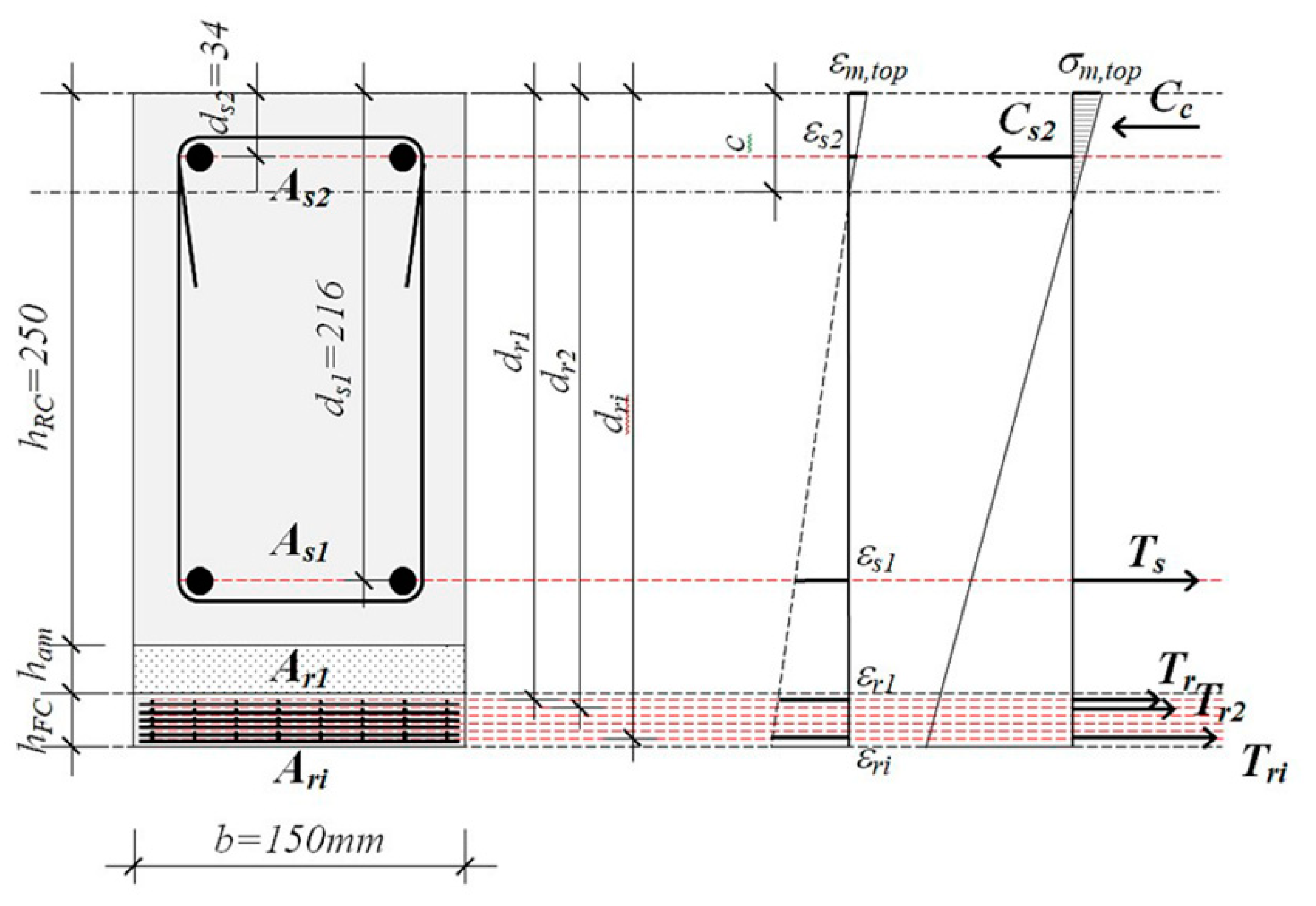
Figure 2.
Choice of geometry of control (non-strengthened) RC beam: (a) Longitudinal section; (b) Cross section.
Figure 2.
Choice of geometry of control (non-strengthened) RC beam: (a) Longitudinal section; (b) Cross section.
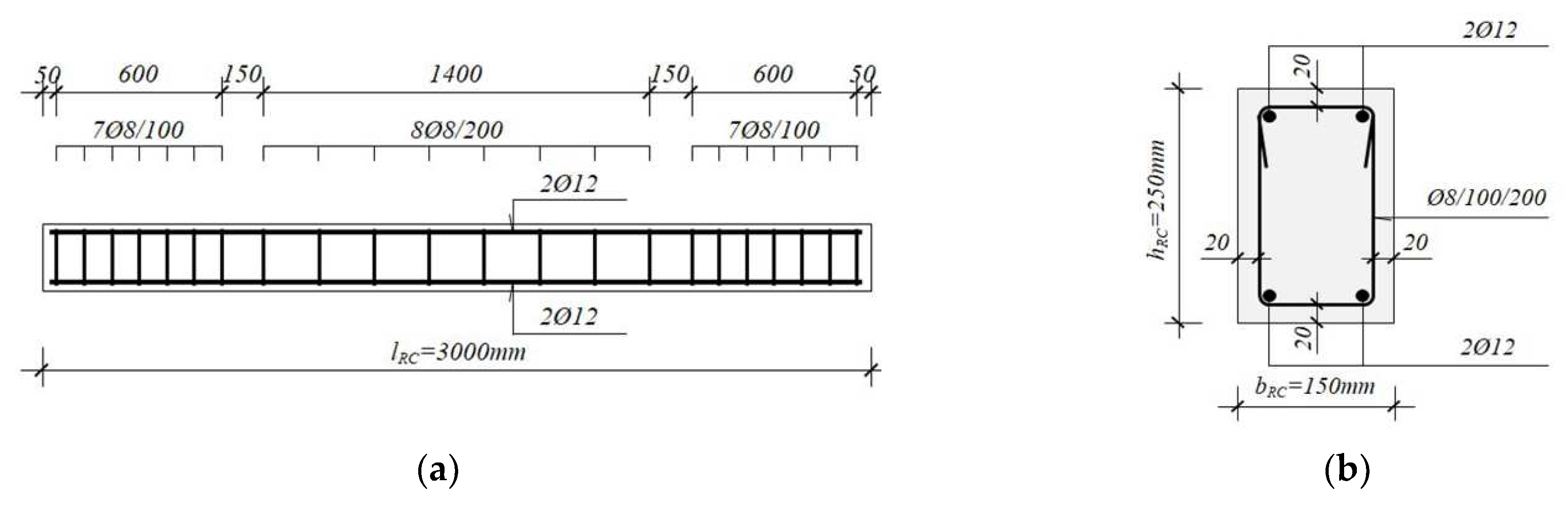
Figure 3.
The method of strengthening of RC beams using ferrocement element: (a) Longitudinal section; (b) Cross section.
Figure 3.
The method of strengthening of RC beams using ferrocement element: (a) Longitudinal section; (b) Cross section.
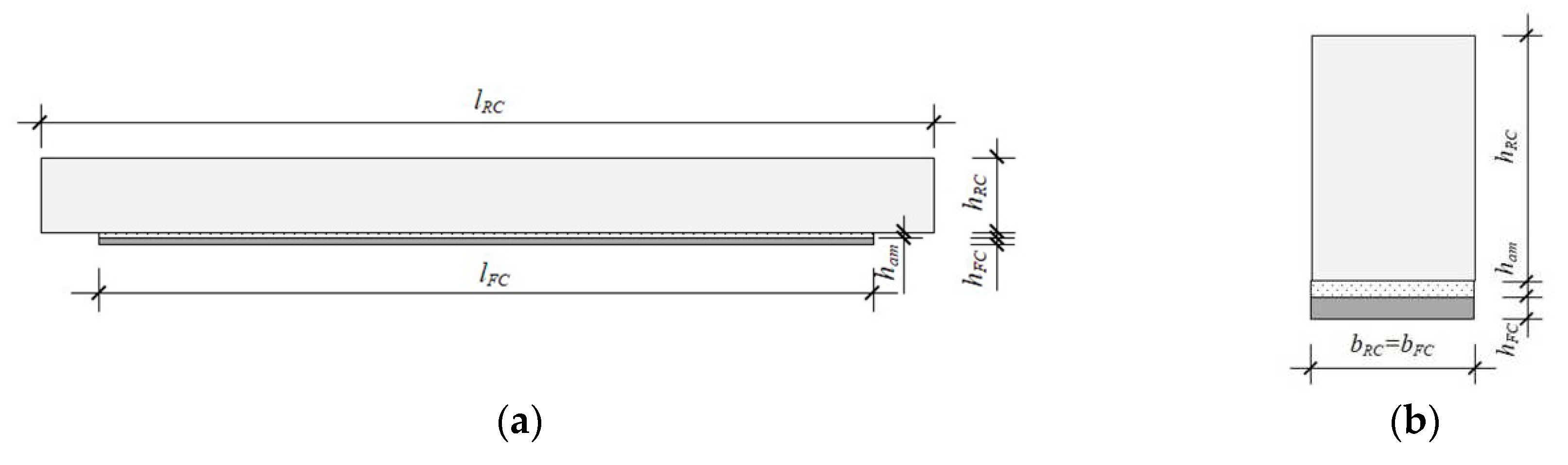
Figure 4.
Adhesive epoxy-mortar “SX 481 E” produced by “MC-Bauchemie” [21].
Figure 4.
Adhesive epoxy-mortar “SX 481 E” produced by “MC-Bauchemie” [21].
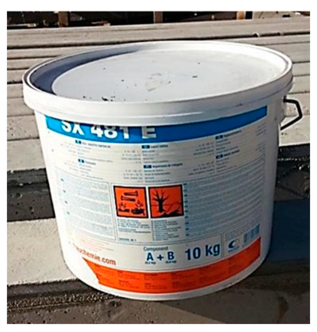
Figure 5.
Cross section of ferrocement strip type I, II, III and IV.
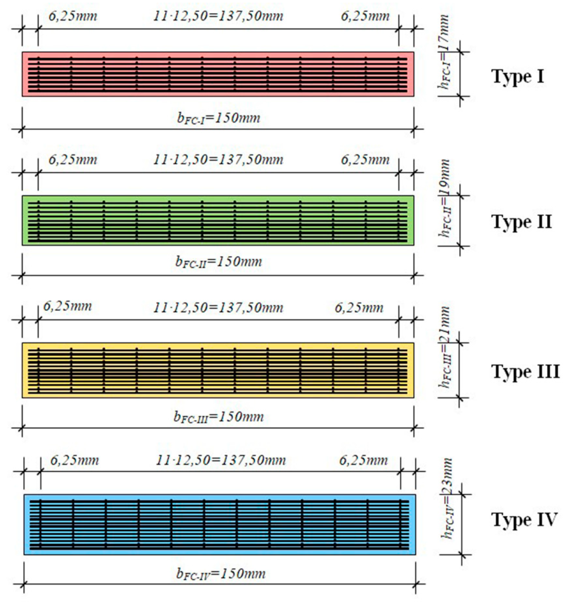
Figure 6.
Making of ferrocement elements: (a) Applying cement mortar in the formwork; (b) Pouring of the matrix by “injection“ along with formwork vibration.
Figure 6.
Making of ferrocement elements: (a) Applying cement mortar in the formwork; (b) Pouring of the matrix by “injection“ along with formwork vibration.
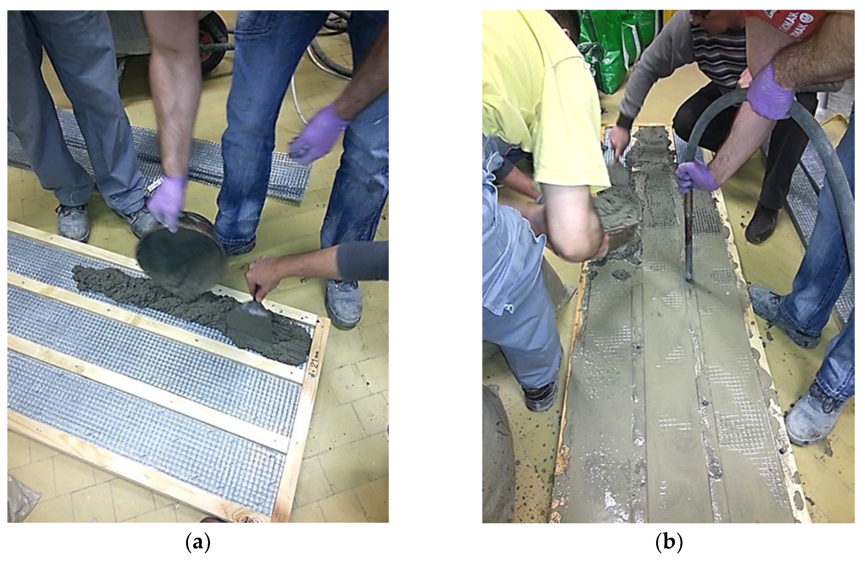
Figure 7.
Application of ferrocement strips on the RC beams: (a) Application of epoxy-mortar on RC beam and ferrocement strip; (b) Removal of excess epoxy-mortar from the joint.
Figure 7.
Application of ferrocement strips on the RC beams: (a) Application of epoxy-mortar on RC beam and ferrocement strip; (b) Removal of excess epoxy-mortar from the joint.
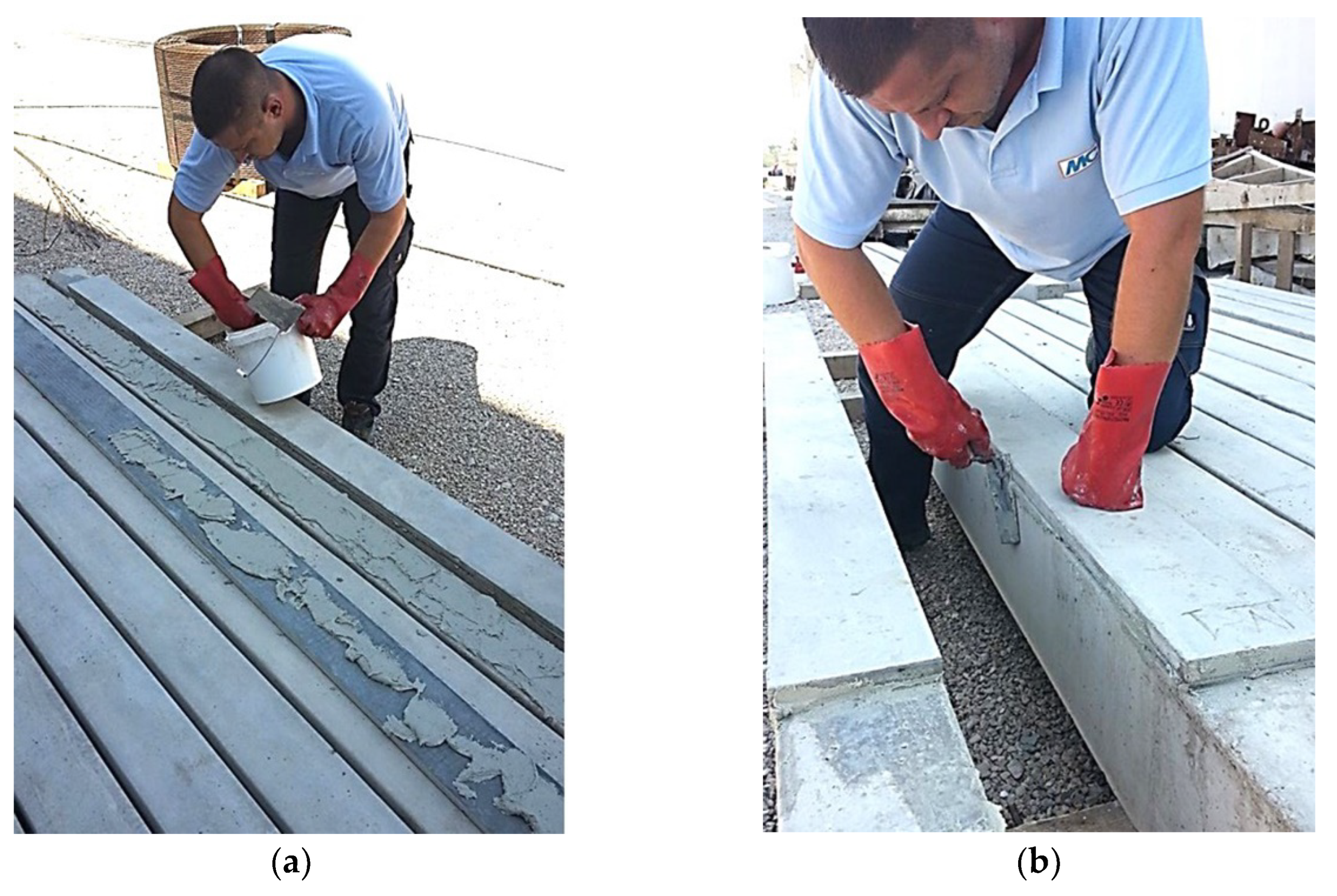
Figure 8.
RC beam loaded with two concentrated forces: (a) Schematic diagram; (b) Layout of one of the tested experimental models.
Figure 8.
RC beam loaded with two concentrated forces: (a) Schematic diagram; (b) Layout of one of the tested experimental models.
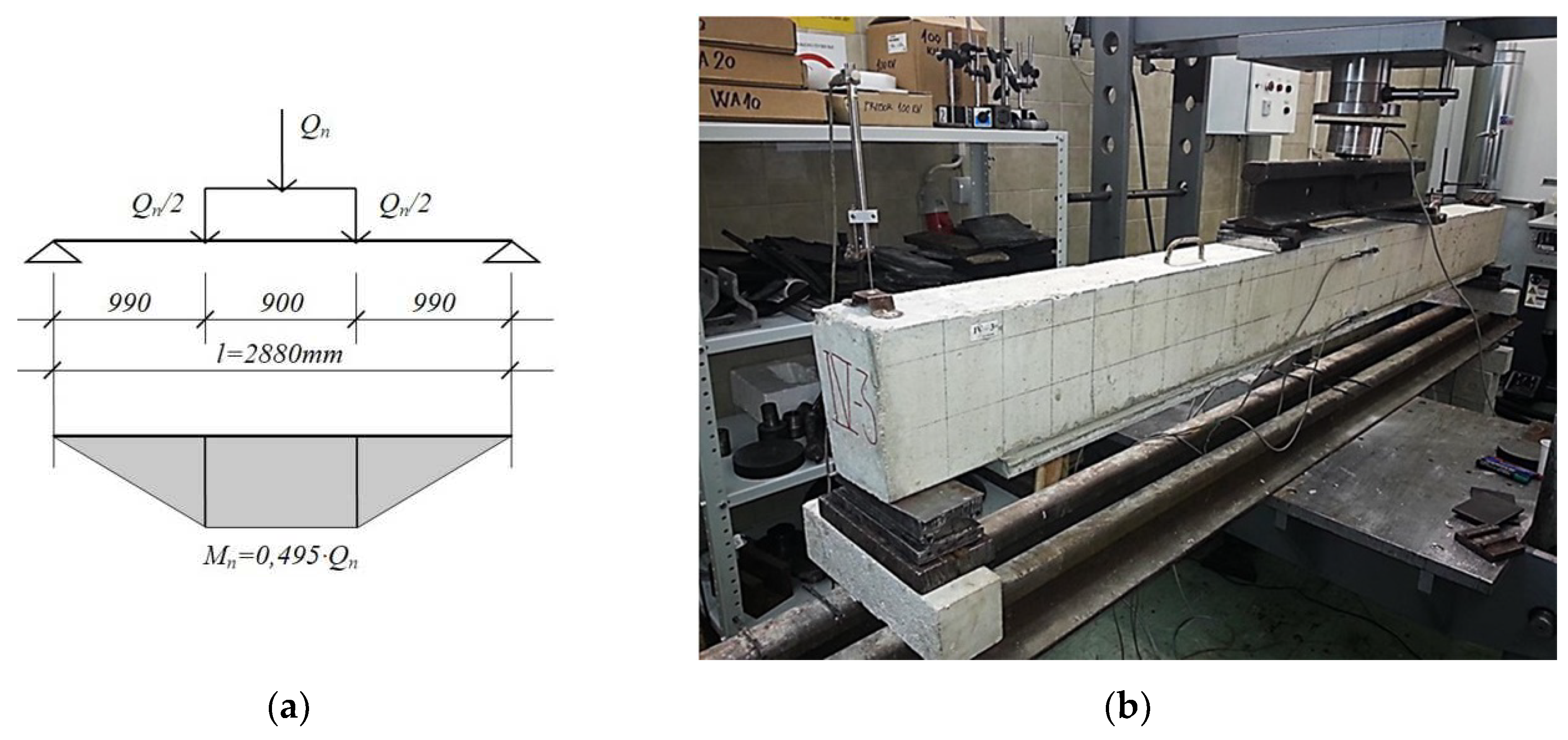
Figure 9.
Constitutive materials of strengthened experimental models.
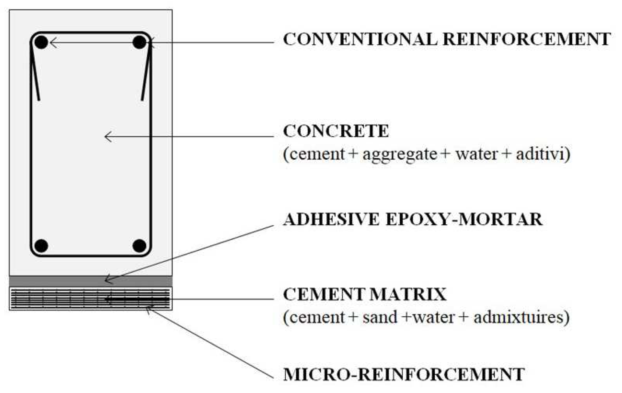
Figure 10.
Compressive uniaxial stress-strain curve for concrete [24].
Figure 10.
Compressive uniaxial stress-strain curve for concrete [24].
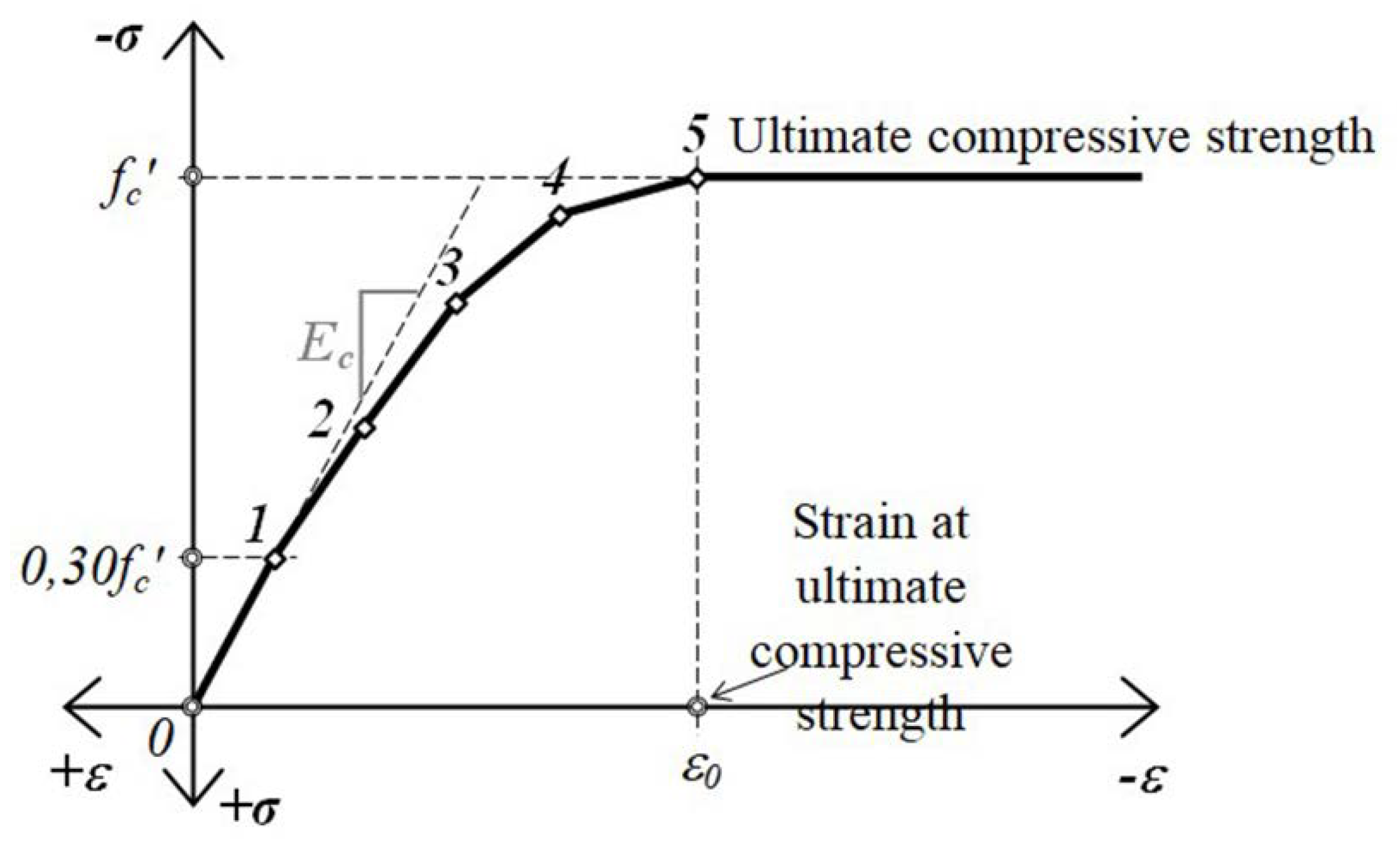
Figure 11.
RC beam numerical model: (a) Control (non-strengthened) RC beamc; (b) RC beams strengthened with ferrocement.
Figure 11.
RC beam numerical model: (a) Control (non-strengthened) RC beamc; (b) RC beams strengthened with ferrocement.
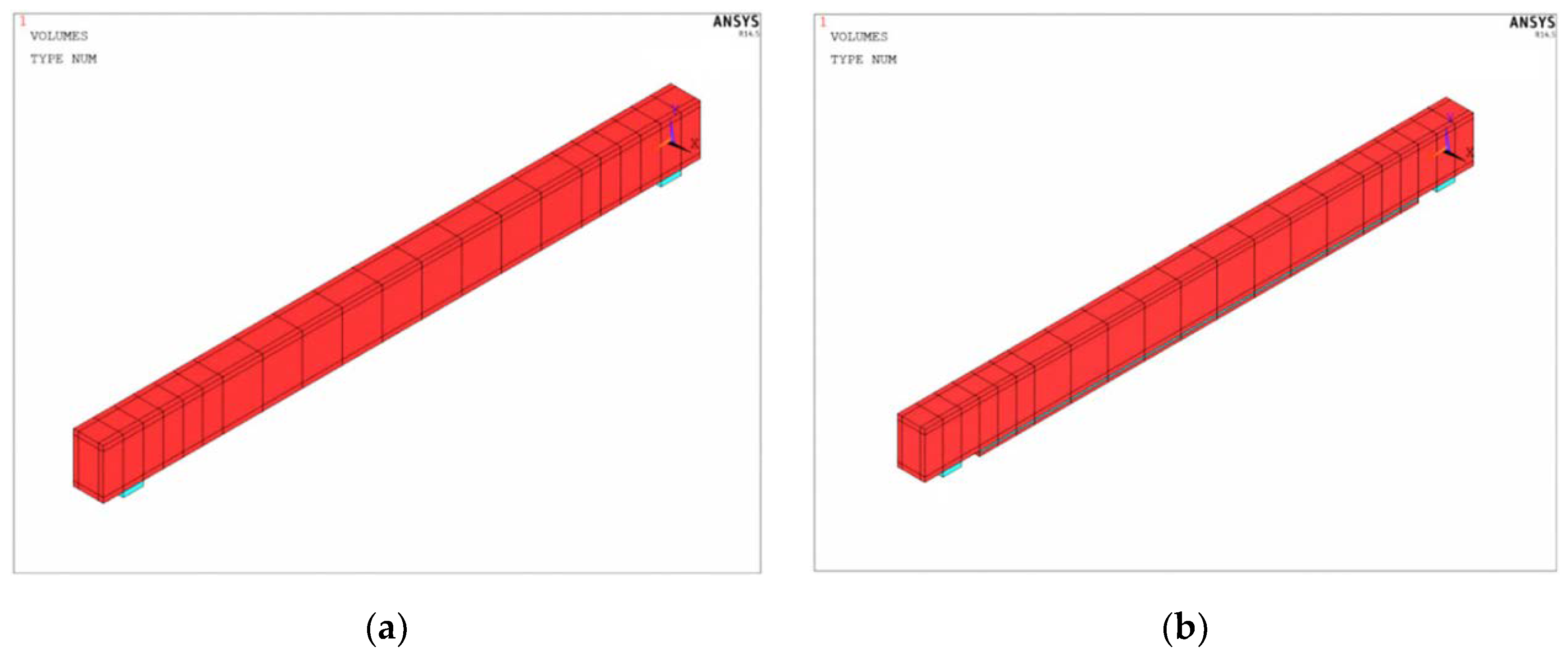
Figure 12.
Load bearing capacity failure of non-strengthened experimental models.
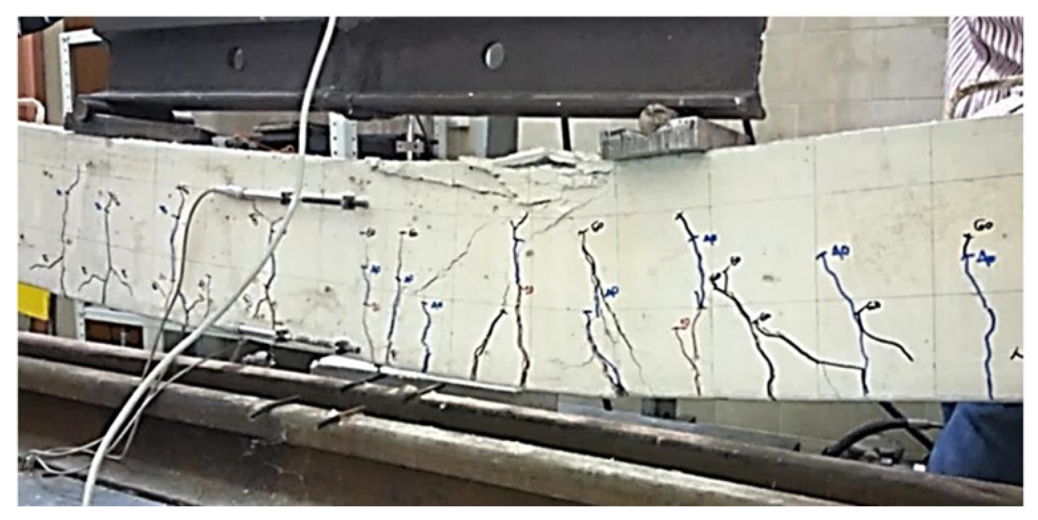
Figure 13.
Load bearing capacity failure of strengthened experimental models.
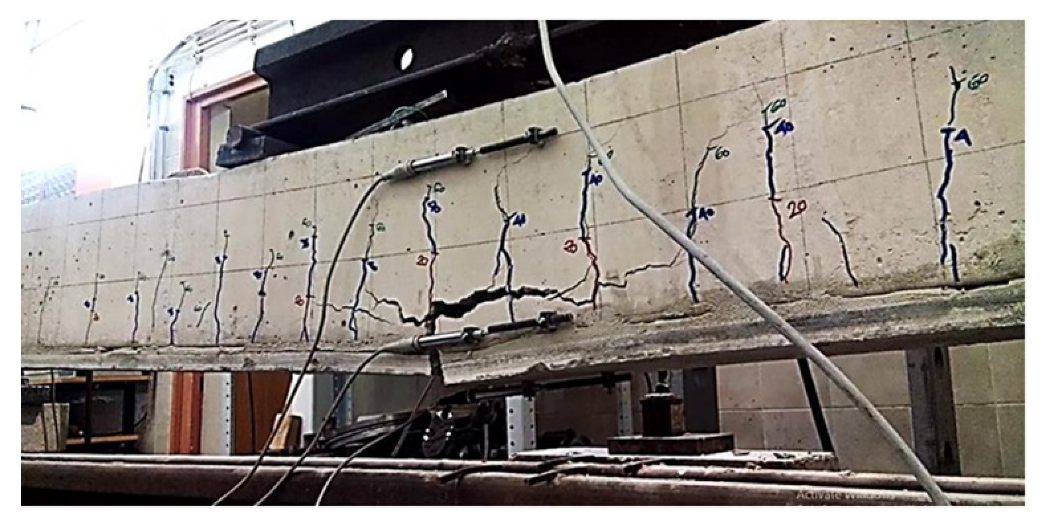
Figure 14.
Characteristic deflection diagrams, measured at middles of the spans of all types of models.
Figure 14.
Characteristic deflection diagrams, measured at middles of the spans of all types of models.
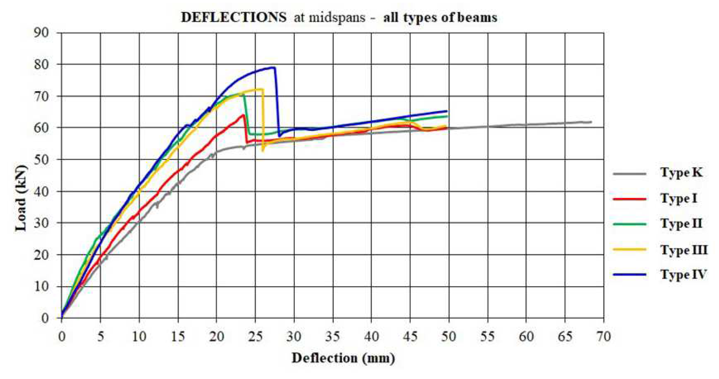
Figure 15.
Maximum deflections (mean value at the middle of spans) of types of models.
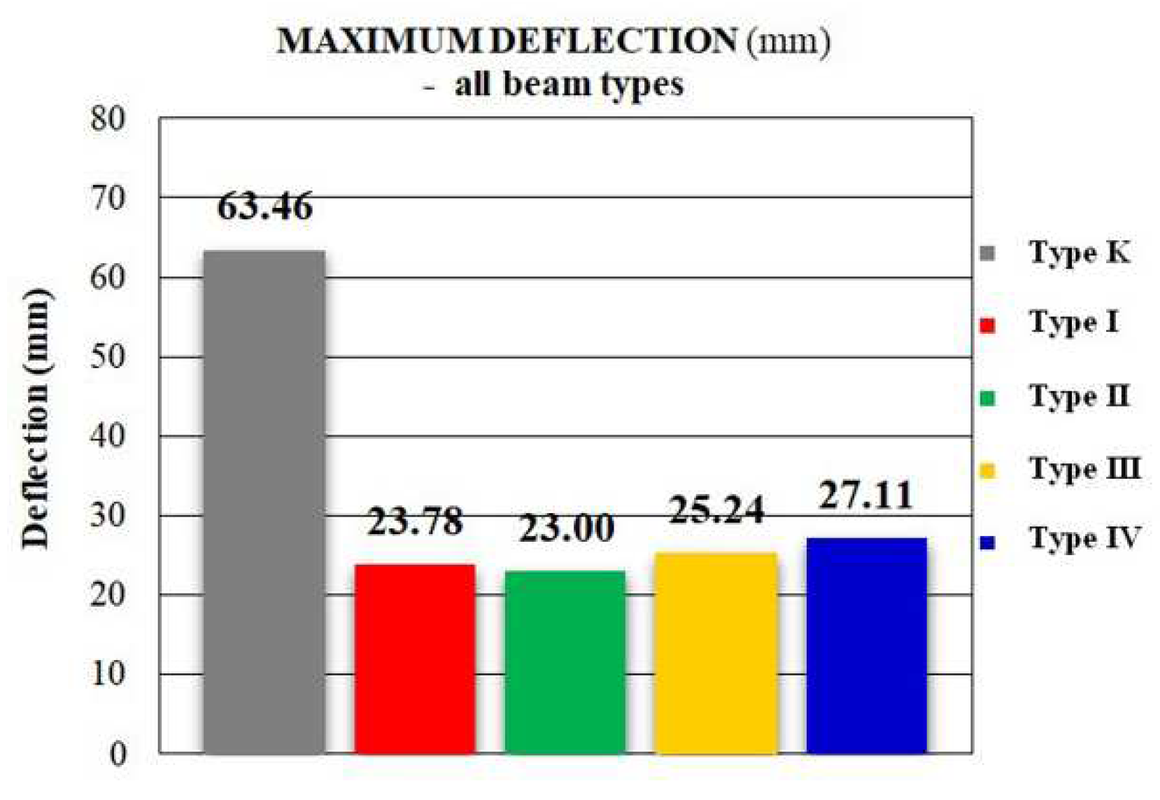
Figure 16.
Maximum load bearing capacity (mean failure force) of all types of models.
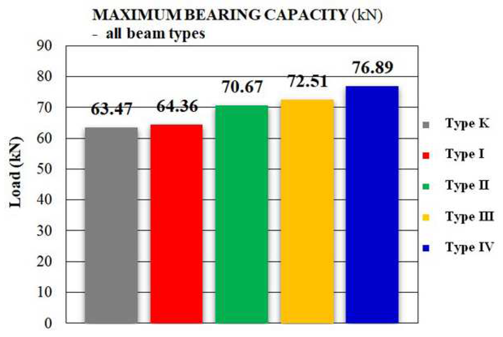
Figure 17.
Comparative deflection diagrams at middle spans of non-strengthened beam K type model.
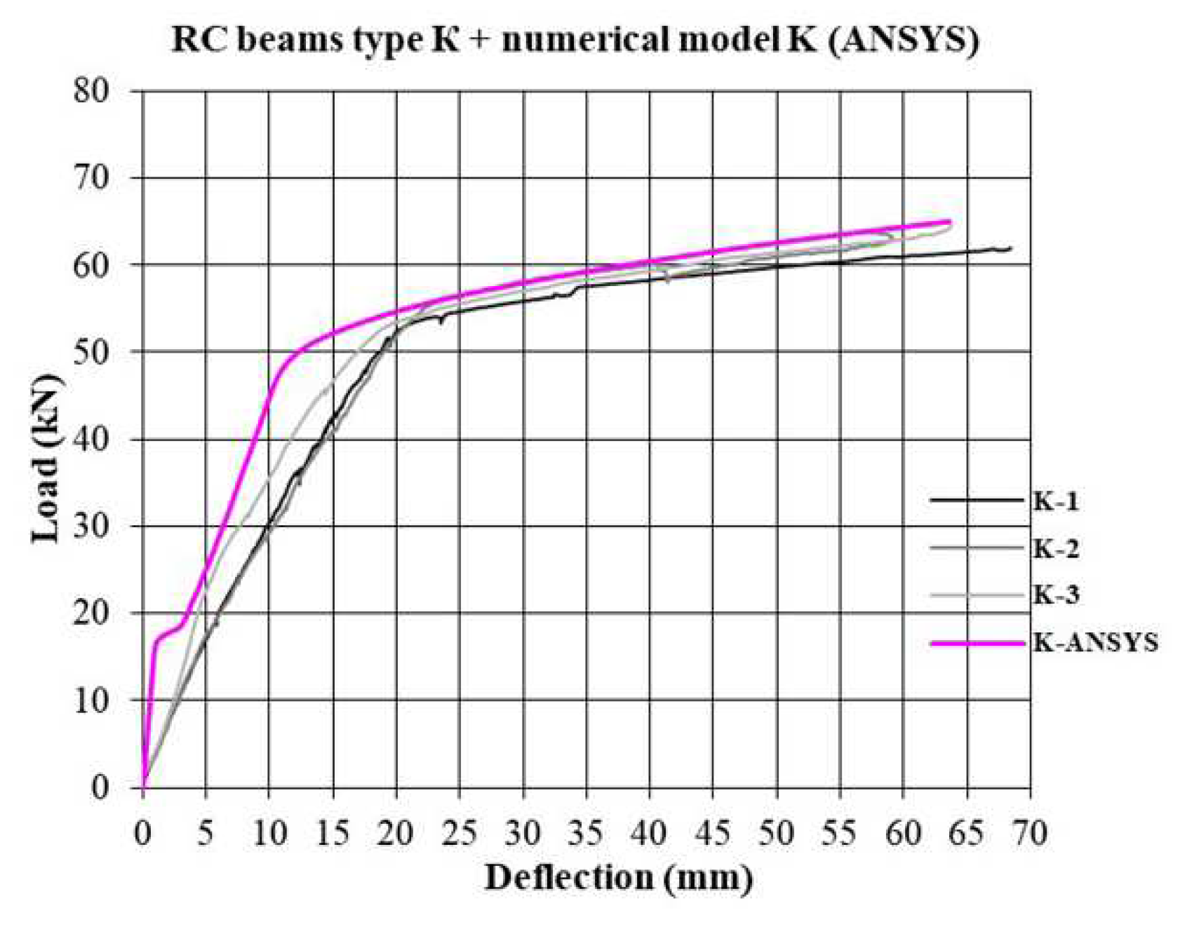
Figure 18.
Comparative deflection diagrams at middle spans of strengthened beam: (a) Type I beam model ; (b) Type II beam model.
Figure 18.
Comparative deflection diagrams at middle spans of strengthened beam: (a) Type I beam model ; (b) Type II beam model.
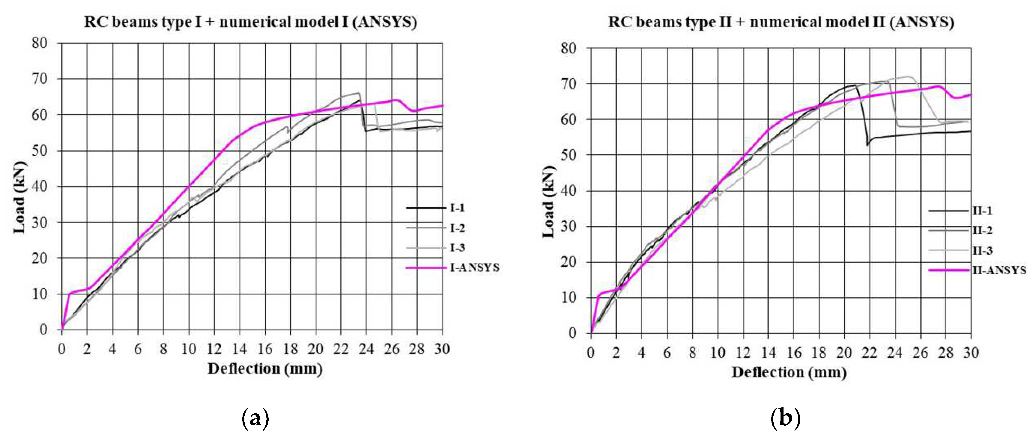
Figure 19.
Comparative deflection diagrams at middle spans of strengthened beam: (a) Type III beam model ; (b) Type IV beam model.
Figure 19.
Comparative deflection diagrams at middle spans of strengthened beam: (a) Type III beam model ; (b) Type IV beam model.
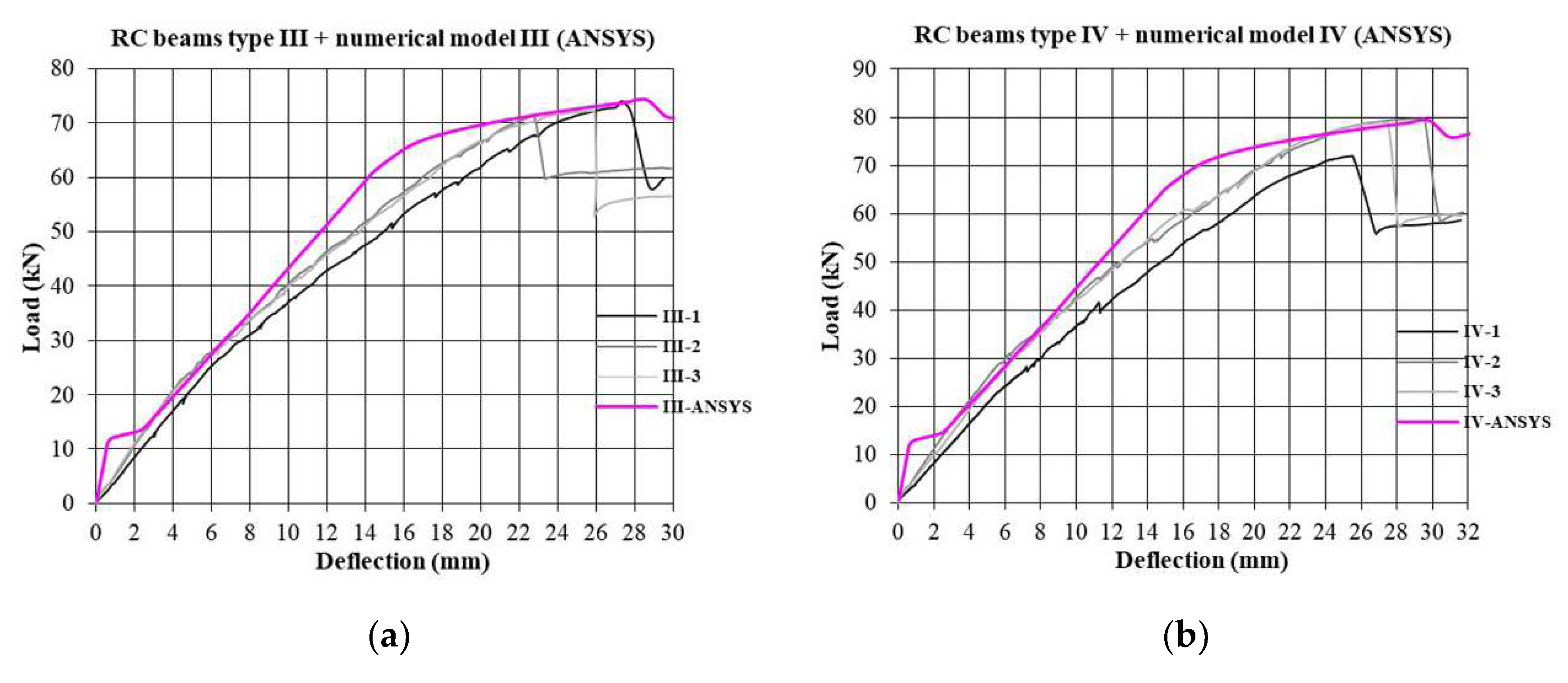

Table 1.
The thickness of ferrocement elements and number of micro-reinforcement layers.
| Type of ferrocement element (strip) | Thickness of ferrocement element (mm) | Number of micro-reinforcement layers |
|---|---|---|
| I | 17 | 8 |
| II III IV |
19 21 23 |
10 12 14 |
Table 2.
Mechanical properties of constitutive materials.
| Properties | Value |
|---|---|
| Compressive strength of concrete | fc,c=47,92MPa |
| Modulus of elasticity of concrete | Ec=28,05GPa |
| Yield strength of the reinforcement | fsy=580,30MPa |
| Ultimate tensile strength of the reinforcement | fsu=730,93MPa |
| Modulus of elasticity of reinforcement | Es=200,0GPa |
| Compressive strength of adhesive epoxy-mortar | fam,c=45,0MPa |
| Modulus of elasticity of adhesive epoxy-mortar | Eam=5,20GPa |
| Compressive strength of cement-based mortar | fm,c=43,0MPa |
| Modulus of elasticity of cement-based mortar | Em=20,0GPa |
| Yield strength of the micro-reinforcement (mesh) | fry=562,27MPa |
| Ultimate tensile strength of the micro-reinforcement (mesh) | fru=670,43MPa |
| Modulus of elasticity of micro-reinforcement (mesh) | Er=200,0GPa |
Table 3.
Calculation of characteristic points of compressive uniaxial stress-strain curve for concrete.
Table 3.
Calculation of characteristic points of compressive uniaxial stress-strain curve for concrete.
| Point | Value |
|---|---|
| 0 | Initial point (zero state of stress and strain) |
| 1 | Based on the Hooke’s law and expression the result is |
| 2, 3, 4 | Based on the expression with strain calculated from the expression |
| 5 | data Maximum compression stress at strain |
Table 4.
Adopted dimensions of finite elements of constitutive materials of beam models.
| Material of experimental beam models | Finite element type | Element dimensions (mm) |
|---|---|---|
| Concrete | SOLID 65 | 25×25×25 hexagonal |
| Conventional Steel reinforcement |
LINK 180 | l=25 linear |
| Ferrocement (cement-based matrix + steel micro-reinforcement) |
SOLID 65 | 25×25×17 (type I) 25×25×19 (type II) 25×25×21 (type III) 25×25×23 (type IV) hexagonal |
| Adhesive epoxy-mortar |
SOLID 185 | 25×25×10 hexagonal |
Table 5.
Maximum service bending moment (Mservice) (Transformed area method for the cracked section).
Table 5.
Maximum service bending moment (Mservice) (Transformed area method for the cracked section).
| RC beam type |
Mservice1 (kNm) |
Mservice2 (kNm) |
|---|---|---|
| I | 18,37 | 21,80 |
| II | 19,15 | 22,30 |
| III | 19,94 | 22,80 |
| IV | 20,75 | 23,29 |
| K | 15,40 | 19,77 |
1 when σs,max=0,6·fsy. 2 when σc,max=0,45·fc,c.
Table 6.
Ultimate (Mu) and nominal bending moment (Mn) (with partial safety coefficient γ=1,5).
| RC beam type |
Mservice1 | ||
|---|---|---|---|
| I | 18,37 | 27,56 | 30,62 |
| II | 19,15 | 28,73 | 31,92 |
| III | 19,94 | 29,91 | 33,23 |
| IV | 20,75 | 31,13 | 34,58 |
| K | 15,40 | 23,10 | 25,67 |
1 when σs,max=0,6·fsy, (Table 5).
Table 7.
Ultimate (Mu) and nominal bending moment (Mn) (with partial safety coefficient γ=1,7).
| RC beam type |
Mservice1 | ||
|---|---|---|---|
| I | 18,37 | 31,23 | 34,70 |
| II | 19,15 | 32,56 | 36,17 |
| III | 19,94 | 33,90 | 37,66 |
| IV | 20,75 | 35,28 | 39,19 |
| K | 15,40 | 26,18 | 29,09 |
1 when σs,max=0,6·fsy, (Table 5).
Table 8.
Comparison of nominal bending moments (Mn).
| RC beam type |
Transformed area method for the cracked section |
Transformed area method for the cracked section |
Compatibility method | Simplified method based on all tensile reinforcement yielding |
|---|---|---|---|---|
| I | 30,62 | 34,70 | 30,45 | 30,46 |
| II | 31,92 | 36,17 | 31,43 | 31,43 |
| III | 33,23 | 37,66 | 32,40 | 32,40 |
| IV | 34,58 | 39,19 | 33,38 | 33,38 |
| K | 25,67 | 29,09 | 26,65 | 26,63 |
Table 9.
Comparison of failure force (Qn) calculated analytically, mean failure force of experimental models and failure force of numerical models.
Table 9.
Comparison of failure force (Qn) calculated analytically, mean failure force of experimental models and failure force of numerical models.
| RC beam type |
Transformed area method for the cracked section |
Transformed area method for the cracked section |
Compatibility method | Simplified method based on all tensile reinforcement yielding | Mean failure force of experimental models | Failure force of numerical models |
|---|---|---|---|---|---|---|
| Figure 8(a) | Figure 8(a) | Figure 8(a) | Figure 8(a) | Figure 16 | Figures 17,18,19 | |
| I | 61,86 | 64,36 | 61,52 | 61,54 | 64,36 | 64,42 |
| II | 64,49 | 70,67 | 63,50 | 63,50 | 70,67 | 69,88 |
| III | 67,13 | 72,51 | 65,46 | 65,46 | 72,51 | 74,36 |
| IV | 69,86 | 76,89 | 67,43 | 67,43 | 76,89 | 79,92 |
| K | 51,85 | 63,47 | 53,84 | 53,80 | 63,47 | 65,21 |
Disclaimer/Publisher’s Note: The statements, opinions and data contained in all publications are solely those of the individual author(s) and contributor(s) and not of MDPI and/or the editor(s). MDPI and/or the editor(s) disclaim responsibility for any injury to people or property resulting from any ideas, methods, instructions or products referred to in the content. |
© 2023 by the authors. Licensee MDPI, Basel, Switzerland. This article is an open access article distributed under the terms and conditions of the Creative Commons Attribution (CC BY) license (http://creativecommons.org/licenses/by/4.0/).
Copyright: This open access article is published under a Creative Commons CC BY 4.0 license, which permit the free download, distribution, and reuse, provided that the author and preprint are cited in any reuse.


