
Submitted:
10 August 2023
Posted:
14 August 2023
You are already at the latest version
Abstract
Keywords: glycerin; Ni-based catalyst; lanthanum; semi-industrial scale; hydrogen production; biorefinery; monitoring.
Keywords:
glycerin
; Ni-based catalyst
; lanthanum
; semi-industrial scale
; hydrogen production
; biorefinery
; monitoring
1. Introduction
1.1. Biodiesel production
Global energy system will be dominated by fossil fuels, which currently represent around 85 % of total energy supply, whereas by 2030 it will represent 90 % of total supply. Oil will be the main energy source (34 %), followed by coal (28 %). Almost two thirds of the increase in coal supply between 2000 and 2030 will come from Asia. According to future trends, natural gas will imply a quarter of total energy supply in 2030, on account of an increase in electricity generation [1].
Another environmental problem is oil consumption due to vehicles, which imply considerable amounts of evolved gases taking part in greenhouse effect. Apart from these factors, continuous changes in oil prices, as well as its questionable future availability, have contributed to the development of vehicles working with electric power or whose fuel is methanol or ethanol, or other natural sources that can contribute to environmental protection, such as the use of vegetable oils to produce biodiesel, a perfect replacement for diesel in Diesel engines as it present many advantages such as biodegradability, higher lubrication efficiency and similar yields and efficiency in Diesel combustion engines, where it can be directly used if it complies with some quality standards [2].
In that sense, many vegetable oils, including safflower, rapeseed, cardoon or waste cooking oil, among others, have been successfully used for biodiesel production, with suitable properties according to UNE-EN 14214 standard [3] in most cases, except for its low oxidative stability, which can be easily improved by antioxidant addition such as tert-Butylhydroquinone (TBHQ), butylated hydroxy anisole (BHA) or propyl gallate (PG) [4,5,6,7,8,9]. Apart from that, genetically modified crops, with lower amounts of linoleic and linolenic acid (which cause a considerable decrease in oxidative stability) could be another interesting alternative to comply with the standard [10]. In any case, many studies have been carried out to optimize the effectiveness of biodiesel production and performance in Diesel engines to make this process as much competitive as possible, with the subsequent sustainable development [11,12,13,14]. Consequently, biodiesel production is going to play an important role in the short and long term, as observed in Figure 1 for global biodiesel production in million liters. This way, biodiesel production will triple in 15 years, pointing out the global concern about the replacement of petrol-based fuels for other sustainable alternatives. This could be due to the fact that many governments or international agencies (for instance, the so-called Sustainable Development Goals [15]) are encouraging the use of these kind of fuels in order to avoid environmental and sustainability problems.
As commented above, biodiesel present many advantages compared to conventional Diesel, such as higher biodegradability (as it comes from natural sources such as vegetable oils, and the chemical process produce similar molecular structures which are easily processed by microorganisms), zero-net CO2 emissions, high flash and combustion points, the possibility of a sustainable economic growth in developing areas (as many oilseed crops can be easily adapted to extreme climate conditions such as drought or heat), etc.
Biodiesel is mainly obtained from vegetable oils through transesterification with methanol, reacting triglycerides with this alcohol to obtain fatty acid methyl esters (FAMEs) and glycerol, as observed in Figure 2. This global reaction takes place in three consecutive and reversible stages where one mol of triglyceride is converted to diglyceride, monoglyceride and glycerol, respectively, obtaining one mol of fatty acid methyl ester in each reaction. The use of catalysts (both homogeneous and heterogeneous or acid and alkaline catalysts, which present their own advantages and challenges), for instance sodium methylate, is required in order to make the process more efficient [17,18,19,20].
Once fatty acid methyl esters (that is, biodiesel) are obtained, the purification process usually requires glycerol removal through decantation and washing treatments if homogeneous catalysts are used. Finally, a drying stage takes place, and the final product is obtained (normally biodiesel with at least 96.5 % FAME content).
1.2. Glycerol: Characteristics and prospective
Traditionally, glycerol was obtained through several processes such as soap making or fatty alcohol, fatty acid methyl ester and fatty acid production, through synthetic methods or other methods such as microbial fermentation [23,24]. A summary of the main properties of glycerol can be found in Table 1.
Thus, glycerol is not toxic nor irritant, soluble in water and alcohols and stable at low pressure values and room temperature.
Depending on the degree of purity of glycerol, it can be an interesting energy source (such as reforming or pyrolysis for energy) or the starting point for the synthesis of other products such as C3 compounds (such as acrolein, propanediols or carboxylic acids) obtained from routes such as hydrogenation, oxidation or esterification or activated carbons through pyrolysis [22,25,26]. Considering the future trend about biodiesel production, it is no surprising that glycerol generation has considerably increased in recent years, which can imply an opportunity for its reuse in industrial processes.
Thus, a feasible possibility is the use of glycerol as an energy source to obtain synthesis gas (a mixture of hydrogen and carbon monoxide at different ratios). This synthesis gas, if it is suitably treated, can produce fuel in an environmentally friendly process, as glycerol is obtained from chemical routes by using renewable raw materials [27].
1.3. Glycerol steam reforming
Glycerol steam reforming is one of the most typical methods to produce hydrogen in industry, as it is efficient and profitable at industrial level [22,28]. This technique does not require excessively high pressures and higher hydrogen percentages are produced at high temperatures. Steam reforming consists of conversion of hydrocarbons to hydrogen or synthesis gas, through a treatment at high temperatures with an oxidizing agent and a catalyst. Thus, glycerol reacts with steam to produce H2, CO2 and CO, in a highly endothermal process (ΔH0=123 kJ/mol) represented in Equation 1, which is a combination of glycerol decomposition (Equation 2) and Water Gas Shift reaction (WGS, Equation 3) [29]:
Consequently, H2 and CO ratio depends on reaction conditions, including the kind of catalyst used, as CO can be converted in WGS reaction to produce carbon dioxide. Also, other secondary reactions can take place, such as methane generation through exothermal reactions like those included in Equations 4 and 5:
As a consequence, the presence of these secondary reactions explains the difficulty to reach 100 % H2 production during glycerol steam reforming. To increase H2 production, through glycerol steam reforming, a suitable catalyst selection should be carried out to promote the cleavage of C-C, O-H and C-H bonds in the oxygenated hydrocarbon reactant and facilitate WGS to remove adsorbed CO [29]. Other factors with a strong influence on glycerol steam reforming are the following:
- Feed flow: overfeeding could reduce the yield of conversion, whereas the contrary could imply a poor gas production. The optimum flow maximizes the energy efficiency of the process.
- Temperature: This is one of the key factors, as it affects the yield of the process and gas composition. In general, high temperature values corresponds to higher gas production and higher H2 percentage in outlet gas.
- Steam to carbon (S/C) ratio: As it increases, the gas produced is richer in hydrogen, whereas gas flow decreases.
- Catalyst use: The use of catalysts (normally transition metals belonging to group VIIIB) is essential in this kind of process to obtain high conversion values. Also, the use of a support (such as Al2O3, ZrO2, SiO2 or TiO2) can promote conversion, and particle size can play an important role to favor mass transfer and contact among reagents within the reactor. Also, the use of additives or promoters can improve activity or service life by avoiding problems such as poisoning or carbon deposition [30,31].
Hydrogen production from renewable biomass has gained interest in recent years in scientific community, international agencies, and governments, promoting its implementation through international green chemistry policies [32]. Thus, biomass and glycerol reforming has been studied through gasification to improve glycerol conversion to hydrogen depending on temperature, pressure, and steam to carbon ratio, obtaining favorable results at high temperatures and low pressures. This study determined that the optimum condition to produce hydrogen was between 700 and 750 °C, at 0.1 MPa, concluding that glycerol and biomass steam reforming is feasible at practical operating temperatures, typical at industrial level [33].
Similar studies tested glycerol valorization obtained from biodiesel synthesis to obtain a gas rich in H2 through a sequential process where the first step consisted of glycerol purification to reduce impurities and, afterwards, it underwent steam reforming. The theoretical and experimental studies showed that temperature and glycerol concentration had a considerable influence on thermodynamics, with an optimum point at 700 °C and a carbon conversion to gas of around 95 %, with a gas composition of 67 % H2, 22 % CO2, 11 % CO and 1 % CH4 [34]. Equally, hydrogen production through ethanol and glycerol steam reforming was carried out with Ir, Co and Ni catalysts supported on CeO2, finding that the former (Ir/CeO2) provided a full conversion of glycerol at 400 °C, whereas total conversion for Co/CeO2 and Ni/CeO2 took place at 425 and 450 °C, respectively [35]. Another study pointed out the role of promoters such as Mg, Zr, Ce or La in Ni-Al2O3 catalysts, increasing hydrogen selectivity during the process and obtaining full conversion of glycerol at 600 °C (at atmospheric pressure) and a space velocity of 2.5 h-1. Ni, Ir and Co were effective for CeO2, with total conversion of glycerol and 90 % selectivity for hydrogen at 550 °C [36]. For additional purification of hydrogen, membrane reactors can be used in order to increase hydrogen percentage in the final gas, with Pd-Ag membranes being one of the most popular alternatives for this purpose [24].
Thus, glycerol turns out to be a good candidate to be a renewable source for hydrogen production. Its conversion to hydrogen (depending on the use of purification technologies such as membrane reactors or pressure swing adsorption [37,38]) or synthesis gas can be reached through reforming processes such as steam reforming (SO), partial oxidation or gasification (PO), autothermal reforming (ATR), aqueous phase reforming (APR) and steam reforming with supercritical water (SCW). These chemical routes depend on the properties of the catalyst used, generally Ni, Pt and Ru (which favors hydrogen production) as well as temperature, pressure, and reagent ratio. Hence, these factors should be considered when H2 yield is evaluated for each process[24].
1.4. Objective of this work
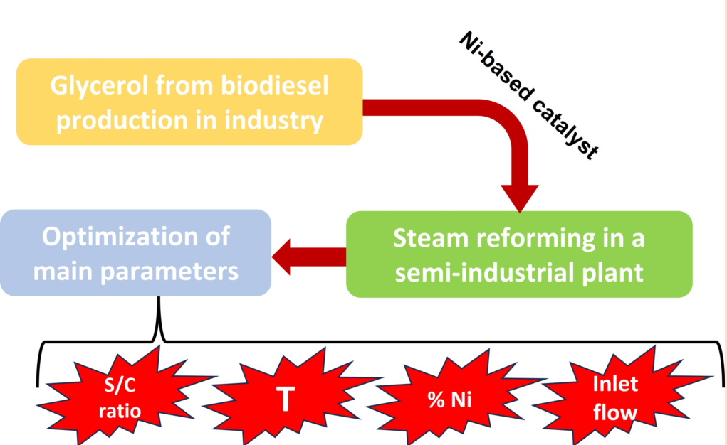
Considering the above, the aim of this work was to carry out the steam reforming of glycerol in an experimental facility at semi-industrial scale, trying to optimize this process in order to obtain suitable gasification powers regarding steam to glycerol ratio, paying attention to the feasibility of Ni-based catalyst applied to this facility. Specifically, the outlet gas flow was optimized, as well as hydrogen mole fraction and power. On the other hand, the selection of the chemical conditions to obtain the best catalytic performance was another specific objective, using for that purpose different NiO concentrations and comparing with non-catalytic tests. Finally, in light of these comparisons, our aim was to establish the optimum operating conditions of the semi-industrial plant according to gas flow, hydrogen mole ratio, lower calorific value and power.
2. Materials and Methods
2.1. Glycerol pre-treatment
Glycerol was obtained from a biodiesel plant (Green Fuel Extremadura), which approximately produces 110000 tons per year, with the subsequent generation of glycerol (around 1100 tons per year). Obviously, this glycerol is not pure and therefore some properties are different compared to pure glycerol, as it presents some impurities that might modify its behavior in different uses. Therefore, a characterization of crude glycerol was carried out, including proximate, ultimate analysis and high heating value determination. The main results are included in Table 2. As it can be inferred from this table, it was proved that glycerol presented some impurities that could interfere with a suitable performance of this product during steam reforming. For instance, S content could imply hydrogen sulfide generation during steam reforming, which could be a considerable problem for catalyst deactivation through poisoning. Consequently, to purify glycerol to remove impurities, it was heated at 120-130 °C for 120 hours, in order to reduce moisture and provoke precipitation of salts, which are filtered and removed.
Thus, the impurities of glycerol were considerably reduced, allowing its use in further treatments during steam reforming.
2.2. Catalyst preparation
Regarding the catalyst used (Ni/La-Al2O3 catalyst), it required different steps to be produced, like the following:
- γ-Al2O3 rings were calcined in an oven at 750 °C for 3 h.
- Afterwards, wet impregnation with a La(NO3)3∙6H2O solution was carried out in order to obtain 5 % La2O3. The impregnation took place at different steps (to avoid support saturation), followed by drying in a microwave oven (100 W for 15 min), to make sure that the support adsorbed the solution. Then, the impregnated support was calcined at 650 °C for 6 h, obtaining through weight difference 4.46 % of La2O3.
- The following step was the impregnation of the calcined support with Ni(NO3)2∙6H2O to obtain Ni as active phase in the final catalyst. Ni content was measured by NiO percentage. Ni concentration was varied, adding the corresponding amount of its nitrate to obtain different NiO percentages (12, 16 and 20 % w/w). Equally, three stages of impregnation took place, with the corresponding drying in microwave oven as in the previous case. The main impregnation steps taking place are included in Figure 3. Finally, after calcination at 500 °C for 4 h once the nitrate was impregnated, the final catalyst was obtained. Once calcined, NiO content was calculated through weight difference, obtaining the corresponding values depending on each experience.
- Finally, catalyst reduction at 700 °C for 2 h (at a heating rate of 10 °C/min) in 50 % H2/N2 atmosphere was carried out, obtaining the final catalyst.
As a result, catalyst characterization was similar to previous studies with the same catalysts [39].
2.3. Experimental setup
Regarding our experimental facility, Figure 4 shows a general outline of the glycerol steam reforming system and its main components.
Some of the main components of this glycerol steam reforming system will be briefly explained, included in Figure 5. Thus, the aim of the drying system (Figure 5a), a steel tank of 35 L, was to dehydrate wet glycerol. The heating jackets (2 units) were used to cover the drying system and heat it at 120-130 °C to remove salts in glycerol (Figure 5b). The glycerol-water mixture steel tank (Figure 5c) had a capacity of 30 L, with the aim of mix purified glycerol with distilled water (at a specific ratio) to obtain one single homogeneous phase before introducing it in the reactor. The stirrer was designed to mixture highly viscous substances, through a stainless-steel anchor.
On the other hand, the distiller (Figure 5d) obtains distilled water from tap water. The peristaltic pump (Figure 5 e) provides the glycerol-water mix to the reactor, at a constant and controlled flow rate. The aim of the basket (Figure 5f) is to provoke the contact of gas and heated areas to assure a correct gasification and to retain the carbon residue produced during this process. The reactor (a stainless-steel cylinder, see Fig 5g) is the element where glycerol steam reforming is going to take place, which is covered by an electric oven (Figure 5h) covering the central part of the reactor to obtain around 700-800 °C within the reactor. Temperature is controlled by a PID controller, measuring inner temperature through a thermocouple.
Finally, once the outlet gas is produced in the reactor, they are cooled down through a heat exchanger (Figure 5i) connected to a chiller, obtaining condensate liquids in the corresponding tank. Gas flow was measured by a float-type flow meter (Figure 5j), and dataloggers are used to measure temperature at different points of the system. The outlet gas composition (mainly H2, CO, CO2, CH4) was determined through gas chromatography, using a Varian 3900 chromatograph (Figure 5k) coupled to a thermal conductivity detector, with a packed column (Supelco Carboxen 1000 60/80). The carrier gas was argon and synthetic air.
In this study, the introduction of certain improvements in the steam reforming system, compared to previous studies, was carried out. The main upgrades are included in Table 3:
2.4. Experiments conducted
In order to carry out the experiments, the catalyst (with the suitable Ni and La proportion for each experiment) was added to the basket, closing it perfectly and preparing the corresponding glycerol-distilled water blend, controlling the flow rate to be introduced through the peristaltic pump, previously calibrated. Once the catalyst was activated through a N2/H2 flow, the carrier gas was changed to 100 % N2 for 30 minutes.
Then, the oven is set to the corresponding reaction temperature, and once it was reached, the glycerol-water blend was introduced, which was the starting point of glycerol steam reforming.
Afterwards, different gas samples were taken through Tedlar gas sampling bags to carry out the corresponding gas chromatography, measuring the gas flow once each sample was taken.
This way, according to previous experiences, fixed conditions were established for these experiments, such as water/glycerol ratio (W/G) and flow rate, which were previously optimized. Thus, temperature (in oven) will be varied in these experiments. For non-catalytic studies (with no active catalyst added to Al2O3 support), the conditions included in Table 4 were followed, whereas in the case of catalytic studies both temperature and catalyst proportion (NiO percentage, whereas La2O3 percentage was fixed at 5 %) were studied (see Table 4).
Thus, for these experiments, the stabilization time of glycerol steam reforming was determined according to outlet gas flow and gas composition, to assess the feasibility of this catalyst for its use in an industrial plant and which proportion provided the best results according to yield and gas quality.
Finally, the service life of the catalysts was determined, carrying out a final test to the catalyst with the best yield and measuring gas composition until its composition starts to decrease.
3. Results and Discussion
3.1. Stabilization test
Firstly, it is important to point out that, before gas sampling, it is necessary to check the stabilization of glycerol steam reforming under these conditions. This test was carried out at the lowest temperature contemplated in this work, whereas sampling will be similar to the criterion obtained from this experiment, as stabilization time depends on temperature (an increase in this parameter implies a decrease in stabilization). The experiment took place for 2 hours, and gas samples were taken every 15 minutes. The results are included in Figure 6.
As observed, time 0 was the beginning of the reaction once the oven reached 750 °C. Glycerol steam reforming tended to stabilize between 45 and 60 minutes, as CO, H2, C2H4 and CO2 percentages (whose values drastically varied at an initial stage) started to be stable over time. Regarding non-catalytic tests, gas sampling will be carried out once stabilization time was reached in this experience, that is, after 60 minutes of reaction time.
3.2. Non-catalytic Glycerol steam reforming at different temperatures
Concerning glycerol steam reforming without catalyst addition, Figure 7 shows the main results obtained for this experiment at different temperatures, including gas flow and hydrogen composition in outlet gas.
As observed in Figure 7a, there was a considerable increase in gas flow generated with temperature, from 16.04 to 30.93 L/min at 750 and 950 °C, respectively. Comparing with previous experiences at the same chemical conditions, the results obtained in this work at 950 °C were higher, proving that the improvements introduced in the glycerol steam reforming system were effective. Concerning hydrogen production (Figure 7b), its percentage increased with temperature at the same water/glycerol ratio and feed flow, obtaining slightly higher values compared to previous studies at 950 °C. This could be due to the fact that alumina without catalyst addition allowed the chemical modification and enrichment in hydrogen. Previous studies did not include any support addition, which provoked continuous load loss. These hydrogen percentages are in accordance with the literature, where yields ranging from 37 to 99.7 % were observed depending on the catalyst used [27].
Regarding low heating value (LHV) and power, Figure 8 shows the main results obtained. Thus, it can be concluded that, at the same steam/glycerol ratio and inlet flow, higher heating values were obtained at lower temperatures (15771.57 kJ/m3N at 750 °C), which can be due to the higher CO and hydrocarbon percentage under these conditions, whereas an increase in temperature provoked the chemical conversion of hydrocarbons to hydrogen (as observed in Figure 7b) and CO2, with the latter not contributing to LHV calculation and therefore decreasing its value.
On the other hand, power increased with temperature (from 4216.28 W at 750 °C to 6324.73 W at °C) due to its relationship with outlet gas flow according to Equation 6:
where Qoutlet gas is the flow of outlet gas and LHV is low heating value. Therefore, the influence of flow gas, which considerably increased with temperature as observed in Figure 7a, is higher compared to LHV (which showed an opposite trend with temperature). Again, previous studies, where the process was not optimized, offered lower power values compared to the present work, with 4.43 % decrease.
This way, it can be concluded that the improvements included in this work implied a better performance when it comes to glycerol steam reforming, as better outlet gas flow, hydrogen percentage and power values were found compared to equivalent previous studies.
3.3. Catalytic Glycerol steam reforming at different temperatures and catalyst concentrations
In the case of catalytic studies, Table 5 shows the main parameters selected for each experiment, fixing W/G ratio and inlet flow for all cases and varying temperature (from 750 to 850 °C) and catalyst concentration (from 12 to 20 % NiO).
For these tests, nitrogen was used as carrier gas in order to avoid air contact with the catalysts, implying the oxidation and, therefore, deactivation of the active phase. As in the case of non-catalytic experiences, a stabilization test was carried out, with gas sampling at every 15 minutes, to determine gas composition and to establish the time at which outlet gas presented constant composition. This experiment was carried out at the most unfavorable conditions, that is, at 750 °C.
As a result, Figure 9 shows the results at different catalyst concentrations (12, 16 and 20 % NiO). As it can be observed, in the case of 12 % NiO (Figure 9a), the reaction time required to stabilize outlet gas composition was about 70 minutes (considering the starting point when the carrier gas was disconnected, and the oven reached 750 °C). In the case of 16 % NiO (see Figure 9b), some fluctuations were observed, establishing an stabilization time at around 90 minutes, whereas regarding 20 % NiO (Figure 9c), the outlet gas composition was practically constant from 70 minutes, which will be the common sampling time for further analysis.
When outlet gas flow and its hydrogen composition were compared at different temperatures and catalyst concentrations, Figure 10 shows the main results, with a considerable improvement in gas flow and hydrogen yield when temperature was increased (see Figure 10a), as observed in other studies [40]. However, an increase in catalyst addition was not effective, obtaining better results with 12 % NiO concentration (34.88 kW at 850 °C) compared to 20 % NiO (26.55 kW at 850 °C). This fact could be due to a saturation effect when alumina rings were impregnated, provoking an undesirable active phase distribution on support surface. The same effect could have a similar influence on hydrogen percentage (see Figure 10b, with the best results observed for the lowest NiO concentration (41.35 % for 12 % NiO at 850 °C, whereas for 20 % NiO 34.42 % of hydrogen was obtained). As in the case of non-catalytic tests, there was an increase in hydrogen purity when temperature was increased.
Comparing power generation and LHV, according to Figure 11, the test with the highest catalyst content and temperature had the highest LHV (15.97 kJ/m3N), due to the lower H2 content but a higher percentage of hydrocarbons (C2H4 and C2H6) and CO, which have a strong influence on LHV. Nevertheless, tests carried out with 12 % NiO and 850 °C offered acceptable results regarding LHV (14.84 kJ/m3N), and gas composition was kept constant and at higher percentages compared to NiO 16 %, whose composition is richer in CO2, a compound that does not have an influence on LHV. Consequently, NiO 12 % had the highest power generation, observing a strong influence of outlet gas flow on this parameter. Thus, this catalyst proportion and temperature were selected for further experiences and analysis (considering optimum reaction conditions the following: W/G = 0.7; inlet flow = 40 ml/min; oven temperature = 850 °C; NiO concentration = 12 %). It should be noted that similar studies with Ni/CaO-Al2O3 at different Ni loadings (from 2.5 to 20 % wt) offered an optimum Ni loading of 15 %, with a high glycerol conversion (99.4 % at 700 °C) [41].
3.4. Lifetime determination of final catalyts under optimum conditions
One of the main problems related to the use of catalysts in steam reforming is the possibility of deactivation during the reaction due to different factors, such as poisoning caused by impurities such as hydrogen sulfide, coke deposition due to hydrocarbon decomposition or sintering of the active phase on account of high temperatures. These problems provoke the decrease in active sites or active area on catalyst surface, implying the continuous efficiency loss of the catalyst.
Thus, the use of promoters (such as Ce, Zr or La, in this case, which improved catalyst basicity, metal-support interaction and Ni dispersion, as it was proved in similar studies [42]) or mild reaction conditions could lengthen the useful life of catalysts [31,43,44].
Thus, in order to determine the lifetime of the selected catalyst (12 % NiO and 5 % La2O3), an experiment including the selected reaction conditions according to previous sections (that is, W/G = 0.7; inlet flow = 40 ml/min; oven temperature = 850 °C) was carried out, monitoring gas composition every 30 minutes for at least 10 hours. As a result, as observed in Figure 12, there was a slight change in H2, CO and CO2 composition at around 580 minutes, possibly due to the lower influence of WGS reaction (mainly responsible for changes in syngas composition). At this moment, it is possible that the catalyst did not promote this secondary reaction. On the other hand, the remaining gases (CH4, C2H4 and C2H6) come from the thermal decomposition of glycerol, and that is the reason why their mole fraction is not altered at this point.
Consequently, and even though the activity of the catalyst seems to be considerable after 700 min (especially concerning glycerol thermal decomposition), it should be noted that the changes in gas composition observed from 600 min should be taken into account, especially concerning further syngas processes or purification techniques where gas composition plays a vital role when it comes to industrial design. In previous studies, where Ni-La/Al2O3 was produced and characterized, the catalyst obtained (16 % NiO and 5 % La2O3) offered a high stability, with a minimum reusability of 5 times [39]. Similar catalysts (15 % Ni-CaO/Al2O3) studied in the literature showed a decline in catalytic conversion after 15 hours at lower temperatures (700 °C) [41]. Also, other works covered the catalytic activity of Ni-La-Ti mixed oxide catalysts for glycerol steam reforming, observing that there was a slight and continuous decrease in activity, possibly due to coke deposition on the catalyst [45]. Other studies pointed out the long stability of hydrogen selectivity (up to 12 h) of the catalyst used for glycerol steam reforming (Ni/CeZrO) at 500 and 600 °C [46].
3.5. Comparison between non-catalytic and catalytic steam reforming
Finally, this final experiment was compared with a non-catalytic steam reforming under the same chemical conditions except for temperature, which was increased by 100 °C in the case of the non-catalytic experiment. The main results about this comparison are included in Table 6:
As observed, and even though both experiments were carried out at different temperatures, there was a considerable increase in outlet gas flow when the catalyst was used, which points out the effectiveness of Ni catalyst to carry out glycerol steam reforming, allowing the use of lower temperatures for this purpose. Thus, Ni was effective due to its properties, promoting the reaction between water molecules and carbon bounds in water/glycerol mixture, producing higher and constant amounts of gas.
Regarding hydrogen production, a considerable percentage of this gas (exceeding 40 %) is found in the catalytic experiment, which proves the effectiveness of NiO to promote hydrogen production in the outlet gas. However, when non catalytic experiences at 950 °C were considered, gas composition was equivalent to the catalytic experiment, as high temperatures promote hydrogen production and therefore its proportion in final gas outlet. In any case, catalyst addition allowed the reduction in temperature reaction, with the subsequent saving on energy cost.
Finally, power and LHV were compared, observing 36 % and 21 % increase in power generation and LHV, respectively, when the catalyst was used at lower temperatures. Regarding LHV, this considerable increase in the case of the catalytic study was possibly due to the use of low temperatures, which implied lower CO2 amounts in outlet gas and higher hydrocarbon and CO proportions (which are elements with a strong influence on LHV). Concerning power generation, as outlet gas flow and LHV were higher by using NiO 12 % as a catalyst, it is no wonder that power, obtained by using Equation 6, was much higher compared to non-catalytic experiences.
4. Conclusions
The main findings of this work were the following:
- The catalyst that was most suitable for glycerol steam reforming was 12 % Ni, due to the fact that, during the impregnation process, the support adsorbed the supplied solution properly, whereas in the rest of cases it was not possible and the support tended to saturate.
- A considerable advantage is achieved when catalysts are used, compared to non-catalytic steam reforming, not reaching very high reaction temperatures.
- Due to the improvements introduced in the reactor, pressure drop considerably decreased, and therefore, the catalytic support was long enough in contact with the gas.
- After several hours of continuous operation in the glycerol steam reforming plant, the results might be altered due to coke deposition and condensate that can be generated.
- For an optimal production in the plant, it should not be operating for more than 9 hours, as this is the estimated useful life of the catalyst.
- The main disadvantage when it comes to catalyst implementation in this facility was coke deposition in the basket, which can promote catalyst deactivation.
- For a correct operation with catalysts, some steps should be carried out for re-using it, such as oven cleaning, activation processes, place it in the oven, etc.
- Finally, the main differences between optimal catalytic tests and non-catalytic ones make necessary the use of catalyst as long as the process takes place for less than 9 hours at a temperature of 850 °C.
Author Contributions
Conceptualization, J.F.G. and A.A.M.; methodology, A.A.M.; formal analysis, A.A.M. and A.G.A.; investigation, A.A.M., A.G.A. and S.N.; resources, J.F.G.; data curation, A.A.M. and S.N.; writing—original draft preparation, A.A.M., A.G.A. and S.N.; writing—review and editing, S.N.; visualization, J.F.G., A.A.M. and S.N.; supervision, J.F.G.; project administration, J.F.G. and A.A.M.; funding acquisition, J.F. All authors have read and agreed to the published version of the manuscript.
Funding
This research received no external funding.
Acknowledgments
The authors would like to thank Green Fuel Extremadura for the glycerol provided.
Conflicts of Interest
The authors declare no conflict of interest. The funders had no role in the design of the study; in the collection, analyses, or interpretation of data; in the writing of the manuscript; or in the decision to publish the results.
References
- Agencia Insular de Energía de Tenerife Perspectivas de La Evolución Mundial Hasta 2030 En Los Ámbitos de La Energía, La Tecnología y La Política Climática.
- Hasan, M.M.; Rahman, M.M. Performance and Emission Characteristics of Biodiesel–Diesel Blend and Environmental and Economic Impacts of Biodiesel Production: A Review. Renewable and Sustainable Energy Reviews 2017. [Google Scholar] [CrossRef]
- UNE-EN 14214:2013 V2+A1:2018 Liquid Petroleum Products—Fatty Acid Methyl Esters (FAME) for Use in Diesel Engines and Heating Applications—Requirements and Test Methods. 2018.
- Nogales-Delgado, S.; Encinar, J.M.; González, J.F. Safflower Biodiesel: Improvement of Its Oxidative Stability by Using BHA and TBHQ. Energies (Basel) 2019, 12. [Google Scholar] [CrossRef]
- Nogales-Delgado, S.; Guiberteau, A.; Encinar, J.M. Effect of Tert-Butylhydroquinone on Biodiesel Properties during Extreme Oxidation Conditions. Fuel 2022, 310, 122339. [Google Scholar] [CrossRef]
- Nogales-Delgado, S.; Encinar, J.M.; Guiberteau, A.; Márquez, S. The Effect of Antioxidants on Corn and Sunflower Biodiesel Properties under Extreme Oxidation Conditions. JAOCS, Journal of the American Oil Chemists’ Society 2019. [Google Scholar] [CrossRef]
- Nogales-Delgado, S.; Sánchez, N.; Encinar, J.M. Valorization of Cynara Cardunculus L. Oil as the Basis of a Biorefinery for Biodiesel and Biolubricant Production. Energies (Basel) 2020, 13. [Google Scholar] [CrossRef]
- Encinar, J.M.; Nogales, S.; González, J.F. Biodiesel and Biolubricant Production from Different Vegetable Oils through Transesterification. Engineering Reports 2020, 1–10. [Google Scholar] [CrossRef]
- Encinar, J.M.; Nogales, S.; González, J.F. The Effect of BHA on Oxidative Stability of Biodiesel from Different Sources. Greenhouse Gases: Science and Technology 2020, 10, 1193–1201. [Google Scholar] [CrossRef]
- Nogales-Delgado, S.; Encinar, J.M.; González Cortés, Á. High Oleic Safflower Oil as a Feedstock for Stable Biodiesel and Biolubricant Production. Ind Crops Prod 2021, 170, 113701. [Google Scholar] [CrossRef]
- Hanif, M.A.; Nisar, S.; Akhtar, M.N.; Nisar, N.; Rashid, N. Optimized Production and Advanced Assessment of Biodiesel: A Review. Int J Energy Res 2018, 42, 2070–2083. [Google Scholar] [CrossRef]
- Ajala, O.E.; Aberuagba, F.; Odetoye, T.E.; Ajala, A.M. Biodiesel: Sustainable Energy Replacement to Petroleum-Based Diesel Fuel—A Review. ChemBioEng Reviews 2015, 2, 145–156. [Google Scholar] [CrossRef]
- Sundus, F.; Fazal, M.A.; Masjuki, H.H. Tribology with Biodiesel: A Study on Enhancing Biodiesel Stability and Its Fuel Properties. Renewable and Sustainable Energy Reviews 2017. [CrossRef]
- Ramalingam, S.; Rajendran, S.; Ganesan, P.; Govindasamy, M. Effect of Operating Parameters and Antioxidant Additives with Biodiesels to Improve the Performance and Reducing the Emissions in a Compression Ignition Engine—A Review. Renewable and Sustainable Energy Reviews 2018. [CrossRef]
- UN Sustainable Development Goals. 2019.
- IEA Forecast Summary—Biofuel Use Expands in 2022 despite Rising Costs.
- Jayakumar, M.; Karmegam, N.; Gundupalli, M.P.; Bizuneh Gebeyehu, K.; Tessema Asfaw, B.; Chang, S.W.; Ravindran, B.; Kumar Awasthi, M. Heterogeneous Base Catalysts: Synthesis and Application for Biodiesel Production—A Review. Bioresour Technol 2021, 331, 125054. [Google Scholar] [CrossRef] [PubMed]
- Atadashi, I.M.; Aroua, M.K.; Abdul Aziz, A.R.; Sulaiman, N.M.N. The Effects of Catalysts in Biodiesel Production: A Review. Journal of Industrial and Engineering Chemistry 2013. [CrossRef]
- Tubino, M.; Junior, J.G.R.; Bauerfeldt, G.F. Biodiesel Synthesis with Alkaline Catalysts: A New Refractometric Monitoring and Kinetic Study. Fuel 2014, 125, 164–172. [Google Scholar] [CrossRef]
- Mazaheri, H.; Ong, H.C.; Amini, Z.; Masjuki, H.H.; Mofijur, M.; Su, C.H.; Badruddin, I.A.; Yunus Khan, T.M. An Overview of Biodiesel Production via Calcium Oxide Based Catalysts: Current State and Perspective. Energies (Basel) 2021, 14, 1–23. [Google Scholar] [CrossRef]
- Rodrigues, A.; Bordado, J.C.; Dos Santos, R.G. Upgrading the Glycerol from Biodiesel Production as a Source of Energy Carriers and Chemicals—A Technological Review for Three Chemical Pathways. Energies (Basel) 2017, 10. [Google Scholar] [CrossRef]
- Checa, M.; Nogales-Delgado, S.; Montes, V.; Encinar, J.M. Recent Advances in Glycerol Catalytic Valorization: A Review. Catalysts 2020, 10, 1–41. [Google Scholar] [CrossRef]
- Encinar, J.M.; Pardal, A.; Sánchez, N. An Improvement to the Transesterification Process by the Use of Co-Solvents to Produce Biodiesel. Fuel 2016. [Google Scholar] [CrossRef]
- Bagnato, G.; Iulianelli, A.; Sanna, A.; Basile, A. Glycerol Production and Transformation: A Critical Review with Particular Emphasis on Glycerol Reforming Reaction for Producing Hydrogen in Conventional and Membrane Reactors. Membranes (Basel) 2017, 7. [Google Scholar] [CrossRef]
- Hu, Y.; He, Q.; Xu, C. Catalytic Conversion of Glycerol into Hydrogen and Value-Added Chemicals: Recent Research Advances. Catalysts 2021, 11. [Google Scholar] [CrossRef]
- Raza, M.; Inayat, A.; Abu-Jdayil, B. Crude Glycerol as a Potential Feedstock for Future Energy via Thermochemical Conversion Processes: A Review. Sustainability (Switzerland) 2021, 13. [Google Scholar] [CrossRef]
- Fasolini, A.; Cespi, D.; Tabanelli, T.; Cucciniello, R.; Cavani, F. Hydrogen from Renewables: A Case Study of Glycerol Reforming. Catalysts 2019, 9. [Google Scholar] [CrossRef]
- Tamošiūnas, A.; Valatkevičius, P.; Gimžauskaitė, D.; Valinčius, V.; Jeguirim, M. Glycerol Steam Reforming for Hydrogen and Synthesis Gas Production. Int J Hydrogen Energy 2017. [Google Scholar] [CrossRef]
- Sad, M.E.; Duarte, H.A.; Vignatti, Ch.; Padró, C.L.; Apesteguía, C.R. Steam Reforming of Glycerol: Hydrogen Production Optimization. Int J Hydrogen Energy 2015, 40, 6097–6106. [Google Scholar] [CrossRef]
- Lin, Y.-C. Catalytic Valorization of Glycerol to Hydrogen and Syngas. Int J Hydrogen Energy 2013, 38, 2678–2700. [Google Scholar] [CrossRef]
- Saeidabad, N.G.; Noh, Y.S.; Eslami, A.A.; Song, H.T.; Kim, H.D.; Fazeli, A.; Moon, D.J. A Review on Catalysts Development for Steam Reforming of Biodiesel Derived Glycerol; Promoters and Supports. Catalysts 2020, 10, 1–22. [Google Scholar]
- Griffiths, S.; Sovacool, B.K.; Kim, J.; Bazilian, M.; Uratani, J.M. Industrial Decarbonization via Hydrogen: A Critical and Systematic Review of Developments, Socio-Technical Systems and Policy Options. Energy Res Soc Sci 2021, 80, 102208. [Google Scholar] [CrossRef]
- Chen, G.; Zhao, L. Preliminary Investigation on Hydrogen-Rich Gas Production by Co-Steam-Reforming of Biomass and Crude Glycerin. Int J Hydrogen Energy 2012, 37, 765–773. [Google Scholar] [CrossRef]
- Remón, J.; Jarauta-Córdoba, C.; García, L.; Arauzo, J. Analysis and Optimisation of H2 Production from Crude Glycerol by Steam Reforming Using a Novel Two Step Process. Fuel Processing Technology 2016, 145, 130–147. [Google Scholar] [CrossRef]
- Czernik, S.; French, R.; Feik, C.; Chornet, E. Hydrogen by Catalytic Steam Reforming of Liquid Byproducts from Biomass Thermoconversion Processes. Ind Eng Chem Res 2002, 41, 4209–4215. [Google Scholar] [CrossRef]
- Iriondo, A.; Barrio, V.L.; Cambra, J.F.; Arias, P.L.; Güemez, M.B.; Navarro, R.M.; Sánchez-Sánchez, M.C.; Fierro, J.L.G. Hydrogen Production from Glycerol Over Nickel Catalysts Supported on Al2O3 Modified by Mg, Zr, Ce or La. Top Catal 2008, 49, 46–58. [Google Scholar] [CrossRef]
- Arratibel Plazaola, A.; Pacheco Tanaka, D.A.; Van Sint Annaland, M.; Gallucci, F. Recent Advances in Pd-Based Membranes for Membrane Reactors. Molecules 2017, 22. [Google Scholar] [CrossRef] [PubMed]
- Di Marcoberardino, G.; Vitali, D.; Spinelli, F.; Binotti, M.; Manzolini, G. Green Hydrogen Production from Raw Biogas: A Techno-Economic Investigation of Conventional Processes Using Pressure Swing Adsorption Unit. Processes 2018, 6. [Google Scholar] [CrossRef]
- Sánchez, N.; Encinar, J.M.; Nogales, S.; González, J.F. Lanthanum Effect on Ni/Al2O3 as a Catalyst Applied in Steam Reforming of Glycerol for Hydrogen Production. Processes 2019, 7, 1–18. [Google Scholar] [CrossRef]
- Khor, S.C.; Jusoh, M.; Zakaria, Z.Y. Hydrogen Production from Steam and Dry Reforming of Methane-Ethane-Glycerol: A Thermodynamic Comparative Analysis. Chemical Engineering Research and Design 2022, 180, 178–189. [Google Scholar] [CrossRef]
- Sabokmalek, S.; Alavi, S.M.; Rezaei, M.; Akbari, E. Fabrication and Catalytic Evaluation of Ni/CaO–Al2O3 in Glycerol Steam Reforming: Effect of Ni Loading. Journal of the Energy Institute 2023, 109. [Google Scholar] [CrossRef]
- Dahdah, E.; Estephane, J.; Gennequin, C.; Aboukaïs, A.; Aouad, S.; Abi-Aad, E. Effect of La Promotion on Ni/Mg-Al Hydrotalcite Derived Catalysts for Glycerol Steam Reforming. J Environ Chem Eng 2020, 8. [Google Scholar] [CrossRef]
- Bepari, S.; Kuila, D. Steam Reforming of Methanol, Ethanol and Glycerol over Nickel-Based Catalysts-A Review. Int J Hydrogen Energy 2020, 45, 18090–18113. [Google Scholar] [CrossRef]
- Reddy Ravuru, N.; Patel, S.; Shah, P. Sustainable Hydrogen Production via Glycerol Steam Reforming Using Ni/CeO2/ZrO2/Al2O3 Catalysts. Mater Today Proc 2022, 67, 905–911. [Google Scholar] [CrossRef]
- Veiga, S.; Faccio, R.; Segobia, D.; Apesteguía, C.; Bussi, J. Hydrogen Production by Crude Glycerol Steam Reforming over Ni–La–Ti Mixed Oxide Catalysts. Int J Hydrogen Energy 2017, 42, 30525–30534. [Google Scholar] [CrossRef]
- Shao, S.; Shi, A.W.; Liu, C.L.; Yang, R.Z.; Dong, W.S. Hydrogen Production from Steam Reforming of Glycerol over Ni/CeZrO Catalysts. Fuel Processing Technology 2014, 125, 1–7. [Google Scholar] [CrossRef]
Figure 1.
Worldwide biodiesel production and forecast. Source: [16].
Figure 1.
Worldwide biodiesel production and forecast. Source: [16].

Figure 2.
Transesterification of triglycerides with methanol to produce fatty acid methyl esters (FAMEs) and glycerol.
Figure 2.
Transesterification of triglycerides with methanol to produce fatty acid methyl esters (FAMEs) and glycerol.
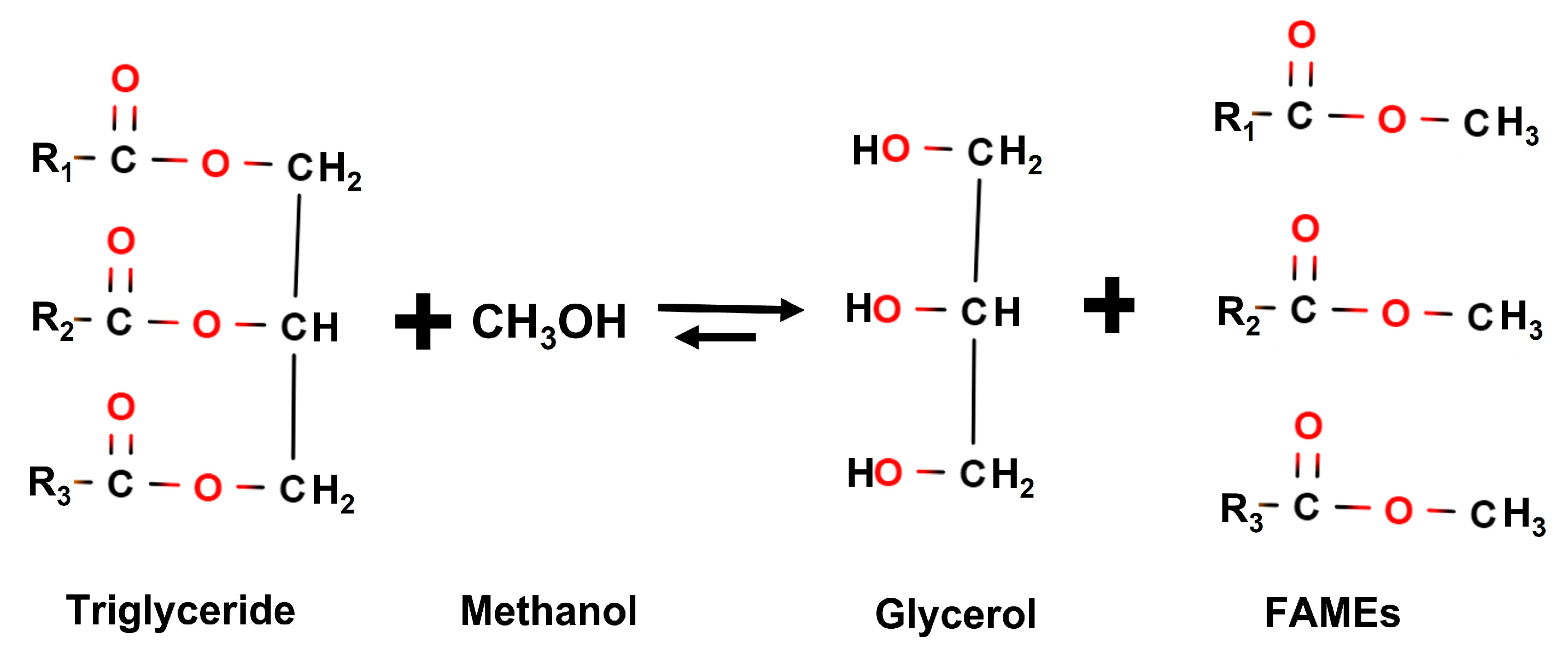
Figure 3.
Catalyst preparation, including: a) La(NO3)3∙6H2O impregnation; b) support drying with impregnated La; c) Ni(NO3)2∙6H2O impregnation; d) support drying with impregnated Ni.
Figure 3.
Catalyst preparation, including: a) La(NO3)3∙6H2O impregnation; b) support drying with impregnated La; c) Ni(NO3)2∙6H2O impregnation; d) support drying with impregnated Ni.
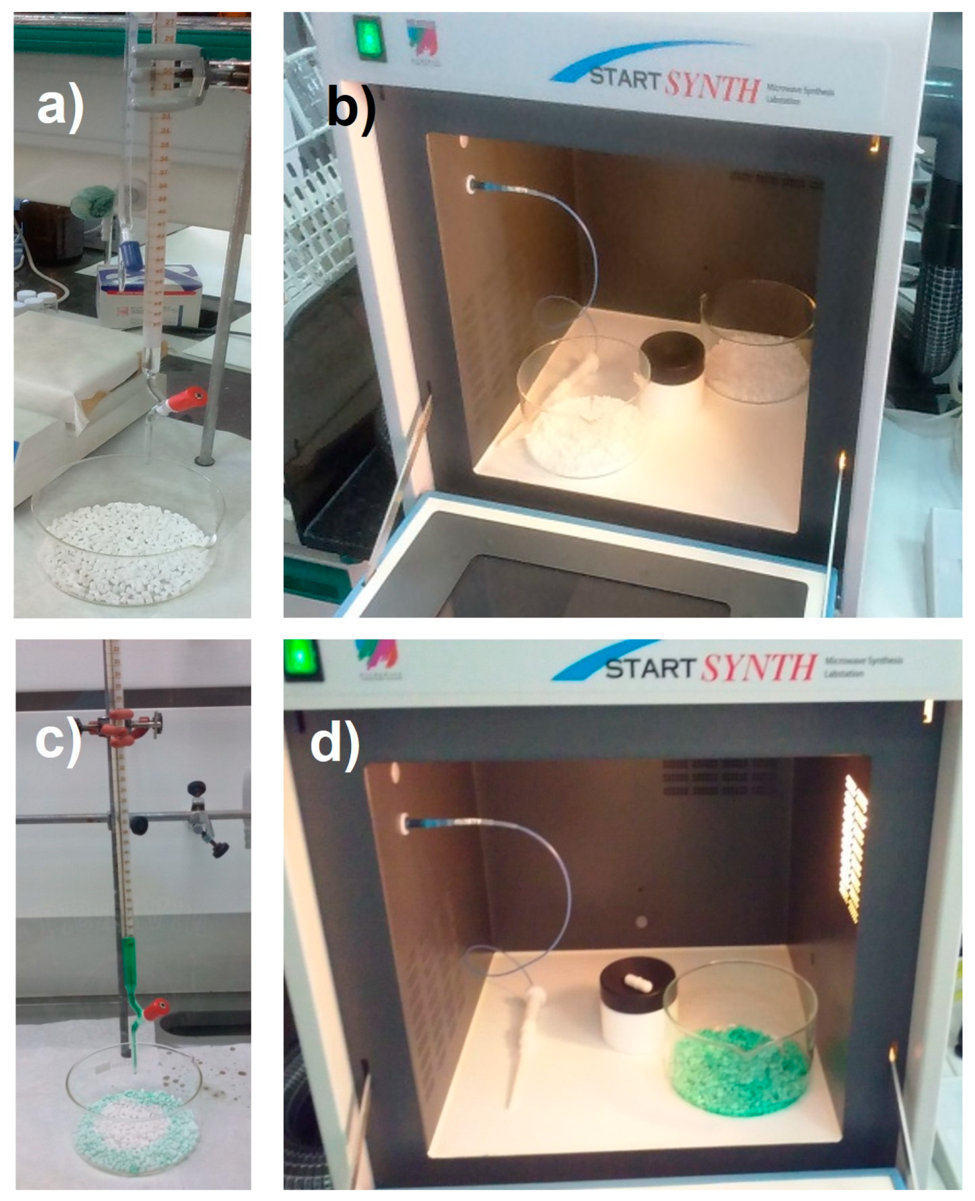
Figure 4.
Experimental arrangement, including: 1) heating jacket; 2) glycerol drying system; 3) dried glycerol tank; 4) peristaltic pump; 5) stirrer; 6) glycerol-water mixture tank; 7) peristaltic pump; 8) reactor; 9) basket; 10) oven; 11) distilled water tank; 12) peristaltic pump; 13) condensate tank; 14) gas heat exchanger; 15) peristaltic pump; 16) distiller; 17) flowmeter; 18) exhaust fumes.
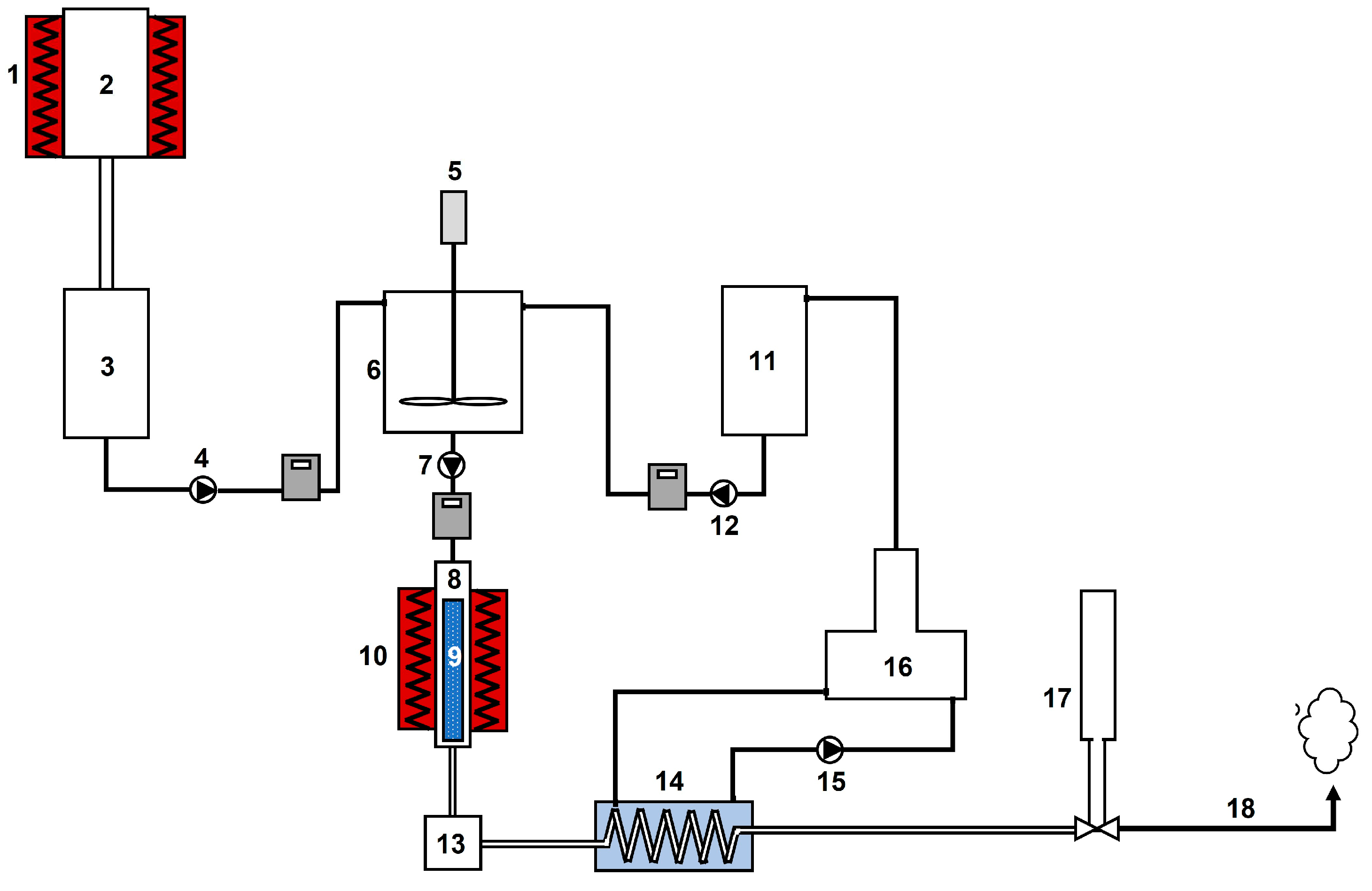
Figure 5.
Different components in glycerol steam reforming system: a) drying system; b) heating jacket; c) glycerol-water mixture tank; d) distiller; e) peristaltic pump; f) basket; g) reactor; h) oven; i) heat exchanger; j) flow-meter; k) gas chromatograph.
Figure 5.
Different components in glycerol steam reforming system: a) drying system; b) heating jacket; c) glycerol-water mixture tank; d) distiller; e) peristaltic pump; f) basket; g) reactor; h) oven; i) heat exchanger; j) flow-meter; k) gas chromatograph.
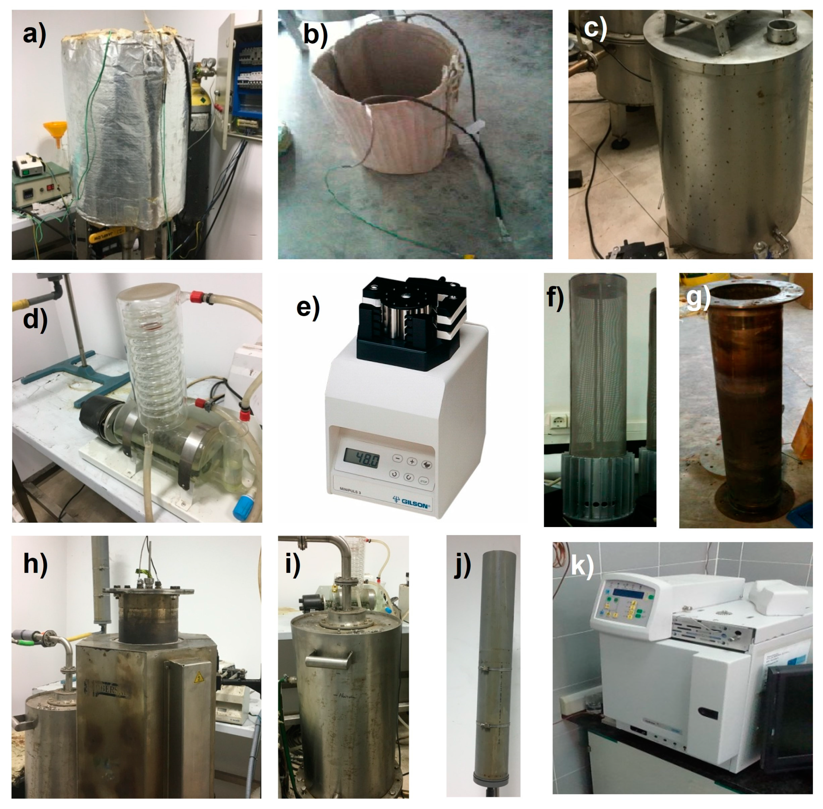
Figure 6.
Stabilization test for glycerol steam reforming (W/G = 0.7; flow = 40ml/min; T = 750 °C).
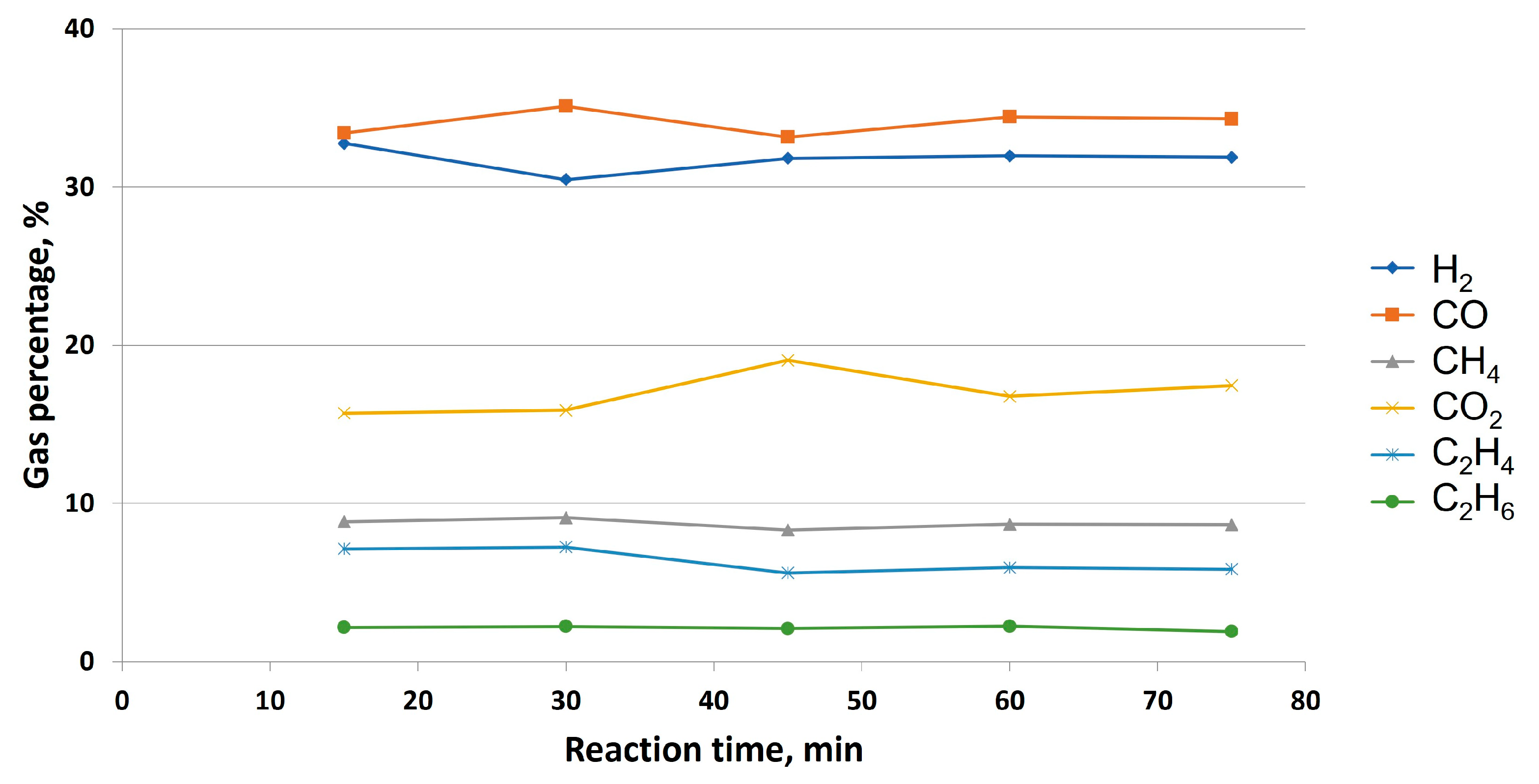
Figure 7.
Flow (a) and hydrogen percentage (b) in outlet gas in glycerol steam reforming without catalyst addition at different temperatures (W/G = 0.7; flow = 40ml/min).
Figure 7.
Flow (a) and hydrogen percentage (b) in outlet gas in glycerol steam reforming without catalyst addition at different temperatures (W/G = 0.7; flow = 40ml/min).
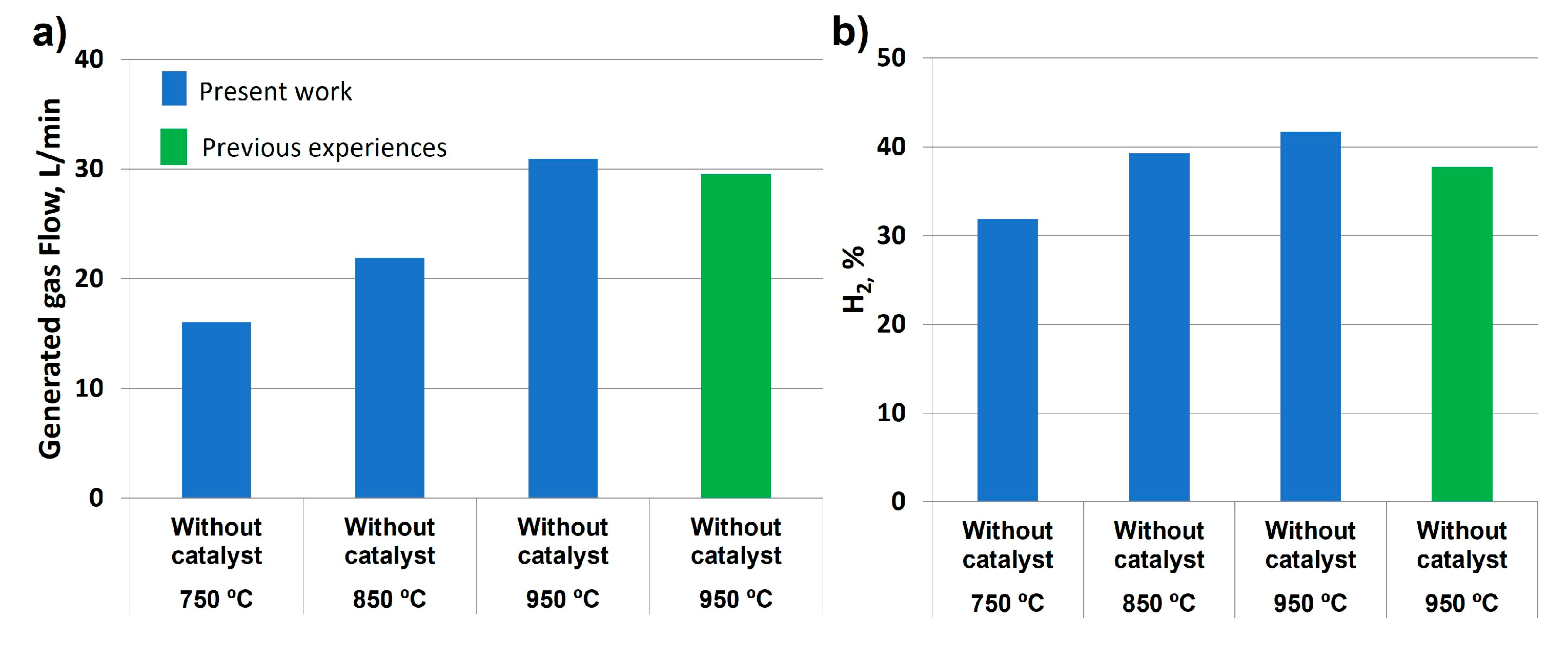
Figure 8.
Power and LHV in glycerol steam reforming without catalyst addition (W/G = 0.7; flow = 40ml/min).
Figure 8.
Power and LHV in glycerol steam reforming without catalyst addition (W/G = 0.7; flow = 40ml/min).
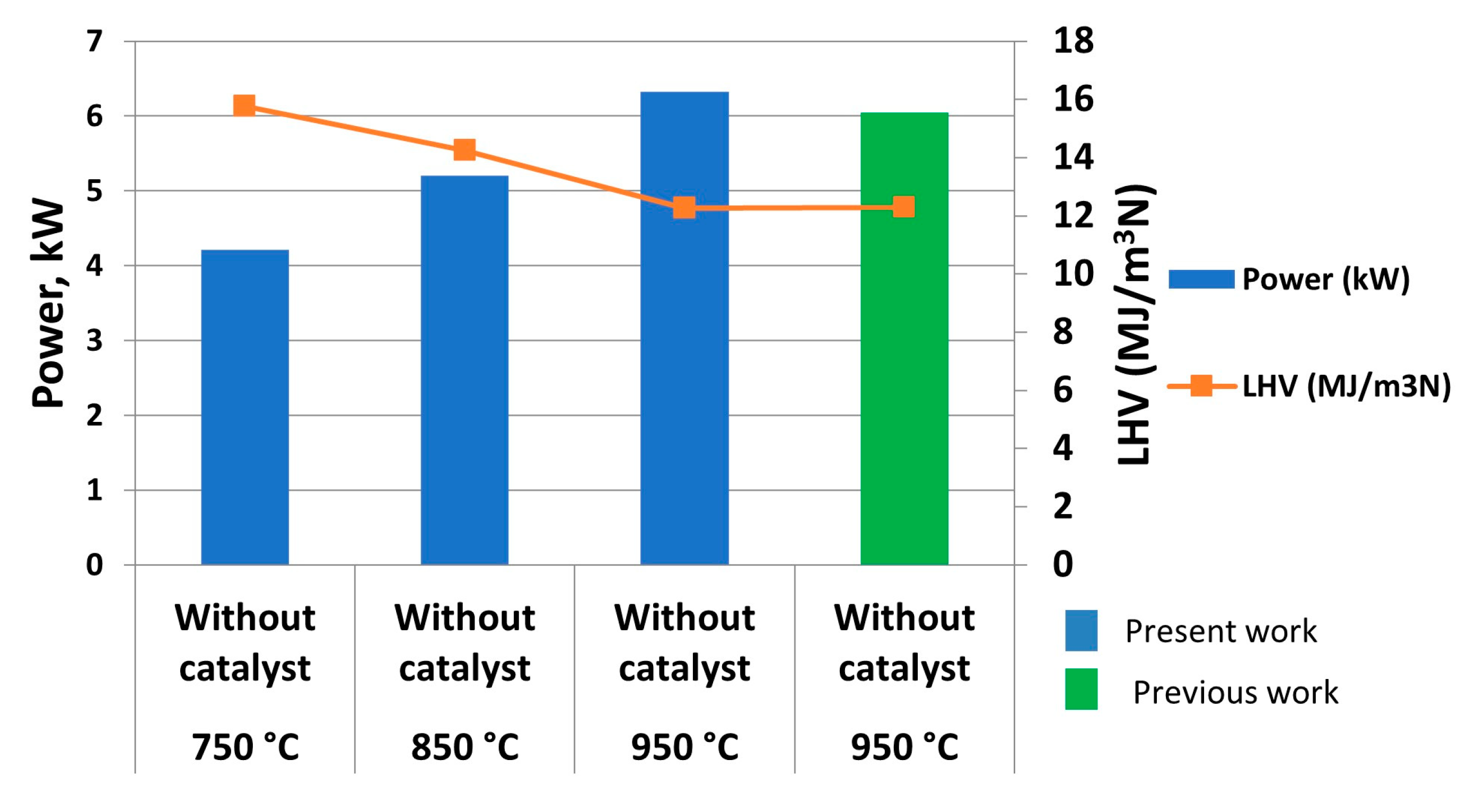
Figure 9.
Gas composition over time with different catalyst (NiO) additions: a) 12 %; b) 16 %; c) 20 %. The rest of operating conditions are common: W/G = 0.7, inlet flow = 40 ml/min, temperature = 750 °C.
Figure 9.
Gas composition over time with different catalyst (NiO) additions: a) 12 %; b) 16 %; c) 20 %. The rest of operating conditions are common: W/G = 0.7, inlet flow = 40 ml/min, temperature = 750 °C.
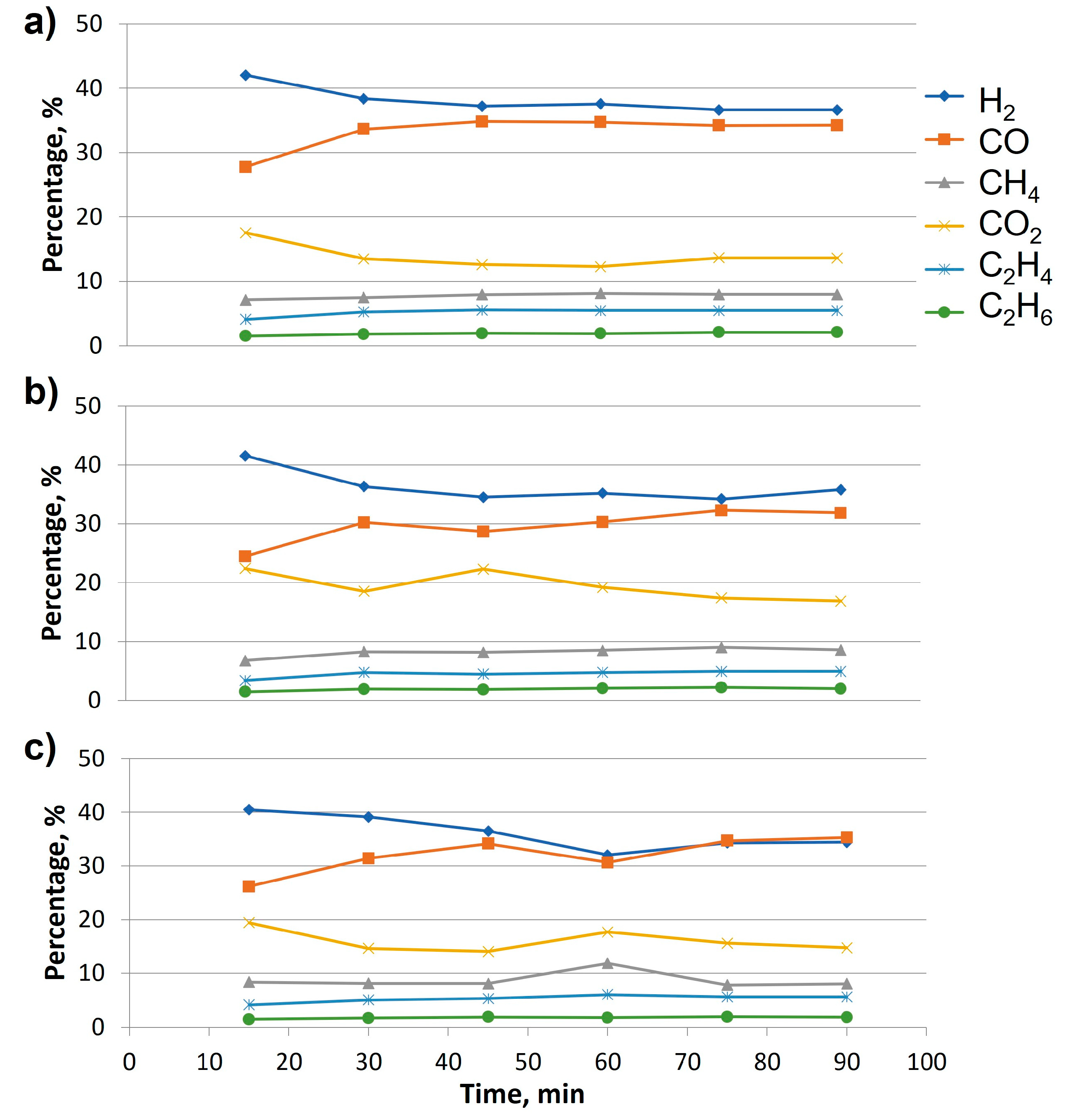
Figure 10.
Comparison of outlet gas flow (a) and hydrogen composition (b) during glycerol steam reforming at different catalyst concentrations and temperatures (W/G = 0.7, inlet flow = 40 ml/min).
Figure 10.
Comparison of outlet gas flow (a) and hydrogen composition (b) during glycerol steam reforming at different catalyst concentrations and temperatures (W/G = 0.7, inlet flow = 40 ml/min).
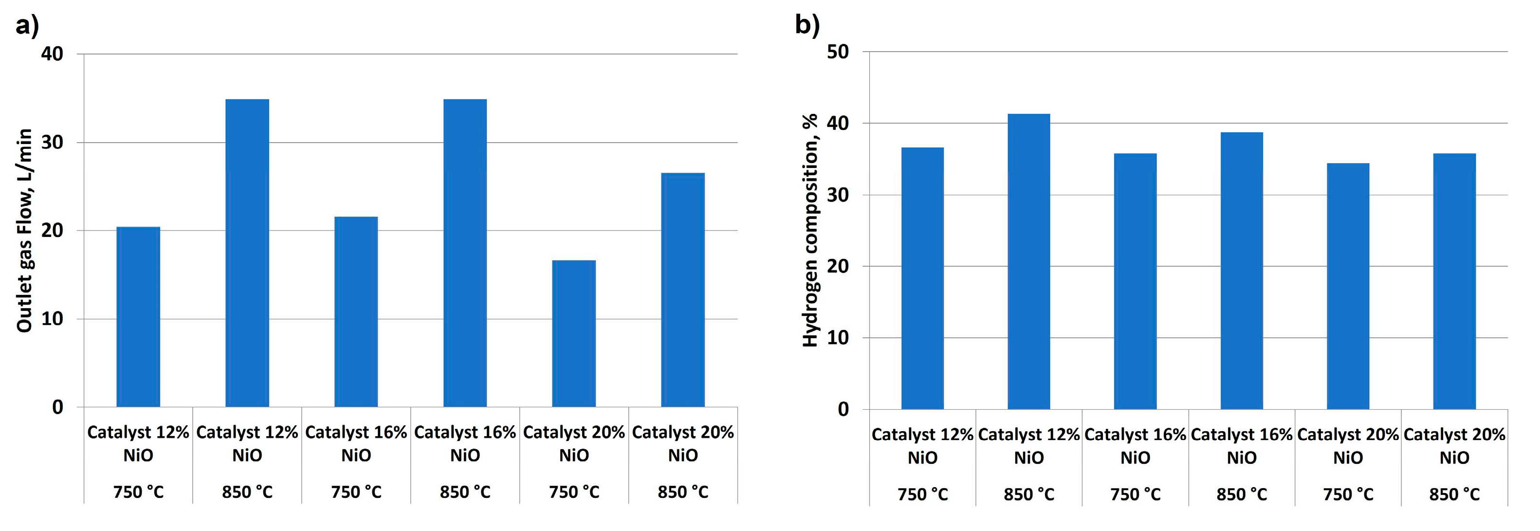
Figure 11.
Comparison of power and LHV obtained in glycerol steam reforming at different temperatures and catalyst concentrations (W/G = 0.7, inlet flow = 40 ml/min).
Figure 11.
Comparison of power and LHV obtained in glycerol steam reforming at different temperatures and catalyst concentrations (W/G = 0.7, inlet flow = 40 ml/min).
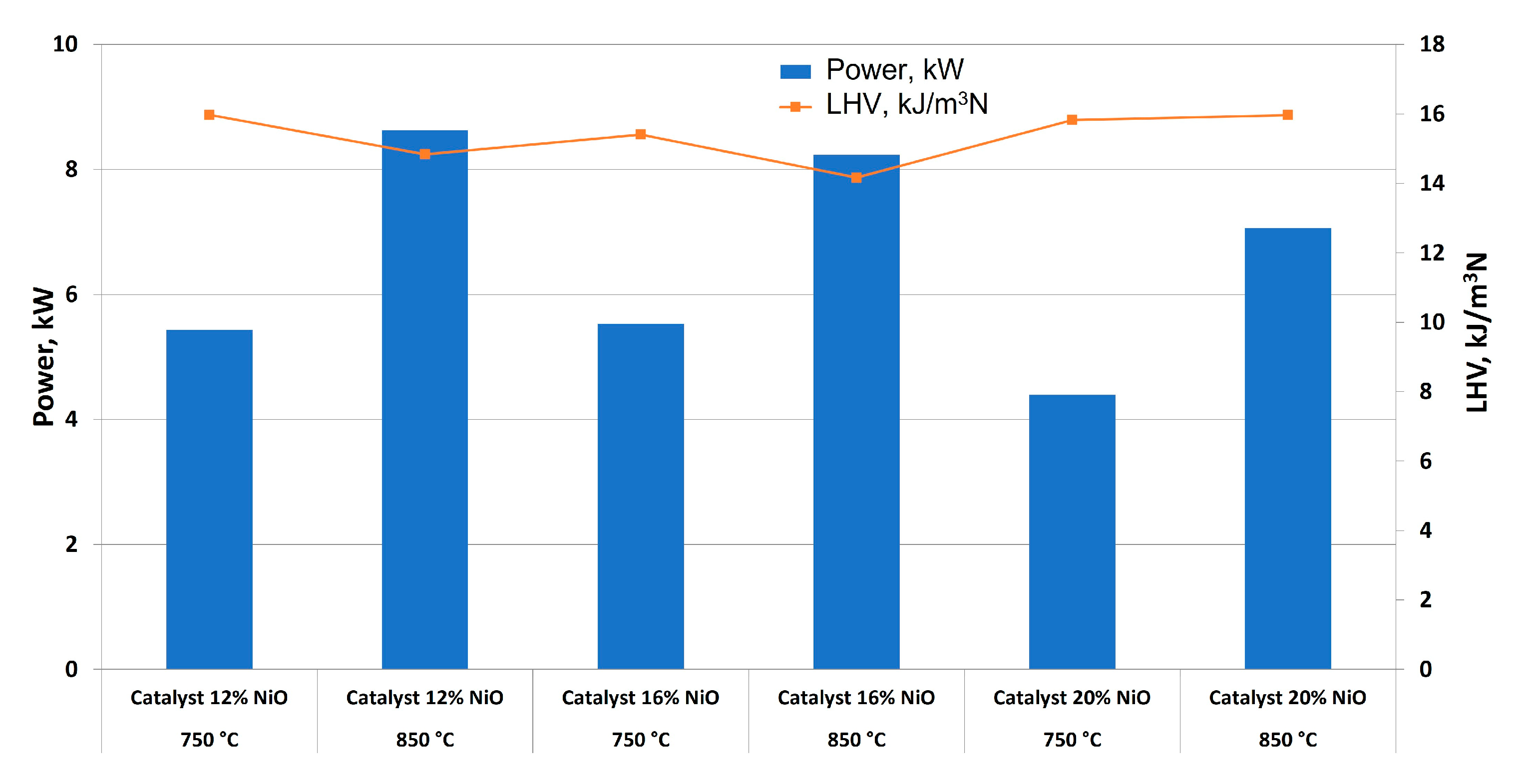
Figure 12.
Outlet gas composition for catalyst lifetime determination (NiO = 12 %; W/G = 0.7; inlet flow = 40 ml/min; T = 850 °C).
Figure 12.
Outlet gas composition for catalyst lifetime determination (NiO = 12 %; W/G = 0.7; inlet flow = 40 ml/min; T = 850 °C).
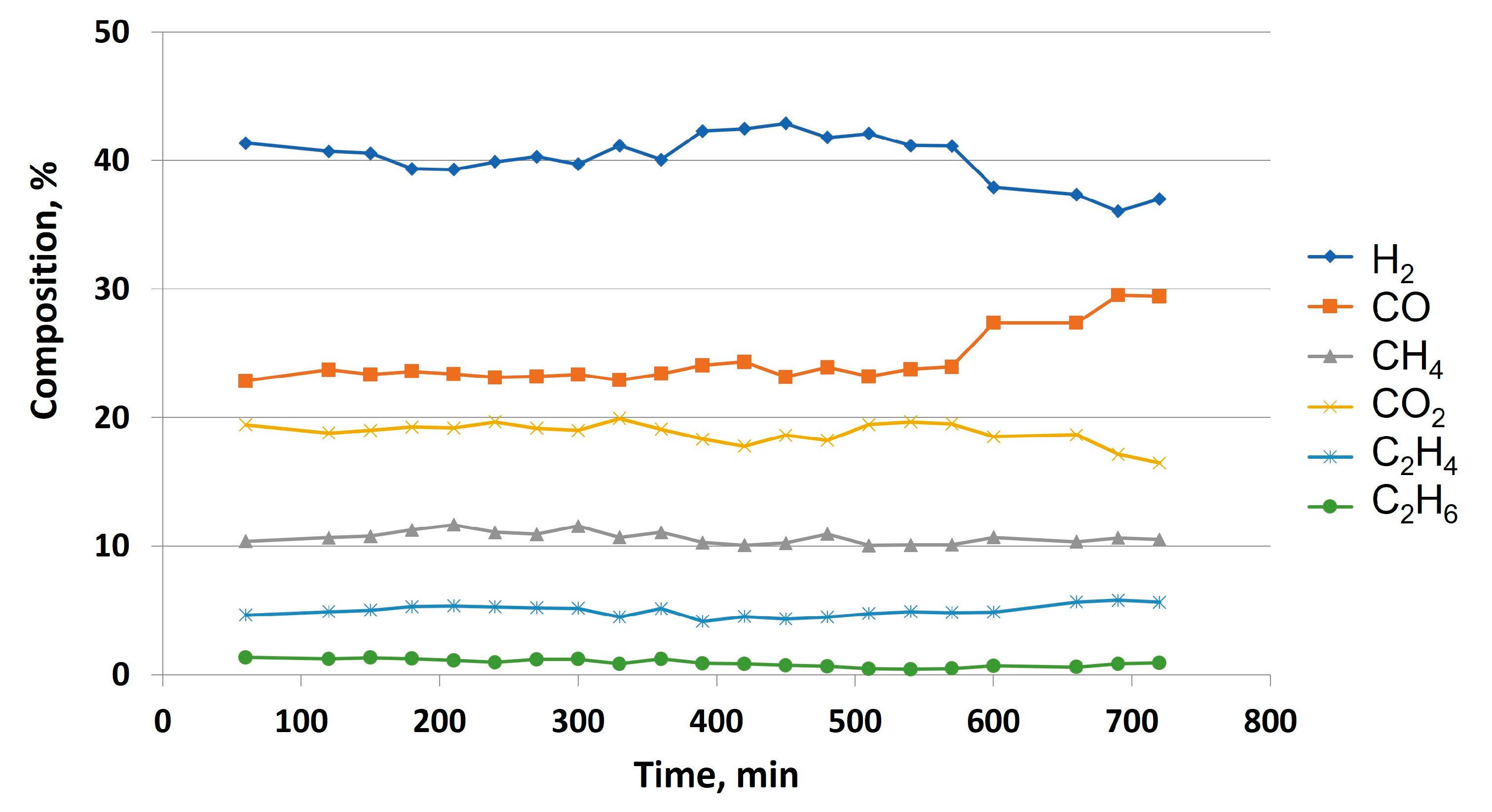

Table 1.
Glycerol properties and characteristics.
| Characteristics | Result |
|---|---|
| Nomenclature and synonyms | 1,2,3-Propanetriol, Glycerol, glycerine, |
| Molecular formula | C3H8O3 |
| Molecular structure | 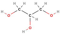 |
| Molecular weight (g/mol) | 92.09383 |
| Viscosity1 at 20 °C (Poise) | 15.0 |
| Density1, g/cm3 | 1.261 |
| Melting point1, °C | 18.2 |
| Boiling point1, °C | 290 |
| Others | Liquid at room temperature, colorless and hygroscopic |
1 Anhydrous and pure.
Table 2.
Crude glycerol: proximate and ultimate analysis.
| Proximate analysis, % | Result |
|---|---|
| Moisture | 16.37 |
| Volatile fraction | 75.18 |
| Fixed carbon | 0 |
| Ash content | 8.99 |
| Ultimate analysis, % | |
| C | 30.3 |
| H | 8.68 |
| N | 0.016 |
| S | 0.052 |
| HHV, kcal/kg | |
| Crude glycerol | 3332.41 |
| Dried glycerol | 3466.97 |
Table 3.
Improvements in glycerol steam reforming system carried out in this experience.
| Improvement | Details |
|---|---|
| Installation of an electrical board | A sensor connected to this electrical board was used to control water level in heat exchanger |
| Insulation joints in reactor | In order to avoid gas leakage in steam reforming reactor, two insulation joints were installed in the reactor, one for each cover. A leak test was carried out to check the effectiveness of these joints |
| Leak point detection and repair | The system was checked to avoid leak points. The exhaust tube presented leak points, and it was replaced. |
| Basket maintenance | The basket was cleaned during this experience to avoid rust, by using a polishing machine |
| Basket modifications | The reactor was modified, being a cylindrical piece with a constriction at the end of it, which was considered to modify the shape of the basket to be perfectly adapted at to the end of the reactor, forcing the gas to pass through the basket containing the catalyst |
| Peristaltic pump calibration | The pump was perfectly calibrated to make sure that the among of water required by the system was exact and constant |
Table 4.
Set of experiments for this work.
| Condition | Non-catalytic studies | Catalytic studies |
|---|---|---|
| W/G ratio | 0.7 | 0.7 |
| Flow, ml/min | 40 | 40 |
| Temperature, °C | 750-850-950 | 750-850 |
| Catalyst (NiO) concentration, %1 | 0 | 12, 16, 20 |
1 For all the catalysts produced, La2O3 concentration (used as promoter) was fixed at 5 %.
Table 5.
Experiments for catalytic glycerol steam reforming at different temperatures and catalyst concentrations.
Table 5.
Experiments for catalytic glycerol steam reforming at different temperatures and catalyst concentrations.
| W/G ratio | Inlet flow, ml/min | Temperature, °C | NiO concentration, % |
|---|---|---|---|
| 0.7 | 40 | 750 | 12 |
| 16 | |||
| 20 | |||
| 850 | 12 | ||
| 16 | |||
| 20 |
Table 6.
Comparison between non-catalytic and catalytic glycerol steam reforming (W/G = 0.7; inlet flow = 40 ml/min).
Table 6.
Comparison between non-catalytic and catalytic glycerol steam reforming (W/G = 0.7; inlet flow = 40 ml/min).
| Parameter | Non-catalytic studies at 950 °C | Catalytic studies at 850 °C |
|---|---|---|
| Outlet gas flow, l/min | 30.93 | 34.88 |
| Hydrogen content, % | 41.72 | 41.35 |
| Power, kW | 6.32 | 8.63 |
| LHV, kJ/m3N | 12.27 | 14.84 |
Disclaimer/Publisher’s Note: The statements, opinions and data contained in all publications are solely those of the individual author(s) and contributor(s) and not of MDPI and/or the editor(s). MDPI and/or the editor(s) disclaim responsibility for any injury to people or property resulting from any ideas, methods, instructions or products referred to in the content. |
© 2023 by the authors. Licensee MDPI, Basel, Switzerland. This article is an open access article distributed under the terms and conditions of the Creative Commons Attribution (CC BY) license (http://creativecommons.org/licenses/by/4.0/).
Copyright: This open access article is published under a Creative Commons CC BY 4.0 license, which permit the free download, distribution, and reuse, provided that the author and preprint are cited in any reuse.


