
Submitted:
10 August 2023
Posted:
10 August 2023
You are already at the latest version
Abstract
Gas turbine power plants have important roles in the global power generation market. The examines thermodynamically the impact of steam injection for a combined cycle including a gas turbine cycle with a two-stage turbine and carbon dioxide recompression. The combined cycle is compared with the simple case without steam injection. Steam injection’s impact is observed on important parameters such as energy efficiency, exergy efficiency, and output power. It is revealed that steam injection reduces exergy destruction in components compared to the simple case. The efficiencies for both cases are obtained. The energy and exergy efficiencies respectively are found to be 30.4% and 29.4% for the simple case, and 35.3% and 34.1% for the case with steam injection. Also, incorporating steam injection reduces emissions of carbon dioxide.
Keywords:
Combined cycle
; Gas turbine
; Steam injection
; Recompression Supercritical carbon dioxide
; Energy analysis
; Exergy analysis
1. Introduction
Energy and environmental impact analyses have gained importance in recent years due to increasing concerns over hydrocarbon fuel consumption and environmental pollution. Recently, international agreements have led to a decrease in fuel consumption and environmental pollution, as well as the retirement of many fossil fuel power plants. The electricity production market is also changing. Between 2015 and 2035, nearly 90 GW of fossil fuel power plant capacity is going to be retired in the United States [1]. Meanwhile, natural gas power plants are gradually increasing in number. Gas turbines play a prominent role in electricity generation technology today, with the potential to grow. Nearly 80 GW of new gas turbine power plant capacity is predicted to enter the electricity generation market by 2035 [2].
Decreasing fuel consumption for a given output makes power plants operate more economically by reducing fuel consumption costs. However, a capital cost investment is normally required to obtain high efficiency and is offset by fuel cost savings. Gas turbine cycles can work on an extensive range of fuels comprising natural gas, which exhibits cleaner combustion than other fossil fuels [3,4,5]. In designing new gas turbine units, it is often advantageous to increase turbine inlet temperatures and pressure ratios. Other beneficial gas turbine modifications include the use of intercoolers and interstage turbine reheat [6,7,8]. Gas turbines power generation plants can also incorporate solid oxide fuel cells [9,10,11].
Nowadays, the utilization of gas turbine power plants incorporating steam injection to the combustor with natural gas is one of the most effective ways for the reduction of NOx emissions. Such plants also have relatively good energy efficiencies. Exhaust gases can be used to produce superheated steam, which is one of the most effective heat recovery methods [12].
A thorough review of wet gas turbine research [13] identified those cycles having the highest future potential. Romeliotis and Mathiodakis [14] analyzed the effect of water injection on engine efficiency and performance as well as on compressor behavior. Techniques were investigated for water injection through internal methods that ascertain water injection influences on the gas turbine and on compressor off-design performance. Enhanced performance for the gas turbine was demonstrated with water injection. Eshati et al. [15] presented a model for industrial gas turbines to investigate the impacts on heat transfer and cooling of turbine blades of the air-water ratio. It was shown that, with a rise in the air-water ratio, the cooling temperature of the blade inlet is reduced along the blade opening. The temperature of blade metal in each part is reduced as the air-water ratio increases, and this also increases the creep life of the blade.
Renzi et al. [16] evaluated the effects of syngas (produced gas) and its performance in a gas microturbine with steam injection (SI). The results show that the energy of the synthesis gas in the combustion chamber (CC) reduces NOx emissions by nearly 75%. In contrast, the CO emissions increase slightly with natural gas combustion. It was found that the maximum value of injected steam in the combustion chambers of the gas turbine system is 56 g/s. Mazzocco and Rukni [17] investigated thermodynamically a parallel analysis for solid oxide fuel cell plants, hybrid gas turbines with steam injection, gasification power plant combinations, and simple power plants. For the optimized power plants, the energy and exergy efficiencies were shown to be 53% and 43%, respectively, significantly more than the related values for conventional 10 MW power plants fed with biomass. A thermoeconomic analysis identifies the average cost of electricity for the arrangements with the best performance at 6.4 and 9.4 c€/kW, which is competitive in the marketplace.
Using energy, exergy, economic and environmental analyses, Amiri-Rad [18] investigated steam injection and heat recovery for a gas turbine having steam injection in addition to an anti-surge system. Waste heat recovery via a heat exchanger produces steam from the gas turbine exhaust. Finally, the method employed introduces the optimal steam injection conditions for the combustion chamber; for a relative humidity of 10% and an ambient temperature of 38°C, the optimal steam temperature is observed to be 318.5°C. Steam injection to the gas turbine with integrated thermal recovery at the optimal steam temperature reduces the cost of electricity production by 25.5% and increases the net generated power by 56 MW and the energy efficiency by 4.6%.
Ahmed [19] examined a modified gas turbine by injecting steam between the combustion chamber exit and turbine entrance. Current optimized cycles having steam injection yield higher power output and efficiency, which results in lower specific costs. Bahrami et al. [20] improved gas turbine transient performance through steam injection during a frequency drop. A control system is presented that utilizes, during the frequency drop, an auxiliary input of steam injection to enhance gas turbine transient performance. The control algorithm’s performance was investigated at several conditions, demonstrating that steam injection increases performance notably for the standard control algorithm, particularly near full load conditions.
Sun et al. [21] performed energy, exergy, and exergoeconomic investigations of two systems using supercritical CO2 combined with a gas turbine. They considered the effects on energy efficiency of five parameters, including temperature difference of the inlet and outlet for exhaust gases, pressure ratio, and compressor inlet pressure. They also obtained values of exergy efficiency and cost per kilowatt hour. Comparing the traditional combined cycle and the design proposed, they reported that the S-CO2 cycle has competitive economic performance without any significant thermodynamic performance loss.
In this present work, a gas turbine cycle using a working fluid of carbon dioxide is examined, with steam injection to the combustion chamber (SIGTSC) and without (GTSC). Then, the cycle variations are compared. The novelty of this work lies mainly in combustion chamber steam injection for this new configuration with in-depth analysis to elicit more realistic results. The steam injection also improves the system’s environmental characteristics like pollutant emissions, which are important today.
2. Description of system
Figure 1 depicts the considered system, which consists of a SCO2 recompression bottoming cycle and a Brayton topping cycle as the cycle. Air enters the air compressor at ambient atmospheric conditions; then air, methane, and superheated steam flows mix at different conditions and the combustion process occurs. Hot exhaust gases are conveyed to the two-stage gas turbine where work is produced and the temperature decreases. The SCO2 subsystem utilizes exhaust gases as a high temperature heat source. The SCO2 cycle is described elsewhere [22,23]. After transferring heat from the output gases in the HEX heat exchanger, the cooled gases enter the HRSG and supply the superheated steam used by the combustion chamber. In this study, the efficiency is examined for the power generation system with two subsystems (gas turbine cycle with steam injection and two-stage turbine and SCO2 subsystem) in a combined form, as are the effects on the whole system of steam injection percentage to the combustion chamber.
Various approximations and simplifications are invoked during the analysis:
- All gases are assumed ideal with specific heat and enthalpy changes depending on temperature, except for injected steam.
- Nitrogen and oxygen compression factors are assumed to be ideal even at the lowest temperature and highest pressure of the analysis.
- Due to thermodynamic restrictions, the turbine inlet temperature cannot exceed 1440 K.
- The air entering the compressor is considered completely dry and contains 21% oxygen and 79% kmol nitrogen on a molar basis.
- The combustion chamber efficiency in the gas turbines utilizing natural gas and methane in gas phases is very high and, in most studies, a value of 99% is considered.
- Combustion is considered to be steady and the CC is considered a well-stirred reactor (WSR).
- The temperature of combustion is based slightly on the stoichiometric rich side. This is done because Lefebvre [24] showed for a fixed enthalpy of reactants that the lower is the product mixture average specific heat, the higher is the resulting flame temperature because of the richer average specific heat for the products.
- Pressure drops due to friction are negligible [25].
- Pressure losses and heat losses in all heat exchangers and pipelines can be disregarded [22].

Table 1.
Input data for modeling the considered power generation system.
| T0=298.15 K | Pr1=10 | T10=305.15 K | ηc,is=0.87 |
| P0=101.325 kPa | Tfuel=298.15 K | P10=7400 kPa | ηcc=0.99 |
| T1=298.15 K | Ts=573.15 K | ε LTR =0.85 | ηt,is=0.89 |
| P1=101.325 kPa | s=5% | PRc=2.2-4.2 | ηp,is=0.70 |
| 1=1 kg/s | ϕ=0.4017 | ηt,is,Bottom=0.9 | ε HTR=0.85 |
| Pexh=101.325 kPa | TIT=1300 K | ηis,mc,rc=0.85 |
3. Modeling and simulation
3.1. Energy analysis
The first law of thermodynamics is employed to balance energy rates for the power generation components. Following conservation of mass principles, mass flow rates and molar flow rates of flows of working fluids are determined. For a control volume operating at steady state, general rate balances for mass and energy respectively are:
Here, cv and cv respectively denote the power and the heat transfer rate into the control volume.
3.1.1. Combustion modeling
3.1.1.1. Combustion process with steam injection
In the present work, the incoming air from the compressor is mixed in the combustion chamber with fuel (methane), while superheated steam is injected through the process to control the emissions of pollutants to the environment. The chemical reaction occurring in the CC is as follows [26,27]:
Here, φ and ε are the equivalence ratio and the molar air-fuel ratio, respectively, while x denotes the injection molar ratio of H2O. These quantities can be written respectively as follows: [26,27].
In equation (4), s is the steam injection ratio. Usually designs of gas turbines allow up to 5% of steam injection into the CC [28]. The molar balance for the 10 species in equation (1) of the combustion reaction related as follows:
Also, there are six chemical balances among the species in of combustion products according to the following [26]:
The chemical equilibrium constants for the above reactions are obtained according to the following equations [26,27]:
In equation 17, is the temperature of combustion products. Also, denotes the variation in Gibbs function of chemical equilibrium reactions in the atmospheric pressure, and are obtained from the following:
In the above equations, is the molar Gibbs function of species i in exhaust gases and chemical equilibrium at the atmospheric pressure is obtained using the following [29]:
After determining the chemical equilibrium constant and solving the set of chemical equations of the combustion reaction, the numbers of moles of products in the CC are determined.
3.1.1.2. Combustion process without steam injection
For the simple conventional gas turbine system without steam injection, the combustion process under complete chemical equilibrium conditions is as follows:
The molar balances for the species in the chemical equation are presented in Equations 32-35:
The chemical equilibrium equations are exactly the same as the steam injection mode (see Equations 11-29).
3.1.2. Analysis of expansion
For the high operating pressure associated with the proposed gas turbine system, a two-stage turbine is utilized in the configuration, as shown in Fig. 1. The HPT and LPT pressure ratios can be written as [30]:
where
Energy balance equations of the component used in the proposed plant are presented in Table 2.
The first law efficiency expressions for each subsystem of the plant in both the steam injection and simple modes are as follows:
3.2. Exergy analysis
We now write exergy rate balances for the power generation system components and to determine the irreversibility rate of each. For a control volume at steady state, a general exergy rate balance can be written as [31]:
Here, represents the exergy rate with heat transfer while denotes the temperature where heat is transferred and the internal irreversibility rate, which is always a positive quantity. The working fluid’s total exergy flow rate is the sum of the thermodynamic and chemical flow exergy rates [31]. That is,
For a working fluid, the exergy flow rate can be written as [31]:
where i, , and respectively denote for the working fluid at state i mass flow rate and specific enthalpy and entropy, and and respectively are for the working fluid at the dead state denote specific enthalpy and entropy. The chemical exergy flow rate for a mixture of ideal gases is expressible as follows [31]:
Here, denotes species i molar fraction for the mixture, and standard chemical exergy of an ideal gas. According to Figure 1, exergy rate balance relationships are listed in Table 3 for each power generation system device.
To examine the quality of energy obtained from the power generation system, the exergy efficiency (sometimes referred to as second law efficiency) is used. For each of the existing subsystems, as well as the overall system, the exergy efficiencies are as follows:
The carbon dioxide emission index can also be determined following equation [9]:
4. Results and discussion
4.1. Validation
4.1.1. Combustion and chemical equilibrium equation
To verify and validate the correctness of the number of moles obtained from combustion products for the main combustor with steam injection, results from the present analysis are contrasted with the results of reference [21]. Thermodynamic modeling is performed of the CC using the molar balance and the chemical equilibrium conditions of the combustion products, and the molar fractions of the resulting combustion gases are contrasted with the results in reference [21] in Table 4.
4.1.2. SCO2 subsystem
4.2. Power generation system case study
Results are given in Table 6 and Table 7 for the GTSC and SIGTSC, respectively, following the power generation system input data of Table 1. Energy and exergy results are provided in Table 8 for both systems.
Figure 2 depicts a system Sankey diagram, showing the exergy rate of each component flow, for the case when the air pressure ratio is equal to 10, the percentage of steam injection is 5%, and TIT is equal to 1300 K. Also, the pressure ratio in this figure for the SCO2 subsystem is 2.8. The equivalence ratio is considered to be 0.4017.
Figure 3.a demonstrates the rates of consumed or generated electric powers of the components of the proposed systems. The negative value of produced power indicates components with power consumption. Component exergy destruction rates are also provided in Figure. 3.b. According to this figure, the highest and lowest exergy destruction rates are for CC and HEX, respectively (except the pump exhibits the lowest exergy destruction rate for SIGTSC).
4.3. Parametric study
Figure 4.a illustrates the impact of the equivalence ratio of CC on net output power. It is seen that, with rising equivalence ratio, the net output power is augmented. Meanwhile, as steam injection rises from zero to 10%, the net output power rises. Steam injection raises the mass flow rate of the cycle, increasing the net power generation. Augmenting the equivalence ratio boosts the fuel flow rate. Therefore, the flow rate of the output products also increases, and thus the output work rises. Also, at a specified equivalence ratio, the input flow increases with an increase in the amount of steam injection, and as a result the output work increases.
Figure 4.
a. Effect on net output power production of CC equivalence ratio.
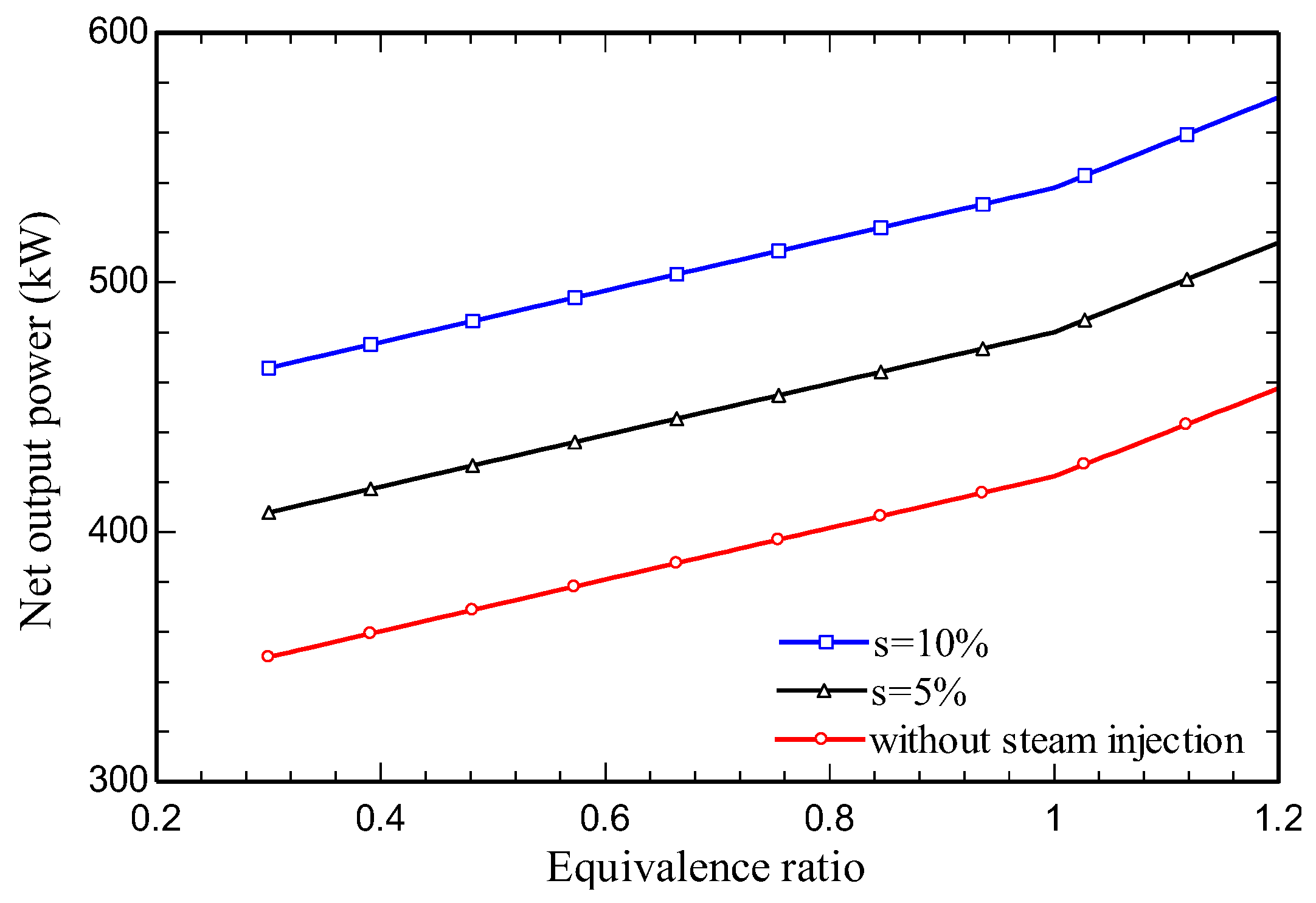
Figure 4.b. shows the influence of equivalence ratio on system exergy destruction rate. In this Figure, the equivalence ratio rise increases the exergy destruction rate until the stochiometric equivalence ratio decreases. Increasing the quantity of steam injection causes the exergy destruction rate to diminish for a specified equivalence ratio, highlighting the advantage of steam injection in gas cycles.
Figure 4.
b. Effect on total exergy destruction rate of equivalence ratio.
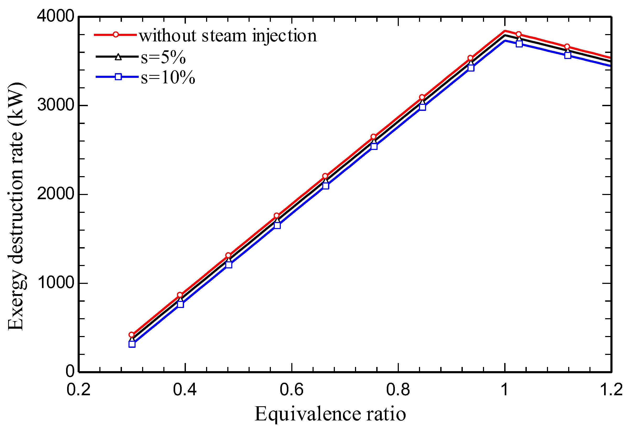
Figure 4.c illustrates the variation with equivalence ratio of CO2 emission index. With a rise of the equivalence ratio, the mass flow rate of carbon dioxide increases until reaching the stochiometric equivalence ratio, and then decreases. According to the increasing trend of carbon dioxide mass flow rate and specific work, the increasing slope of mass flow rate is higher than the specific work; as a result, the slope of the graph is increasing, but in the rich state, the increasing slope of specific work is higher than the mass flow rate of carbon dioxide, which is shown in Figure 4.a, and the general trend is decreasing. According to Figure 4.c the value of the CO2 emission index is reduced as the amount of injected steam into the CC increases.
Figure 4.
c. Effect on CO2 emission index of equivalence ratio.
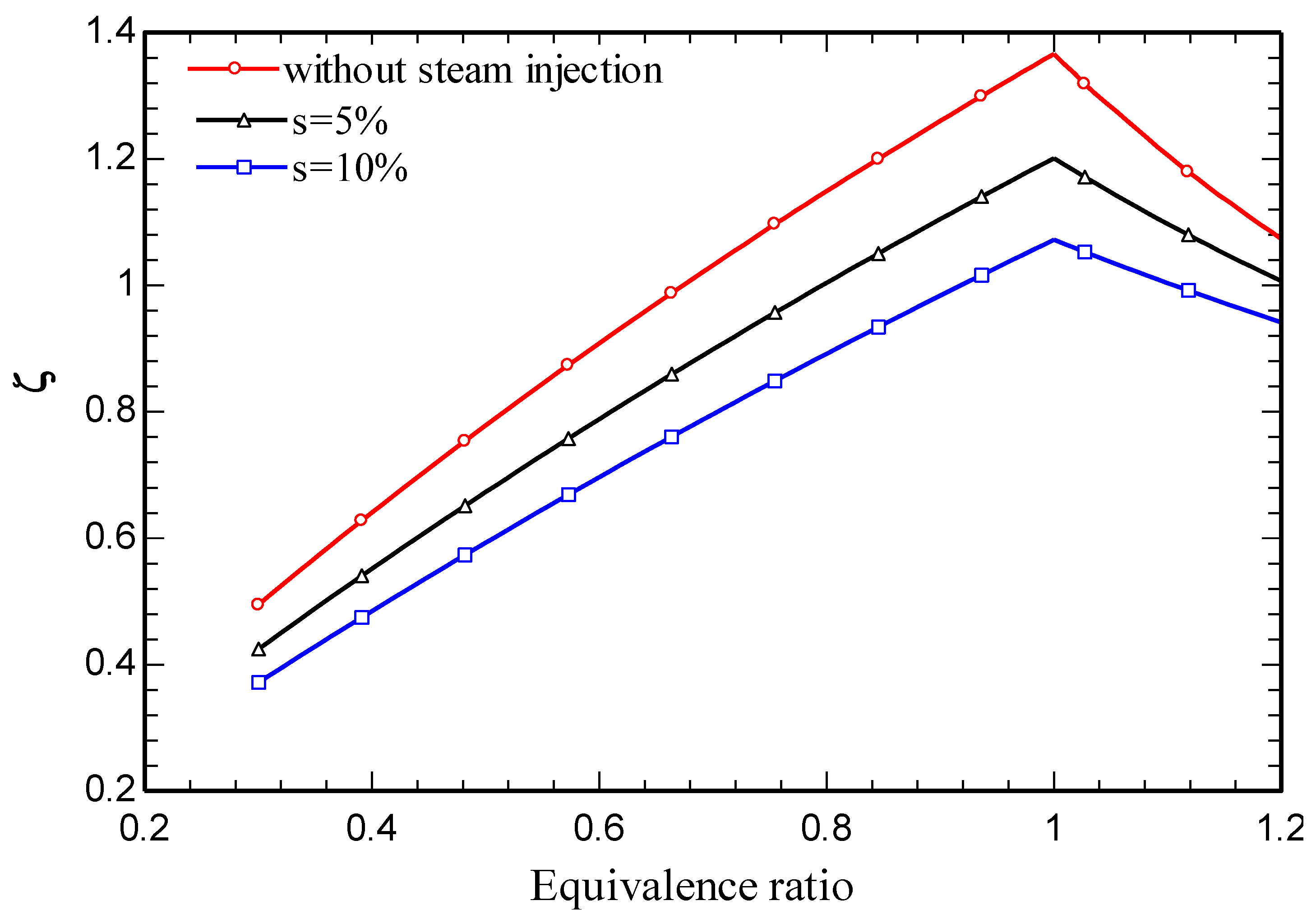
Figure 4.d illustrates the energy efficiency for the overall system as a function of equivalence ratio. An equivalence ratio rise is seen to increase the fuel mass flow rate, lowering the overall energy efficiency. The energy efficiency rises with steam injection to the CC.
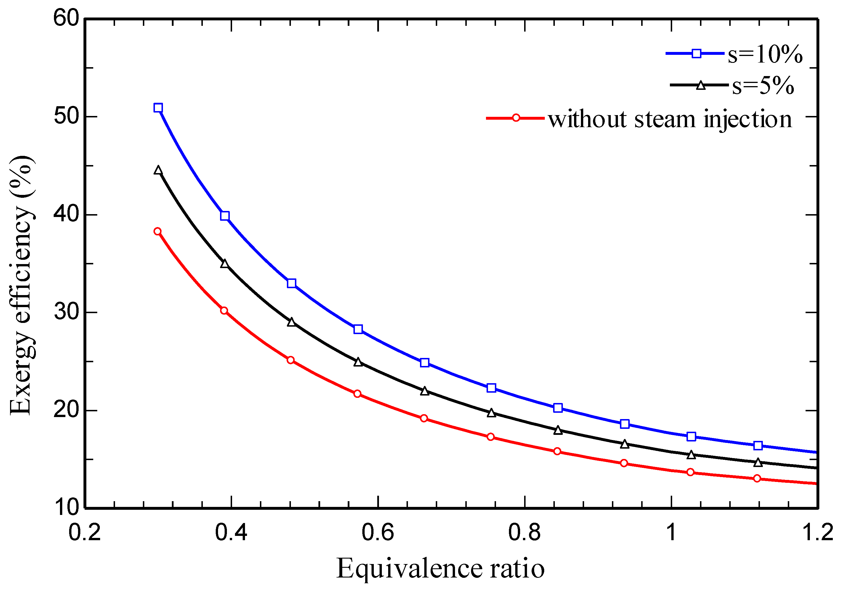
Figure 4.e depicts the influence on the exergy efficiency of the overall system equivalence ratio. The trends in exergy and energy efficiency mirror each other, as described above.
Figure 4.
d. Effect on system energy efficiency of equivalence ratio.
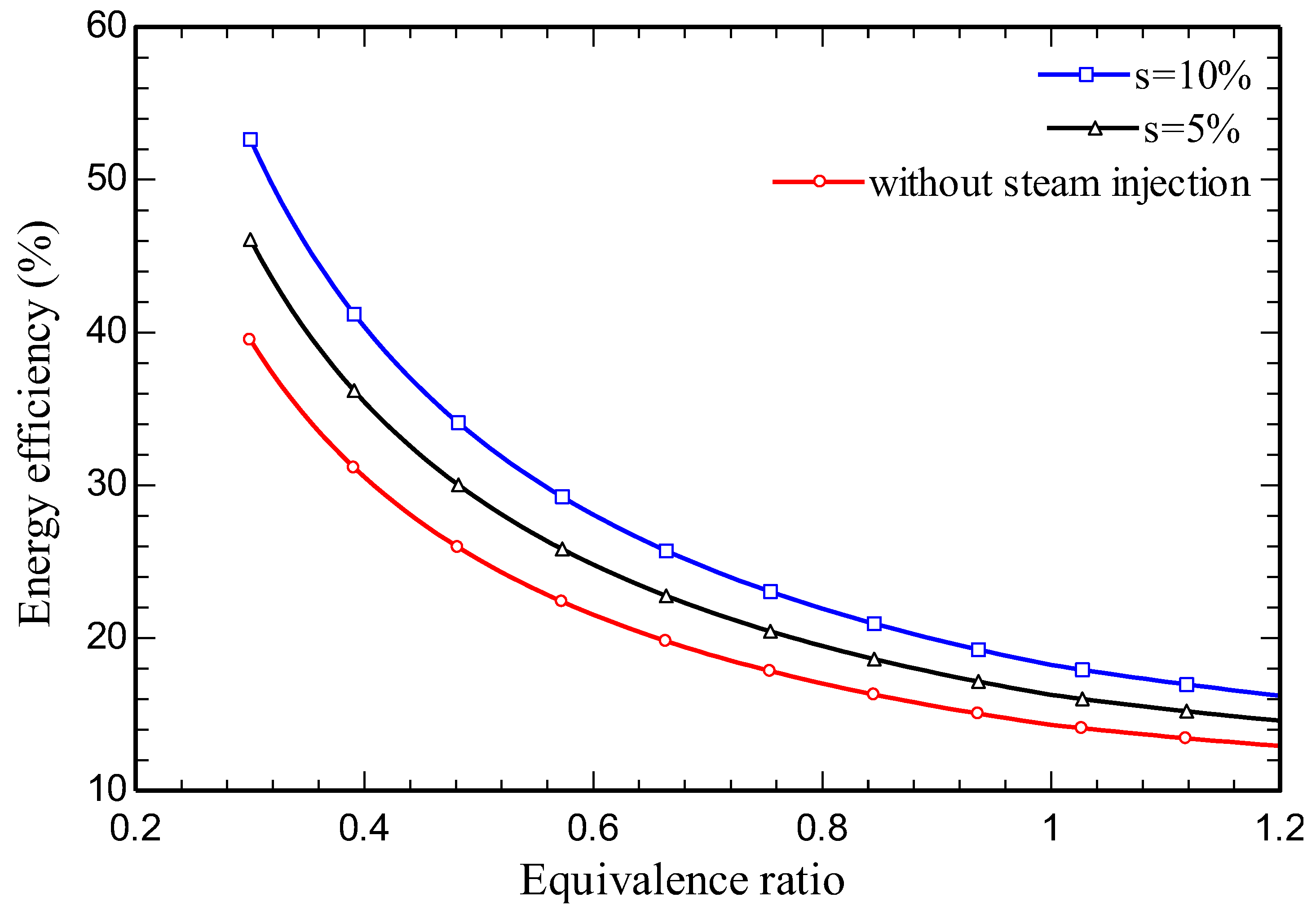
Figure 4.
e. Effect on system exergy efficiency of equivalence ratio.
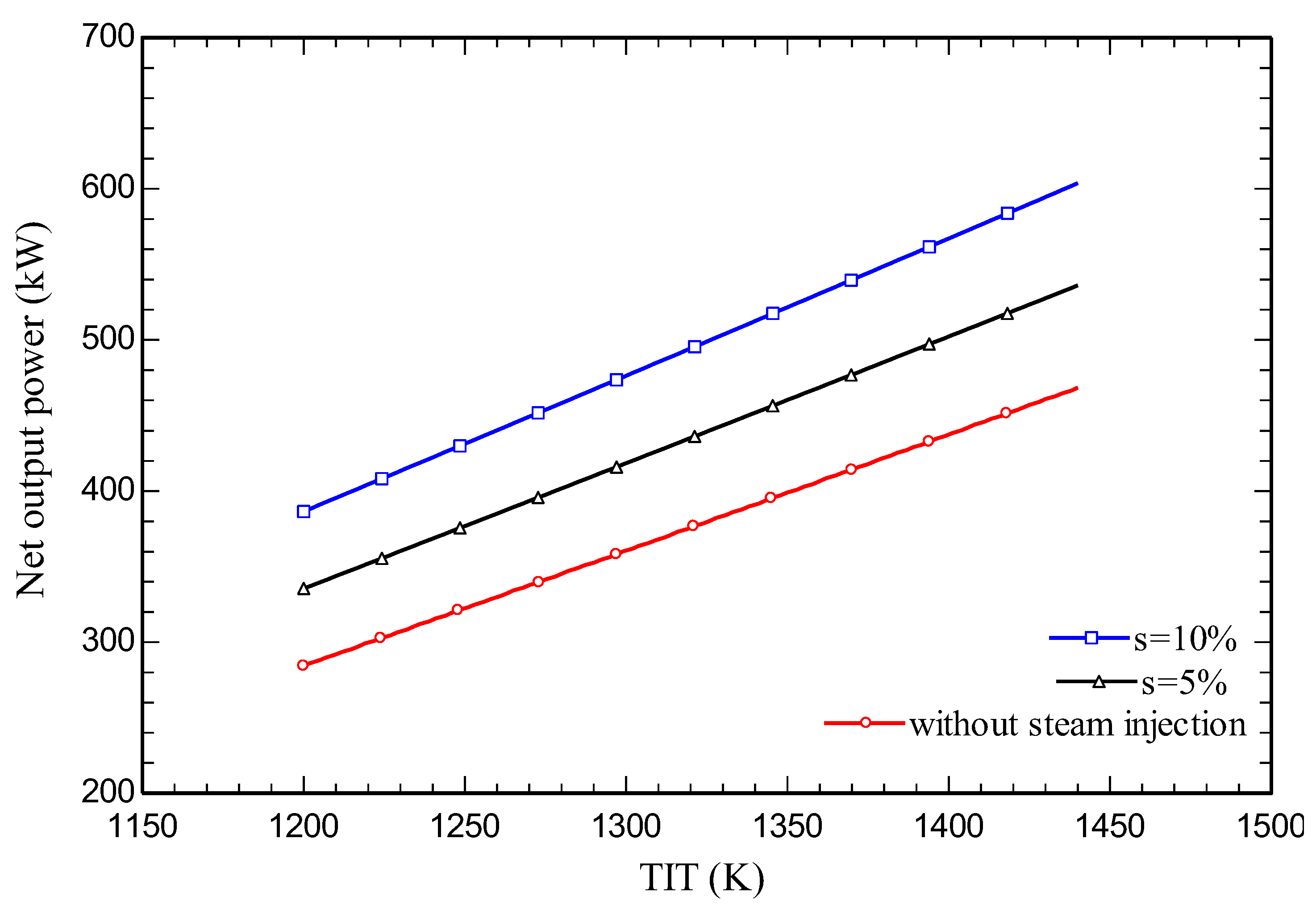
Effects of variations of turbine inlet temperature (TIT) are shown in Figure 5.a-e for five main performance parameters. Figure 5.a illustrates the impact of varying TIT on net output power. As TIT increases, the specific work exhibits an upward trend. This reveals that, with an increase in temperature at the outlet, the enthalpy of the input gases to the turbine also increases and as a result, output work increases. Like the trend described above, the more steam that is injected into the CC, the greater is net output power derived.
Figure 5.
a. Effect on system net output power of variation of TIT.
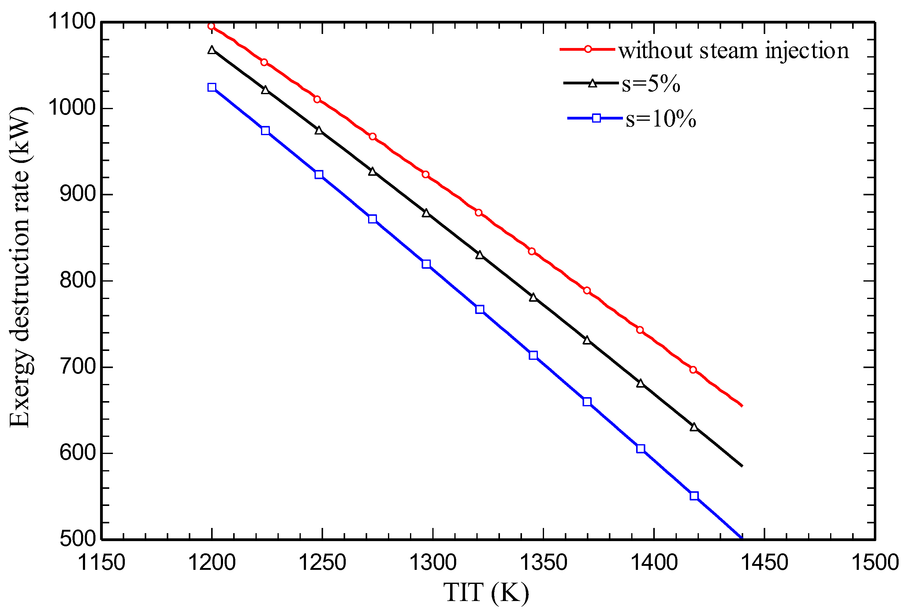
Impacts on total exergy destruction rate of variations of TIT are illustrated in Figure 5.b. Increasing TIT is seen to decrease total exergy destruction rate. As temperature increases, due to approaching the adiabatic flame temperature, the resulting heat loss decreases, so the exergy destruction rate declines. According to Figure 5.b, for a constant TIT, the exergy destruction rate diminishes with increasing steam injection.
Figure 5.
b. Effect on total system exergy destruction rate of variation of TIT.
Effects on carbon dioxide emission index of varying TIT are illustrated in Figure 5.c. As shown in the previous section, the exergy destruction rate of the overall system rises with TIT; Figure 5.b. explains and justifies this behavior.
Figure 5.
c. Effect of variation of TIT on CO2 emission index of the system.
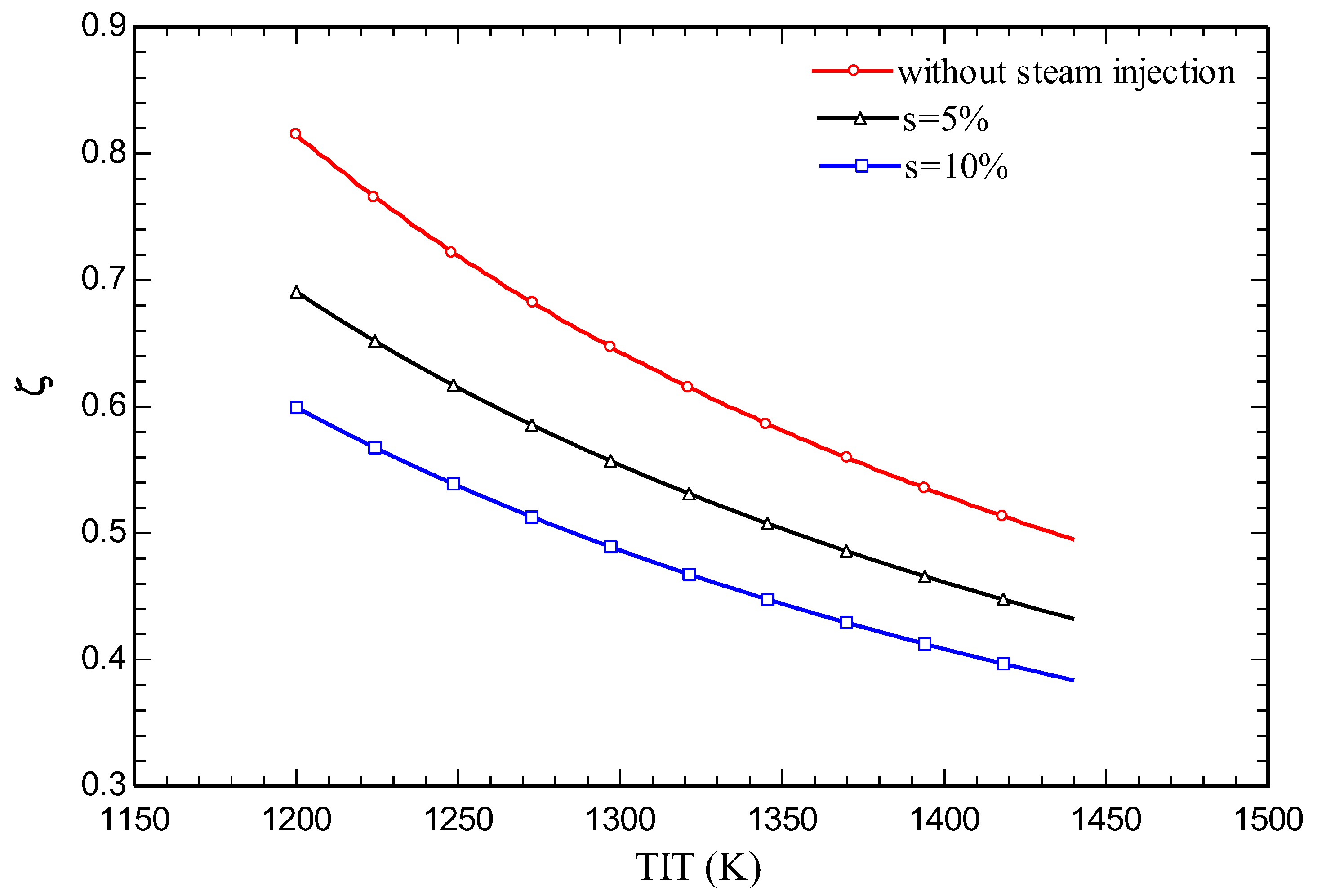
Figure 5.d and Figure 5.e show respectively the effects on energy and exergy efficiencies of variations of TIT. As TIT rises, energy and exergy efficiencies exhibit similar upward trends, as anticipated.
Figure 5.
d. Effect of variation of TIT on energy efficiency of the system.
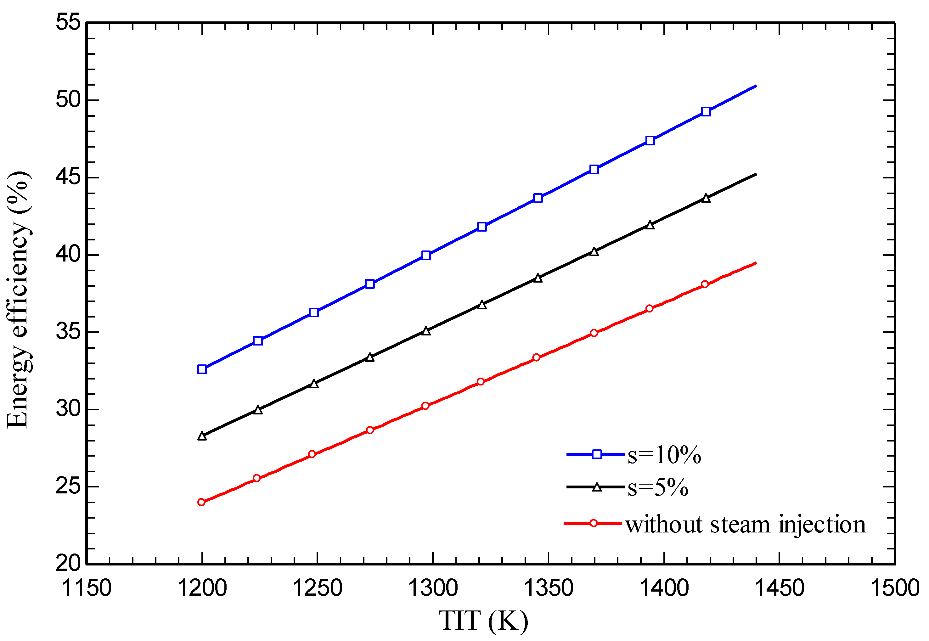
Figure 6.a demonstrates the impact on the system’s net power output of varying Pr1, which attains a maximal value at a specific value of Pr1 (around 5). As Pr1 increases, the power produced by the turbines increase. However, as Pr1 exceeds the optimal value, the system net power decreases because the power used by the compressor exceeds the power generated by the turbines.
Figure 6.
a. Effect on system net power output of variation of Pr1.
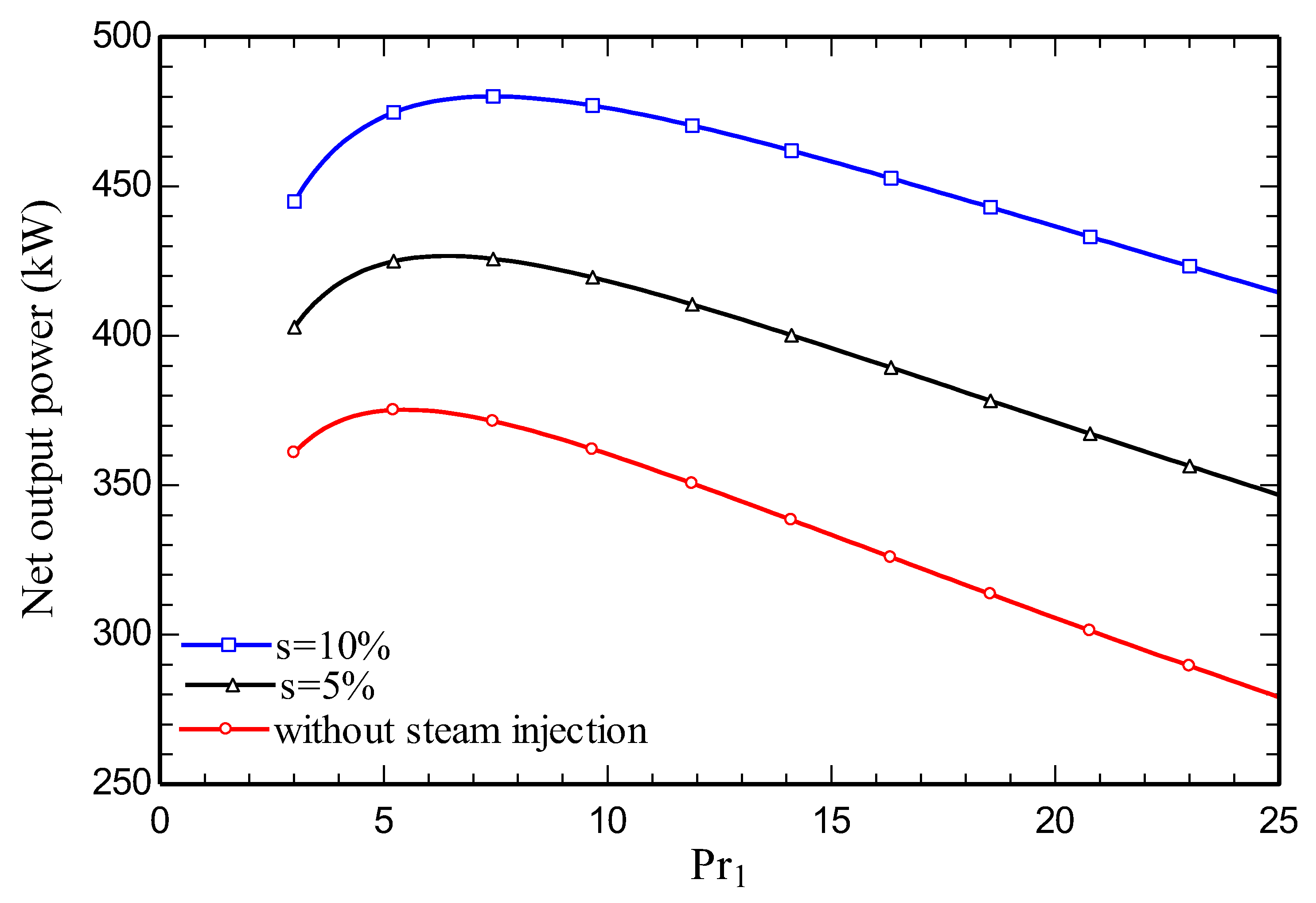
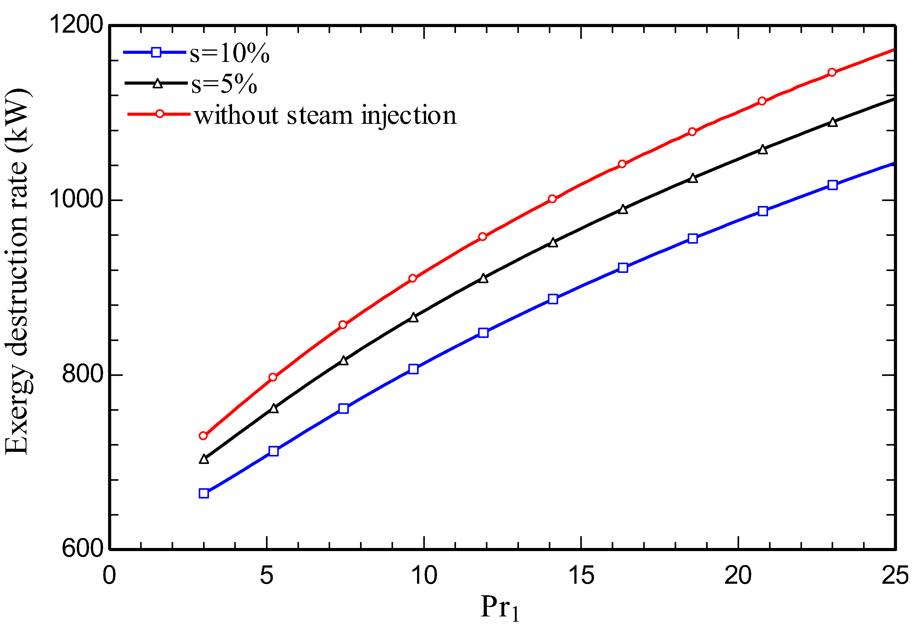
Figure 6.b presents for the system (including all components), the impact on the total exergy destruction rate of pressure ratio. With climbing pressure ratio, the exergy destruction rate is seen to rise. The system output work increases with pressure ratio, increasing the exergy destruction rate.
Figure 6.
b. Effect on system total exergy destruction rate of variation of Pr1.
The impact of varying pressure ratio on carbon dioxide emission index is seen in Figure 6.c. As depicted in Figure 6.a, the value of net output power first increases with Pr1 and then decreases and based on equation 51 the trend of carbon dioxide emission index is inverse to the net output power.
Figure 6.
c. Effect of variation of Pr1 on CO2 emission index of the system.
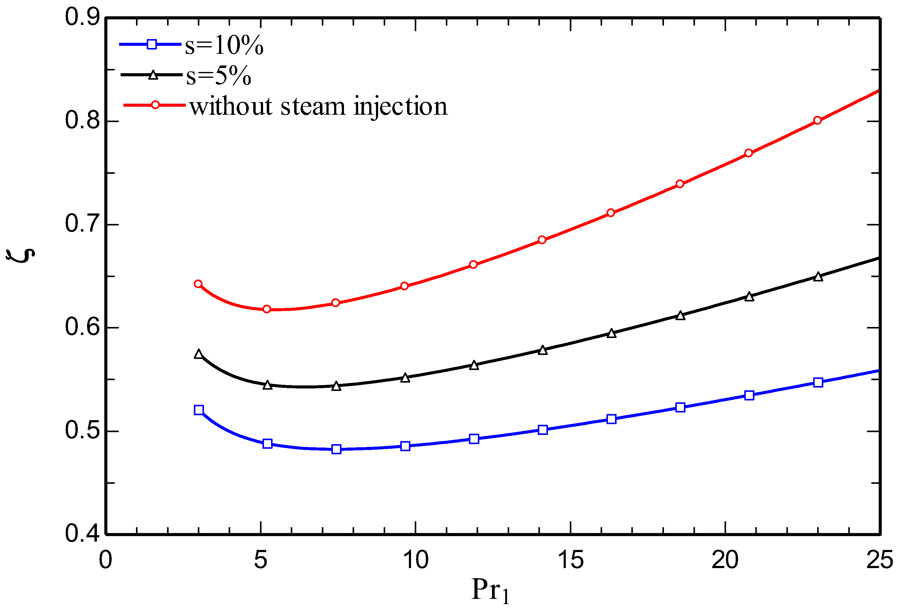
Figure 6.d and Figure 6.e show the respective impacts on system energy and exergy efficiencies of variations of Pr1. Meanwhile, the energy and exergy efficiencies are observed to increase then to decrease while decreasing the net output power (equations 41 and 49). Note that there is a straight relation between both energy and exergy efficiencies and net output power. Both efficiency trends are similar and have maximum points.
Figure 6.
d. Effect of variation of Pr1 on energy efficiency of the system.
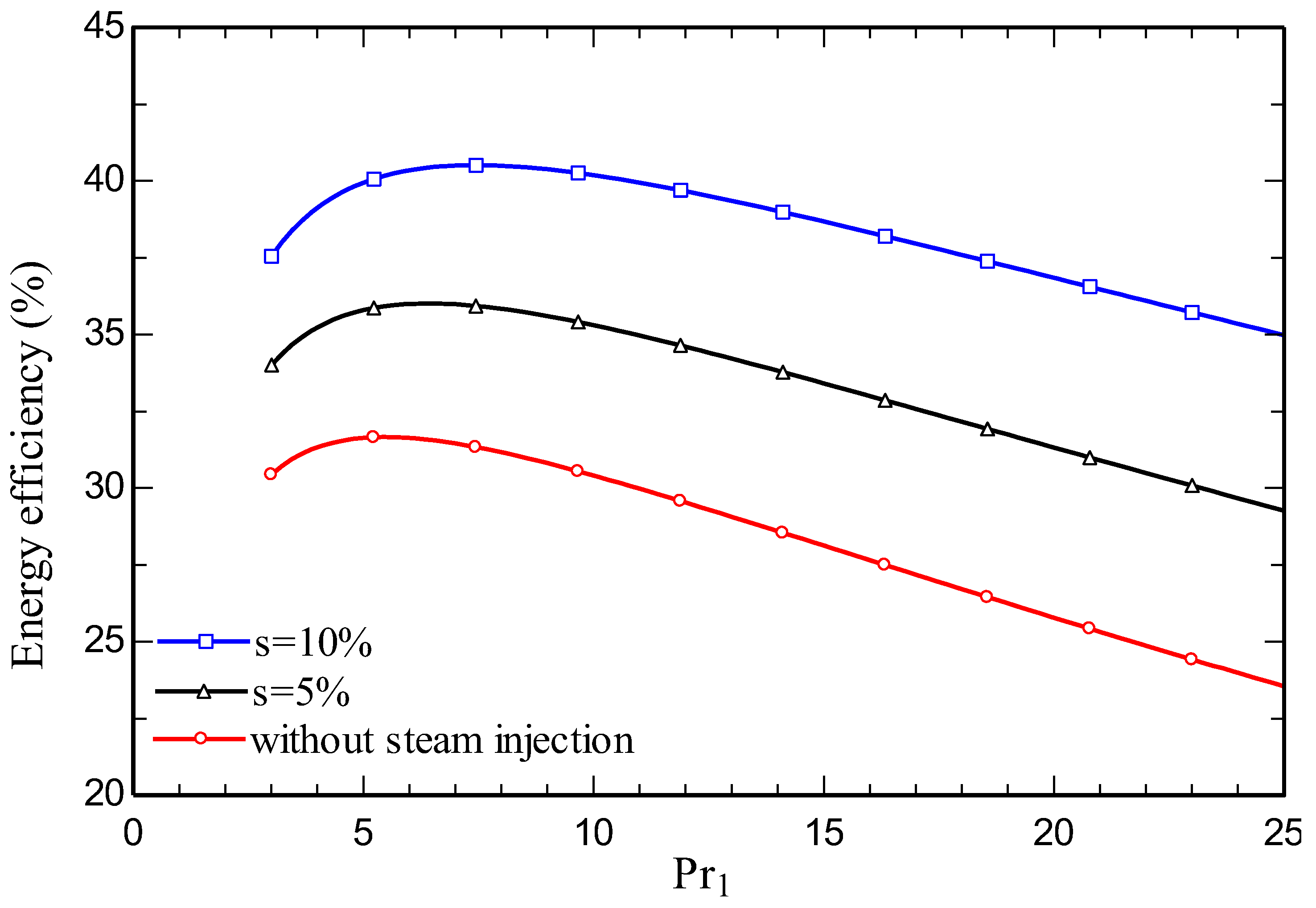
Figure 6.
e. Effect of variation of Pr1 on exergy efficiency of the system.
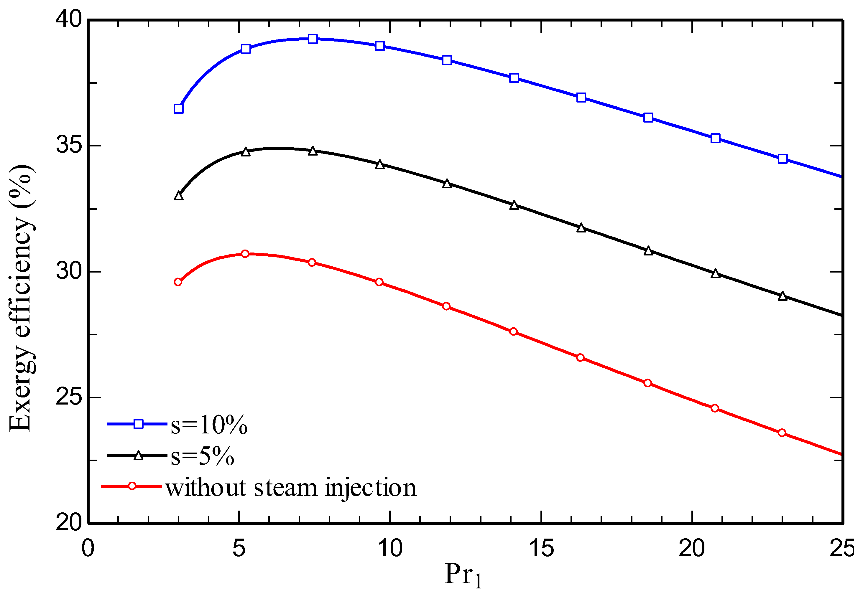
Figure 7 portrays how the system’s bottom cycle pressure ratio affects the net output power. As the bottom cycle’s pressure ratio rises, the net output power intensifies. The subsystem pressure ratio has a small impact on the main parameters in both cases examined, so further attention is not placed on the phenomenon. As the quantity of injected steam rises, the net output power improves.
Figure 7.
Effect of variation on system net output power of bottom cycle pressure ratio.

5. Conclusions
A combined cycle comprised of a gas turbine with two stages and steam injection coupled with a SCO2 subsystem cycle are investigated, considering energy and exergy aspects. Furthermore, in the case study and parametric study, the behaviors of both GTSC and SIGTSC systems are assessed separately. For both cycles, the combustion chamber was examined in-depth so that the modeling is more realistic.
The main findings of the research and the conclusions drawn from them follow:
- Increasing the amount of steam injection improves the system net output power and lowers the exergy destruction rate. Moreover, it reduces the carbon dioxide emission index.
- Steam injection in SIGTSC reduces the heat loss of the combustion chamber compared to the GTSC.
- Energy and exergy efficiencies of 35.3% and 34.1% respectively are obtained for the SIGTSC, which are greater than the corresponding values for the GTSC: 30.4% and 29.4%. Steam injection improves the thermodynamic efficiency.
- Due to this combustion chamber’s design temperature limitations for this configuration, TIT can only vary within a certain range. In addition, at 1440 K, the CC is considered almost adiabatic.
Nomenclature
| CC | Combustion chamber |
| Chemical flow exergy rate (kW) | |
| Outlet exergy flow rate (kW) | |
| Inlet exergy flow rate (kW) | |
| Standard chemical exergy of an ideal gas | |
| Thermodynamic flow exergy (kW) | |
| GTSC | Gas turbine with supercritical carbon dioxide |
| Molar Gibbs function (kJ/kmol) | |
| Enthalpy rate (kW) | |
| HEX | Heat exchange |
| HRSG | Heat recovery steam generator |
| HTR | High temperature recuperator |
| Internal irreversibility rate (kW) | |
| Equilibrium constant | |
| LHV | Lower heating value |
| LTR | Low temperature recuperator |
| Air mass flow rate (kg/s) | |
| P0 | Ambient pressure (kPa) |
| P1 | Compressor inlet pressure (kPa) |
| P10 | State 10 pressure (kPa) |
| Pexh | Exhaust pressure (kPa) |
| Pr1 | Air compressor pressure ratio |
| PRc | Bottom cycle pressure ratio |
| Heat transfer rate (kW) | |
| s | Steam injection ratio (%) |
| SCO2 | Supercritical carbon dioxide |
| SIGTSC | Steam injection gas turbine with supercritical carbon dioxide |
| STIG | Steam injection gas turbine |
| T0 | Ambient temperature (K) |
| T1 | Air compressor inlet temperature (K) |
| T10 | State 10 temperature (K) |
| Tfuel | Fuel temperature (K) |
| Product temperature (K) | |
| Ts | Steam temperature (K) |
| TIT | Turbine inlet temperature (K) |
| Production or consumption power (kW) | |
| WSR | Well-stirred reactor |
| x | Molar injection ratio of H2O to air |
| Molar fraction of species i in a mixture | |
| ε | Molar air-fuel ratio |
| ϕ | Equivalence ratio |
| Number of moles of combustion products | |
| ε HTR | Heat exchange efficiency for HTR (%) |
| ε LTR | Heat exchange efficiency for LTR (%) |
| η c,is | Air compressor isentropic efficiency (%) |
| η cc | Combustion chamber efficiency (%) |
| η t,is | Turbine isentropic efficiency (%) |
| η p,is | Pump isentropic efficiency (%) |
| η t, is, Bottom | Bottom cycle turbine isentropic efficiency (%) |
| η is, mc,rc | Bottom cycle compressor isentropic efficiency (%) |
| ηⅠ | Energy efficiency (%) |
| ηⅡ | Exergy efficiency (%) |
| Carbon dioxide emission index |
References
- Competitiveness of US Gas Turbine Manufacturers. Gas Turbine Assoc 2013. https://gasturbine.org/docs/newdocs/YAGTP4602_GTA White Paper_041013 final.pdf (accessed April 13, 2023).
- Jansohn P. Modern Gas Turbine Systems: High Efficiency, Low Emission, Fuel Flexible Power Generation. Elsevier Science; 2013.
- Kayadelen H, Ust Y. Performance and environment as objectives in multi-criterion optimization of steam injected gas turbine cycles. Appl Therm Eng 2014;71:184–196. [CrossRef]
- Lu M, Li D, Xie K, Sun G, Fu Z. Investigation of flame evolution and stability characteristics of H2-enriched natural gas fuel in an industrial gas turbine combustor. Fuel 2023;331:125938. [CrossRef]
- Ren J, Qian Z, Fei C, Lu D, Zou Y, Xu C, et al. Thermodynamic, exergoeconomic, and exergoenvironmental analysis of a combined cooling and power system for natural gas-biomass dual fuel gas turbine waste heat recovery. Energy 2023;269:126676. [CrossRef]
- Kayadelen H, Ust Y. Thermoenvironomic evaluation of simple, intercooled, STIG, and ISTIG cycles. Int J Energy Res 2018;42. [CrossRef]
- Kayadelen H, Ust Y, Başhan V. Thermodynamic performance analysis of state of the art gas turbine cycles with inter-stage turbine reheat and steam injection. Energy 2021;222:119981. [CrossRef]
- Yeranee K, Rao Y. A review of recent studies on rotating internal cooling for gas turbine blades. Chinese J Aeronaut 2021;34:85–113. [CrossRef]
- Javaherian A, Yari M, Gholamian E, Carton JG, Mehr AS. Proposal and comprehensive analysis of power and green hydrogen production using a novel integration of flame-assisted fuel cell system and Vanadium-Chlorine cycle: An application of multi-objective optimization. Energy Convers Manag 2023;277:116659. [CrossRef]
- Sinha AA, Saini G, Sanjay, Shukla AK, Ansari MZ, Dwivedi G, et al. A novel comparison of energy-exergy, and sustainability analysis for biomass-fueled solid oxide fuel cell integrated gas turbine hybrid configuration. Energy Convers Manag 2023;283:116923. [CrossRef]
- Ryu B, Duong PA, Kang H. Comparative analysis of the thermodynamic performances of solid oxide fuel cell–gas turbine integrated systems for marine vessels using ammonia and hydrogen as fuels. Int J Nav Archit Ocean Eng 2023:100524. [CrossRef]
- Bolland O, Stadaas J. Comparative Evaluation of Combined Cycles and Gas Turbine Systems With Water Injection, Steam Injection, and Recuperation. J Eng Gas Turbines Power-Transactions Asme - J ENG GAS TURB POWER-T ASME 1995;117. [CrossRef]
- Jonsson M, Yan J. Humidified gas turbines - A review of proposed and implemented cycles. Energy 2005;30:1013–78. [CrossRef]
- Roumeliotis I, Mathioudakis K. Evaluation of water injection effect on compressor and engine performance and operability. Appl Energy 2010;87:1207–16. [CrossRef]
- Eshati S, Abu A, Laskaridis P, Khan F. Influence of water–air ratio on the heat transfer and creep life of a high pressure gas turbine blade. Appl Therm Eng 2013;60:335–47. [CrossRef]
- Renzi M, Riolfi C, Baratieri M. Influence of the Syngas Feed on the Combustion Process and Performance of a Micro Gas Turbine with Steam Injection. Energy Procedia 2017;105:1665–70. [CrossRef]
- Mazzucco A, Rokni M. Thermo-economic analysis of a solid oxide fuel cell and steam injected gas turbine plant integrated with woodchips gasification. Energy 2014;76. [CrossRef]
- Amiri Rad E, Kazemiani P. Thermo-environmental and economic analyses of an integrated heat recovery steam-injected gas turbine. Energy 2017;141. [CrossRef]
- Salem Ahmed M, Mohamed Aly H. Performance characteristics of modified gas turbine cycles with steam injection after combustion exit. Int J Energy Res 2012;36. [CrossRef]
- Bahrami S, Ghaffari A, Thern M. Improving the Transient Performance of the Gas Turbine by Steam Injection during Frequency Dips. Energies 2013;6:5283–96. [CrossRef]
- Lei S, Wang D, Xie Y. Energy, Exergy and exergoeconomic analysis of two supercritical CO2 cycles for waste heat recovery of gas turbine. Appl Therm Eng 2021;196:117337. [CrossRef]
- Wu C, Wang S, Feng X, Li J. Energy, exergy and exergoeconomic analyses of a combined supercritical CO2 recompression Brayton/absorption refrigeration cycle. Energy Convers Manag 2017;148:360–77. [CrossRef]
- Akbari AD, Mahmoudi SMS. Thermoeconomic analysis & optimization of the combined supercritical CO2 (carbon dioxide) recompression Brayton/organic Rankine cycle. Energy 2014;78:501–12. [CrossRef]
- Lefebvre AH, Ballal DR. Gas Turbine Combustion: Alternative Fuels and Emissions, Third Edition. CRC Press; 2010.
- Kim Y, Kim CG, Favrat D. Transcritical or supercritical CO2 cycle using both low-and high-temperature heat sources. Energy 2012;43:402–15. [CrossRef]
- Kayadelen HK, Ust Y. Prediction of equilibrium products and thermodynamic properties in H2O injected combustion for CαHβOγNδ type fuels. Fuel 2013;113:389–401. [CrossRef]
- Kayadelen HK. A multi-featured model for estimation of thermodynamic properties, adiabatic flame temperature and equilibrium combustion products of fuels, fuel blends, surrogates and fuel additives. Energy 2018;143:241–56. [CrossRef]
- Poullikkas A. An overview of current and future sustainable gas turbine technologies. Renew Sustain Energy Rev 2005;9:409–43. [CrossRef]
- Moran MJ, Shapiro HN, Boettner DD, Bailey MB. Fundamentals of Engineering Thermodynamics, 9th Edition. Wiley; 2018.
- Bejan A, Tsatsaronis G, Moran MJ. Thermal Design and Optimization. Wiley; 1995.
- Wark K. Advanced Thermodynamics for Engineers. McGraw-Hill; 1995.
Figure 1.
Steam injection gas turbine with supercritical carbon dioxide (SIGTSC).
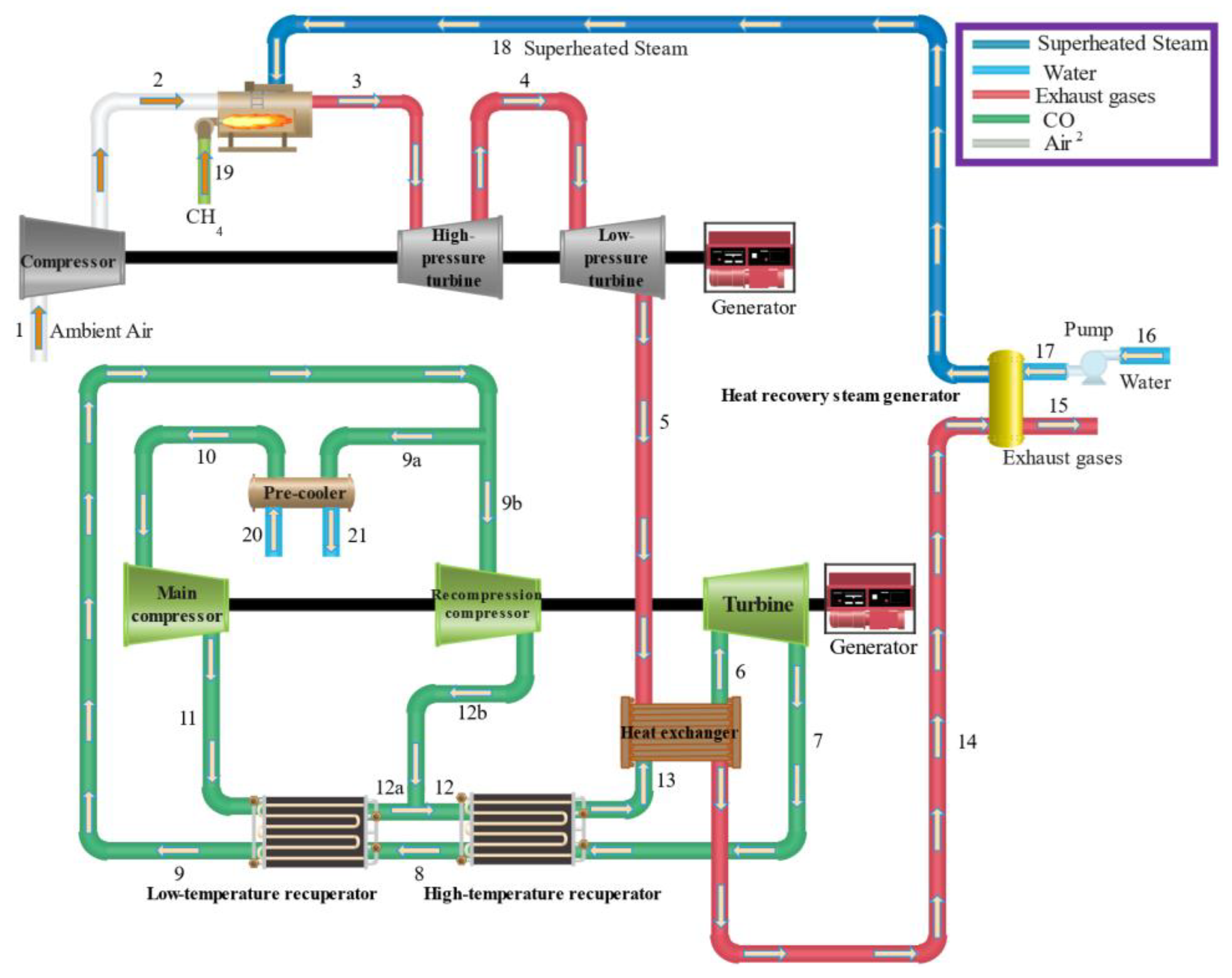
Figure 2.
Sankey diagram of SIGTSC.
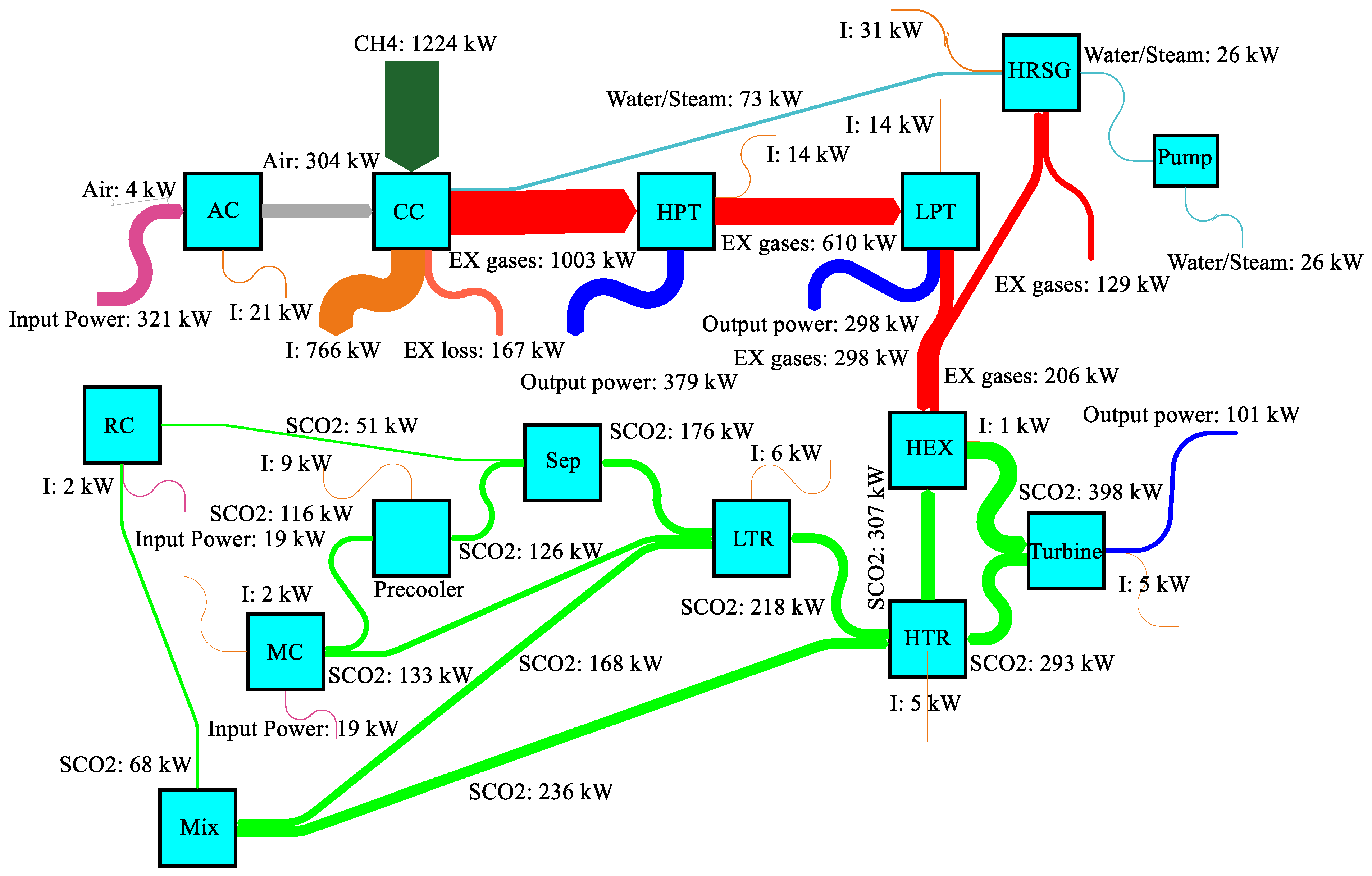
Figure 3.
a. Rate of generated electric power for components of both systems.
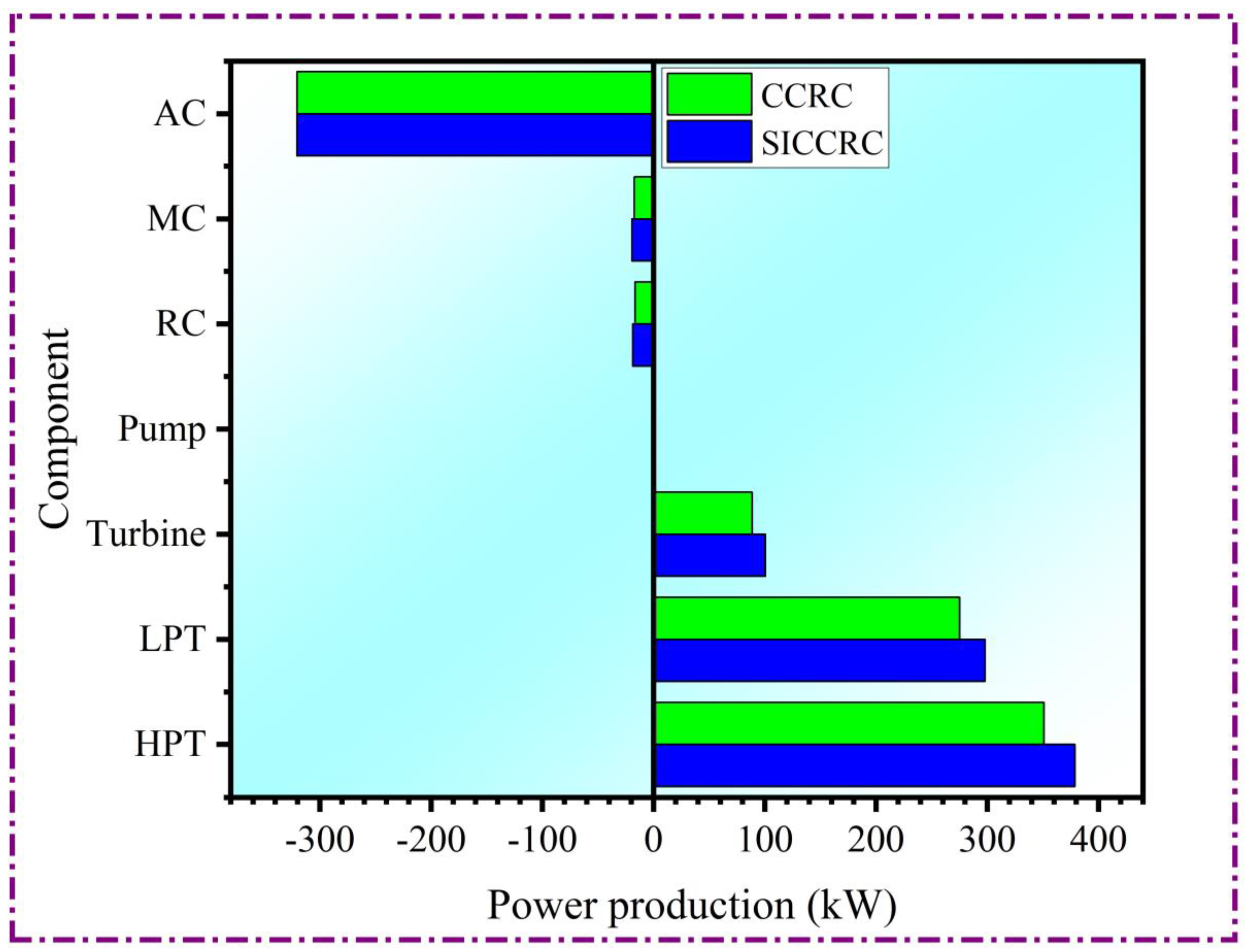
Table 2.
Energy rate balance relations for components of the power generation system.
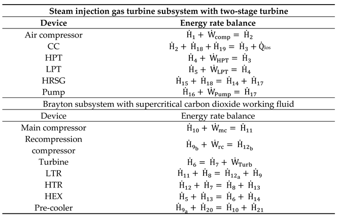
Table 3.
Exergy rate balance relations for components of the power generation system.
| Steam injection gas turbine subsystem with two-stage turbine | |
|---|---|
| Component | Exergy rate balance |
| Air compressor | |
| CC | |
| HPT | |
| LPT | |
| HRSG | |
| Pump | |
| Brayton subsystem with supercritical carbon dioxide working fluid | |
| Component | Exergy rate balance |
| Main compressor | |
| Recompression compressor | |
| Turbine | |
| LTR | |
| HTR | |
| HEX | |
| Pre-cooler | |
Table 4.
Comparison of molar fractions of combustion products from current study with reference [26].
Table 4.
Comparison of molar fractions of combustion products from current study with reference [26].
| Combustion product | Molar fraction obtained in current study with φ=0.6 | Molar percentage in reference [26] with φ=0.6 | Molar fraction obtained in current study with φ=1.2 | Molar percentage in reference [26] with φ=1.2 |
|---|---|---|---|---|
| CO2 | 0.05148 | 0.05151 | 0.0630 | 0.0631 |
| H2O | 0.2343 | 0.2338 | 0.2789 | 0.2786 |
| N2 | 0.6451 | 0.6455 | 0.5944 | 0.5948 |
| O2 | 0.06821 | 0.06824 | 4.12 E-06 | 1.42E-07 |
| CO | 1.76 E-06 | 3.22E-07 | 0.0317 | 0.0316 |
| H2 | 2.9 E-06 | 5.34E-07 | 0.0314 | 0.0315 |
| H | 4.927E-08 | 3.84E-09 | 2.37 E-04 | 4.35E-05 |
| O | 1.84 E-06 | 3.36E-07 | 1.08 E-06 | 3.69E-08 |
| OH | 1.52 E-04 | 5.46E-05 | 2.25 E-04 | 3.62E-05 |
| NO | 7.70 E-04 | 8.35E-04 | 2.71 E-05 | 5.39E-06 |
Table 5.
Validation results obtained in the present work and Ref [22].
Table 5.
Validation results obtained in the present work and Ref [22].
| State no. | Present work temperature [°C] |
Ref. [22] temperature [°C] |
Present work pressure [kPa] |
Ref. [22] pressure [kPa] |
Present work mass flow rate [kg/s] | Ref. [22] mass flow rate [kg/s] |
Present work exergy rate [MW] |
Ref. [22] exergy rate [MW] |
|
|---|---|---|---|---|---|---|---|---|---|
| 6 | 550 | 550 | 207.2 | 207.2 | 2939 | 2938.18 | 1557 | 1556.5 | |
| 7 | 428 | 428.01 | 74 | 74 | 2939 | 2938.18 | 1145 | 1144.5 | |
| 8 | 257.6 | 257.48 | 74 | 74 | 2939 | 2938.18 | 851.83 | 851.29 | |
| 9 | 119.5 | 119.36 | 74 | 74 | 2939 | 2938.18 | 690.45 | 690.05 | |
| 10 | 32 | 32 | 74 | 74 | 2098 | 2096.18 | 453.08 | 452.68 | |
| 11 | 97.03 | 96.88 | 207.2 | 207.2 | 2098 | 2096.18 | 520.13 | 519.55 | |
| 12 | 229.9 | 229.72 | 207.2 | 207.2 | 2939 | 2938.18 | 924.24 | 923.60 | |
| 13 | 384.4 | 384.36 | 207.2 | 207.2 | 2939 | 2938.18 | 1200 | 1199.13 | |
Table 6.
Thermodynamic properties of states of the GTSC power generation system.
| State no. | Temperature [K] |
Pressure [kPa] |
Molar enthalpy [kJ/kmol] |
Molar entropy [kJ/kmol-K] |
Mass flow rate [kg/s] | Exergy rate [kW] |
|---|---|---|---|---|---|---|
| 1 | 298.2 | 101.3 | 0 | 198.6 | 1 | 4.473 |
| 2 | 608.7 | 1013 | 9246 | 200.6 | 1 | 303.9 |
| 3 | 1300 | 1013 | -2423 | 228.7 | 1.023 | 912.9 |
| 4 | 1026 | 320.4 | -12138 | 229.9 | 1.023 | 549.1 |
| 5 | 800.6 | 101.3 | -19755 | 231.1 | 1.023 | 261.1 |
| 6 | 823.2 | 20720 | 23230 | -0.241 | 0.01503 | 350.5 |
| 7 | 701.2 | 7400 | 17340 | 0.701 | 0.01503 | 257.8 |
| 8 | 530.8 | 7400 | 8789 | -13.26 | 0.01503 | 191.8 |
| 9 | 392.7 | 7400 | 1849 | -28.43 | 0.01503 | 155.4 |
| 10 | 305.2 | 7400 | -5628 | -50.71 | 0.01073 | 102 |
| 11 | 370.2 | 20720 | -4028 | -50.06 | 0.01073 | 117.1 |
| 12 | 503 | 20720 | 5695 | -27.27 | 0.01503 | 208.1 |
| 13 | 657.6 | 20720 | 14246 | -12.42 | 0.01503 | 270.1 |
| 14 | 686.2 | 101.3 | -23494 | 226.1 | 1.023 | 180.3 |
| 15 | 298.2 | 1013 | -74595 | 167.1 | 0.02346 | 1225 |
| 16 | 298.2 | 101.3 | 1889 | 6.61 | 0.1065 | 0 |
| 17 | 308.2 | 101.3 | 2642 | 9.096 | 0.1065 | 1.316 |
Table 7.
Thermodynamic properties of states of the SIGTSC power generation system.
| State no. | Temperature [K] |
Pressure [kPa] |
Molar enthalpy [kJ/kmol] |
Molar entropy [kJ/kmol-K] |
Mass flow rate [kg/s] |
Exergy rate [kW] |
|---|---|---|---|---|---|---|
| 1 | 298.2 | 101.3 | 0 | 198.6 | 1 | 4.473 |
| 2 | 608.7 | 1013 | 9246 | 200.6 | 1 | 303.9 |
| 3 | 1300 | 1013 | -16709 | 229.7 | 1.073 | 1003 |
| 4 | 1029 | 320.4 | -26443 | 230.9 | 1.073 | 610.1 |
| 5 | 806.4 | 101.3 | -34104 | 232.1 | 1.073 | 298.2 |
| 6 | 823.2 | 20720 | 23230 | -0.241 | 0.01706 | 397.8 |
| 7 | 701.2 | 7400 | 17340 | 0.701 | 0.01706 | 292.5 |
| 8 | 530.8 | 7400 | 8789 | -13.26 | 0.01706 | 217.6 |
| 9 | 392.7 | 7400 | 1849 | -28.43 | 0.01706 | 176.4 |
| 10 | 305.2 | 7400 | -5628 | -50.71 | 0.01218 | 115.7 |
| 11 | 370.2 | 20720 | -4028 | -50.06 | 0.01218 | 132.9 |
| 12 | 503 | 20720 | 5695 | -27.27 | 0.01706 | 236.1 |
| 13 | 657.6 | 20720 | 14246 | -12.42 | 0.01706 | 306.5 |
| 14 | 687.3 | 101.3 | -38044 | 226.8 | 1.073 | 206.3 |
| 15 | 569.7 | 101.3 | -41829 | 220.8 | 1.073 | 129.1 |
| 16 | 298.2 | 101.3 | 1889 | 6.61 | 0.05 | 26.37 |
| 17 | 298.2 | 1013 | 1912 | 6.606 | 0.05 | 26.41 |
| 18 | 573.2 | 1013 | 54951 | 128.2 | 0.05 | 73.03 |
| 19 | 298.2 | 1013 | -74595 | 167.1 | 0.02345 | 1224 |
| 20 | 298.2 | 101.3 | 1889 | 6.61 | 0.1208 | 0 |
| 21 | 308.2 | 101.3 | 2642 | 9.096 | 0.1208 | 1.494 |
Table 8.
Thermodynamic performance in terms of efficiencies.
| Subsystem | Energy efficiency (%) |
Exergy efficiency (%) |
|---|---|---|
| GTSC system | ||
| STIG | 25.78 | 24.95 |
| SCO2 | 40.59 | 67.86 |
| Total | 30.41 | 29.43 |
| SIGTSC system | ||
| SISTIG | 30.06 | 29.09 |
| SCO2 | 40.59 | 67.65 |
| Total | 35.31 | 34.17 |
Disclaimer/Publisher’s Note: The statements, opinions and data contained in all publications are solely those of the individual author(s) and contributor(s) and not of MDPI and/or the editor(s). MDPI and/or the editor(s) disclaim responsibility for any injury to people or property resulting from any ideas, methods, instructions or products referred to in the content. |
© 2023 by the authors. Licensee MDPI, Basel, Switzerland. This article is an open access article distributed under the terms and conditions of the Creative Commons Attribution (CC BY) license (http://creativecommons.org/licenses/by/4.0/).
Copyright: This open access article is published under a Creative Commons CC BY 4.0 license, which permit the free download, distribution, and reuse, provided that the author and preprint are cited in any reuse.


