
Submitted:
24 July 2023
Posted:
08 August 2023
You are already at the latest version
Abstract
Numerical optimization methods are widely used for designing turbomachinery components due to the cost and time savings they can provide. In the available literature, shape optimization of radial compressors is mainly focused on improving the impeller alone. However, it is a well-established knowledge that the volute plays a key role in the overall performance of the compressor. The aim of the present paper is to perform the adjoint-based optimization of a volute that is designed for the SRV2-O compressor. The CAD model is first created, using a parametrization of 33 design parameters. Then, a butterfly topology is applied to mesh the computational domain with a multi-block structured grid, and an elliptic smoothing procedure is then used to improve the quality of the fluid grid. A steady-state RANS CFD solver with Spalart-Allmaras turbulence model is used to solve the Navier-Stokes equations, and flow sensitivities are computed with an adjoint solver. The objective function consists in minimizing the loss coefficient of the volute. The optimization is performed to obtain an improved design with 14% losses reduction. Detailed flow and design analysis is carried out to highlight the loss reduction mechanisms followed by the optimizer. Finally, the compressor map of the full stage is compared between the baseline and the optimized volute through CFD simulations using a mixing plane interface. This research demonstrates the successful use of a gradient-based optimization technique to improve the volute of a radial compressor and opens the door towards optimizing simultaneously the wheel and the volute.
Keywords:
Turbomachinery
; Design optimization
; Adjoint methods
; Radial compressor
; Volute
1. Introduction
Design optimization of turbomachinery components through numerical computations has-been an increasing engineering activity for the past decades, which has gone hand in hand with improvements in computational power and optimization algorithms. Nowadays, designers must deal with problems of high complexity, involving geometries with many design variables while aiming to achieve highly efficient designs with better performance. Within this context, two major approaches can be distinguished, which are gradient-free and gradient-based optimization methods. The first one offers the advantage of converging to the global best geometry since the entire design space is investigated, however this comes at the cost of a large number of costly Computational Fluid Dynamics (CFD) simulations. On the other hand, the gradient-based approach allows converging to a local optimum within a few iterations only, where the computational cost is driven by the gradient calculation method.
One of many engineering fields where design optimization can be applied is the development of highly efficient radial compressors. However, the optimization is generally conducted only on the impeller, while one or several volutes are designed around the optimized wheel to offer best performance at design flow condition. Kim et al. followed such a design optimization process on a centrifugal pump [1]. Once the impeller was optimized, two suitable volute geometries with different cross-sectional shapes were designed by applying Stepanoff’s theory [2]. The candidates performance were then numerically assessed through CFD computations for selecting the best cross-section of the two. Based on that, four new designs with various circumferential cross-section distributions were also evaluated in order to come up with the final optimized design. Similarly, Han et al. [3] performed the optimization of the centrifugal pump impeller using a genetic algorithm and a back propagation neural network, while the volute shape was manually improved afterwards. To do so, four geometrical parameters were used to define the geometry. It was shown that the optimized geometry offers better hydraulic performance at various flow conditions. Ji et al. [4] performed the 3D numerical analysis of a radial compressor and proposed to manually apply geometrical modifications to the volute in order to improve the overall polytropic efficiency.
Another possibility is the design optimization of the volute alone using an optimization algorithm, while imposing constant flow conditions at the inlet. By using this strategy, Huang et al. [5] optimized a volute with rectangular cross-section for a radial compressor, with the objective of maximizing the minimal volute static pressure recovery coefficient at three flow conditions. Seven design parameters were chosen to define the shape and circumferential distribution of the cross-section, and a constrained optimization using response surfaces (CORS) method was used to update these parameters. The whole compressor flow with impeller and optimized volute was computed to assess the performance. It was shown that the optimal volute offered a higher static pressure recovery coefficient, and that the compressor overall efficiency was slightly improved. Likewise, it is possible to include the predefined (possibly optimized) impeller geometry into the CFD computations all along the optimization process of the volute. Such a procedure was applied by [6] to optimize a circular volute cross-section defined by seven design parameters. In total, 1500 individuals had to be evaluated during the gradient-free optimization process. In the end, the optimized volute offered a better operating range and an increased total pressure ratio as well as isentropic efficiency.
To the authors best knowledge, no gradient-based optimization of a volute was performed to this date, although the use of such methods allows to increase the number of degrees of freedom (33 design variables in the present case) at a limited computational cost. This will prove to be very useful when the wheel and volute will be simultaneously optimized, as the increased number of design variables in such case can only be tackled effectively through a gradient-based approach. The present work has to be seen as a precursor for achieving this goal. The paper is organized as follows: first the volute application is introduced, with focus on the parametrization and the numerical framework. The volute optimization method and results are then presented. Finally, a comparison of the compressor maps with and without optimized design shows the improvement in total-to-total efficiency for the whole compressor.
2. Srv2 Compressor with Volute
The SRV2 compressor wheel is a well-known open test case in the turbomachinery committee [7]. It has been the subject of several optimization works, see for instance [8]. An increase of 3.9% of total-to-total efficiency was obtained within 16 iterations of a gradient-based optimizer, using 44 design variables to parametrize the impeller geometry. In the present work, a baseline volute geometry has been created such that it is adapted to the SRV2 impeller.
2.1. Geometry Definition
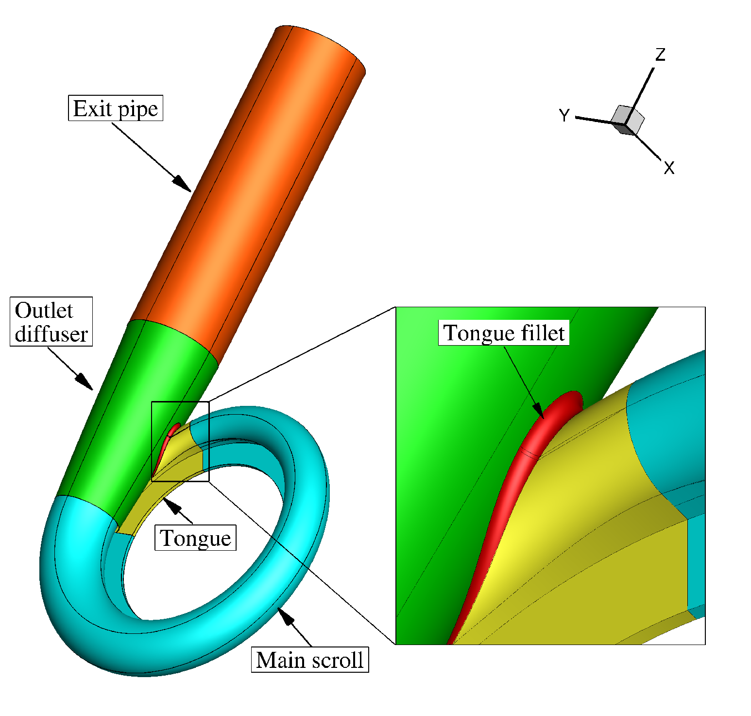
To build a volute geometry for the SRV2 compressor, two-dimensional profiles are first constructed, as shown in Figure 1a. Each profile is characterized by its inlet radius () and inlet height () which remain unchanged during the optimization as they are imposed by the impeller outlet geometry. Other design parameters include the height of the wall located above the inlet diffuser (), its radius location () the radius of the fillet between this wall and the low left arc (), and the radius of the fillet located between the same wall and the inlet diffuser (). One should note that during the optimization, the wall radius can only decrease, such that the overall size of the volute is limited. The circular shape is built with a series of arcs, of which the local radius () is equal to the minimum volute radius (), representative of the throat section of the volute, multiplied by a local radius ratio that depends on the azimuthal position. Once created, the profiles are distributed along the circumference, as shown in Figure 1b, and then interpolated into a surface skin. The radius ratio at a given azimuthal position is given by a distribution law that is defined through a Bézier curve with 8 control points. As presented in Figure 2, the Y coordinates of these control points are used as design variables in the optimization. The tongue is created with the same logic as in the main scroll case, with profiles located at different azimuthal positions and then interpolated into a surface skin. An axial outlet diffuser is added at the end of the scroll. It is made of circular sections of which the local radius and center position depend on the axial location along the exit axis (Z direction), such as depicted in Figure 3. These characteristics are determined by means of two Bézier curves with 11 control points each. A fillet is created between the tongue and the outlet diffuser. Its radius is used as design variable in the optimization as it will dictate whether a rounded tongue or a sharp tongue is better for the flow performance. Finally, a circular pipe of constant diameter is extruded at the end of the outlet diffuser. This diameter cannot be modified during the optimization, to allow connectivity to a pipe of standard diameter. The outlet diffuser and exit pipe are also characterized by their length, which are set to 32 and 56 centimeters respectively and remain constant during the optimization. The 3D geometry is presented in Figure 4, with a close-up view on the tongue fillet. In total, 33 design variables are used during the optimization process.
Figure 1.
Scroll and tongue geometry definition.
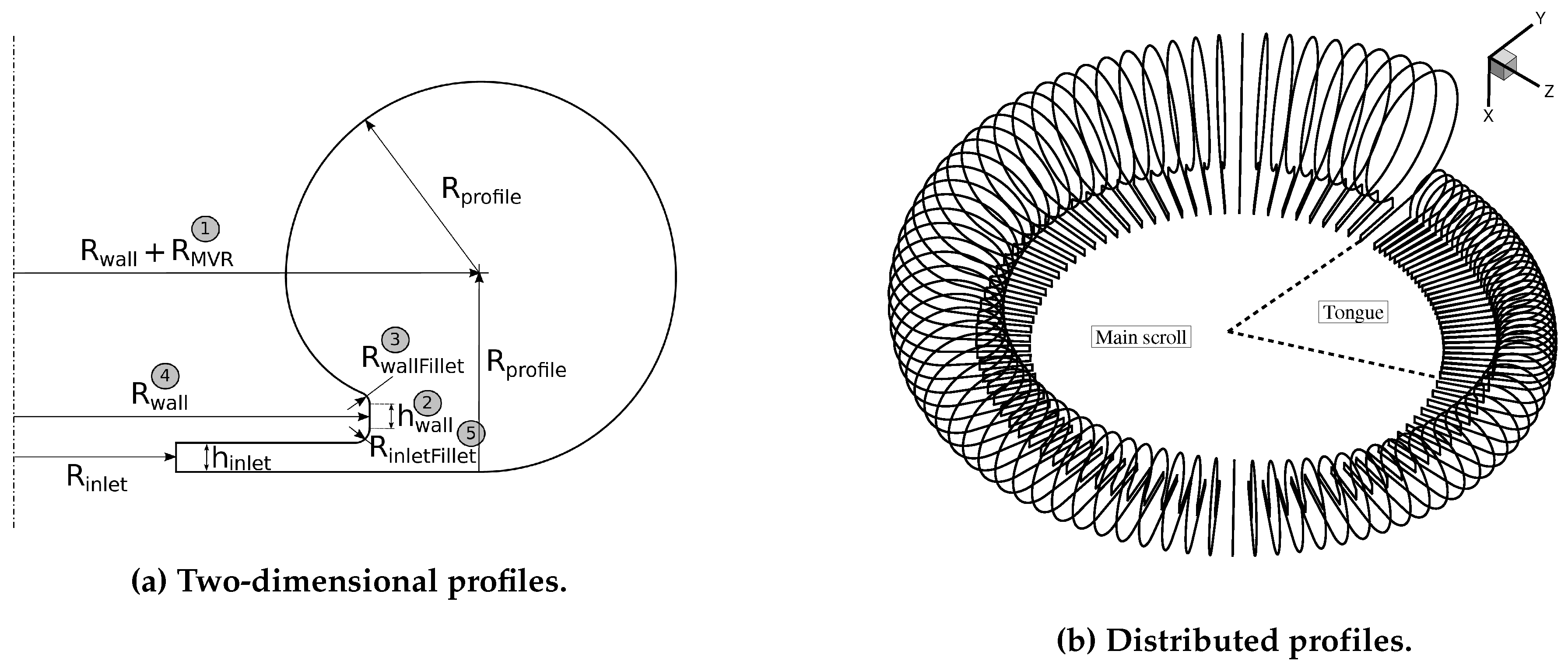
Figure 2.
Radius ratio distribution law based on a Bézier curve.
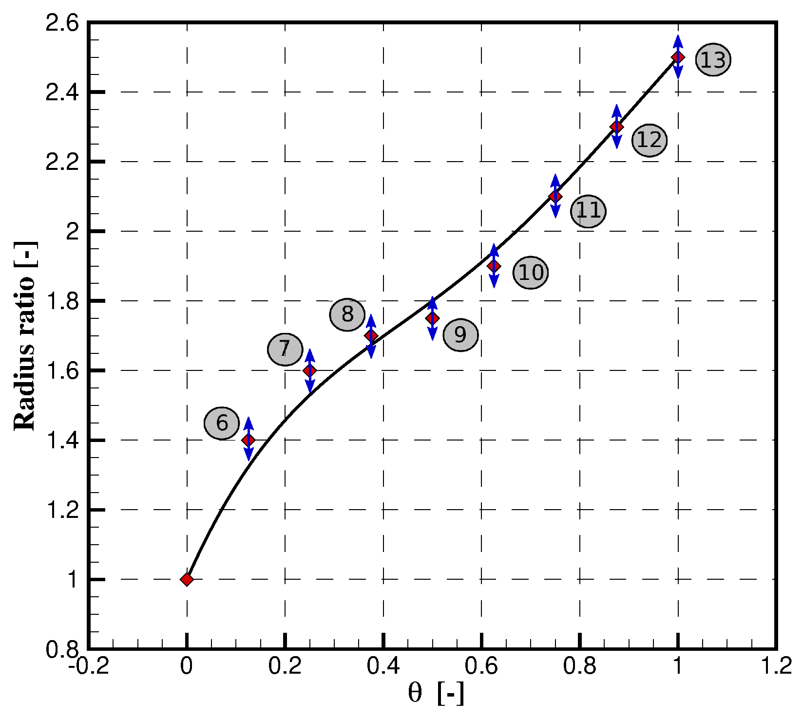
Figure 3.
Outlet diffuser profiles.
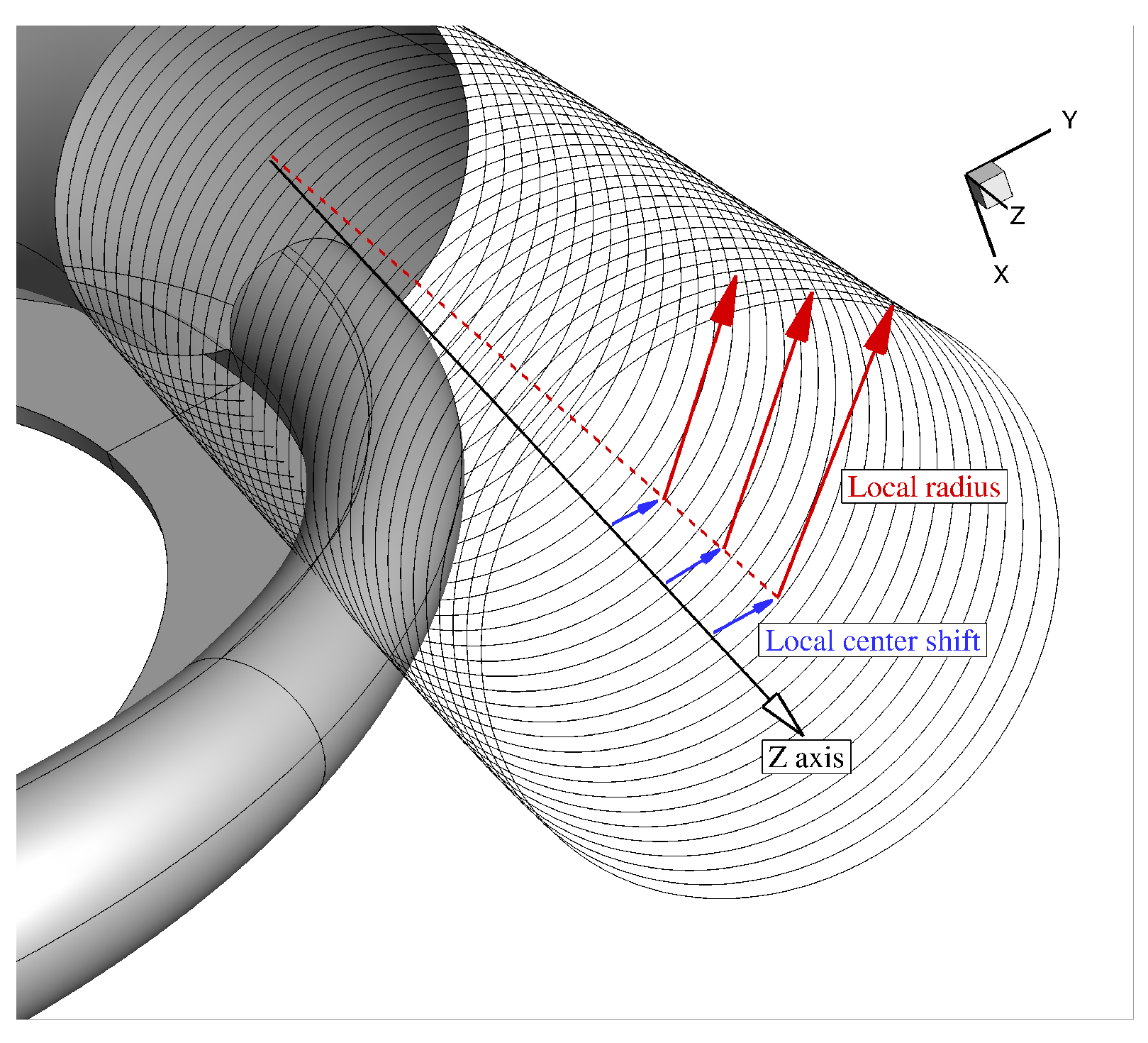
Figure 4.
3D volute geometry.
2.2. Numerical Framework
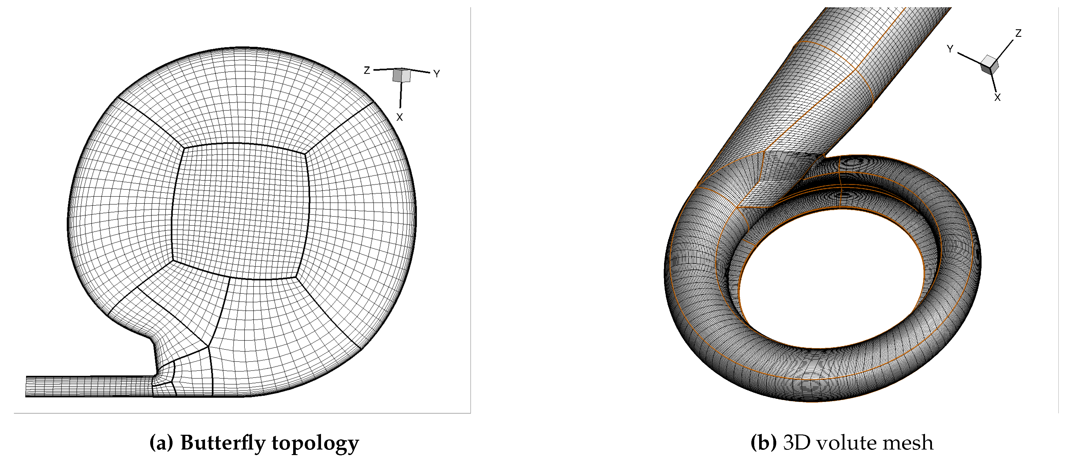
A multi-block structured grid with butterfly topology is used to mesh the computational domain. The initial grid is generated with transfinite interpolation [9] and the mesh quality is then improved by an in-house 3D elliptic grid smoothing [10], using a Gauss-Seidel method. The topology and final mesh can be visualized in Figure 5a and Figure 5b respectively. The mesh size is 3.1M cells, which has been selected based on a mesh convergence study. This choice is taken as a good compromise between computational effort and accuracy. The numerical flow computations are performed by means of an in-house RANS solver with Spalart-Allmaras turbulence model, which have been validated against experimental data in the past and is extensively detailed in [11]. The total quantities and flow angle are imposed at the inlet of the domain, while the static pressure is set as constant at the outlet. In average, the Y-Plus value is comprised between 2 and 5.
Figure 5.
Fluid grid.
2.3. Preliminary Setup for the Optimization
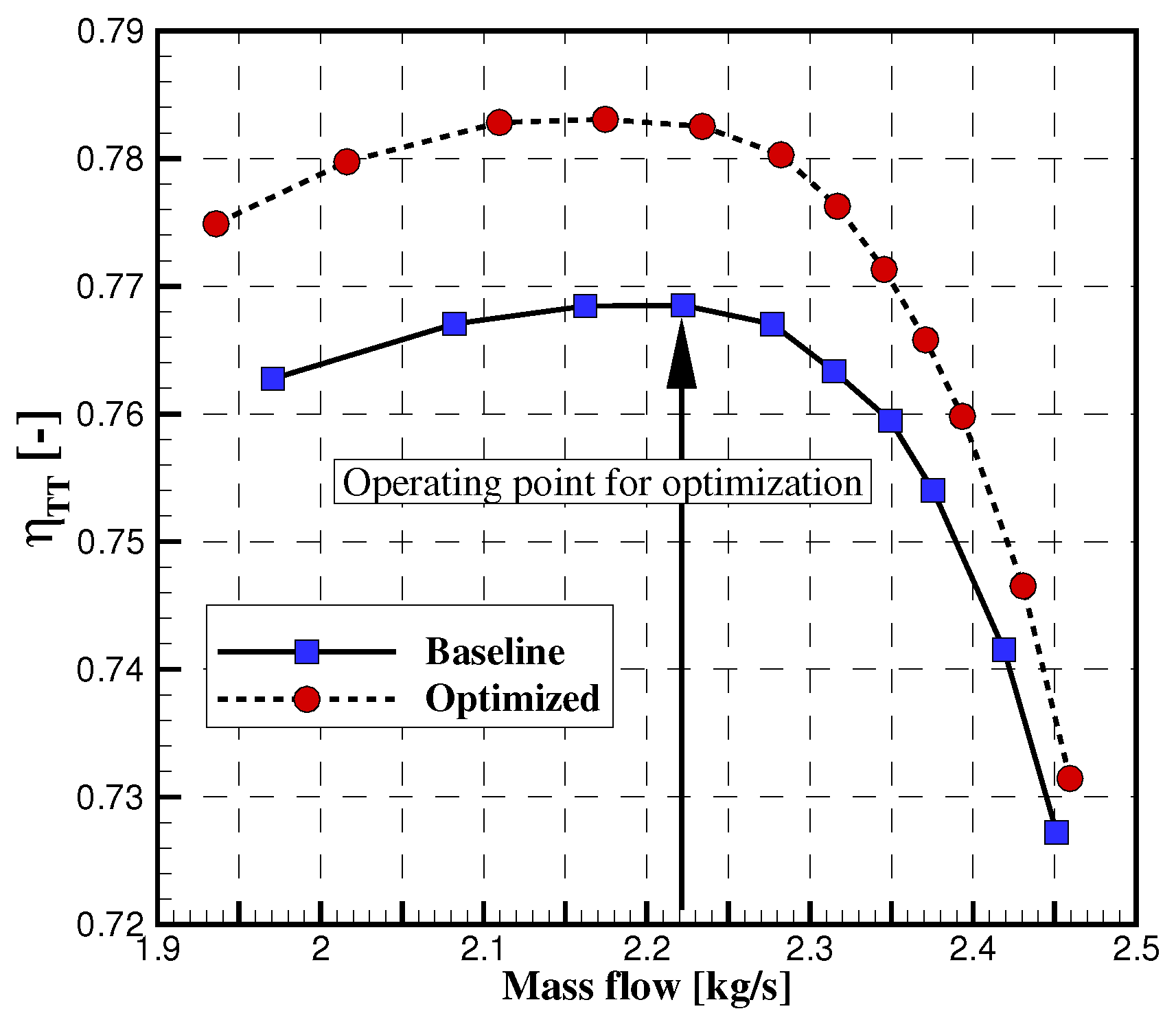
The optimization is conducted at peak efficiency of the SRV2-O compressor. To find this operating point, first the performance map is obtained by running several CFD simulations on the full stage (wheel + volute). For details on the impeller mesh, the reader is referred to [8]. A mixing-plane interface is used to connect the two components, following the approach suggested by Wang [12] where a set of one-dimensional control volumes (in rotor spanwise direction) is used to update the circumferentially averaged states at the interface. The states in these control volumes are used to set inlet and outlet conditions for the volute and rotor respectively, using Giles’s quasi-2D non-reflective boundary condition considering the propagation of characteristic quantities, which neglects local viscosity [13]. The states in the one-dimensional control volumes are added as unknowns to the system of equations, to facilitate a completely implicit formulation of the mixing-plane. The static pressure at the outlet of the volute is modified for each calculation in order to vary the mass flow in the compressor. The results are found in Figures 14 and 15, where the total-to-total pressure ratio and total-to-total efficiency are presented for the baseline and optimized designs. At this point, one should only pay attention to the curves related to the baseline. The point of peak-efficiency corresponds to a mass flow of 2.22 kg/s in the baseline compressor, which is obtained by setting an outlet static pressure of 310000 Pa. The flow data are extracted at the exit of the impeller and used as inflow conditions at the inlet of the volute during the optimization. The boundary conditions are summarized in Table 1. The inlet flow angle is specified relative to the normal of the inlet face (radial direction). The rotational speed is 40000 RPM.

Table 1.
BOUNDARY CONDITIONS.
| Inlet flow angle | [] | 50 | |
| Inlet total pressure | [Pa] | 343000 | |
| Inlet total temperature | [K] | 453 | |
| Outlet static pressure | [Pa] | 310000 |
VOLUTE OPTIMIZATION
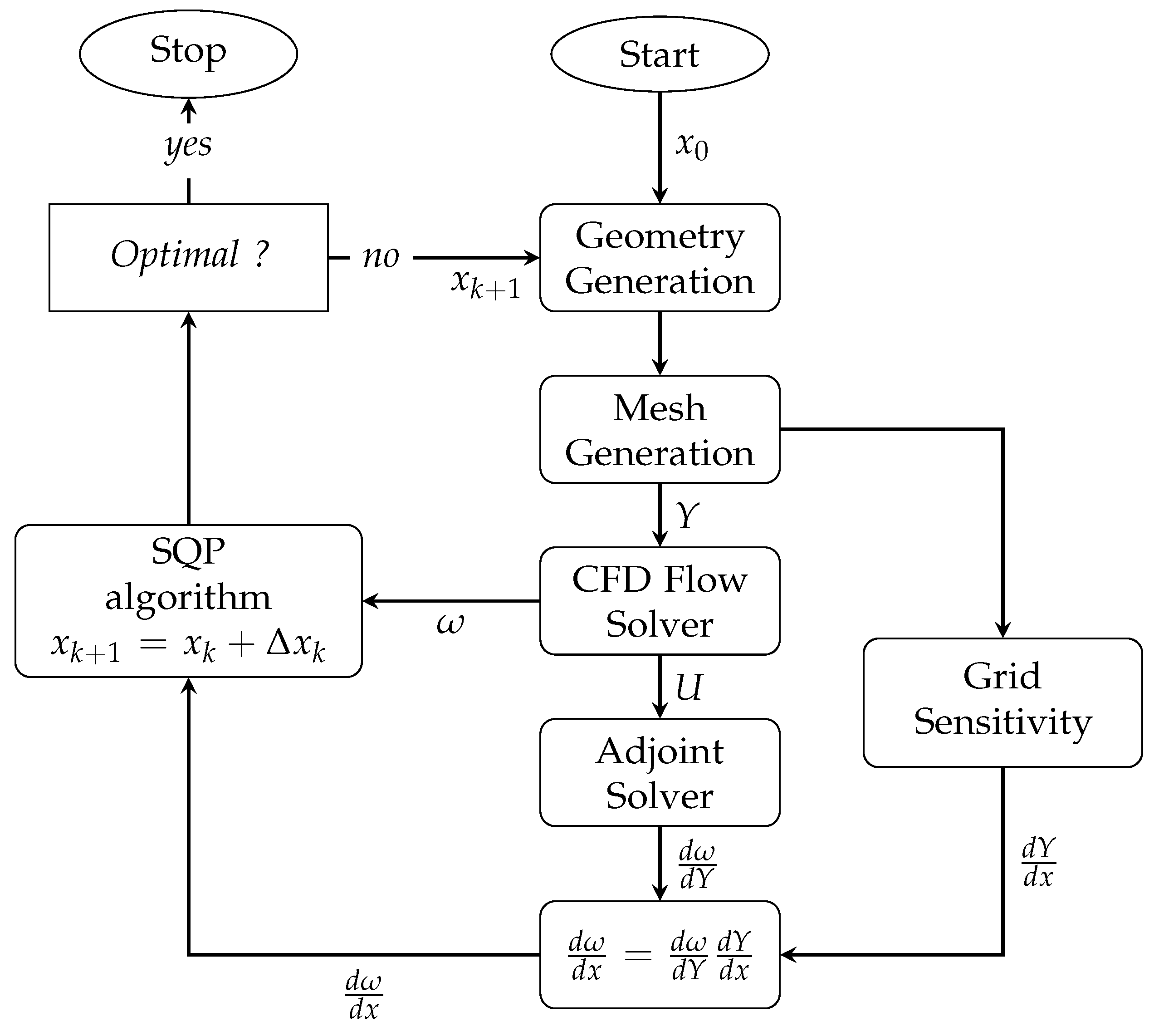
In this section, the gradient-based optimization of the volute is presented. The optimization loop that is used within this work is shown in Figure 6. Starting from a baseline design defined by initial parameters , the volute geometry is created, meshed and CFD calculations are run. The gradients evaluation of the objective function with respect to the grid points position () is performed by means of a discrete adjoint solver [11]. In parallel, grid sensitivities () with respect to the design variables are computed using a complex step method [14]. The chain rule is then applied to obtain the gradient of the performance quantities of interest with respect to the design variables (). This information is provided to a SQP optimizer [15] that updates the design variables. The process is repeated until an optimal solution is found. The accuracy of the gradients calculation method has been proved in previous studies ([8,11,15]).
Figure 6.
Gradient-based design optimization loop implemented within the CADO software.
2.4. Objective Definition
The objective is to minimize the loss coefficient of the volute, which is defined in Equation (1) where total pressure quantities are mass-averaged and the inlet static pressure is area-averaged. It is important to stress the fact that minimizing the loss coefficient with constant outlet static pressure will inevitably change the mass flow, which is likely to increase in order to reduce the head losses. Nevertheless, the loss minimization still holds if the initial mass flow is recovered. Furthermore, it was shown by [16] that for a given design, the loss coefficient depends exclusively on the inlet flow angle, while it is independent from the mass flow. This can be attributed to a negligible change in Reynolds and Mach number, hence keeping the non-dimensional similitude quasi-intact.
2.5. Optimization Results
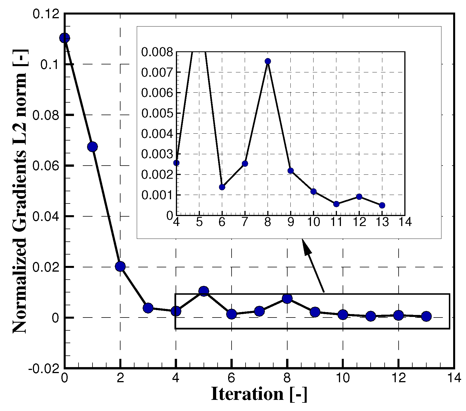
The optimization history is presented in Figure 7. A reduction of 14% in loss coefficient is achieved within 13 major iterations, over which 17 CFD evaluations and 13 adjoint calculations are required. The data are normalized by the baseline performance, for which the absolute loss coefficient is equal to 0.347. During the optimization process, the L2 norm of the gradients is reduced by two orders of magnitude as shown in Figure 8. At the final iterate, the L2 norm is relatively close to zero, suggesting that the optimizer has found an optimal solution to the optimization problem.
Figure 7.
Optimization history.
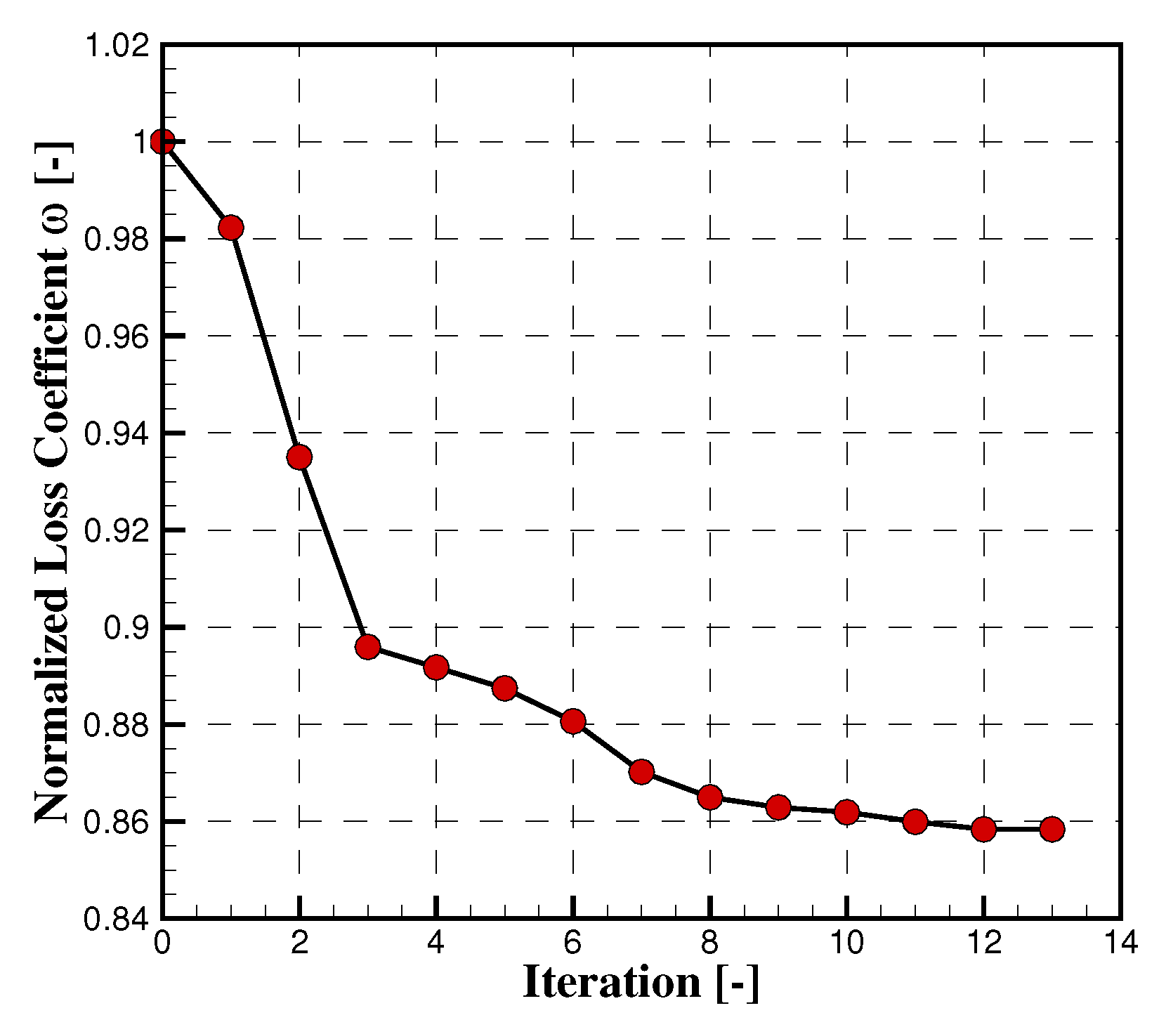
Figure 8.
Gradients L2 norm history.
Another important performance parameter for a volute is the pressure recovery coefficient, which characterizes the static pressure rise relative to the kinetic energy available at the inlet, such as defined in Equation (2). Its value goes from 0.61 in the baseline case, to 0.665 in the optimized one, which represents an increase of 9%. This is due to the increased mass flow as a result of the decreased losses.
To understand how shape modifications lead to loss reduction, it is important to recall the major loss mechanisms in a volute. The largest contributions to volute losses are caused by friction losses and non-isentropic deceleration. Additional losses can be generated indirectly through interactions with the impeller by circumferential pressure distorsion generated by the volute [17]. A volute converts the radial influx of mass into a tangential stream through the tangentially increasing cross sections. If the volute is too large, the cross-sectional area increases more than needed for the given influx, and an inefficient diffusion takes place in the azimuthal direction. A direct consequence is a circumferential distorsion at the volute inlet, which will introduce unsteadiness in the impeller. Conversely, if the volute is too small, the flow is accelerated along the circumference, which leads to a destruction of the pressure rise that was achieved in the impeller and thus, extra losses as well. Hence, the most important parameters are those that control the cross-sectional growth of the volute in the azimuthal direction. Zhenzhong Sun et al. [18] showed that the minimum volute radius and radius ratio distribution play a significant role in the compressor performance. In the present case, the minimum volute radius is decreased from 23 to 17.3 centimeters, as shown in Table 2, while the radius ratio distribution is changed. One can also observe that the inner wall radius stays at its upper bound value. The wall fillet radius is reduced to 1.0 mm which corresponds to its lower range limit, and the tongue radius is increased from 5 to 5.8 mm.
Table 2.
DESIGN PARAMETERS EVOLUTION.
| Index | Parameter Name | Baseline | Optimized | Units |
| 1 | Minimum volute radius | 0.023 | 0.017 | [m] |
| 2 | Wall height | 0.008 | 0.0074 | [m] |
| 3 | Wall fillet radius | 0.0025 | 0.001 | [m] |
| 4 | Wall radius | 0.195 | 0.195 | [m] |
| 5 | Inlet fillet radius | 0.001 | 0.0012 | [m] |
| 6 | Radius ratio point 2 | 1.4 | 1.22844 | [-] |
| 7 | Radius ratio point 3 | 1.6 | 1.45406 | [-] |
| 8 | Radius ratio point 4 | 1.7 | 1.72688 | [-] |
| 9 | Radius ratio point 5 | 1.75 | 2.06383 | [-] |
| 10 | Radius ratio point 6 | 1.9 | 2.22392 | [-] |
| 11 | Radius ratio point 7 | 2.1 | 2.26456 | [-] |
| 12 | Radius ratio point 8 | 2.3 | 2.35792 | [-] |
| 13 | Radius ratio point 9 | 2.5 | 3.08543 | [-] |
| 14 | Tongue radius | 0.005 | 0.0058 | [m] |
Figure 9 shows a cut at a constant Y plane in the main scroll (at an azimuthal position of 270 degrees), with total pressure map being displayed. The reduction in the cross-sectional area is apparent. The central low pressure zone corresponds to losses due to the shear forces at the center of the highly rotational flow, also called swirl losses. This contribution to the total losses can hardly be minimized due to the parametrization of the volute, as it doesn’t allow for modifications of the profile shape and inlet height. By extracting cross-sectional flow data at different azimuthal positions, the evolution of the mass flow averaged tangential velocity and area averaged static pressure along the volute circumference is computed, as presented in Figure 10. Following a simplified loss prediction model [19], it is possible to estimate the total pressure losses due to the drop in tangential velocity from the volute inlet to the center of each section, as presented in Equation (3):
with for decelerating flows and for accelerating flows. The quantity is the area averaged density and is the mass flow averaged tangential velocity at the inlet. These flow variables are equal to and for the baseline design. For the optimized design, is equal to . As an example, by taking an azimuthal position of 200 degrees, one can compute that the total pressure losses are in the baseline geometry, while they are at zero in the optimized case as there is no deceleration of the flow. This can be verified at different azimuthal positions and shows that the optimized area distribution allows to reduce the losses arising from inefficient diffusion along the volute. In contrast, the flow is decelerated in the baseline case which results in pressure rise along the circumference, as illustrated in Figure 10b, and additional diffusion losses.
Figure 9.
Cross section in Y plane.
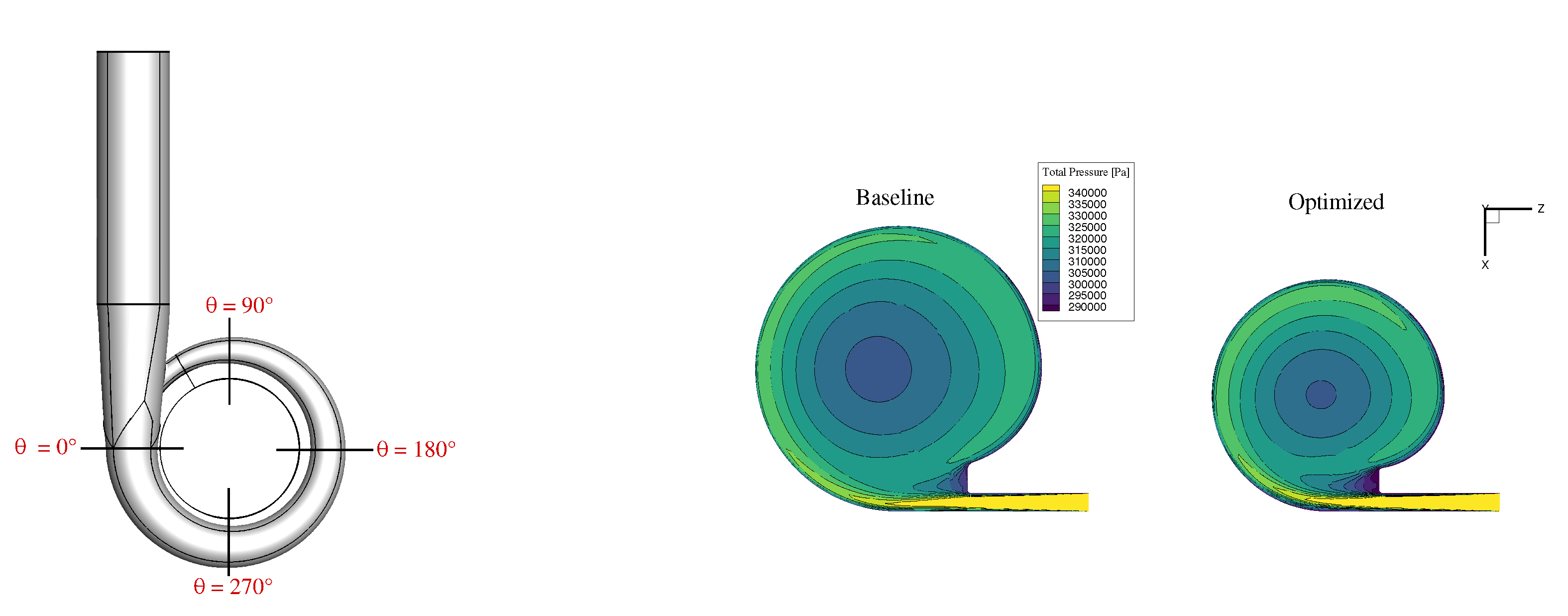
Figure 10.
Cross-sectional averaged flow data along the circumference.
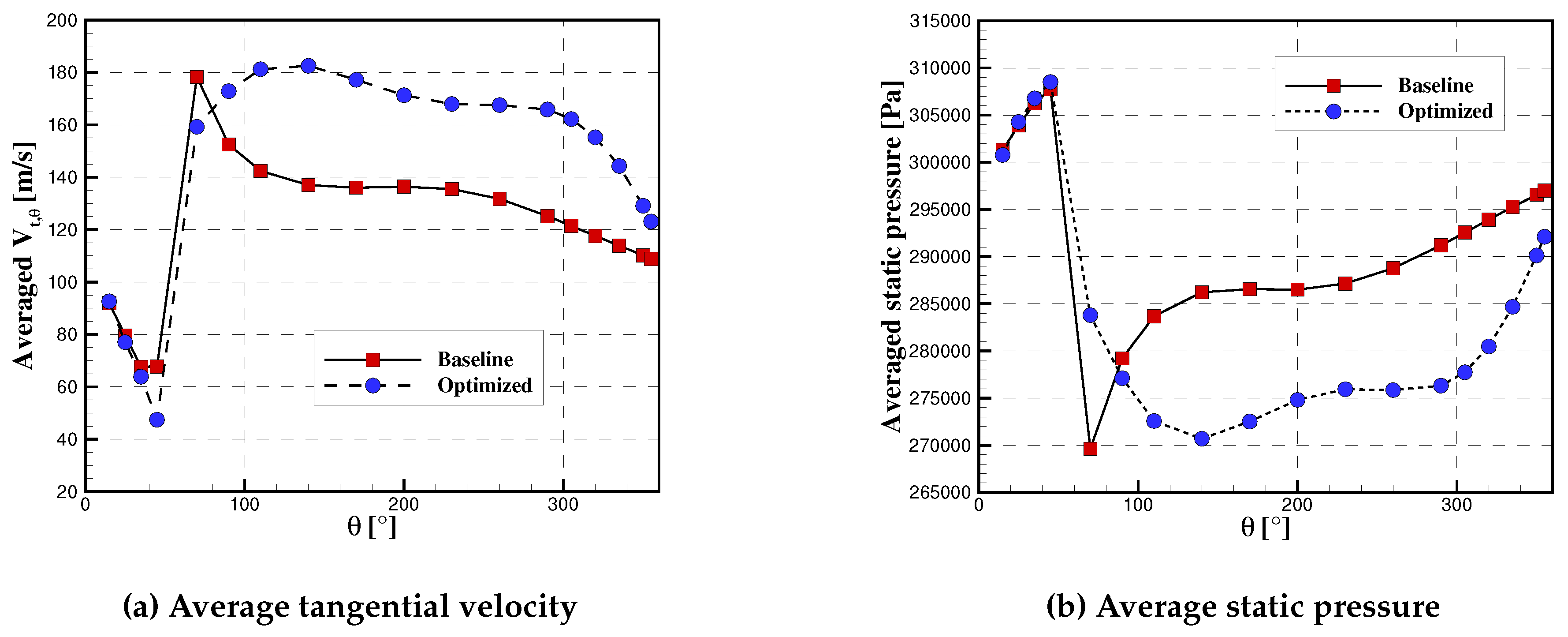
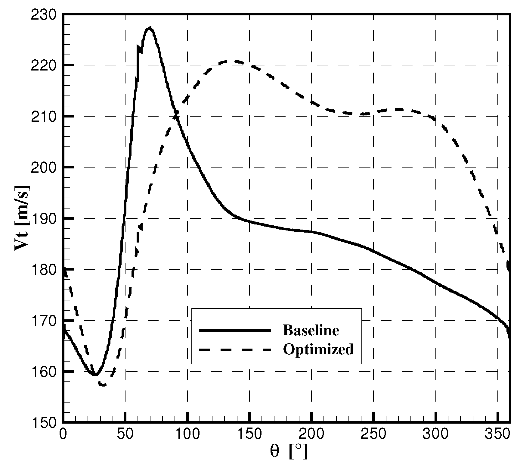
Figure 11 shows the static pressure distribution at a constant X-plane corresponding to the middle height of the inlet (i.e. X = 3mm). One can observe that the circumferential flow distribution benefits from the optimized shape with less distorsion compared to the initial design. To demonstrate the reduced level of distorsion at the inlet, the tangential velocity is extracted at a constant radius , that is one centimeter downstream of the volute inlet. The results are displayed in Figure 12. Again one can see the reduced flow distorsion close to the inlet, thanks to the optimized volute cross sectional area distribution. It can be shown that the radial velocity follows the same trend, as the inlet flow angle is imposed.
Figure 11.
Cross section in X plane.
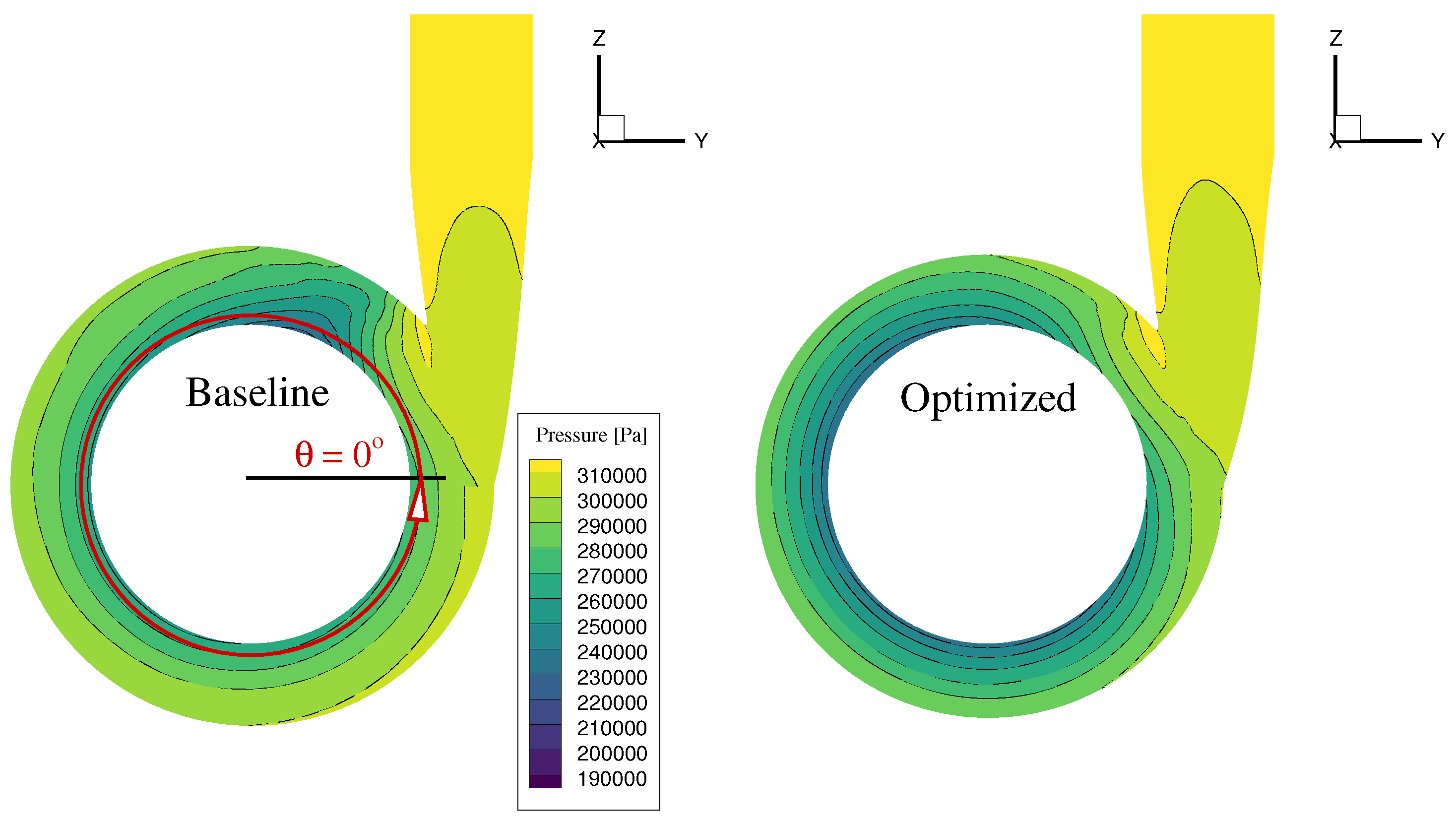
Figure 12.
Tangential velocity distribution along circumference.
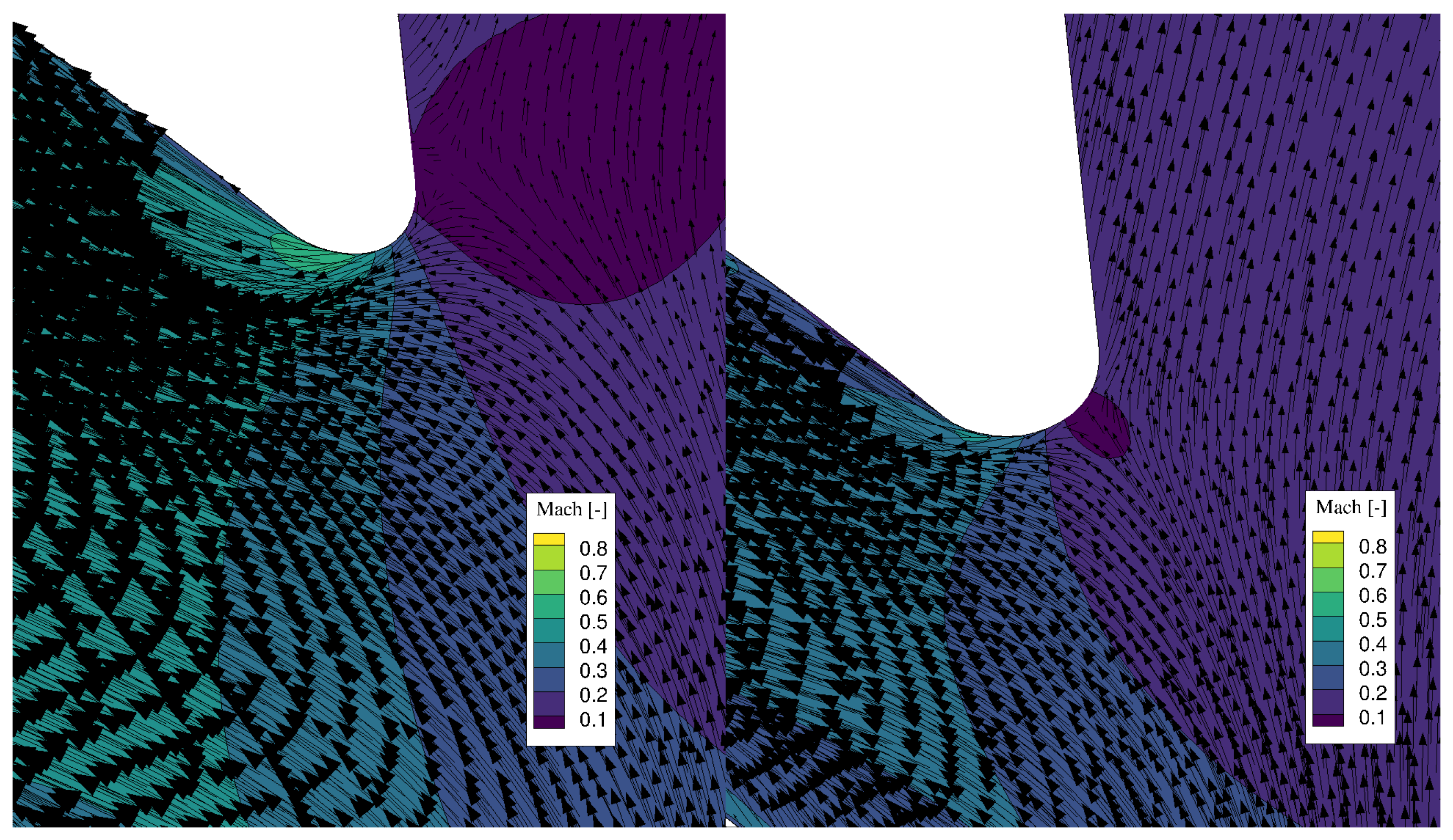
Finally, Figure 13 shows a close up on the tongue profile in a constant X plane. From this figure, one can deduce that the geometry is modified such that the tongue position is adapted to the flow angle, which results in lower losses. Indeed, the stagnation point is nicely located on the tongue in the optimized design, while it is shifted downstream inside the outlet diffuser in the baseline case, which leads to a larger flow separation close to the tongue wall, as shown by the velocity vectors. Similar observations can be found in [20].
Figure 13.
Zoom on tongue area - Baseline vs Optimized design.
2.6. Updated Compressor Map
The optimization of the volute has a direct impact on the compressor map, as an optimized volute design can increase the operating range of a pump or a compressor in addition to a better performance at design condition. The full-stage compressor map is recomputed using the optimized geometry. The results are shown in Figures 14 and 15. One can observe that the total-to-total pressure ratio and efficiency have both been increased thanks to the optimized volute. The curves are shifted towards higher mass flows as a consequence of the reduced losses. One should note that since a mixing-plane interface is used for the full-stage calculations, the impact on the impeller of less flow distorsion at the inlet of the volute cannot be measured. It can be assumed that with unsteady flow calculations, the new volute would potentially offer better performance on top of the steady improvements.
Figure 14.
Pressure ratio map.
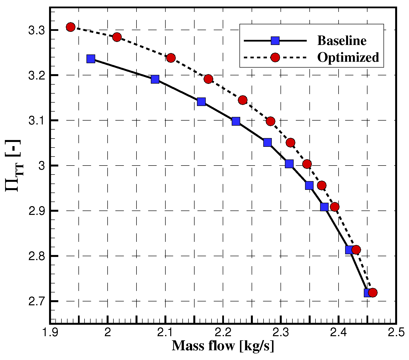
Figure 15.
Efficiency map.
3. Conclusions
In the present study, an adjoint-based design optimization of a volute is performed for the SRV2 radial compressor. After computing the compressor map of the full stage using a mixing plane interface, the volute design is optimized for flow conditions extracted at peak efficiency. The geometry is parametrized by means of 33 design variables, while the objective function is defined as the minimization of the loss coefficient. The optimizer converged to an optimal solution after 13 iterations, for which the losses are decreased by 14% compared to the baseline. It is shown that this reduction is mainly due to an adaptation of the volute size through a change in the minimum volute area and the modification of the area distribution along the circumference. The shape optimization also leads the tongue of the volute to be aligned with the inlet flow angle. The compressor map is recomputed and shows that the performance is improved on the whole operating range with in average above 1%. This gradient-based optimization of a volute constitutes an important step towards a full-stage optimization, which will allow to consider additional flow interaction processes.
Author Contributions
Conceptualization, R.Hottois., T.Verstraete. and A.Châtel.; methodology, R.Hottois., T.Verstraete. and A.Châtel.; software, R.Hottois.; validation, R.Hottois., T.Verstraete. and A.Châtel.; writing—original draft preparation, R.Hottois.; writing—review and editing, R.Hottois.; T.Verstraete. and A.Châtel.; visualization, R.Hottois.; supervision, T.Verstraete.; All authors have read and agreed to the published version of the manuscript.
Funding
This research received no external funding.
Conflicts of Interest
The authors declare no conflict of interest.
Abbreviations
The following abbreviations are used in this manuscript:
| R | Radius |
| h | Height |
| x | Design variable |
| Y | Grid coordinates |
| U | Flow solution |
| Inlet flow angle | |
| p | Static pressure |
| T | Static temperature |
| Efficiency | |
| Pressure loss coefficient | |
| Static pressure recovery coefficient | |
| V | Absolute flow velocity |
| Pressure ratio | |
| CFD | Computational Fluid Dynamics |
| RANS | Reynolds Averaged Navier-Stokes |
| SQP | Sequential Quadratic Programming |
| lb | Lower bound |
| ub | Upper bound |
| tot | Total |
| in | Inlet |
| out | Outlet |
| TT | Total-to-total |
| t | Tangential |
| r | Radial |
References
- Kim, J. H., Oh, K. T., Pyun, K. B., Kim, C. K., Choi, Y. S., and Yoon, J. Y., Design optimization of a centrifugal pump impeller and volute using computational fluid dynamics. IOP Conference Series: Earth and Environmental Science.2012,15032025. [CrossRef]
- Stepanoff, A. J.; Centrifugal and Axial Flow Pumps: Theory, Design, and Application; Krieger Publishing Company: Malabar, USA, 1993.
- Han, X., Kang, Y., Sheng, J., Hu, Y., & Zhao, W. Centrifugal pump impeller and volute shape optimization via combined NUMECA, genetic algorithm, and back propagation neural network.Structural and Multidisciplinary Optimization 2020, 61(1), 381-409. [CrossRef]
- Ji, C., Wang, Y., and Yao, L., Numerical Analysis and Optimization of the Volute in a Centrifugal Compressor. In Challenges of Power Engineering and Environment; K. Cen, Y. Chi, F. Wang (Eds.); Springer Berlin Heidelberg, Germany, 2007, pp. 1352–1356. [CrossRef]
- Huang J., Xu S., Liu H., and Wang X., Robust performance optimization of centrifugal compressor volute with a rectangular cross-section. In Proceedings of ASME Turbo Expo 2015: Turbine Technical Conference and Exposition, Montreal, Canada, No. GT2015-42979, 2015. [CrossRef]
- Heinrich M., Schwarze R., Genetic Algorithm Optimization of the Volute Shape of a Centrifugal Compressor. International Journal of Rotating Machinery 2016, 13. [CrossRef]
- Eisenlohr, G., Krain, H., Investigation of the flow through a high pressure ratio centrifugal impeller. In Proceedings of ASMETurbo Expo 2002: Power for Land, Sea, and Air, Amsterdam, The Netherlands, No. GT2002-30394, 2002. [CrossRef]
- Chatel A., Verstraete T., Aerodynamic optimization of the SRV2 radial compressor using an adjoint-based optimization method. In Proceedings of ASME Turbo Expo 2022, Rotterdam, Netherlands, June 2022. [CrossRef]
- Vladimir D. Liseikin; Grid Generation Methods, 3rd ed.; Springer Cham: New-York City, USA, 2017.
- Thompson, J. F., Warsi, Z. U. A., and Mastin, C. W.; Numerical Grid Generation: Foundations and Applications; North-Holland: Amsterdam, The Netherlands, 1985.
- Muller, L., Adjoint-Based Optimization of Turbomachinery With Applications to Axial and Radial Turbines. PhD Thesis, Universite libre de Bruxelles, Ecole polytechnique de Bruxelles, Bruxelles, 2019. [CrossRef]
- Wang, D., An Improved Mixing-Plane Method for Analyzing Steady Flow Through Multiple-Blade-Row Turbomachine. Journal of Turbomachinery.2014,136(8). [CrossRef]
- Giles, Michael B., Non-Reflecting Boundary Conditions for the Euler Equations.AIAA Journal 1990,28, 2050–2058.
- Martins, J. R. R. A., Sturdza, P., and Alonso, J. J., The Complex-Step Derivative Approximation.ACM Trans. Math. Softw. 2003, 29(3), 245–262. [CrossRef]
- Hottois R., Chatel A., Coussement G., Debruyn T., Verstraete T., Comparing gradient-free and gradient-based multi-objective optimization methodologies on the VKI-LS89 turbine vane test case. Journal of Turbomachinery. 2022, 145. [CrossRef]
- Rosemeier, J., Numerical Analysis of a Centrifugal Compressor Including a Vaneless Diffuser and a Volute. 2017.
- Van den Braembussche R.; Design and Analysis of Centrifugal Compressors; ASME Press, Wiley, 2019.
- Sun, Z., Zheng, X., Linghu, Z., Kawakubo, T., Tamaki, H., and Wang, B., Influence of volute design on flow field distortion and flow stability of turbocharger centrifugal compressors. In Proceedings of the Institution of Mechanical Engineers, Part D: Journal of Automobile Engineering 233(3), 2019; 484-494. [CrossRef]
- Japikse D., Advanced diffusion levels in turbocharger compressors and component matching. In Proceedings of First Int. Conf. on Turbocharging and Turbochargers, London, United Kingdom, pp. 143-155, 1982.
- Hamed Alemi et al., Effect of the volute tongue profile on the performance of a low specific speed centrifugal pump. Proceedings of the Institution of Mechanical Engineers, Part A: Journal of Power and Energy 2014, 229, 210-220. [CrossRef]
Disclaimer/Publisher’s Note: The statements, opinions and data contained in all publications are solely those of the individual author(s) and contributor(s) and not of MDPI and/or the editor(s). MDPI and/or the editor(s) disclaim responsibility for any injury to people or property resulting from any ideas, methods, instructions or products referred to in the content. |
© 2023 by the authors. Licensee MDPI, Basel, Switzerland. This article is an open access article distributed under the terms and conditions of the Creative Commons Attribution (CC BY) license (http://creativecommons.org/licenses/by/4.0/).
Copyright: This open access article is published under a Creative Commons CC BY 4.0 license, which permit the free download, distribution, and reuse, provided that the author and preprint are cited in any reuse.


