
Submitted:
03 August 2023
Posted:
03 August 2023
You are already at the latest version
Abstract
In the past decade, under the background of the carbon peaking and carbon neutrality era, the rapid development of new energy vehicles has put forward higher requirements for the performance of strike forces such as battery cycle life, energy density and cost. Lithium-ion batteries have gradually become the mainstream of electric vehicle power batteries due to their excellent energy density, rate performance and cycle life. At present, the most widely used cathode materials for power batteries are lithium iron phosphate (LFP) and ternary nickel-cobalt-manganese (NCM). However, these materials exhibit the bottlenecks that limit the improvement and promotion of power battery performance. In this review, the performance characteristics, cycle life attenuation mechanism (including structural damage, gas generation and active lithium loss, etc.) and improvement methods (including surface coating and element-doping modification) of LFP and NCM batteries are reviewed. Finally, the development prospects of this field are proposed.
Keywords:
lithium iron phosphate (LFP)
; nickel-cobalt-manganese (NCM)
; cathode materials
; power battery
; cycle life
; attenuation mechanism
1. Introduction
Since the invention of lead-acid batteries in the 1880s, batteries have been closely related to the development of transportation ways. The development of power batteries has become crucial to the development and popularization of electric vehicles that meet the ‘dual carbon’ requirements of ‘carbon peaking and carbon neutrality’. Nickel-chromium battery, nickel–metal hydride battery, and lead-acid battery have all been used for electric vehicles. However, due to the inadequacy of the battery's multiplying performance, capacity, and cycle life, it is difficult to meet the requirements of electric vehicles, so it is gradually eliminated. Lithium ion batteries (LIBs) exhibit high battery capacity and excellent cycling performance, making them the most promising power batteries in the field of electric vehicles. However, further improvements in cycle life and cost reduction are still needed. Considering the factors such as long life, rate performance, energy density, cost effectiveness and safety, the lithium iron phosphate (LFP) and ternary battery (NCM) based lithium-ion batteries have become the best choice for electric vehicle power batteries, with a total market share of more than 90%. This review provides an overview of the performance characteristics and main factors affecting cycle life attenuation of LFP and NCM lithium-ion batteries. The main strategies to improve the performance and development prospects are proposed [1,2,3].
2. Properties of LFP and NCM
The performance and cost of electric vehicles is largely determined by power batteries. The application cost of power batteries is mainly determined by their cycle life. As shown in Table 1, considering that the electric vehicle is charged once every two days, the lead-acid battery can be used for two years; the nickel-metal hydride battery can be used for four years, while the LIBs can be used for even eight years. Furthermore, the energy density of the LIBs is 2-3 times that of the lead-acid battery and nickel-metal hydride battery, which can reduce the dead weight of the battery while extend the driving range.
The cathode materials of LIBs include LFP, NCM, lithium cobalate (LCO) and lithium manganate (LMO) et al. As shown in Table 1, LFP shows extremely high cycle life, voltage platform and energy density, which can effectively reduce the dead weight of the battery and ensure the acceleration ability of electric vehicles. NCM also exhibits high energy density, cycle life and Li+ diffusion ability. In particular, NCM displays good rate performance during high rate discharge, which can support the high-power charging demand of power batteries and the high current required for electric vehicle acceleration. However, due to the increasing prices of precious metals in recent years, the popularity of ternary batteries has been limited. LCO has a high specific capacity and battery voltage of 4.2V, leading to high energy density [2]. However, due to the phase transition of LCO during lithium removal and insertion, Co is unstable and prone to dissolution under high voltage platforms. The side reactions between dissolved Co and electrolyte or anode can lead to serious safety and limit the application of LCO. In addition, the low diffusion coefficient and conductivity of Li+ in LMO severely limit its application in high rate discharge [3]. In summary, LFP and NCM show advantages in cost effectiveness and performance, making them the mainstream of electric vehicle power batteries.
3. Lithium Iron Phosphate (LFP) Battery
3.1. Structure and Properties of LFP
LFP has an olivine crystal structure [9], which transforms into FePO4 (FP) phase during the discharge process. Due to the similar crystal structure of the two phases, the volume change of the crystal cell before and after discharge is only 6.81%. Therefore, the internal stress formed in LFP is relatively small during the charging/discharging processes [10]. In addition, the P-O chemical bond is strongly stable, and thus the oxygen in the lattice is not easy to be lost. The stable crystal structure and very small internal stress make LFP extremely stable in structure, with cycle life reaching more than 2000 times and high safety [11]. Unfortunately, the Li+ diffusion coefficient and conductivity in LFP are very low due to two reasons: (1) in the LFP lattice (see Figure 1), electrons propagate through the transition metal layer, and each FePO4 is separated by an oxygen atom, with only one common vertex oxygen acting as the connection point. Therefore, LFP is almost an insulator, with an electron conductivity of only 10-9s/cm; (2) the diffusion channel of Li+ is one-dimensional, and the PO4 tetrahedron hinders the diffusion of Li+ in the c-axis direction, which increases the diffusion resistance of Li+ between LFP and FP phases.
3.2. Life Attenuation Mechanisms of LFP Batteries
Padhi et al. [12] proposed a core-shell model for lithium extraction/reinsertion of LFP particles, as shown in Figure 2a. The LFP/FP interface moves inward when lithium is extracted from the cathode particles to form FePO4. Due to the low conductivity and Li+ diffusion coefficient of LFP, the LFP inside the particles cannot fully extract Li+ and electrons, which can easily lead to capacity loss. Andersson et al. [13] used improved the core shell model and proposed a mosaic model, as shown in Figure 2b. In this model, the extraction and insertion of lithium can occur at random sites in the particles. The lithium extraction regions form inactive Li+ isolated regions when they collide with each other, and during discharge, Li+ is re-embedded into the LFP. The core FP is not fully converted, and some LFP is enveloped by FP, which can also cause capacity loss. Compared with the core-shell model, the mosaic model proposes that the lithiation and delithiation of LFP are not uniformly embedded and removed from the particle surface in the usual sense, but exhibit significant heterogeneity. The above two models may explain the reason for capacity decay: (1) the deactivation of some lithium rich LFP particles; (2) some FP in the particle core is not fully converted, resulting in the loss of active lithium. The factors causing the above two types of capacity attenuation can be attributed to the low Li+ diffusion rate and low electron conductivity of LFP and FP phases, which limit the conversion of the two phases inside the particles. In recent years, researchers have improved the cycling stability and rate performance of LFP by reducing its particle size. The reduction in particle size enhances the migration ability of Li+ in the LFP and FP phases and promotes the mutual transformation of the two phases.
Although the above model well explains the mechanism of capacity loss in LFP, it does not take into account the properties of one-dimensional lithium channels in olivine structured LFP. Fan et al. [14] combined transmission X-ray microscopy (FF-TXM) with X-ray absorption near edge structure (XANES) spectroscopy and tomography reconstruction to analyze the phase distribution of LFP secondary particles, as shown in Figure 2c. It is found that the FP domain in the particles exhibits a filamentary feature with a large transverse to longitudinal ratio. Since the [100] direction has the maximum lattice mismatch of 5% ([001] 1.9%, [010] 3.6%) between LFP and FP, the FP phase tends to grow in the vertical [100] direction because it can minimize the strain energy. When the FP phase extends to the grain boundary, the growth direction of the FP phase tends to change to the path with minimum resistance, as shown in Figure 2d. The characteristic of FP phase distributed in a fine filament during LFP lithium removal process further indicates that the formation of FP phase in the mosaic model is not random. Yang et al. [11] investigated the polarization of LFP/FP two phases under different residual charges (SOC) of LFP secondary particles, as shown in Figure 2e. When SOC<10%, FP phase tends to be formed on the surface. As SOC increases, the growth and polarization degree of FP phase on the surface increases, and gradually extends to the interior of the particles, which is consistent to the mosaic model. When SOC>60%, the FP phase condenses with each other to form a core-shell structure, and the polarization degree of 2C high rate discharge is greater than that of 0.1C low rate discharge. This indicates that the embedding of lithium is accompanied by obvious polarization phenomenon, and polarization intensifies during high rate discharge. A large polarization voltage will not only lead to the appearance of lithium deposition, but also reduce the operating voltage, resulting in a decrease in cycle performance and energy density. In addition, due to a 6.8% volume difference between LFP and FP, internal stress is generated and structural collapse may occur, resulting in the pulverization of the cathode particles.
3.3. Modification Methods for LFP Batteries
Compared with other electrode materials, LFP has good structural stability and excellent cycle life. Sun et al. [10] found that no significant structural damage occurred in the LFP electrode after cycling for 1500 times at a rate of 0.5C. However, the low conductivity and Li+ diffusion coefficient of LFP reduce the rate performance of LFP batteries, generate polarization phenomena, and cause loss of active substances. Therefore, current modification methods of LFP mainly focus on improving conductivity and Li+ diffusion coefficient of LFP. The common methods include reducing particle size, coating, and doping. Among them, reducing the particle size can effectively improve the migration ability of Li+ in LFP. However, reducing the particle size may reduce the compacted density, increase the specific surface area, and trigger side reactions between the electrode and electrolyte. Therefore, reducing the particle size of LFP has to be combined with coating or doping.
3.3.1. Metal Doping Modification of LFP
Element doping is considered to be the most effective method to improve the electric conductivity and ion diffusion rate of LFP. The element doping usually occurs at the Li or Fe sites. Appropriate element doping has the following positive effects on LFP: (1) expanding the diffusion channel of Li+, reducing the bond energy of Li-O, which is beneficial for the insertion and extraction of Li+; (2) increasing the density of Li vacancies is beneficial for the diffusion of Li+; (3) reducing the bandgap width of the two phases to increase electric conductivity. Yan et al. [15] used a solid-state method to prepare Mg-doped LFP/C samples and found that the discharge capacity of LFP did not change very much before and after doping at low current, while the discharge capacity of doped LFP was much better than that of un-doped samples at high current. This is because Mg-doping improves the intrinsic conductivity of the electrode, resulting in a significant increase in cycle life. The capacity retention rate of 1000 high rate discharges at 10C can reach 80%, while the capacity retention rate of un-doped LFP is only 49% [16]. Doping can limit grain growth, shorten Li+ diffusion distance, and improve electronic conductivity. Usually, impurity atoms tend to replace each other with elements with similar radius at the doping sites, but not all doped atoms can enter the LFP lattice. Doped atoms that do not enter the lattice may affect the diffusion of Li+, so it is necessary to control the appropriate doping amount [17]. Tao et al. [18] doped the Fe site by Nb by solid-state sintering. As the ion radius of Nb5+ is smaller than Fe2+, the bond length gets shorter, leading to enhanced crystalline stability. Moreover, due to the different valence states of Nb5+ and Fe2+, the lattice defects and vacancies are introduced after doping, which improves the conductivity of the material. The capacity of LFP before doping is 137.49 mAh·g-1, with capacity retention rate 95.44% after 100 cycles at a rate of 1C. After Nb5+ doping, the capacity increased to 169.87 mAh·g-1, and much improved capacity retention rate of 99.03% after 100 cycles at a rate of 1C.
3.3.2. Nanosizing and Carbon Coating of LFP Particles
The conductivity of LFP is only 10-9~10-10 cm2·s-1, while the conductivity of the most commonly used graphite is 10-6 cm2·s-1. The conductivity of LFP, which is close to that of insulators, severely restricts its rate performance. Nanosizing and surface coating are effective modification methods for LFP particles. As the ion conductivity and electronic conductivity at the particle interface are larger than those inside the particle, and the diffusion distance inside the LFP particle can be shortened. Thus, the nanosizing can significantly improve the conductivity and ion diffusion rate. However, the creation of nanoparticle significantly increases the specific surface area of the particle in contact with the electrolyte, which often leads to serious electrode electrolyte interface side reactions. Carbon coating can alleviate the problem of interface side reactions. Duan et al. [19] prepared electrode materials coated with dense carbon by mixing LFP particle of average size 42nm with glucose solution. The energy density of the prepared battery was 152 mAh·g-1, slightly lower than the theoretical value of 170 mAh·g-1, but showed higher cycle stability and rate performance (capacity loss only 0.3-1.1% after 1000 cycles at 10C rate). The common coating materials for LFP particles include carbon materials, metals and metal oxides, ion conductive materials, etc. Considering the increasing requirements for cost effectiveness and manufacturing feasibility, process of power batteries, carbon material coating seems to be the most reliable solution. According to the coated carbon source, the coating method can be divided into inorganic carbon source (e.g. carbon black, carbon nanotubes, graphene, etc.) and organic carbon sources (e.g. sucrose, glucose, starch, etc.). According to the morphology of coated carbon, the coating method can be divided into one-dimensional carbon (carbon fibers, carbon nanotubes), two-dimensional carbon (graphene), three dimensional carbon (carbon nanotube array, graphene skeleton), as shown in Figure 3.
It is crucial to select an appropriate method to form a uniform carbon coating layer on the surface of LFP based on the coated carbon source. Common coating methods include: (1) non-in-situ carbon coating (preparing LFP first and then coating), (2) in-situ carbon coating refers to the addition of organic carbon sources (sucrose, glucose, citric acid, etc.) to the LFP precursor, simultaneously forming a carbon layer and LFP. The preparation methods include solid-state preparation, wet preparation and gas-phase preparation, etc. In-situ carbon coating can form almost all kinds of carbon coating. Guan et al. [21] first synthesized LFP/activated carbon composite with a size of 100-300nm by solvothermal method, then mixed the composite with graphene oxide, and finally carried out sol heat treatment to prepare LFP/activated carbon/graphene composite, as shown in Figure 3b. The capacity was increased from 105mAh·g-1 in LFP to 156.3mAh·g-1 in LFP/activated carbon and 167.3mAh·g-1 in LFP/activated carbon/graphene. Furthermore, the capacity retention rate of LFP/activated carbon/graphene reached 96.3% after 300 cycles at a high rate of 30C. Guo et al. [22] synthesized LFP/C composite materials by modifying with carbon nanotubes (CNT). The surface of LFP has a carbon coating layer with thickness 2-3nm, and LFP/C nanoparticles closely contact with CNT to form a three-dimensional network (Figure 3d). This coating treatment reduced the polarization effect from 332.7 mV in LFP to 63.3mV in LFP/C and 45.6 mV in LFP/C/CNTs, indicating a significant improvement in the diffusion coefficient and conductivity of lithium ions. It should be noted that although carbon coating of LFP has achieved improvements in conductivity and rate performance, it sacrifices the compacted density of the battery and reduces the volume specific energy density. To reduce the impact of coating on the energy density of nanoscale electrodes, the coating process should be improved to prepare thinner and denser nano thickness carbon layers in the future.
4. Ternary Material (NCM) Batteries
4.1. NCM Structure and Properties
The ternary NCM material has a layered structure, and Li+ can diffuse in the layered two-dimensional plane, resulting in a high diffusion rate, as shown in Figure 4a. Li+ occupies the 3a position of the (1,1,1) crystal plane, transition metal (TM) ions occupy the 3b position, and O2+ occupies the 6c position. The TM layer can be randomly occupied by Ni, Co, and Mn, and each TM atom is surrounded by six oxygen atoms to form an octahedral structure. During the charging and discharging process, Li+ reversibly embeds and detaches between layers, and different TMs play a synergistic role: (1) Ni is an active substance, and during the charging and discharging process, Ni+/Ni3+, Ni3+/Ni4+ pairs provide capacity. The higher the Ni content, the higher the capacity of the ternary battery. However, due to the similar radii of Li+ and Ni2+, the mixing of Li+ and Ni2+ ions intensifies with the increase of Ni content. When the Ni content is higher than 80%, the cycle life of the ternary cathode rapidly decays. As shown in Figure 4b, with the increase of Ni content, both thermal stability and capacity retention rate decrease, while the capacity increases. (2) Co can effectively stabilize the layered structure of ternary materials, inhibit cation mixing, improve the conductivity of the material and improve cycling performance. (3) Mn can reduce costs, improve the structural stability and safety of materials. The ternary material LixNiyMnzCo(1-x-y)O2 has a diverse composition and the electrochemical performance can be further improved by doping, which has broad development prospects.
4.2. Life Attenuation Mechanism of NCM Battery
High nickel ternary NCM materials possesses high specific capacity, but still exhibit a series of problems including (1) mechanical damage caused by phase transition during cycling and loss of lattice oxygen, (2) the surface and internal crack surface of particles react with air and electrolyte to form a passivation film, reducing conductivity and ion diffusion rate, and causing structural damage to the electrode material due to expansion [25].
4.2.1. Mechanical Damage of NCM Particles
As shown in Figure 5, the NCM secondary particles are composed of many primary particles. Accordingly, the mechanical damage of the electrode particles can be divided into intragranular damage of the primary particles and intergranular damage of the secondary particles.
The secondary particles shorten the propagation path of Li+ and electrons, thereby improving the rate performance of the electrode. As shown in Figure 6, the trend of Li+ changes in secondary and primary particles is roughly the same, which can be divided into three stages, including growth stage, stable stage, and decrease stage. The reason for the increase in diffusion coefficient in the first stage can be attributed to the increase in the concentration of lithium vacancies. The decrease in diffusion coefficient in the third stage is due to the decrease in crystal interlayer spacing (Li+ diffusion channel) when the lithium removal reaches about 70% and the crystal structure transitions to H3. Whether during charging or discharging, the diffusion coefficient of Li+ is much higher than that in primary particles. At the same time, nanoscale primary particles have serious side reactions and high production costs. Therefore, at present, electrode materials for electric vehicle power batteries are mainly secondary particles.
4.2.1.1 Intergranular Damage
Intergranular damage occurs in secondary particles and is caused by differences in the volume change between different phases. During the process of lithium removal, the crystal structure of ternary materials undergoes a series of H1-M-H2-H3 phase transitions, and the phase composition is closely related to the degree of lithium removal [28]. Xu et al. [29] measured the phase composition of LixNiO2 and found that the phase composition is closely related to the voltage plateau and the amount of lithium removed. Due to the fact that the parameters of H2 phase on the c-axis are much smaller than those of H3 phase, it is widely believed that intergranular cracks are caused by the H2-H3 phase transition [30]. The arrangement of primary particles is random, and the internal stress generated by the contraction and expansion of adjacent primary particles acts on the grain boundaries. During the charging and discharging cycles, intergranular cracks expand, as shown in Figure 7a. The Coulombic efficiency is usually between 70-95% during the first cycle of the battery. On the one hand, it is due to the formation of a passivation layer on the electrode electrolyte surface, which consumes some active lithium. On the other hand, it is due to intergranular damage caused during the first cycle [31,32]. Feng et al. [30] measured the lattice change rate on the c-axis after 2 and 30 cycles of undoped LiNi0.9Co0.1O2 (UM) and LiNi0.9Co0.1O2 (PM) doped with 5% Ti, as shown in Figure 7b. After two cycles, the change rate of PM lattice on the c-axis is -5.1%, and the change rate of UM is -5.3%. After 30 cycles, the lattice change rate of PM on the c-axis changed from -5.1% to -5.0%, and the lattice change rate of UM on the c-axis changed from -5.3% to -3.3%. The lattice change rate on the c-axis significantly decreases during 2-30 cycles, indicating that the strain caused during the first cycle decays during the following cycles and H2-H3 phase transition has a certain degree of reversibility.
In addition, the cracks in secondary particles experience gradual propagation from the center to the surface during cycling, as shown in Figure 8a and b. This phenomenon is related to the phase transition that occurs during SOC and deblocking processes [33]. Deng et al. [34] took the chemical phase diagram of NCA particles, as shown in Figure 8c. In the diagram, the red part has strong activity, the blue part has weak activity, and the outermost and innermost redox activities of the secondary particles are the weakest. The weak activity of the outer layer is caused by a series of side reactions between the electrolyte and the surface of secondary particles, which reduces the oxidation-reduction activity of nickel on the surface of particles. The weak activity of the inner layer is due to cracks inside the secondary particles (the material at the center of the particles has a low degree of lithiation, and the SOC of the inner layer is lower than that of the outer layer, resulting in internal stress and the formation of cracks). In addition, the H3-H2 phase transition during the lithium intercalation process can also explain the phenomenon of cracks originating from inside the particles: the electrode particles after complete lithium removal are H2 phase. As the lithium intercalation process progresses, the H3 phase gradually forms from the surface of the particles inward, forming a core-shell structure. Since the parameters of the H2 phase inside the core-shell structure on the c-axis are much smaller than those of the external H3 phase, the internal stress in the H2 phase leads to the formation of cracks. When the crack extends to the surface of the particle and forms a penetrating crack, the electrolyte may enter the particle and undergoes interfacial reactions, resulting in an increase in the internal resistance of the electrode material. The volume expansion of the electrode electrolyte interface can also lead to particle breakage.
4.2.1.2 Intragranular Damage
The lattice strain occurs in the cathode particles during the lithium intercalation cycle, and the shrinkage and expansion cycle lead to the intragranular damage of the primary particles. Compared to secondary particles, primary particles are less prone to damage due to their micron size. The stress gradient inside and outside the particles is small, making it difficult to generate cracks internally. Moreover, propagation only occurs when the crack size is greater than the critical size. Therefore, small-sized primary particles are difficult to reach the critical size for crack propagation. The comparison of the strain energy inside the particle and the fracture surface energy (2γ) can be used as a criterion for evaluating the critical size of particles. Tao et al. [37] proposed a method for predicting whether cracks can be stable within a single crystal using an induced stress model, as shown in Equ. (1):
where h is the height of the cylindrical particle, α is the concentration expansion coefficient, E0 is the Young's modulus of non lithiated particles, E is the Young's modulus at a given lithium ion concentration, CR is the surface lithium ion concentration, and C0 is the center lithium ion concentration, ν is Poisson's ratio, ξ represents dimensionless stress and γ is surface energy.
Enrico et al. [27] conducted charging experiments on the secondary and primary particles of NCM ternary materials at different voltages. It is found that the secondary particles began to crack at 3.8V, while the primary particles did not show significant changes until 4.2V, indicating that the primary particles show much higher structural stability than secondary particles. Therefore, the cathode particle mechanical damage mainly occurs within the secondary particles.
4.2.2. Loss of Lattice Oxygen
In electrode materials that are rich in transition metals, the lattice oxygen is unstable. When the degree of lithium removal in high nickel ternary materials is significant, the content of easily reducible high valence Ni is high. In order to balance the charge inside the transition metal layer, the TM-O bond may break and generate oxygen vacancies, which will detach in the form of gas and loss of lattice oxygen. Liu et al. [38] recorded the stress-strain behavior of cathode particles at different voltages during the discharge process of NCM electrode materials rich in Li and Mn using Bragg coherent diffractive imaging (BCDI) and electrochemical mass spectrometry. As shown in Figure 9a and b, in the first stage (3.75-4.43 V), there is no significant gas overflow related to oxygen. When the voltage increases to 4.43 V, the tensile strain of the particles reaches its maximum value, and the electrostatic repulsion force between the oxygen layers reaches its maximum, indicating that the cathode particles are almost completely de-lithium; In the second stage (4.43-4.51 V), the release of lattice oxygen significantly intensifies, and the particle tensile strain gradually decreases until the strain disappears at 4.51 V, indicating a close correlation between the cathode particle strain and gas production.
The release of lattice oxygen leads to structural degradation, capacity loss, and exacerbates side reactions, resulting in a series of safety issues. Clare et al. [39] studied the chemical decomposition of electrolyte on the NMC electrode by gas testing and nuclear magnetic resonance spectroscopy (NMR). The diversity of decomposition products generated on the positive side was clarified, and it was observed that the release rate of oxygen containing-compounds changed with the voltage, as shown in Figure 9c. This fact indicates the diversity of gas production from the reaction between the cathode material of a ternary battery and the electrolyte, and the gas production is closely related to the voltage platform.
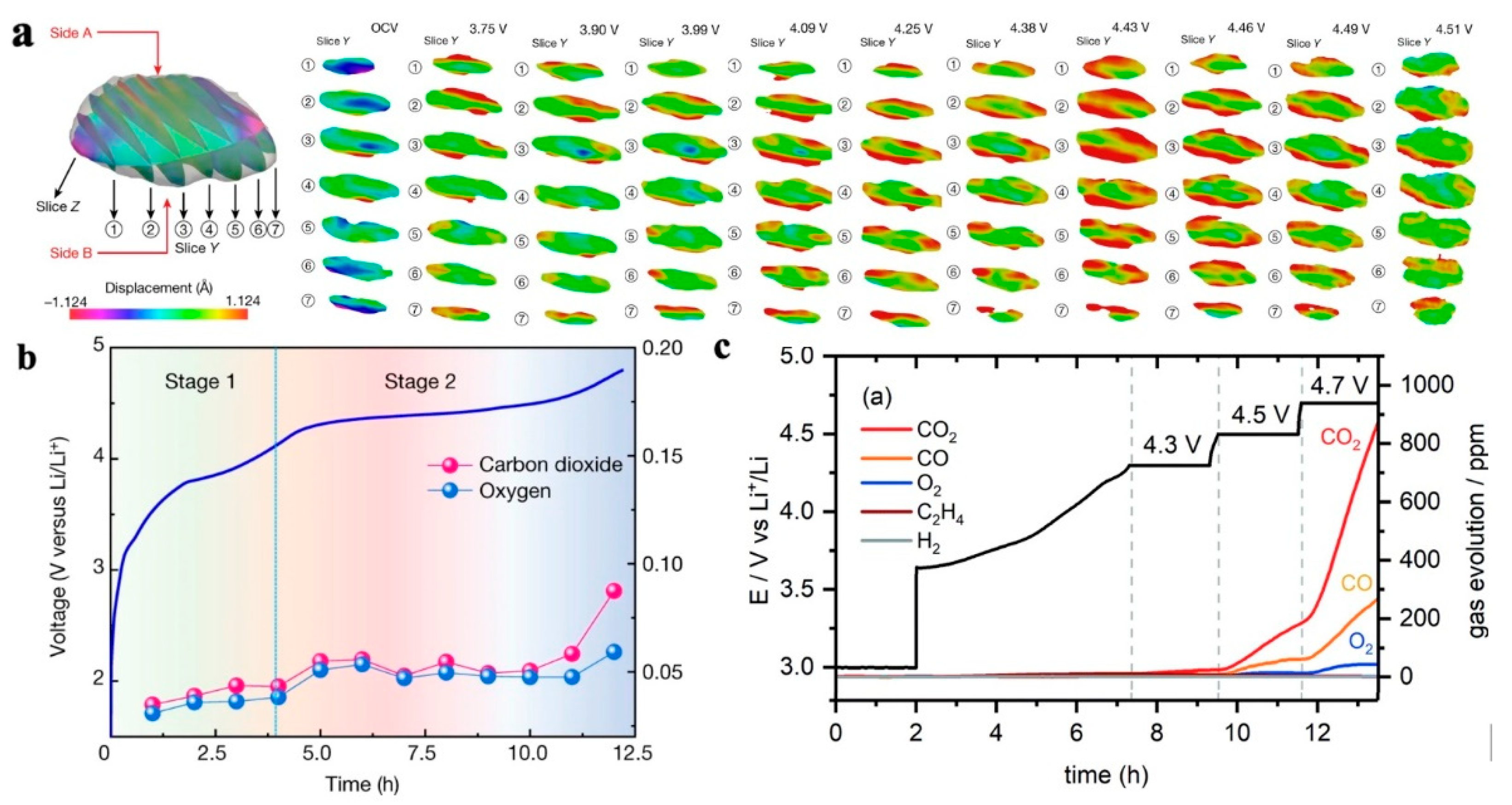
Figure 9.
Release and gas production of lattice oxygen in ternary NCM material. (a) Bragg coherent diffractive imaging (BCDI) of the particles in the strain field, wtih compressive strain in blue and tensile strain in red [38], (b) Electrochemical mass spectrometry of primary particles [38], (c) Time-dependent variation curve of gas production [40].
4.3. Modification Methods for NCM Ternary Materials
4.3.1. Surface Coating Modification
As mentioned earlier, ternary material particles inevitably undergo structural damage during cycling. Typically, cracks propagate from the center to the surface of the particles. As a result, the electrolyte enters the interior of the cathode particles to form a passivation film, resulting in adverse effects such as particle volume expansion, reduced conductivity and Li+ diffusion rate. At present, coating is the most effective method to improve the cathode materials without changing the existing their manufacturing technologies. As shown in Table 2, the coating morphology on the particle surface can be divided into two types: homogeneous coating and island coarse coating. The coating morphology is directly related to the coating process [41]. By vapor chemical technology (atomic layer deposition, chemical vapor deposition), the coating with a thickness of 0.1nm can be prepared, and the coating thickness can be increased by successive deposition [42].
According to the data in Table 2, coatings can significantly improve cycling performance due to the following three reasons: (1) coatings can serve as supporting structures to alleviate stress caused by phase transformation and improve the structural stability of particles; (2) homogeneous coating can better form a physical barrier to reduce the occurrence of side reactions; (3) the coating materials are mostly metal oxides, which can neutralize HF, reduce acidity, and reduce the migration of transition metals. Although homogeneous coating is technically feasible, the application of homogeneous coatings in large-scale production is not feasible for power batteries due to the high cost. On the other hand, island-like coating shows great development prospects due to its economic efficiency. Island coatings can be prepared using both dry and wet processes, which are both operational feasible and cost effectiveness. Compared with wet methods, the dry coating process is more cost-effective and environmentally friendly, which helps in the industrial production of power batteries [42].
4.3.2. Elemental Doping Modification of NCM
The volume change and gas generation of ternary materials are closely related to their cyclic phase transition. Another effective method to suppress phase transition is bulk doping. According to the classification of doping sites, it can be divided into Li-site doping, TM-site doping, and O-site doping. Different doping sites also have different improvements in material properties [50]. Compared with the LFP olivine structure, the stability of the NCM layered structure is relatively poor, and the composition is more diverse. Therefore, doping has a more significant impact on the performance of ternary materials. Among them, Li-site doping can not only increase vacancies but also reduce the mixing of Li/Ni, preventing Ni migration. Due to the introduction of elements with higher valence states than Li+, the valence state of Ni will decrease according to the conservation of valence states. Furthermore, constant valence metal elements such as Mg will generate pillar effects in the lattice, thereby improving the stability of the structure. Introducing stronger TM-O bonds (such as Al, Ti, Zr, etc. [42]) at the TM site can effectively stabilize the crystal structure, prevent lattice oxygen loss and suppress harmful H2-H3 phase transitions, thereby improving thermal stability and cycle life.
5. Conclusions and Outlooks
This article reviews the material structures, performance degradation mechanisms, and odification approaches of the two most commonly used power batteries, LFP and NCM. The impact of coating and doping modification on the performance has been summarized. The main conclusions are as follows:
- The olivine crystal structure of LFP resulted in its low conductivity and ion diffusion rate, leading to partial deactivation of the cathode particles, loss of active lithium, and lower rate performance, limiting the charge and discharge rate in the battery.
- LFP lithium removal exhibited significant heterogeneity. FP phase distributed in a fine filament shape and accompanied by regional condensation, leading to polarization of the LFP/LP phases in the cathode particles. The uncoordinated polarization behavior between the two phases induced internal stress within the particles, leading to cracks and structural damage of the particles.
- The size of the first order particles in ternary NCM materials affected the generation of cracks during their cycling process. When the first order particle size was smaller than the crack initiation critical size, internal cracks in the first order particles were hard to initiate and propagate.
- The H2-H3 phase transition can induce cracks in the secondary particles during cycling of the secondary particles in ternary NCM materials. The electrolyte may enter the interior of the particles through microcracks and form a passivation film on the surface of the cracks, increasing the volume of the particles and causing breakage of the particles.
- The phase transition of ternary NCM materials induced lattice oxygen release and structural degradation. In addition, various gases such as CO2, CO, O2, H2, C2H4 can be generated, causing safety issues and structural damage.
Based on the performance degradation principle of LFP and NCM materials, in-depth research works are needed in the field of composition design, material nanosizing, coating, and doping to further improve battery performance and solve the bottleneck problems of life degradation. The main approaches include:
- The nanosizing and coating of cathode materials need to be applied simultaneously to improve conductivity, ion diffusion rate, and reduce side reactions at the electrode electrolyte interface. For LFP, its interfacial conductivity can be improved by coating, such as carbon coating that shows good coating effect and economic benefits. However, for ternary NCM materials, the coating material needs to serve as a support and physical barrier, requiring carefully control of the type and morphology of the coating material. At present, it is still difficult to achieve a thin and uniform coating on the surface of NCM on the basis of low cost, which affects the vibration density and energy density of electrode materials. Further development of coating processes is needed for LFP and NCM to reduce coating costs and increase energy density.
- The main purpose of LFP doping is to improve the conductivity and ion diffusion rate of the material, while the main purpose of ternary NCM material doping is to suppress phase transition. Current research works are mostly focused on single atom doping. Due to the limited performance improvement of single atom doping, further research is needed on multiple atoms co-doping, elucidating the doping ratios and synergistic effects of multiple doped atoms, and seeking low-cost doping processes.
Author Contributions
Conceptualization, G. Zhang, Z. Jia, N. Cui and Y. Xiong; methodology, G. Zhang, M. Li, Z. Ye and Z. Jia; validation, G. Zhang, M. Li, Z. Jia, N. Cui and Y. Xiong; formal analysis, G. Zhang, M. Li, Z. Ye and Z. Jia; investigation, G. Zhang, M. Li, Z. Ye, T. Chen, J. Cao, H. Yang, C. Ma and J. Xie; data curation, G. Zhang, T. Chen, J. Cao, H. Yang, J. Xie and N. Cui; writing—original draft preparation, G. Zhang, T. Chen, J. Cao, H. Yang and Z. Jia; writing—review and editing, Z. Ye, C. Ma, Z. Jia, N. Cui and Y. Xiong; project administration, G. Zhang, N. Cui and Y. Xiong. All authors have read and agreed to the published version of the manuscript.
Institutional Review Board Statement
Not applicable.
Informed Consent Statement
Not applicable.
Data Availability Statement
The data are available from the corresponding author upon reasonable request.
Conflicts of Interest
The authors declare no conflict of interest.
References
- Sun, X.; Ouyang, M.; Hao, H.; et al. Surging lithium price will not impede the electric vehicle boom. Joule 2022, 6, 1738–1742. [Google Scholar] [CrossRef]
- Zhou, Z.; Jia, X.; et al. Overview of lithium-ion battery life research. Electromechanical technology 2019, 7, 117–120. [Google Scholar]
- Marques, P.; Garcia, R.; Kulay, L.; et al. Comparative life cycle assessment of lithium-ion batteries for electric vehicles addressing capacity fade. Journal of Cleaner Production 2019, 229, 787–794. [Google Scholar] [CrossRef]
- Vangapally, N.; Tirupathi, R.P.; Yuval, E.; et al. Lead-acid batteries and lead–carbon hybrid systems: A review. Journal of Power Sources 2023, 579, 233312. [Google Scholar] [CrossRef]
- Cassayre, L.; Gazhov, B.; Biscans, B.; et al. Chemical processes for the recovery of valuable metals from spent nickel metal hydride batteries: A review. Renewable and Sustainable Energy Reviews 2022, 170, 112983. [Google Scholar] [CrossRef]
- Karuthedath, P.; Pazhaniswamy, S.; Dekanovsky, L.; Balakrishnan, N.; et al. An integrated study on the ionic migration across the nano lithium lanthanum titanate (LLTO) and lithium iron phosphate-carbon (LFP-C) interface in all-solid-state Li-ion batteries. Journal of Power Sources 2023, 565, 232907. [Google Scholar] [CrossRef]
- Altorfer, F.; Anderson, L.; Bill, H.; et al. Revealing crack-healing mechanism of NCM composite cathode for sustainable cyclability of sulfide-based solid-state batteries. Energy Storage Materials 2023, 57, 326–333. [Google Scholar]
- Sita, L.E.; Pires, D.S.; Faria, L.; et al. A simple process to resynthesize the LiCoO2 and LiNi1/3Co1/3Mn1/3O2 compounds from the cathode material extracted from a batch of spent LCO batteries. Journal of Alloys and Compounds 2022, 894, 162350. [Google Scholar] [CrossRef]
- Feng, X.H.; Sun, J.; He, J.; et al. Research progress of lithium iron phosphate cathode material modification. Energy storage science and technology 2022, 11, 467–486. [Google Scholar]
- Sun, T.; Shen, T.; Zheng, Y.; et al. Carbon-nanotube-decorated nano-LiFePO4@C cathode material with superior high-rate and low-temperature performances for lithium-ion batteries. Advanced Energy Materials. Electrochimica Acta 2022, 425, 140701. [Google Scholar] [CrossRef]
- Yang, L.; Yang, K.; Zheng, J.X.; et al. , Harnessing the surface structure to enable high-performance cathode materials for lithium-ion batteries. Chemical Society Reviews 2020, 49, 4667–4680. [Google Scholar] [CrossRef] [PubMed]
- Padhi, A.K.; K.S.; et al. Nanjundaswamy, and J.B. Goodenough, Phospho-olivines as positive-electrode materials for rechargeable lithium batteries. Journal of the Electrochemical Society 1997, 144, 1188. [CrossRef]
- Andersson, A.S.; J.O. et al. Thomas, The source of first-cycle capacity loss in LiFePO4. Journal of Power Sources 2001, 97-98, 498–502. [CrossRef]
- Wang, F.; Yang, K.Q.; Ge, M.Y.; et al. Reaction Heterogeneity in LiFePO4 Agglomerates and the Role of Intercalation-Induced Stress. ACS Energy Letters 2022, 7, 1648–1656. [Google Scholar] [CrossRef]
- Liu, X.Y.; Li, X.G.; Zhai, S.W.; et al. Research status of lithium iron phosphate cathode materials. Non-ferrous Materials and Engineering 2021, 42, 41–47. [Google Scholar]
- Yan, C.; Wu, K.P.; Jing, P.; Luo, H.; et al. Mg-doped porous spherical LiFePO4/C with high tap-density and enhanced electrochemical performance. Materials Chemistry and Physics 2022, 280, 125711. [Google Scholar] [CrossRef]
- Zhang, Q.K.; Xie, X.; Tian, X.J.; et al. Research progress of lithium iron phosphate materials for electric vehicles. Battery Industry 2019, 23, 50–53. [Google Scholar]
- Jiang, H.W.; Liu, Y.W.; Liu, Y.F.; Yue, P.; et al. Research and application progress of ternary cathode materials for lithium-ion batteries. Journal of Intraocular Lenses 2018, 47, 2205–2211. [Google Scholar]
- Duan, Y.; et al. , Excess Li-ion storage on reconstructed surfaces of nanocrystals to boost battery performance. Nano Letters 2017, 17, 6018–6026. [Google Scholar] [CrossRef]
- Zhang, N.; Liu, Y.C. ,Chen C.C.; et al. Research progress of carbon coating on lithium iron phosphate. Electrochemistry 2015, 21, 201–210. [Google Scholar]
- Guan, Y.; Zhang, B.K.; et al. , LiFePO4/activated carbong/graphene composite with capacitive-battery characteristics for superior high-rate lithium-ion storage. Electrochimica Acta 2019, 294, 148–155. [Google Scholar] [CrossRef]
- Wu, X.L.; Guo, Y.G.; Su, J.; et al. Carbon-nanotube-decorated nano-LiFePO4@C cathode material with superior high-rate and low-temperature performances for lithium-ion batteries. Advanced Energy Materials 2013, 3, 1155–1160. [Google Scholar] [CrossRef]
- Han, B. ; The latest research progress of ternary cathode materials for lithium batteries. Power Technology 2020, 44, 285–290. [Google Scholar]
- Xiao, L.; Chen, H.; Liu, P.C.; et al. Research progress of ternary anode material coating technology for lithium-ion battery. Functional Material 2018, 49, 6015–6022. [Google Scholar]
- Palacín, M.R.; A. de Guibert., et al. Why do batteries fail? Science, 2016, 351, 1253292. [CrossRef]
- Stallard, J.C.; Wheatcroft, L.; Booth, S.G.; et al. Mechanical properties of cathode materials for lithium-ion batteries. Joule 2022, 6, 984–1007. [Google Scholar] [CrossRef]
- Trevisanello, E.; Ruess, R.; Conforto, G.; et al. Polycrystalline and single crystalline NCM cathode materials—Quantifying particle cracking, active surface area, and lithium diffusion. Advanced Energy Materials 2021, 11, 2003400. [Google Scholar] [CrossRef]
- Brow, R.; Donakowski, A.; Mesnier, A.; et al. Phospho-olivine as positive-electrode material for rechargeable lithium battery. ACS Applied Energy Materials 2022, 5, 6996. [Google Scholar] [CrossRef]
- Liu, J.D.; Zhang, Y.D.; Liu, J.X.; et al. Preparation and performance optimization of high nickel cathode materials for lithium ion batteries. Acta Chimica Sinica 2020, 78, 1426. [Google Scholar] [CrossRef]
- Wu, F.; Liu, N.; Wu, Y.F.; et al. Improving the reversibility of the H2-H3 phase transitions for layered Ni-rich oxide cathode towards retarded structural transition and enhanced cycle stability. Nano Energy 2019, 59, 50–57. [Google Scholar] [CrossRef]
- Liu, B.; Zhang, Q.; Jin, Z.; et al. Multi-scale force-electrochemical simulation of silicon based negative lithium-ion batteries. Advanced Energy Materials 2018, 8, 1702347. [Google Scholar] [CrossRef]
- Sun, T.; Shen, T.; Zheng, Y.; et al. Preparation and properties of silicon carbon composite negative electrode for lithium ion battery. Electrochimica Acta 2022, 425, 140701. [Google Scholar] [CrossRef]
- Kim, U.H.; Park, G.T.; et al. Cation ordered Ni-rich layered cathode for ultra-long battery life. Energy & Environmental Science 2021, 14, 1573–1583. [Google Scholar]
- Yin, S.; Deng, W.T.; Chen, J.; Gao, X.; et al. Fundamental and solutions of microcrack in Ni-rich layered oxide cathode materials of lithium-ion batteries. Nano Energy 2021, 83, 105854. [Google Scholar] [CrossRef]
- Park, G.T.; Namkoong, B.; Kim, S.B.; et al. Introducing high-valence elements into cobalt-free layered cathodes for practical lithium-ion batteries. Nature Energy 2022, 53, 1254. [Google Scholar] [CrossRef]
- Namkoong, B.; Park, N.Y.; Park, G.T.; et al. High-energy Ni-rich cathode materials for long-range and long-life electric vehicles. Advanced Energy Materials 2022, 12, 2200615. [Google Scholar] [CrossRef]
- Bi, Y.; Tao, J.h. , Wu Y.Q.; et al. Reversible planar gliding and microcracking in a single-crystalline Ni-rich cathode. Science, 2020, 370, 1313–1317. [Google Scholar] [CrossRef]
- Liu, T.; Liu, J.J.; Li, L.X.; et al. Origin of structural degradation in Li-rich layered oxide cathode. Nature 2022, 606, 305–312. [Google Scholar] [CrossRef]
- Rinkel, B.L.D.; et al. Two electrolyte decomposition pathways at nickel-rich cathode surfaces in lithium-ion batteries. Energy & Environmental Science 2022, 15, 3416–3438. [Google Scholar]
- Rinkel, B.L.D.; Qi, R.; et al. Two electrolyte decomposition pathways at NMC electrodes in lithium-ion batteries. ECS Meeting Abstracts 2022, MA2022-01, 348–348. [Google Scholar] [CrossRef]
- Choi, J.U.; Sun, Y.K.; Voronina, N.; et al. Recent progress and perspective of advanced high-energy Co-less Ni-rich cathodes for Li-ion batteries: Yesterday, today, and tomorrow. Advanced Energy Materials 2020, 10, 2002027. [Google Scholar] [CrossRef]
- Ahaliabadeh, Z.; Kong, X.Z.; Fedorovskaya, E.; et al. Extensive comparison of doping and coating strategies for Ni-rich positive electrode materials. Journal of Power Sources 2022, 540, 231633. [Google Scholar] [CrossRef]
- Nisar, U.; Muralidharan, N.; Amin, R.; et al. Valuation of surface coatings in high-energy density lithium-ion battery cathode materials. Energy Storage Materials 2021, 38, 309–328. [Google Scholar] [CrossRef]
- Liu, J.; A. Manthiram, Functional surface modifications of a high capacity layered Li[Li0.2Mn0.54Ni0.13Co0.13]O2 cathode. Journal of Materials Chemistry 2010, 20, 3961–3967. [CrossRef]
- Li, X.; Zhang, K.J.; Mitlin, D.; et al. Fundamental insight into Zr modification of Li- and Mn-rich cathodes: Combined transmission electron microscopy and electrochemical impedance spectroscopy study. Chemistry of Materials 2018, 30, 2566–2573. [Google Scholar] [CrossRef]
- Han, E.S.; Li, Y.P.; Zhu, L.Z.; et al. The effect of MgO coating on Li1. 17Mn0. 48Ni0. 23Co0. 12O2 cathode material for lithium ion batteries. Solid State Ionics 2014, 255, 113–119. [Google Scholar] [CrossRef]
- Zou, P.; Lin, Z.H.; et al. Facile and efficient fabrication of Li3PO4-coated Ni-rich cathode for high-performance lithium-ion battery. Applied Surface Science 2020, 504, 144506. [Google Scholar] [CrossRef]
- Lu, J.; Zhan, C.; Wu, T.P.; et al. Effectively suppressing dissolution of manganese from spinel lithium manganate via a nanoscale surface-doping approach. Nature Communications 2014, 5, 5693. [Google Scholar] [CrossRef]
- Sahni, K.; Ashuri, M.; He, Q.R.; et al. H3PO4 treatment to enhance the electrochemical properties of Li(Ni1/3Mn1/3Co1/3)O2 and Li(Ni0.5Mn0.3Co0.2)O2 cathodes. Electrochimica Acta 2019, 301, 8–22. [Google Scholar] [CrossRef]
- Dong, S.D.; Zhou, Y.; Hai, C.X. Research progress on modification of Nickel-cobalt-manganese ternary cathode materials for lithium-ion batteries. Polymer Bulletin 2018, 112–118. [Google Scholar]
Figure 1.
LFP crystal structure showng one-dimensional diffusion channel of Li+ [9].
Figure 1.
LFP crystal structure showng one-dimensional diffusion channel of Li+ [9].
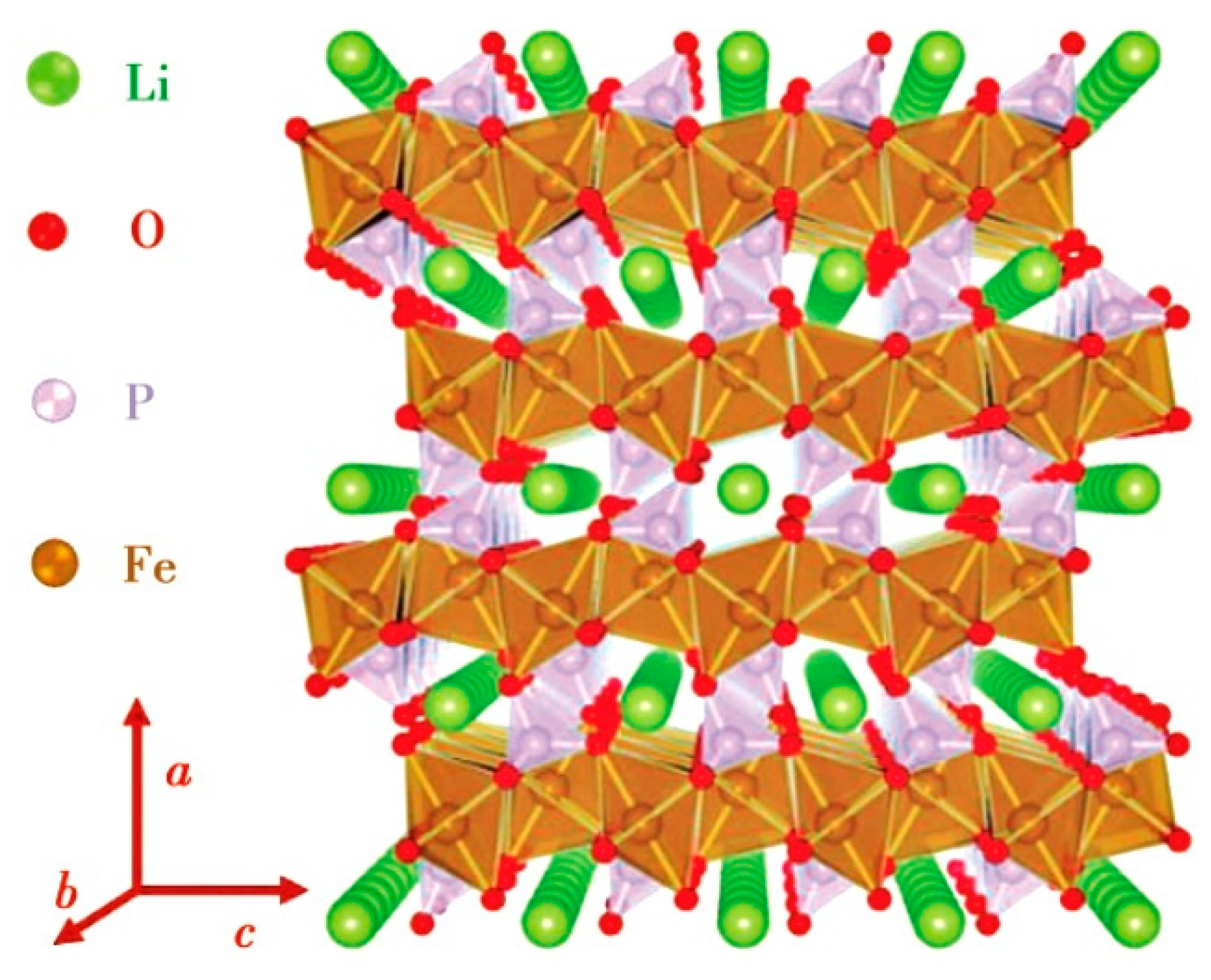
Figure 2.
Schemes of (a) core-shell and (b) mosaic models for Li+ extraction/reinsertion in LFP particles [13], (c) FP phase in the form of fine filaments during lithium removal [14], (d) FP filament changes direction when expands to another particle [14], (e) polarization of LFP particles during charging at rates of 0.1C and 2C [11].
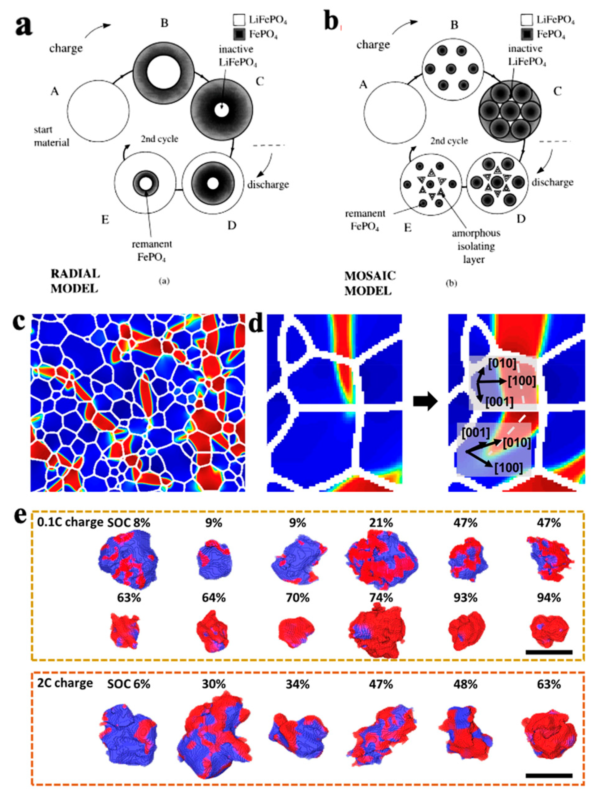
Figure 3.
Carbon coating on LFP particles. (a) SEM morphology of LiFePO4/C [9], (b) SEM morphology of LiFePO4/activated carbon/graphene [15], (c) carbon materials for LiFePO4 modification [18], (d) TEM morphology of LiFePO4/C/CNT structure [20], (e) SEM image of LiFePO4/graphite [9].

Figure 4.
Crystal structure and transition metal (TM) element doping of NCM. (a) Crystal structure of NCM [23], (b) Discharge specific capacity, thermal stability, and capacity retention of Ni, Co, and Mn transition metal doped ternary materials [24].
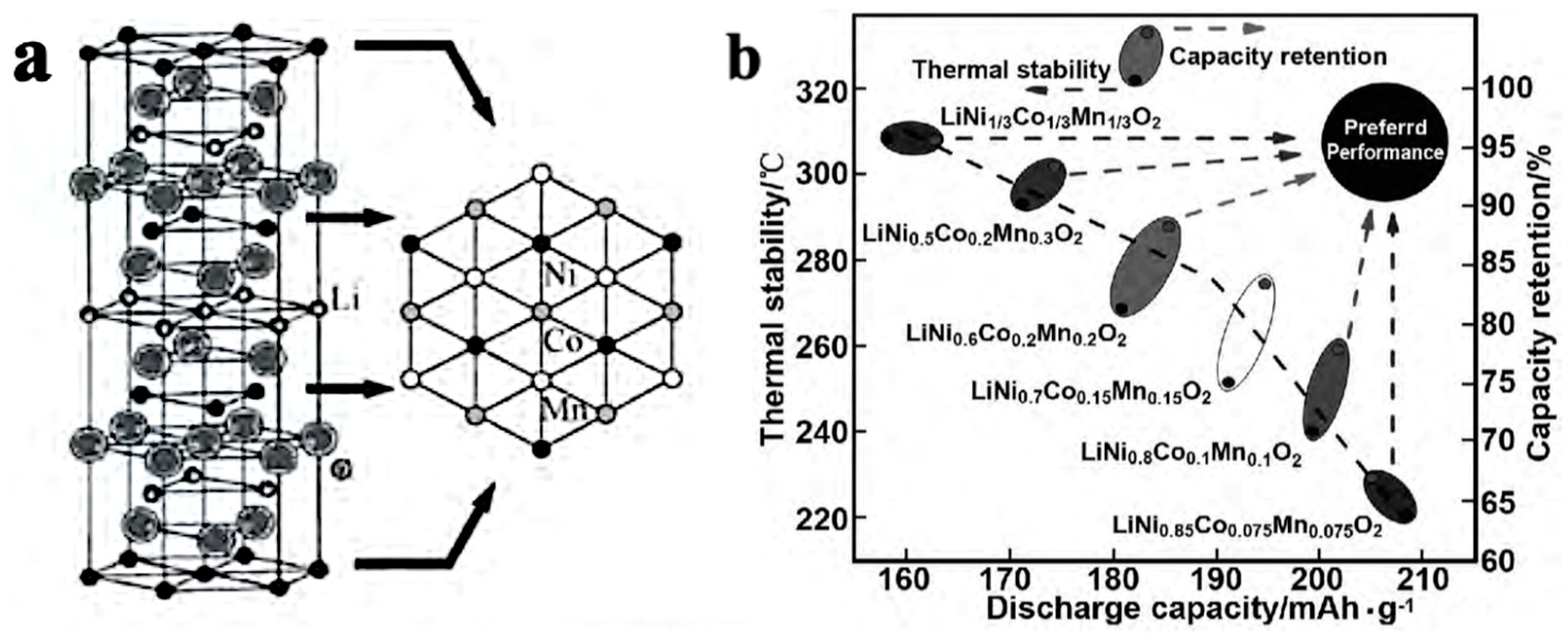
Figure 5.
Particle morphology and cracks in NCM particles. (a) SEM morphology of NCM secondary and primary particles, (b) schematic diagram of the formation of intergranular cracks caused by anisotropic strain of layered primary particles within secondary particles. The arrows indicate the c-axis direction [26].
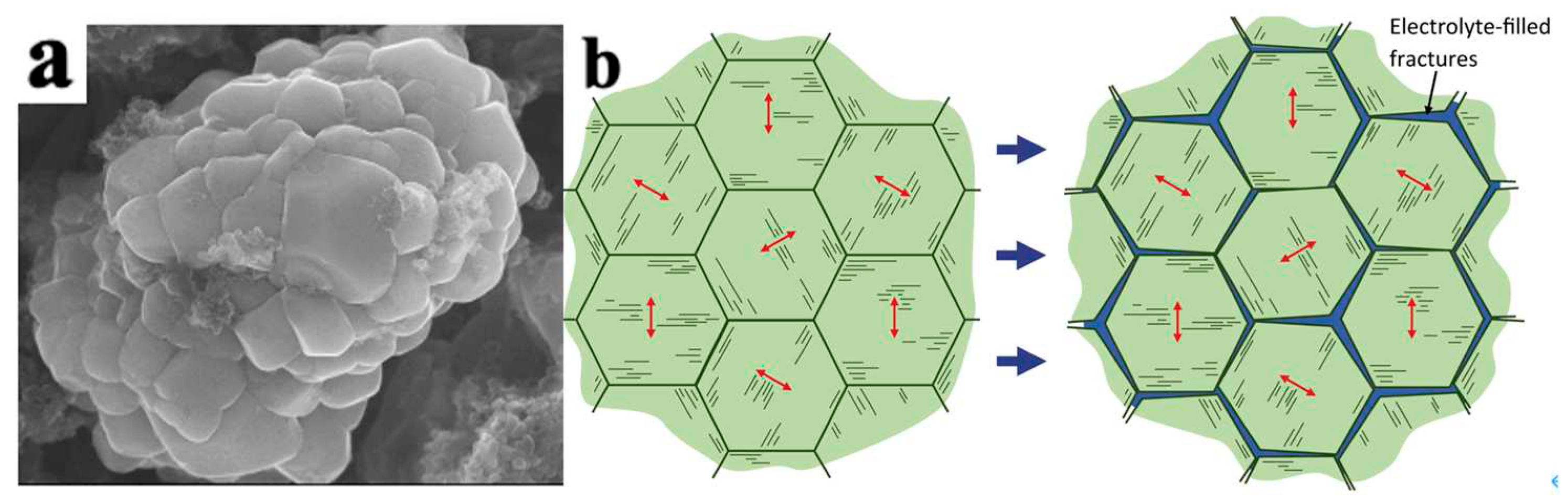
Figure 6.
Comparison of lithium ion diffusion coefficients between secondary and primary particles during charging and discharging processes [27].
Figure 6.
Comparison of lithium ion diffusion coefficients between secondary and primary particles during charging and discharging processes [27].
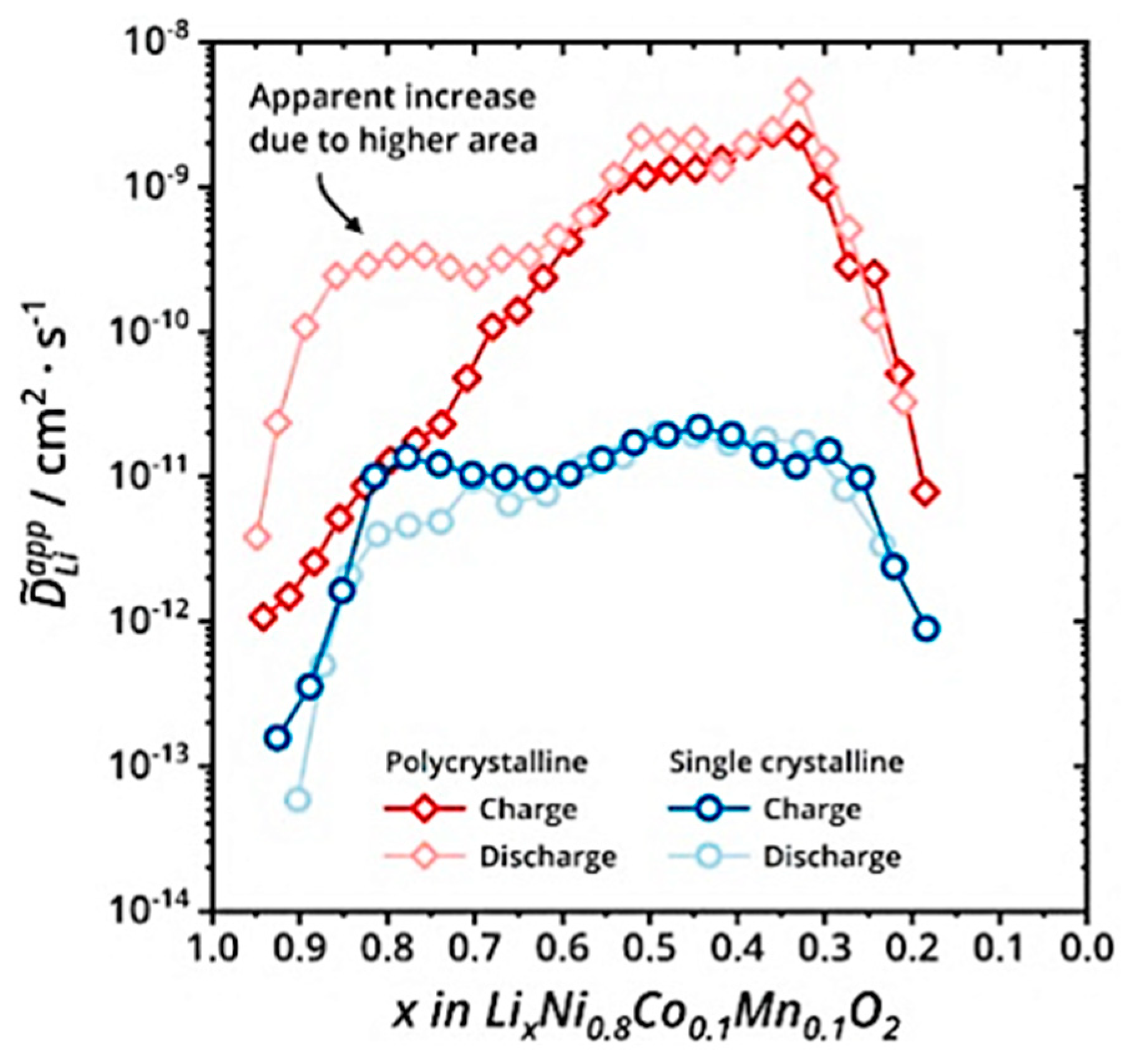
Figure 7.
Primary particle intergranular cracks and lattice change during cycling process in NCM. (a) Crack propagation morphology between NCM primary particles [29], (b) Effect of Ti-doping on the rate of lattice change in the c-axis during cyclic process [30].
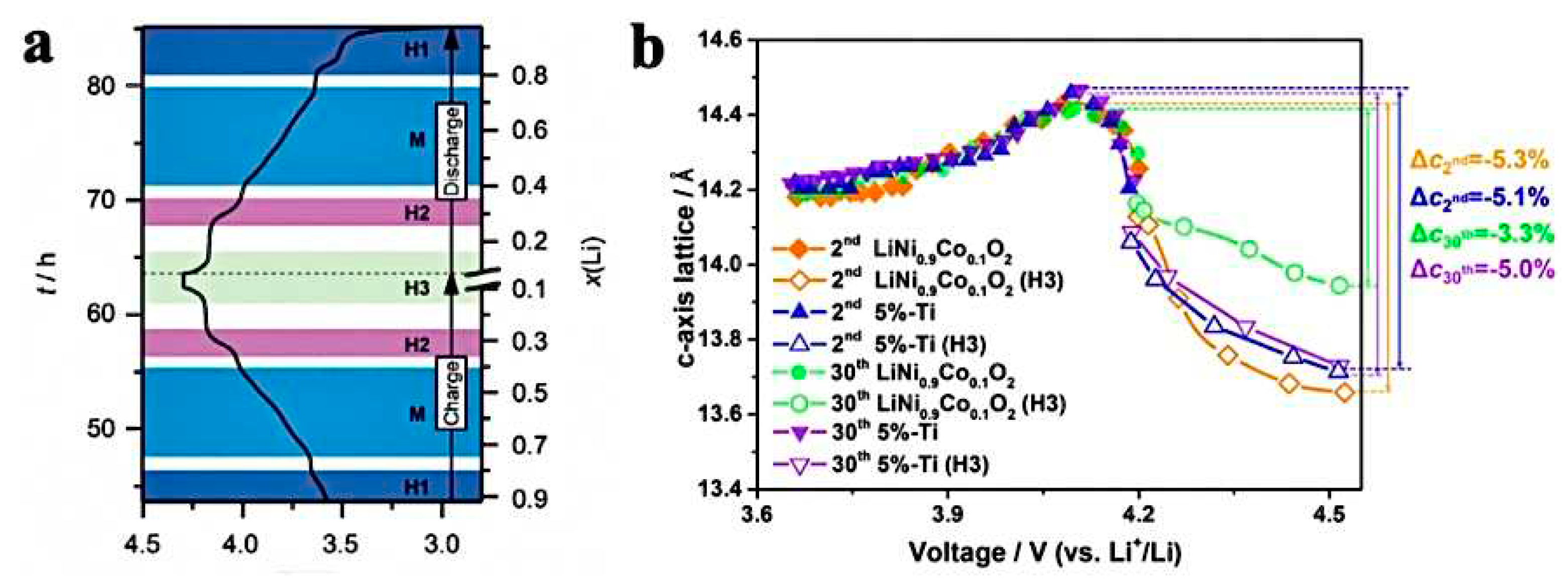
Figure 8.
Crack morphology and particle chemical phase diagram caused by NCM phase transition. (a) SEM cross-sectional crack morphology of NCM particles after 1000 cycles in the voltage range of 3.0-4.2V [35], (b) SEM cross-sectional crack morphology of NCM particles after the first cycle [36], (c) chemical phase diagrams of oxidation and reduction phases in NCM [34].


Table 1.
Comparison of common power battery parameters.
| Battery properties | Lead-acid battery [4] | Nickel metal hydride battery [5] | Lithium-ion battery | ||
|---|---|---|---|---|---|
| LFP [6] | NCM [7] | LCO [8] | |||
| Voltage (V) | 2 | 1.2 | 3.3 | 3.6 | 4.2 |
| Energy density (wh/kg) | 35-45 | 50-80 | 130-140 | 160-220 | 135-150 |
| Li+ diffusion coefficient (cm3/s) | / | / | 10-16-10-14 | 10-11-10-10 | 10-12-10-11 |
| cycle life (times) | 300-500 | 500-1000 | 2000-6000 | 1500-2000 | 500-1000 |
Table 2.
Homogeneous and island coarse coatings on cathode materials and the effects of coating modification on battery properties [43].
Table 2.
Homogeneous and island coarse coatings on cathode materials and the effects of coating modification on battery properties [43].
| Morphology | Technique | Cathode materials | Coating | Capacity (mAh·g-1)/retention rate (%) (Rate C/cycle times) |
Ref. | |
| Before coating | After coating | |||||
Homogeneous coating
|
Gas phase chemical coating | Li1.2Mn0.54Ni0.13Co0.13O2 | Al2O3 | 251-232/92.43% 0.05C/30 |
271-257/94.83% 0.05C/30 |
[44] |
| NCM523 | ZrO2 | 216-84/40% 0.03C/100 |
228-182/83.25% 0.03C/100 |
[45] | ||
| Li1.17Mn0.48Ni0.23Co0.12O2 | MgO | 240-234/97.9% 0.1C/10 |
260-258/99.55% 0.1C/10 |
[46] | ||
Island coarse coating
|
Dry coating | LiNi0.815Co0.15Al0.035O2 | Li3PO4 | 195-139/70.55% 1C/100 |
192-171/89.06% 1C/100 |
[47] |
| NCM525 | Li2MoO4 | 186-97 48% 0.2C/50 |
178-138 78% 0.2C/50 |
[48] | ||
| Wet coating | Li[Li0.05Ni0.4Co0.15Mn0.4]O2 | Al2O3 | 155-133/86% 1C/50 |
157-150.7/96% 1C/50 |
[42] | |
| NMC532 | H3PO4 | 135-44/32.59% 1C/100 |
214-189/88.32% 1C/100 |
[49] | ||
Disclaimer/Publisher’s Note: The statements, opinions and data contained in all publications are solely those of the individual author(s) and contributor(s) and not of MDPI and/or the editor(s). MDPI and/or the editor(s) disclaim responsibility for any injury to people or property resulting from any ideas, methods, instructions or products referred to in the content. |
© 2023 by the authors. Licensee MDPI, Basel, Switzerland. This article is an open access article distributed under the terms and conditions of the Creative Commons Attribution (CC BY) license (http://creativecommons.org/licenses/by/4.0/).
Copyright: This open access article is published under a Creative Commons CC BY 4.0 license, which permit the free download, distribution, and reuse, provided that the author and preprint are cited in any reuse.


