
Submitted:
28 July 2023
Posted:
01 August 2023
You are already at the latest version
Abstract
Several lime mortars for the repair of painted plasters of the rock cut church of Ss. Pietro and Paolo in Matera were studied. They were designed taking into account both aesthetic criteria that need to be fulfilled in the field of paintings restoration, and physical-mechanical compatibility with the original materials on site, i.e. the pre-existing plasters and the supporting rock. Mixes with calcareous and silica aggregates, based on different grain size proportions, were prepared for filling missing portions of the original painted plaster. The effects of the mineralogical nature and size of the aggregates on the characteristics and properties of the mixes were investigated in relation to the microstructure, physical-mechanical features and resistance to salt ageing. At the end of the experimental campaign, the overall performances were evaluated.
Keywords:
air lime mortars
; calcareous aggregate
; silica aggregate
; microstructure
; physical-mechanical performance
; salt ageing
1. Introduction
Conservation of painted plasters in Cultural Heritage deserves great attention as regard the choice of new materials to be employed. Especially for wall paintings in rupestrian settlements, specific and unique challenges for their conservation derive from the complex physical, chemical and biological interactions between the rock-cut context, the surrounding environment and the artefacts within it [1]. Well-confined underground environments generally present microclimatic stability due to their relative isolation from the outside, which inhibits those degradation processes promoted by variable thermo-hygrometric conditions [2,3,4]. Significant decay may be triggered when subterranean sites are in connection with outside and thermo-hygrometric values are affected by seasonal periods [5]. Especially salt damage may occur, due to salts conveyed in water solution, which may penetrate the plaster’s pore network [6,7]. Original plasters often show whitening caused by salt crystallization on the surface. In the most severe cases, they are affected by decohesion and scaling, as well as lifting and flaking of pictorial layers, caused by the crystallization pressures of salts growing within the material under the surface [8], and these phenomena are often observed right next to mortars applied in previous restoration works. Loss of the plaster in more or less extended areas makes grouting operations necessary to fill the lacunae. In general, the choice of repair mortars should be made taking into account the compatibility with both the substrate and the pre-existing plasters under the colored layers [9]. The compatibility between the restoration materials and the original ones, investigated under chemical-petrographic, mechanical and physical aspects, is one of the fundamental requirements for the formulation of suitable repair mortars [10,11,12]. Chemical compatibility means that restoration mortars should have similar composition as the original plaster and do not contain products that may trigger degradation processes in the pre-existing materials, such as soluble salts. Physical compatibility should ensure that new mortars do not act as a barrier to the movement of water, humidity and saline solutions, but do constitute a preferential path for their transfer to the surface. Mechanical compatibility affects the mortar reversibility and consists of having lower mechanical properties than the original plaster, so that any stresses would impact more on the grouting, as sacrificial material, than on the original plaster. Along with these necessary constraints, durability should also be considered even if a sacrificial function of the new materials should be maintained. Finally, aesthetical factors also need to be respected, according to the restoration principles and theory.
Depending on these requirements, it is clear that, when mortars for restoration are designed, particular attention should be addressed to a variety of factors having influence on the resulting performance. In primis, porosity - which is closely dependent on the components chosen for the production of a mortar, including the binder, the aggregate and the amount of water in the mix - is the characteristic that influences the physical and mechanical compatibility the most [13]. Furthermore, pore sizes determine the effects of salt crystallization and thus mortar’s durability [14]. The aggregates, as well, play a fundamental role in determining the mechanical properties of the mortar, depending on the nature, quantity and size [15,16,17,18].
Historic plasters are generally made of air lime binder. Therefore, materials at least similar in composition and properties to the original ones should be used for the restoration works, according to the recommendations of international bodies, such as ICOMOS or ICCROM [19,20]. However, reproducing historical mortars is not an easy task for several reasons. Firstly, it is difficult to exactly determine the compositional ratio, which is one of the factors that decisively influence the characteristics and the performance of air lime mortars [21]. A further limit in re-proposing mortars as similar as the historic ones is that traditional know-how in the manufacture and application of lime mortars has mostly been lost, as these mortars have been disused in building technology starting from the advent of hydraulic lime and cement, whose incompatibility with traditional materials has been well established [22,23].
In this paper we present a study, carried out during a thesis work at Istituto Centrale per il Restauro of Matera, which was aimed at designing suitable repair mortars for the conservation of wall paintings in the hypogeal crypt of Ss. Pietro and Paolo in the church of San Francesco (Figure 1), one of the most ancient sites within the UNESCO rupestrian settlement of Matera (Southern Italy). Rock-cut painted caves are important elements of the rupestrian art [24,25]. They are widespread in Southern Italy, with an impressive example in the Matera site, where large rupestrian settlements developed especially during the Middle Age [26], in the form of caves dug excavated in the soft calcarenite rock outcropping in the area [27]. These caves were often religious and devotional sites, so that their walls were decorated with painted plaster, whose unicity makes the rupestrian cultural heritage worth to be preserved as an example of the history and the cultural identity of the community.
In particular, for the conservation of the wall paintings in the crypt of St. Francesco church, air lime mortars with calcareous and silica aggregates and with different granulometric assortments were prepared. They were set in relation to the knowledge of some aspects of the original plaster and the underlying rock, but also on the basis of aesthetical restoration requirements. Microstructure features, physical-mechanical properties and resistance to salt ageing were investigated by several analyses and tests and they were evaluated for the screening of the most suitable mixes.
2. Materials and Methods
2.1. The pre-existing rock and plaster
The mediaeval crypt of Ss. Pietro and Paolo in Matera is a church excavated within a Plio-Plestocenic calcarenite (Gravina Calcarenite geological formation), locally named “calcareous tuff”. The rock has pale yellow color and is almost exclusively made of fossil remains binded by poor calcite cement (Figure 2a,b). It is a soft rock and typically has a very high (from 40 to 50%, approximately) and coarse porosity, with prevailing pore radius sizes between 10 μm and some hundreds of micrometers, which promotes high capillary water absorption, up to about 700 mg/cm2 [28,29].
The frescoes are applied on a plaster having an average thickness of 1 cm, which covers the cut rock surface. The plaster is made of air hardening lime and calcareous aggregates coming from the grinded calcarenite of the rocky bank (Figure 3a). Clasts' dimensions range from 100 to 900 μm, with an average size mostly between 200 and 400 µm. The binder:aggregate ratio estimated on thin sections was 1:1.5 by volume. The plaster shows dissolution phenomena at the expense of the calcite matrix and the presence of fissures and vugs often occluded by gypsum. The pictorial layer, with a thickness of about 200 µm, consists of earth pigments and whitewash. The porosity of the plaster, as determined by MIP, is 45 %, with prevailing pore-size radii in the range 1-8 µm (Figure 3b) [30].
2.2. Experimental materials
Two mortar types for the repair of the wall painted plasters, specific for retouchable and not-retouchable fillings of the lacunae, were designed. In the restoration field, each of these two mortars has well defined aesthetical constraints. Retouchable mortars (R) are meant to fill missing parts of the plaster up to the painted surface level [11]. They should be white, because they are destined to be painted with watercolors in order to reconstruct the missing part of the figurative pattern and have a similar texture to that of the ancient fresco, that is smooth. Not-retouchable mortars (NR) fill lacunae whose figurative reconstruction is impossible because it would imply a free interpretation of the figurative text by the restorer. In this case, grouting must be realized at a slightly lower level than the painted surface and the repair mortar is not supposed to be painted or retouched, so it should have a proper color itself, not strongly in contrast with the painting appearance, and a proper texture, irregular and coarse [11]. As reported below, aggregates with different nature (calcareous and silicate), were used for the two mortar types, to respond to these different needs.
To address, as much as possible, the requirements of physical-mechanical compatibility with the original plasters, as well as with the underlying rock, the design of the formulations was made on the basis of some features of the pre-existing plaster and its state of conservation. In particular, taking into account the high porosity of the original plaster and the calcareous rock support, the design of the mortars aimed at porous and low-strength formulations.
For both the experimental mortars, lime putty binder was used. It gives weaker mechanical strength than hydraulic lime [13]. Compared to hydrated lime powder it has better workability [31] and achieves higher porosity levels and better pore sizes assortments [32], the latter providing a lower susceptibility to salt damage.
The lime putty used (by Calceviva in Fasano, Southern Italy) is aged over 24 months. It is classified as CL90-SPL [33], mainly composed of portlandite and, secondly, of calcite (Figure 4a). The following aggregates were selected: a local grinded calcarenite (tufina, T) from Matera, with whitish - pale yellow color and composed of 98% CaCO3, approximately (Figure 4b); a grinded calcarenite (carparo, C) from the near Puglia region, warm orange coloured and composed of 80% CaCO3, approximately (Figure 4c); a river sand from Ginosa (G), near Matera (Figure 4d). T aggregate has the same provenance of the aggregate in the original plaster within the church, namely the calcarenite from the hosting rock bank belonging to the geological outcrop of Gravina calcarenite. C is a variety dating to Pleistocene of the soft and porous calcarenites outcropping in Southern Italy [29], while Ginosa sand comes from the Plio-Pleistocenic deposits in the area of Matera [34] and is mainly composed of quartz, chert, feldspars and a low amount of calcite. Mineralogical composition of T, C and G is shown in Figure 4b–d.
Considering that the pre-existing plaster has been weakened, due to the depletion of the carbonate matrix by dissolution phenomena promoted by water and due to salt action, as resulting by microscopic observations, the ratio between binder and aggregates (B:A) was chosen 1:3, namely higher than 1:1.5 of the original mortar, to have an acceptable compromise between porosity and mechanical strength. It has been demonstrated that porosity is strongly linked to the lime content: lime rich mortars, with a 1:1 binder/aggregate mortar is more porous than those with more aggregates because lime is a very porous material [17]. Being equal other factors, high lime contents, such as those corresponding to 1:1 and 1:2, also determine higher mechanical strengths than the lower B:A ratio of 1:3 [35], although this effect is not always observed, if not in the long term [21]. Indeed, a large binder content has a complex of implications with the mechanical behaviour: while it determines a higher porosity that acts on the strength reduction, in an opposite way it may improve mechanical properties as it leads to a more continuous structure, due to less voids at the interface with the aggregates, and also favours carbonation, thanks to the high air permeability [17]. On the contrary, by increasing the aggregate content, it has been found that 1:3 mortars have mechanical strength similar to those poorer in lime, such as mortars with B:A ratios of 1:4 and 1:5, despite being more porous than these ones [17,36]. Moreover, faster carbonation with less crack development in the final products has been demonstrated for long-term aged lime putty (>1 year) with B:A ratios ≤ 1:4 [35]. The ratio between binder and water was 1:3 in volume, which includes the water content in the lime putty and the water amount added during the mixing.
2.2.1. Retouchable mortars (R)
Whitish colour required for the retouchable mortars was obtained by using pale yellow aggregate of T type (Figure 5a). Starting from the clast sizes microscopically observed in the pre-existing plaster, ranging from 100 µm to 900 µm, the following granulometric fractions were considered: 125 µm < x < 250 µm; 250 µm < x <500 µm; 500 µm < x < 1mm.
Three different retouchable mortar formulations were designed by mixing different percentages of aggregate in these dimensional ranges: RF and RM corresponding to prevailing fine (50%) and medium aggregate (60%), respectively, and RC having the highest amount of coarse aggregates (40%) and the lowest one in the finest range (Table 1, Figure 6a).
2.2.2. Not-retouchable mortars (NR)
The T-type aggregate used in R mortars was not appropriate to fulfil the aesthetical restoration constraints for not retouchable mortars, because of the whitish colour that it produces. Therefore, yellow calcarenite (C-type) and river sand (G) were used for these mortars, as these aggregates were able to provide proper color and texture (Figure 5b,c). Moreover, in addition to the grain sizes adopted for the R formulations, a further dimension range from 1 to 1.4 mm was introduced, as medium-fine sand granulometries yielded a rough and vibrant mortar appearance. Several preliminary mix tests made necessary to change the proportions between the granulometric ranges implemented for R mortars and they led to the following formulations (Table 2, Figure 6b): NRF with prevailing fine to medium aggregates (80%); NRM with prevailing medium and coarse a aggregates (60%) and NRC, which is characterised by a predominance of coarse (a) and coarse (b) aggregates (80%).
2.3. Analyses and tests
Several analyses and tests were conducted to investigate mortar’s characteristics and properties.
- Mortars’ microstructure was investigated on thin sections under polarized transmitted light by optical microscopy (Eclipse LV100 Nikon);
- Porosity features were determined by Mercury Intrusion Porosimetry (MIP). Pore size distribution (pore radii in a range from 0.001 µm to 100 µm) and the integral open porosity were measured by a Pascal 140/240 Series porosimeter by Thermo Finningan (maximum injection pressure of 200 MPa). For each mortar mix, three specimens with a volume between 2 and 3 cm3 were tested. The apparent density (γa) of the specimens was also measured by MIP;
- Physical behavior under ultrasonic pulse velocity (UPV) test was investigated according to ASTM standard D2845-05 [37]. Three cubes 4x4x4 cm for each mix were used. Before the test, they were dried in an oven at 60° C until they reached a constant weight. The direct transmission method was employed, namely with the transmitter and the receiver positioned on the opposite faces of the specimens. The UPV results were expressed as the average of the measurements along the x, y, and z directions, and in each point the average of three acquisitions was considered. A Panametrics Epoch 4 Plus Ultrasonic Flaw Detector (Olympus), with a pair of ultrasonic transducers of 18 mm diameter and 1 MHz central frequency, was used for the measurements. A coupling agent (ultrasonic gel) served to improve the signal readability. The pulse velocity was calculated as the ratio of the distance between the transducers (measured by a digital caliper with a precision of 0.01 mm) and the time of flight (automatically registered by the instrument).
- Capillary water absorption test was executed on five 5x5x2 cm specimens, according to UNI EN 15801 standard [38]. The mortars’ weights were recorded up to 5 days that is when the absorption reached a constant value (successive weight variations less than 0,1%). The ratios between the weight of the absorbed water and the absorbing surface area were plotted versus the square root of time (in seconds) to obtain the corresponding curves. The total water amount (Q) absorbed by the samples and the absorption coefficient (AC) were calculated.
- Water vapor permeability test was carried out on five specimens 5x5x1 cm for each mix according to the UNI EN15803 standard [39]. The test conditions were 23°C and 50% RH. The water vapor permeability (δp) was expressed as:
δp =G x D/A x ∆pv
where G is the rate of the vapor flow, D is the specimen thickness, A is the surface of evaporation and Δpv is the water vapor pressure difference across the specimen.
The water vapor resistance coefficient (µ) was determined as:
where δa is the water vapor permeability of air.
µ=δa/δp
- Uniaxial compressive strength (UCS) and flexural strength (FS) were determined following UNI EN 1015-11 standard [40]. FS test was carried out on three specimens 4x4x16 cm for each mortar. The two resulting halves of each specimen, obtained from the bending rupture, were used for UCS test. Both tests were conducted with a Controls Model 65 testing machine equipped with 15 kN load pistons.
- Microdrilling test was also performed, to determine the resistance of the mortars to a rotating tip. Drilling resistance was measured by a DRMS (Drilling Resistance Measurement System) Cordless device (SINT Technology), equipped with a polycrystalline diamond coated flat-tip drill bit of 5 mm diameter. The drilling test was performed on one 4x4x16 cm specimen for each mortar mix. Three holes per specimen were drilled, up to a depth of 20 mm. The penetration force was recorded every 0.05 mm for a total of 200 acquisitions for each hole. The wearing of the drill was almost negligible for the soft lime mortars used in this study. The penetration rate and rotational speed were established after preliminary tests and were set at 20 mm/min and 50 rpm, respectively.
- Salt ageing test. There is still no commonly accepted procedure for mortar salt ageing [41,42]. The test was performed following RILEM MSA2 recommendation [43] with some modifications, such as a lower concentration of the saline solution to reproduce more realistic conditions. Cubic specimens with sides of 4 cm were dried in an oven at 60 °C and then sealed on the lateral surfaces by using Parafilm stripes in order to convey the evaporation flow only along the z-direction. Then, they were immersed 10 mm high from their base for 2 hours in a 3% sodium sulphate solution, which reproduces more realistic conditions compared to higher salt concentrations [44]. After the absorption of the saline solution, they were dried on a plastic tray for 22 hours at 20 °C and 50% RH in a CH250 CLIMATEST ARGOLAB climatic chamber, after which salts formed on the surface and they were removed by brush. Daily cycles were repeated over 12 weeks (84 days). After each cycle visual observations and weight measurements were carried out, and a graph of the weight variations as a function of time was elaborated.
3. Results and discussions
3.1. Mortars’ microstructure and porosity features
As illustrated in Table 3 and Figure 7 and Figure 8, different mortars microstructures and porosity features, depending on the nature and sizes of the aggregates, were detected for the studied formulations. The accessible porosities measured by MIP (Table 3) show very close values among samples of each of the two R (from 36 to 39%) and NR groups (from 33 to 35%), but higher for the former. Apparent density values were higher for NR than R formulations.
Pore size distribution (Figure 7a) shows that mortars of the R group have pore radii mainly between 0.0025 and 15 μm, with a bimodal trend. In particular, RF and RM have the main peak in the range from 4 up to 6 μm and a second one between 0.1 and 0.2 μm. RC shows the main peak between 0.05 and 0.1 μm. Compared to RM and RF, it has a lower pore volume in the 2-8 μm range and a higher one from 8 up to 20 μm, with a second peak centered between 10 and 15 μm.
NR formulations also have bimodal patterns (Figure 7b). They have very similar distributions under pore sizes of 4 μm, where the main size peak for each of them is between 0.05 and 0.2 μm. Over 4 μm, it can be observed that NRF has a high pore concentration in the range of 10-20 µm while the maximum peak for NRM and NRC is set between 25 and 50 μm.
Finest pores, generally with radii lower than 1 μm are those forming in the lime paste [45,46]. Their presence was found irrespective of nature and grain sizes of the aggregates in both R and NR mortar formulations. As reported in Table 3, the relative volumes of pores under 1μm in the two mortar types are similar, namely between 32 % and 36 % in R mortars, unless RM mix (40%), and between 33% and 36% in NR ones.
Bigger pores starting from some microns’ size arise from the voids at the interface between the binder and the aggregates, entrapped air-voids in the mix, as well as shrinkage fissures originating within the paste during drying [16,32,47].
Comparing the distributions of these pores in R and NR mortars, the former shows a higher amount in the range between 1 and <10 µm (from 37 to 58 %) than NR mixes (from 14 to 20 %). The latter have large pores in the range between ≥10 and 100 µm varying from 42 and 49%, while in the R mortars these pores have notably lower percentages from 8 to 27%.
Passing from the formulations with prevailing fine grain sizes to those with prevailing coarse aggregates, an increase of the pore volume with radii in the range from 10 to100 μm was recorded, at the expense of pores between 1 and 10 μm (Table 3). This finding was recorded for both mortar types, suggesting that the fine aggregate more homogeneously mixes with the binder, thus limiting the formation of larger fissures due to the shrinkage.
According to porosimetric results, the microscopic characteristics of the mortars (Figure 7a,b) evidence that R samples contain notably less coarse pores due to shrinkage (from 10 to 100 μm radii) than NR. On the contrary, especially NRM and NRC show a lot of large and ultra-large pores from some tens to some hundreds of micrometers in size, respectively. These ultra-large pores fall out of the upper limit of measurement by MIP.
This occurrence has to be taken into account in evaluating the integral open porosity results from MIP analysis (Table 3). As commented before, MIP porosity values in R samples were found slightly higher (from 36 to 39%) than in NR samples (from 33 to 35%). Such porosity values do not include voids over 100 μm radii, which can be widely observed microscopically in NR mortars, so it is evident that porosity measured by MIP in the latter is underestimated and the corresponding values of apparent density result higher than those recorded for R mortars.
The notably different microstructures resulting for R and NR mortars, despite the same binder-aggregate ratio and mixing water, can be attributed to the nature of the aggregate. Indeed, in R mixtures, the aggregate is exclusively calcareous, while in NR mortars, only 20% is calcareous and the remaining 80% is silicate. The calcareous aggregate comes from a rock having a high open porosity (between 40% and 50%), including both intergranular and intragranular voids [29,48], part of which especially at the intragranular level are probably maintained in the grinded fraction. The porosity of the aggregate, being able to absorb the mixing water, could account for lower coarse shrinkage fissures observed in R mixtures. Conversely, such a type of contribution cannot be expected by the silicate aggregates, mainly composed of single quartz and chert grains or tightened poly-minerals fragments having an almost absent porosity. It is a fact that in R mortars, the porosity resolved microscopically, which is of both inter-granular and intra-granular types, mainly ranges from some micrometers to only a few tens of micrometers, and only sometimes ultra-large shrinkage pores were observed.
In addition, widespread discontinuities were found in NR samples along the silicate grains at the contact with the binder. The coarser the aggregate, the more extended these fissures along the grains, so that larger pores increase passing from formulations with prevailing fine grain sizes to coarser ones. The lower volume of large pores observed in R mortars compared to NR ones can be attributed to the higher cohesion between the matrix and the calcareous aggregates, due to their chemical affinity: this leads to a reduction in the content of the discontinuities between the lime and the aggregate [49]. According to the literature, the presence of calcareous aggregates in aerial lime mortars results in a better quality of the interfacial transition zone between the aggregate and the matrix [50]. During the carbonation of the lime, the calcite of the aggregates provides nucleating sites for the crystal growth of calcite in the paste, favoring compositional continuity and good adhesion between the aggregate and the matrix [16,17]. Moreover, porous calcareous aggregate, as having an absorbent surface, may be impregnated by the binder, thus creating a strong bond between the two mortar components, which also increase mortar resistance [15].
Finally, on the basis of the porosimetric and microscopic analyses, we can state that all the experimental mortars possess accessible porosity values comparable to those of the pre-existing materials and this finding lets to expect a compatible use with the very porous painted plaster and the underlying rock. Moreover, by comparing the porosimetric distributions of new mortars and original one (Table 3), it results that both R and NR mortars have higher pore sizes assortments that, in principle, may ensure balanced physical performance as regards the compatibility.
3.2. Behavior in water transfer
Mean capillary absorption curves are reported in Figure 9a,b, while the coefficient of water absorption by capillarity (AC) and the total amount of water absorbed per unit area (Q) are reported in Table 4.
All the samples very quickly absorbed water by capillarity during the early steps (Figure 9a,b). In particular, the water uptake for R samples was about 90% of the total amount in the first 20’; for NR mortars this percentage was reached after only 5’ for NRM and NRC, and after 10’ for NRF.
AC values of the three R formulations were very close. NR mortars showed higher values of AC (from 22 to 34 mg/cm2s-1/2). In this case, the mortar with prevailing fine aggregates (NRF) had a lower absorption rate.
At the end of the test, namely after 5 days, the total amounts of water absorbed were comparable for both R and NR mortars.
On the basis of the obtained results, it can be concluded that both types of mortars ensure high water transfer typical of very porous materials and comparable with the hydric properties of the excavated rock of the church site. The higher kinetics of absorption recorded in NR mortars come from the higher presence of coarse pores, which very effectively contribute to the capillary uptake [51,52]. It seems that in R mortars, which are particularly rich in pores between 1 and 10 microns, the rate of absorption promoted by these pores is less effective compared to the larger ones.
Passing from prevailing coarse grain sizes to fine-graded mortars formulations, coarse porosity decreases, so it is also evident an effect of the aggregate sizes of both calcareous and silicate type in reducing the kinetics of the water uptake. Finally, a contribution of the lime putty binder on the high water absorption has also to be taken into account, according to the literature, which reports higher absorption efficiency of the microstructure in mortars with lime putty compared to mortars with aerial lime [53,54].
The results of the water vapor permeability test (Table 4) show that vapor resistance values of both R and NR formulations are not so diversified.
Unless the slightly higher values of the water vapor diffusion resistance coefficient (μ) near 10 for the formulations with prevailing medium sized aggregates (RM and NRM), all the other mortar mixes have μ coefficient values of less than 10. According to literature [55,56], values of μ <10 are suitable for rendering and repair mortars, while standards [57,58] report higher acceptable values of μ ≤ 15 and μ ≤ 12, respectively.
3.3. UPVs and mechanical properties
As reported in Table 5, ultrasonic investigations show that R mortars generally have higher propagation velocities (from 1482 to 1386 m/s) compared to the NR ones (from 1180 to 947 m/s). The lowest velocities were recorded in the mixes with prevailing coarser aggregates for both mortar types.
In a similar vein, higher compressive strengths were measured for R type. There is a good correlation (coefficient of correlation = 0.89) between the ultrasonic velocities and the compressive strengths (Figure 10), as higher mechanical strengths correspond to higher ultrasonic velocities.
These results have correlations with the materials’ microstructural features. Lower UPVs and UCSs in NR mortars likely depend on the higher porosity and pore sizes, as evaluated by both MIP and optical microscopy. The progressive increase of large and ultra-large pores passing from mortars with prevailing fine aggregates to mortars with coarser ones explains why the lowest velocities were found for the NRC mix.
Better bonding between the calcareous aggregate and the lime matrix, with consequent lower porosities and void sizes in R formulations, account for the higher propagation velocities of ultrasonic waves and higher compressive strengths, as well. Also, in these mortars the ultrasonic velocities are influenced by the granulometric assortment of the aggregates, as mortars with fine aggregates have a more homogenous and uniform structure, with fewer largest voids than mortars made of coarse ones, and this results in higher velocity values.
The bending strength test showed significant differences between the formulations of R and NR groups, with quite lower resistance in the latter (Table 5). These results are relevant to the lower quality of the interfacial transition zone, due to diffuse discontinuities between the silica aggregates and the carbonate binder, to a greater extent the coarser the grains. Indeed, the difference among FSs were negligible for R formulations, while they were more evident within the NR group.
Compressive and flexural strengths for both N and NR indicate good mechanical performance within the range reported in literature for air hardening lime mortars for restoration [17,59] and close to the quite high values reported by [21,32,60] and suggest a positive contribution of the lime putty to the mechanical properties of the investigated mortars [21,54].
The presence of silicate aggregates in the NR formulations also results in lower strengths under the microdrilling test (Table 5). Results show that R mortars, unless RC formulation, show higher mean drilling resistance than NR mortars. The strength measured for RC mix is less than half of the values measured for RF and RM mixes. This behavior could be an effect of the coarse grains, which lead to formation of larger chips and consequent lower forces recorded. As for the NR mortars, no differences were observed in the values of the mean drilling resistance among the three formulations, due to a prevailing effect of the discontinuities between the grains, which cause a larger propagation of the cracked zone and the formation of larger fragments during drilling [61].
3.4. Resistance to salt ageing
After salt ageing, all R and RM samples showed evident material losses at the evaporation surface (Figure 11).
Weekly normalized mean weights for R samples (Figure 12) show an increase after the first two weeks, due to the salt accumulation within the porous structure. Starting from the third week, weight decreases were observed, meaning that loss of materials due to mortar decohesion, as an effect of salt damage, prevailed on the salt accumulation. It is worthy to note that for NR samples weight decreases took place earlier, namely starting from the second week.
At the end of the test, that is after 12 weeks, R mortars showed lower losses of material than NR ones.
It is well known that material’s susceptibility to salt crystallization pressures depends on pore dimensions, as the tension caused by the growth of the salt crystals is greater in small than in large pores and can overcome tensile strength, causing the breakage of pore walls [62,63]. Despite higher concentrations of large and ultra-large pores, which could let to expect a lower susceptibility to salt damage, NR mortars behave worse than R and this result once again can be attributed to the higher cohesion of the latter, which comes from the better adhesion between the grains and the lime binder. Indeed, textural characteristics play an important role on the incidence of the salt damage in grain framework materials’ types [64,65]. The weight losses were recorded similar for mortars having fine and coarse prevailing aggregates in each of the two groups, while the weight decrease was recorded slightly lower for mortar samples with prevailing medium-grained aggregates, suggesting that in these cases a better grading of the grains may have led to a better compaction and voids filling by the lime.
4. Conclusions
Lime mortars with calcareous and silica aggregates (R and NR types, respectively) and with different grain size proportions, for the repair of painted plasters in the rock-cut church of SS. Pietro and Paolo in Matera, were studied.
The study shows that from a physical point of view all the formulations analyzed are compatible with the characteristics of the pre-existing materials of the paintings. Both mortar types resulted in high porosity values, comparable with those of both the highly porous rock and original plaster. MIP analyses detected pore percentages between 32 and 40%, which were likely underestimated considering the presence of ultra-large pores, detected by microscopic analysis but out of the range of porosimetric measurement. Ultra-large porosity was especially observed in mortars with silica aggregates. The behavior of the porous system in relation to water showed that all the mixes, regardless of the grain sizes proportions, guarantee the transfer of water in the liquid and gaseous phase that easily can infiltrate through the rock bank in hypogeal conditions. This means that the new mortars would not create a barrier to migration of water moving from inside the rock bank to the surface of the painted mortar. On the contrary repair mortars will act as permeable fillers, avoiding the accumulation of water and subsequent damages on the expense of the surrounding original plaster.
Mortars microstructures were found to be different among the formulations. The presence of large pores (between 10 and 100 μm) and ultra-large pores with sizes of some hundreds of micrometres was found typically high in the NR mortars, whose composition was made by a prevalence of silica aggregate. As microscopically observed, the ultra-large pores come from fissures along the contact surface of the aggregate grains with the calcite matrix, due to a diffuse lack of adhesion between them, as well as from a higher shrinkage. On the contrary, R mortars, namely those with calcareous aggregate, had lower pore sizes, mainly between 1 and 10 μm, because of the affinity between the binder and the calcareous grains, which results in a better adhesion of these components and a lower shrinkage as well, probably because porous calcareous rock fragments are more able than non-porous silica grains to absorb the mixing water.
In both types of mortars (R and NR), the effect of the aggregate size, passing from formulations with prevailing fine aggregates to formulations with prevailing coarse grains, led to an increment in pore size. The rate of the water uptake increased as well, indicating the high effectiveness of coarse pores in capillary absorption, while mechanical strengths decreased.
The study pointed out that the different microstructures also affected the behavior of the mortar in relation to ultrasonic wave propagation velocities and they reflected in higher compressive and flexural strengths for mortars with calcareous aggregate (R type) compared to those with silica aggregate (NR type). Resistance to the microdrill test also confirmed this trend. The measured mechanical properties typically denote low-strength mortars, able to ensure a sacrificial function in repair works. The use of lime putty binder seems to provide good mechanical quality levels within the performance variability of air hardening lime mortars, confirming that traditional materials deserve attention in the current mortar’s technology in order to obtain suitable materials to be used in the restoration field.
The two mortar types also exhibited different salt weathering resistance. In this regard, the study shows that the textural features of the mortars played a major role than the pore dimensions. Despite the presence of large and ultra-large pores, which would lead to expect lower susceptibility to salt damage, under salt ageing test the mortars with silica aggregate had earlier and higher damage by decohesion than R mortars. The better quality of the interface between calcareous grains and lime binder makes the latter more able to contrast the pressures developed within the pores by the salts’ crystal growth.
Finally, the overall results showed that mortar formulations of both types having prevailing medium-sized aggregates, had the best performance in terms of mechanical strengths and resistance to salt damage and this result was due also to the better grading of the aggregate.
The present research is a first step of a larger study. After the application in the crypt, the selected mortars will be monitored on site over time in order to detect any changes in the optical and morphological properties of the repair mortars and the surrounding wall painted surfaces, in order to verify possible interactions over time between the new plasters and the original materials of the artefact, as well as the durability of the new mortars themselves.
Author Contributions
Conceptualization, F.E.C., M.G., S.M., M.C.G., A.C. and S.I.; methodology, F.E.C., M.G., S.M., M.C.G. and A.C.; validation, A.C., G.Q. and S.I.; formal analysis, F.E.C., M.G., S.M., A.C. and G.Q.; investigation, F.E.C., M.G., S.M., A.C., G.Q. and D.M.; resources, A.C., G.Q. and S.I.; data curation, F.E.C., M.G., S.M., G.Q. and A.C..; writing—original draft preparation, F.E.C., M.G., S.M., S.I. and A.C.; writing—review and editing, F.E.C., M.G., S.M., A.C., G.Q. and S.I.; visualization, F.E.C., M.G., S.M., and A.C.; supervision, A.C.; project administration, M.C.G. and A.C.; All authors have read and agreed to the published version of the manuscript.
Funding
Microdrilling test was conducted at the FIXLAB node of the European Research Infrastructure (E-RIHS) located at CNR-ISPC in Lecce, Italy. The laboratory has been granted by MUR through the SHINE (Strengthening the Italian Node of E-RIHS) Project (PIR0 1_00016, PON IR 2014-2020).
Acknowledgments
The authors want to thank Dr. Emilia Vasanelli at ISPC-CNR, in Lecce, for her support to the UPV measurements and microdrilling test.
References
- Mazzei, B.; Preservation and use of the religious sites: the case study of the roman catacombs. JST 2015, 11, 33–43.
- Scatigno, C.; Gaudenzi, S.; Sammartino, M.; Visco, G. A microclimate study on hypogea environments of ancient roman building. Sci. Total. Environ. 2016, 566-567, 298–305. [CrossRef]
- Sánchez Moral, S.; Cuezva, S.; García Antón, E.; Fernández Cortés, A.; Elez, J.; Benavente, D.; Cañaveras, J. C.; Jurado, V.; Rogerio Candelera, M. A.; Sáiz-Jiménez, C. Microclimatic monitoring in Altamira Cave: Two decades of scientific projects for its conservation, in The Conservation of Subterranean Cultural Heritage, CRC Press, 2014, 139–144. [CrossRef]
- Herráez, I.; Rodriguez, M.; de Alvaro, E. The conservation of the Cueva de Altamira. Stud. Conserv. 1994, 39, 80–84. [CrossRef]
- Agnew, N.; Maekawa, S.; Wei, S. Causes and Mechanisms of Deterioration and Damage in Cave 85. In Conservation of Ancient Sites on the Silk Road, Proceedings of the Second International Conference on the Conservation of Grotto Sites, Mogao Grottoes, Dunhuang, China, June 28 - July 3, 2004.
- Germinario, L.; Oguchi, C.T. Underground salt weathering of heritage stone: lithological and environmental constraints on the formation of sulfate efflorescences and crusts. J. Cult. Heritage 2021, 49, 85–93. [CrossRef]
- Pender, R.J. The behaviour of water in porous building materials and structures. Stud. Conserv. 2004, 49, 49–62. [CrossRef]
- Price, C.; Brimblecombe, P. Preventing salt damage in porous materials. Stud. Conserv. 1994, 39, 90–93. [CrossRef]
- Peroni, S.; Tersigni, G.; Torraca, G.; Cerea, S.; Forti, M.; Guidobaldi, F.; Rossi Doria, P.; De Rege, A.; Picchi, D.; Pietrafitta, F.J.; Benedetti, G. Lime based mortars for the repair of ancient masonry and possible substitutes, Proceedings of the Symposium Mortars, Cements and Grouts Used in the Conservation of Historic Buildings, Rome, Italy, 3-6 November 1981, ICCROM, Rome, Italy, 1982, 63–99.
- Isebaert, A.; Van Parys, L.; Cnudde, V. Composition and compatibility requirements of mineral repair mortars for stone – A review. Constr. Build. Mater. 2014, 59, 39–50. [CrossRef]
- Mora, P.; Mora, L.; Philipphot, P. La conservation des peintures murales, ICCROM, Editrice compositori, Bologna, 1977.
- Schueremans, L.; Cizer, Ö.; Janssens, E.; Serré, G.; Van Balen, K. Characterization of repair mortars for the assessment of their compatibility in restoration projects: Research and practice. Constr Build Mater 2011, 25, 4338–4350. [CrossRef]
- Schäfer, J.; Hilsdorf, H.K. Ancient and new lime mortars- the correlation between their composition, structure and properties. In Conservation of stone and other materials Vol. 2: Prevention and treatments. Proceedings of the International RILEM / UNESCO Congress Conservation of Stone and Other Materials: Research, Industry, Media, Held at UNESCO Headquarters, Paris, France, June 29-July 1, 1993, Ed.: M.-J. Thiel., Spon Press, London, UK, 1993, 605–612.
- Torraca, G. Porous Building Materials: materials science for architectural conservation, ICCROM, Rome, Italy, 1981, pp.149.
- Lawrence, M.; Walker, P.; D'Ayala, D. Non-Hydraulic Lime Mortars. J. Arch. Conserv. 2006, 12, 7–33. [CrossRef]
- Arizzi, A.; Cultrone, G. The influence of aggregate texture, morphology and grading on the carbonation of non-hydraulic (aerial) lime-based mortars. Q. J. Eng. Geol. Hydrogeol. 2013, 46, 507–520. [CrossRef]
- Lanas, J.; Alvarez, J. I. Masonry repair lime-based mortars: factors affecting the mechanical behavior. Cem. Concr. Res. 2003, 33, 1867–1876. [CrossRef]
- Lea, F. M. The Chemistry of Cement and Concrete, 3rd ed.; Butterworth-Heinemann, London, 1970, p. 896.
- Venice Charter, International Charter for the conservation and restoration of monuments and sites, Venice, 1964, http://www. icomos.org/docs/venice_charter.html.
- Conclusions of the Symposium Mortars, cements and grouts used in the conservation of historic buildings, ICCROM, Rome, 3-6 November 1981, Mater. Struct. 1990, 23, 235.
- Veiga, R. Air lime mortars: What else do we need to know to apply them in conservation and rehabilitation interventions? A review. Constr. Build. Mater. 2017, 157, 132–140. [CrossRef]
- Goncalves, T.D.; Rodrigues, J.D.; Abreu, M.M.; Esteves, A.M.; Silva Santos, A. Causes of salt decay and repair of plasters and renders of five historic buildings in Portugal. 2006, (Eds.), Proceedings of Heritage, Weathering and Conservation, Madrid, Spain, Gomez-Heras & C.V. 273-284.
- Hughes J.; Valek J. Mortars in historical buildings. A review of the conservation, technicaland scientific literature. Historic Scotland: Edinburgh, 2003, pp.80.
- Pelosi, C.; Agresti, G.; Andaloro, M.; Baraldi, P.; Pogliani, P.; Santamaria, U. The rock hewn wall paintings in Cappadocia (Turkey). Characterization of the constituent materials and a chronological overview, E Pre. Sci. 2013, 10, 99-108.
- Pelosi,C.;Agresti,G.;Andaloro,M.;Baraldi,P.;Pogliani,P.;Santamaria,U.;LaRussa,M.F.,Ruffolo,S.A.;Rovella N., Micro-Raman and micro-stratigraphic analysis of the painting materials in the rock-hewn church of the Forty Martyrs in Şahinefendi, Cappadocia (Turkey), Archaeometry 2016, 58, 4, 659-672. [CrossRef]
- Fonseca C.D., Civiltà delle grotte: Mezzogiorno rupestre, Edizioni del Sole, Napoli, Italy, 1988, pp. 372.
- Andriani, G.; Walsh, N. Physical properties and textural parameters of calcarenitic rocks: qualitative and quantitative evaluations. Eng. Geol. 2002, 67, 5–15. [CrossRef]
- Andriani, G.; Walsh, N. Fabric, porosity and water permeability of calcarenites from Apulia (SE Italy) used as building and ornamental stone. Bull. Eng. Geol. Environ. 2003, 62, 77–84. [CrossRef]
- Calia, A.; Lettieri, M.; Mecchi, A.; Quarta, G. The role of the petrophysical characteristics on the durability and conservation of some porous calcarenites from Southern Italy. Geol. Soc. London, Spéc. Publ. 2015, 416, 183–201. [CrossRef]
- Capasso, F.E.; Giandomenico, M.; Muca, S. Il restauro dei dipinti murali della cripta rupestre dei Ss. Pietro e Paolo a Matera. Studio sperimentale sulle stuccature e sui leganti della reintegrazione pittorica per gli ambienti ipogei, Master Thesis Istituto Centrale per il Restauro, Rome, 2021.
- Navrátilová, E.; Tihlaříková, E.; Neděla, V., Rovnaníková, P.; Pavlìk, J. Effect of the preparation of lime putties on their properties. Sci Rep 2017,7, 17260. [CrossRef]
- Aggelakopoulou, E.; Bakolas, A.; Moropoulou, A. Lime putty versus hydrated lime powder: Physicochemical and mechanical characteristics of lime based mortars. Constr. Build. Mater. 2019, 225, 633–641. [CrossRef]
- UNI EN 459-1:2010. Building lime - Part 1: Definitions, specifications and conformity criteria, UNI, Milan, 2011.
- Boenzi, F.; Radina, B.; Ricchetti, G.; Valduga, A. Note illustrative della carta geologica d’Italia 1:100.000, foglio 201 Matera, Servizio Geologico d’Italia, Nuova Tecnica Grafica, Roma, 1971.
- Cazalla, O.; Rodriguez-Navarro, C.; Sebastian, E.; Cultrone, G.; Torre, M.J. Aging of Lime Putty: Effects on Traditional Lime Mortar Carbonation. J. Am. Ceram. Soc. 2004, 83, 1070–1076. [CrossRef]
- Lanas, J.; Bernal, J.P.; Bello, M.; Alvarez, J. Mechanical properties of masonry repair dolomitic lime-based mortars. Cem. Concr. Res. 2006, 36, 951–960. [CrossRef]
- ASTM D2845-08. Standard test method for laboratory determination of pulse velocities and ultrasonic elastic constants of rock, 2008.
- UNI EN 1580:2010. Conservation of cultural property - Test methods – Determination of water absorption by capillarity. UNI, Milan, 2010.
- UNI EN15803:2010. Conservation of cultural property - Test methods - Determination of water vapour permeability, UNI, Milan, 2012.
- UNI EN 1015-11:2019. Methods of test for mortar for masonry - Part 11: Determination of flexural and compressive strength of hardened mortar, UNI, Milan, 2019.
- Lubelli, B.; Cnudde, V.; Diaz-Goncalves, T.; Franzoni, E.; Van Hees, R.P.J.; Ioannou, V.; Menendez, B.; Nunes, C.; Siedel, H.; Stefanidou, M.; Verges-Belmin, V.; Viles, H. Towards a more effective and reliable salt crystallisation test for porous building materials: state of the art. Mater. Struct. 2018, 51, 55. [CrossRef]
- Arizzi, A.; Viles, H.; Cultrone, G. Experimental testing of the durability of lime-based mortars used for rendering historic buildings. Constr. Build. Mater. 2012, 28, 807–818. [CrossRef]
- RILEM TC 127-MS: Tests for Masonry Materials and Structures, MS-A.2 Uni-directional salt crystallization test for masonry units. Mater. Struct. 1998, 31, 10-15.
- Lubelli, B.; Van Hees, R.P.J.; Nijland., T.G. Salt crystallization damage: how realistic are existing ageing tests?, AMS '14 Proceedings of the Int. Conference on Ageing of Materials & Structures Delft 26 – 28 May 2014, The Netherlands.
- Pinto, A.F.; da Fonseca, B.S.; Silva, D.V. The role of aggregate and binder content in the physical and mechanical properties of mortars from historical rubble stone masonry walls of the National Palace of Sintra. Constr. Build. Mater. 2020, 268, 121080. [CrossRef]
- Arandigoyen, M.; Bernal, J.P.; López, M.B.; Alvarez, J. Lime-pastes with different kneading water: Pore structure and capillary porosity. Appl. Surf. Sci. 2005, 252, 1449–1459. [CrossRef]
- Lawrence, R.M.; Mays, T.J.; Rigby, S.P.; Walker, P.; D'Ayala, D. Effects of carbonation on the pore structure of non-hydraulic lime mortars. Cem. Concr. Res. 2007, 37, 1059–1069. [CrossRef]
- Andriani, G.F.; Walsh, N. Petrophysical and mechanical properties of soft and porous building rocks used in Apulian monuments (south Italy). Geol. Soc. London, Spéc. Publ. 2010, 333, 129–141. [CrossRef]
- Santos, A.R.; Veiga, M.D.R.; Silva, A.S.; de Brito, J.; Álvarez, J.I. Evolution of the microstructure of lime based mortars and influence on the mechanical behaviour: The role of the aggregates. Constr. Build. Mater. 2018, 187, 907–922. [CrossRef]
- Fragata, A.; Veiga, R. Air Lime Mortars: The Influence of Calcareous Aggregate and Filler Addition. Mater. Sci. Forum 2010, 636-637, 1280–1285. [CrossRef]
- Ioannou, I.; Andreou, A.; Tsikouras, B.; Hatzipanagiotou, K. Application of the Sharp Front Model to capillary absorption in a vuggy limestone. Eng. Geol. 2009, 105, 20–23. [CrossRef]
- García-Del-Cura, M..; Benavente, D.; Martínez-Martínez, J.; Cueto, N. Sedimentary structures and physical properties of travertine and carbonate tufa building stone. Constr. Build. Mater. 2012, 28, 456–467. [CrossRef]
- Faria, P.; Henriques, F.; Rato, V. Comparative evaluation of lime mortars for architectural conservation. J. Cult. Heritage 2008, 9, 338–346. [CrossRef]
- Branco, F.C.; Belgas, M.D.; Mendes, C.; Pereira, L.; Ortega, J.M. Mechanical Performance of Lime Mortar Coatings for Rehabilitation of Masonry Elements in Old and Historical Buildings. Sustainability 2021, 13, 3281. [CrossRef]
- Veiga, M.D.R.; Fragata, A.; Velosa, A.L.; Magalhães, A.C.; Margalha, G. Lime-Based Mortars: Viability for Use as Substitution Renders in Historical Buildings. Int. J. Arch. Heritage 2010, 4, 177–195. [CrossRef]
- Bianco, N.; Calia, A.; Denotarpietro, G.; Negro, P. Hydraulic mortar and problems related to the suitability for restoration. Period. Mineral. 2013, 82, 529–542. [CrossRef]
- UNI EN 998-1:2016. Specification for mortar for masonry - Part 1: Rendering and plastering mortar, UNI, Milan, 2017.
- WTA Merkblatt 2-9-04/D Sanierputzsysteme (2004). Wissenschaftlich-Technischen Arbeitsgemeinschaft für Bauwerkserhaltung und Denkmalpflege.
- Velosa, A. L.; Rocha, F.; Veiga, M. R. Influence of chemical and mineralogical composition of metakaolin on mortar characteristics. Acta Geodyn. et Geomater. 2009, 6, 1, 121-126.
- Válek, J.; Matas, T. Experimental Study of Hot Mixed Mortars in Comparison with Lime Putty and Hydrate Mortars. In, Historic Mortars. RILEM Bookseries, 7, Springer, Dordrecht, 2012, 269 – 281.
- Vasanelli, E.; Calia, A.; Masieri, M.; Quarta, G. New insights into the use of drilling test for the characterization of soft lime mortars. Constr. Build. Mater. 2021, 316, 125894. [CrossRef]
- Scherer, G.W. Stress from crystallization of salt. Cem. Concr. Res. 2004, 34, 1613–1624. [CrossRef]
- Espinosa, R. M.; Franke, L.; Deckelmann, G. Model for themechanical stress due to the salt crystallization in porous materials. Constr. Build. Mater. 2008, 22, 1350-1367. [CrossRef]
- Alves, C.; Figueiredo, C.; Maurício, A.; Aires-Barros, L. Susceptibility of Limestone Petrographic Features to Salt Weathering: A Scanning Electron Microscopy Study. Microsc. Microanal. 2013, 19, 1231–1240. [CrossRef]
- Calia, A.; Mecchi, A.M.; Colangiuli, D.; Baccelle, L.S. Conservation issues with calcarenites used as historical building materials in Syracuse (Southern Italy). Q. J. Eng. Geol. Hydrogeol. 2013, 46, 485–492. [CrossRef]
Figure 1.
One of the wall paintings preserved in the Ss. Pietro and Paolo rock-cut crypt, representing the Madonna and Child Enthroned and two Archangels.
Figure 1.
One of the wall paintings preserved in the Ss. Pietro and Paolo rock-cut crypt, representing the Madonna and Child Enthroned and two Archangels.
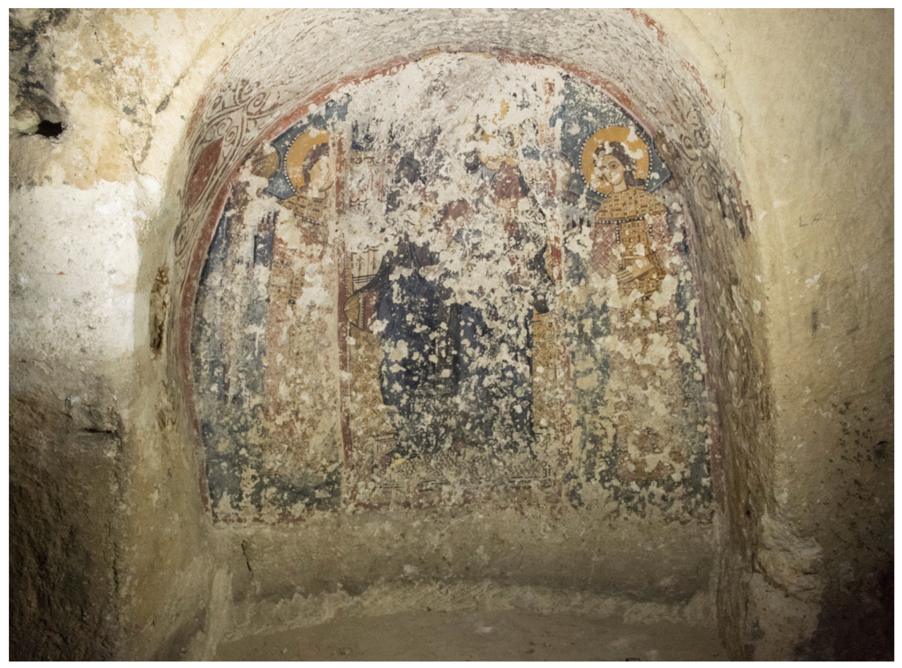
Figure 2.
(a) Macroscopic appearance of the calcarenitic cut rock; (b) thin section micrograph under polarized light and cross nicols of the same cut rock.
Figure 2.
(a) Macroscopic appearance of the calcarenitic cut rock; (b) thin section micrograph under polarized light and cross nicols of the same cut rock.
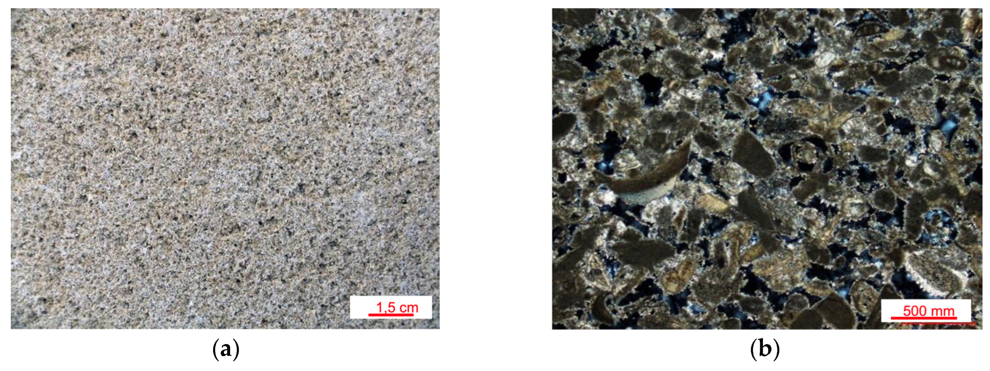
Figure 3.
(a) Thin section micrograph under polarized light and cross nicols; (b) porosimetric distribution of the original plaster.
Figure 3.
(a) Thin section micrograph under polarized light and cross nicols; (b) porosimetric distribution of the original plaster.
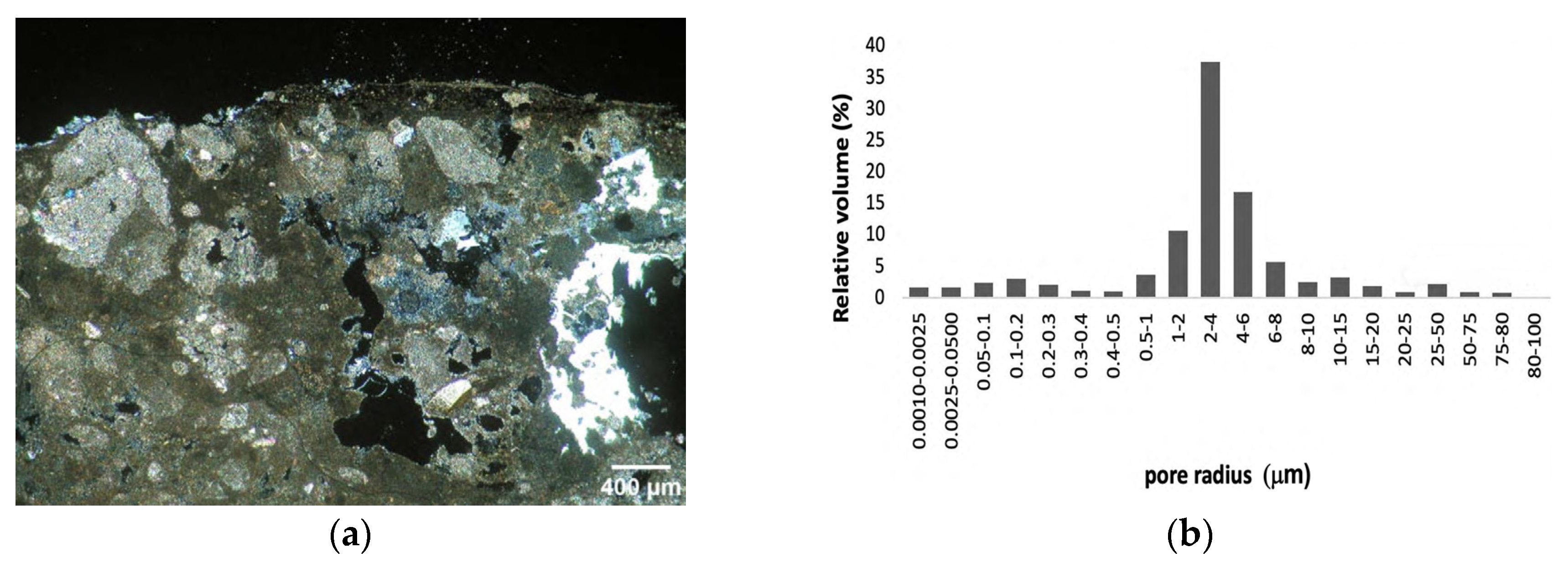
Figure 4.
XRD spectra of: (a) lime putty; (b) whitish “tufina” aggregate (T); (c) orange colored calcarenite aggregate (C); (d) river sand (G). (C: Calcite; P: Portlandite; Q: Quartz; F: Feldspar).
Figure 4.
XRD spectra of: (a) lime putty; (b) whitish “tufina” aggregate (T); (c) orange colored calcarenite aggregate (C); (d) river sand (G). (C: Calcite; P: Portlandite; Q: Quartz; F: Feldspar).
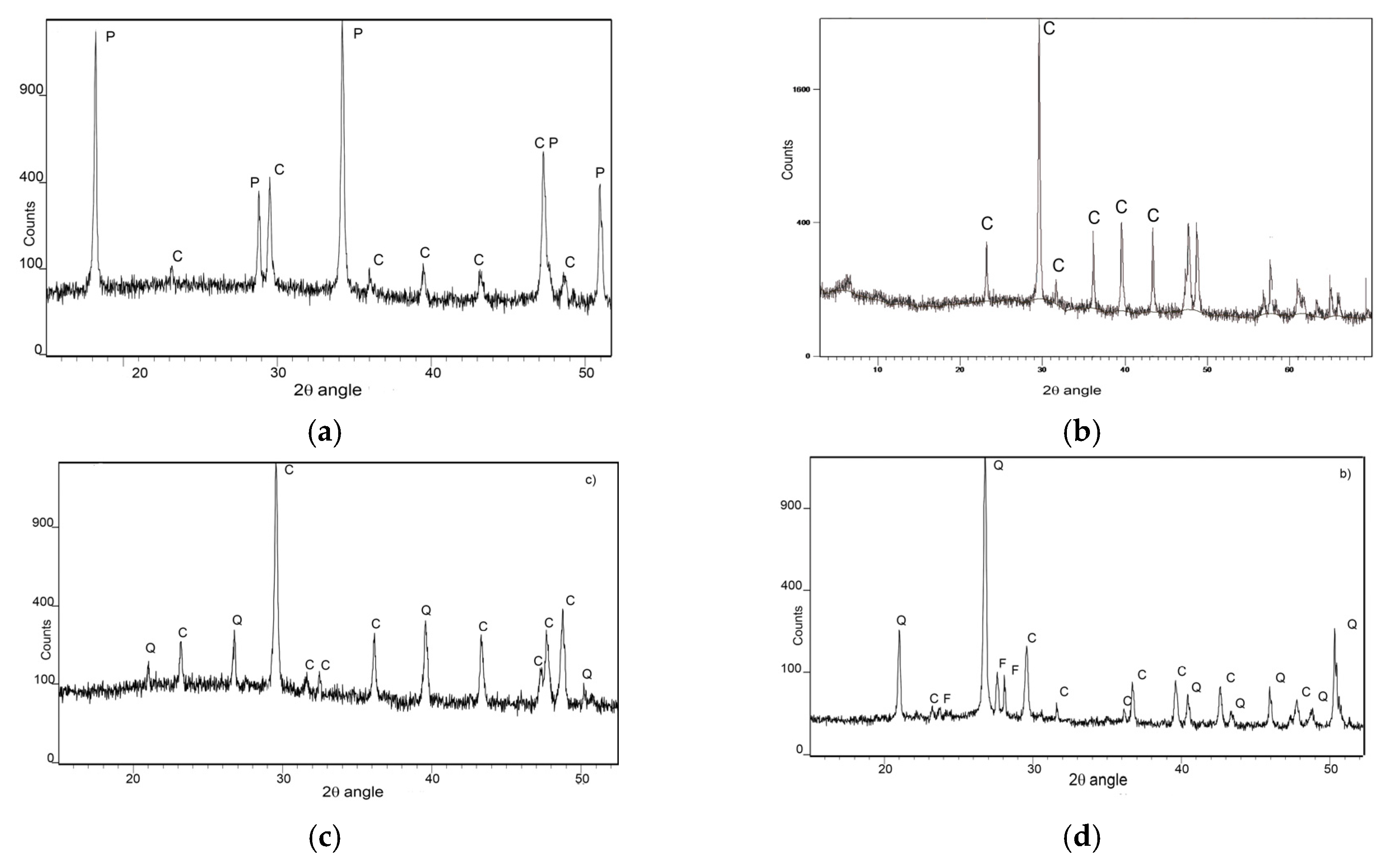
Figure 5.
T, G and C aggregates (a, b and c, respectively); R and NR representative mortar samples (d and e, respectively).
Figure 5.
T, G and C aggregates (a, b and c, respectively); R and NR representative mortar samples (d and e, respectively).
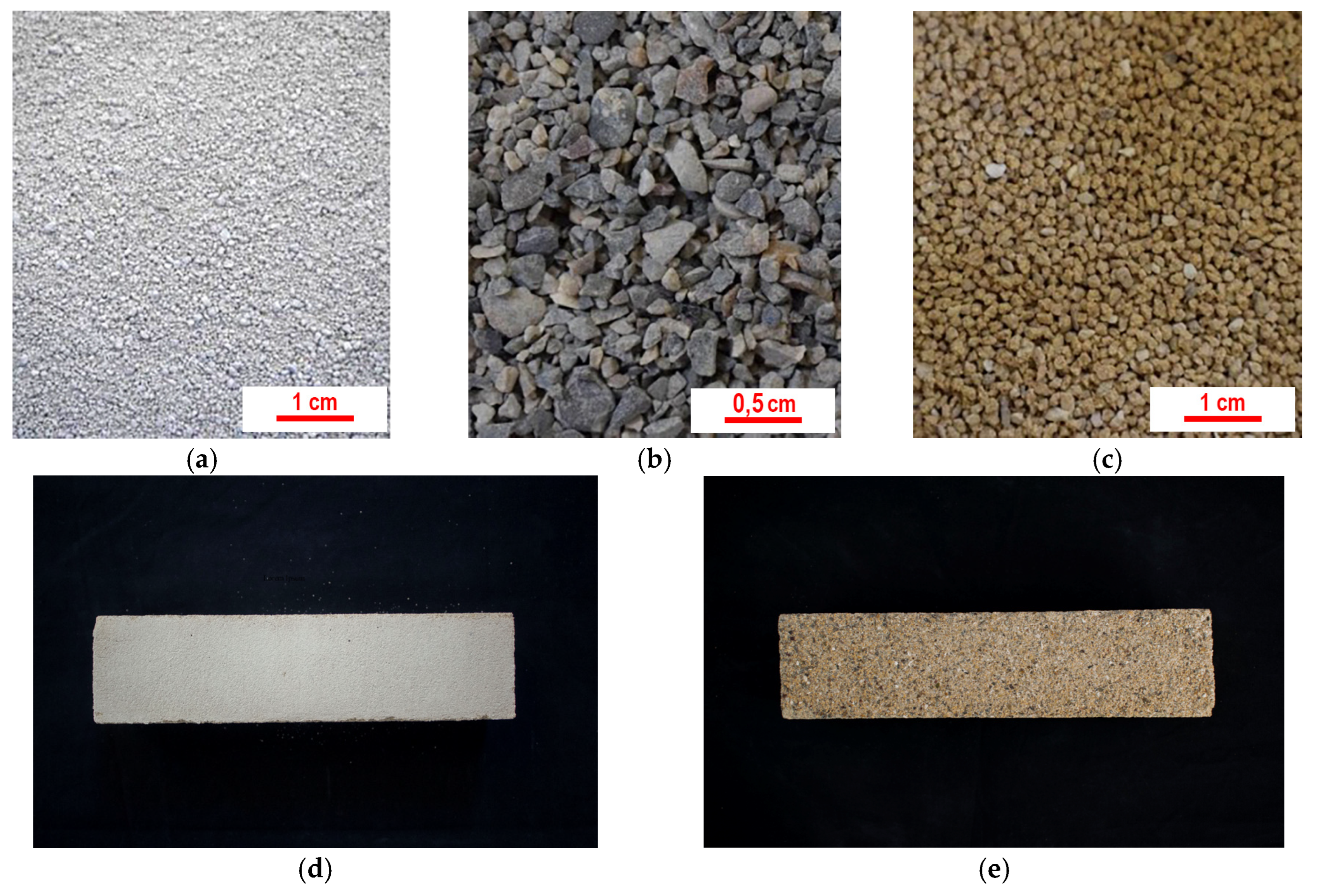
Figure 6.
Granulometric curves for the aggregates in (a) retouchable mortars; (b) not retouchable mortars.
Figure 6.
Granulometric curves for the aggregates in (a) retouchable mortars; (b) not retouchable mortars.

Figure 7.
(a) Porosimetric distribution of R mixtures; (b) Porosimetric distribution of NR mixtures.
Figure 7.
(a) Porosimetric distribution of R mixtures; (b) Porosimetric distribution of NR mixtures.
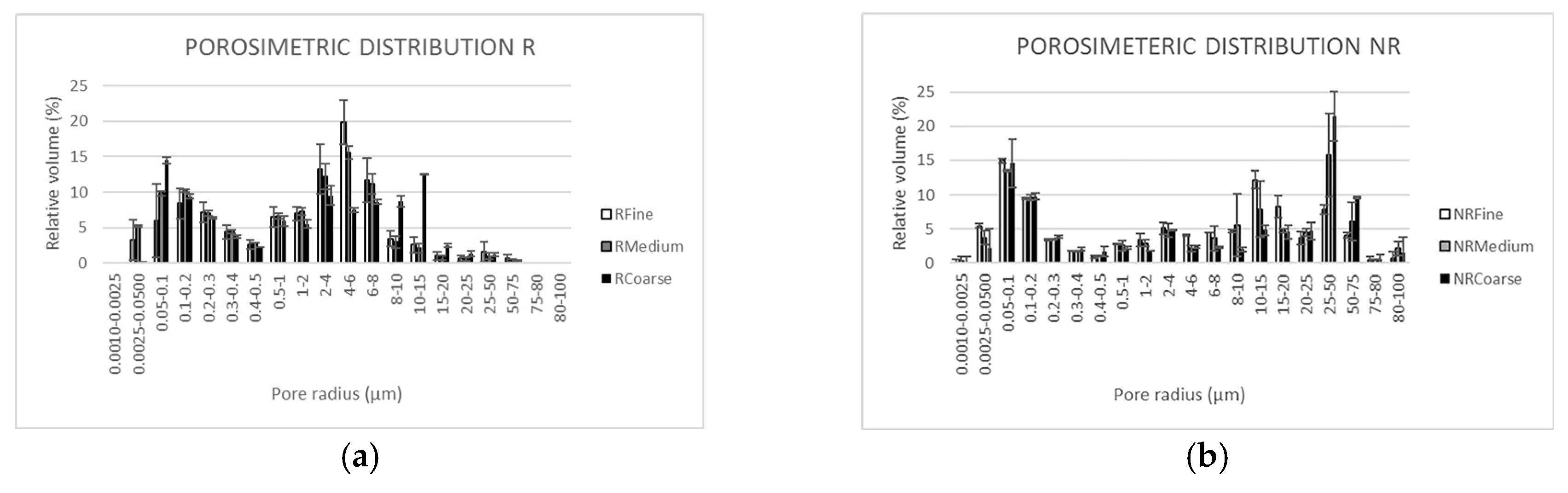
Figure 8.
Mortars’microstructures as observed on thin section under polarized light, cross nicols: (a) RF; (b) RM; (c) RC; (d) NRF; (e) NRM; (f) NRC.
Figure 8.
Mortars’microstructures as observed on thin section under polarized light, cross nicols: (a) RF; (b) RM; (c) RC; (d) NRF; (e) NRM; (f) NRC.
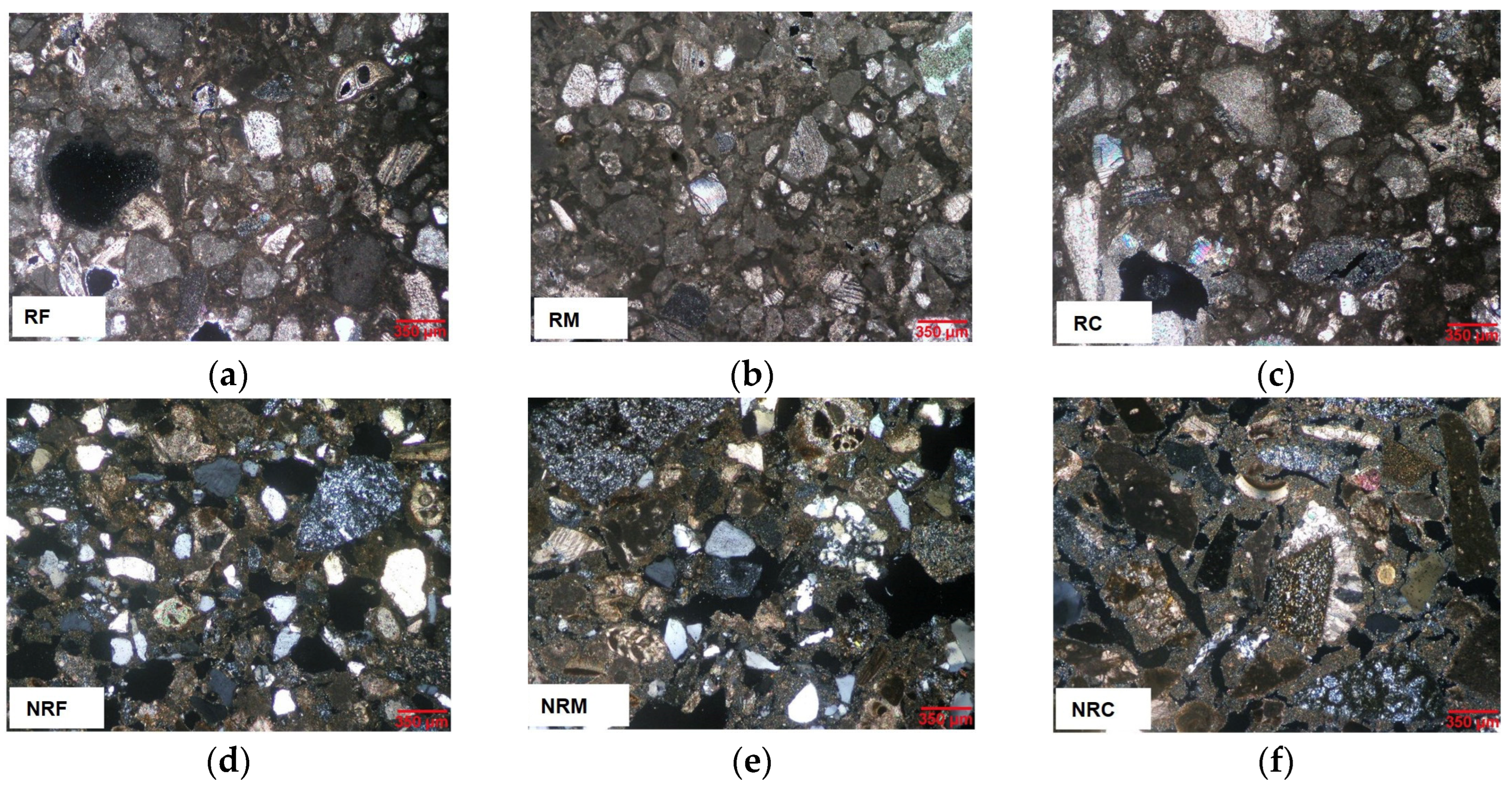
Figure 9.
Capillary water absorption as a function of square root of time for each formulation of (a) R type; (b) NR type.
Figure 9.
Capillary water absorption as a function of square root of time for each formulation of (a) R type; (b) NR type.
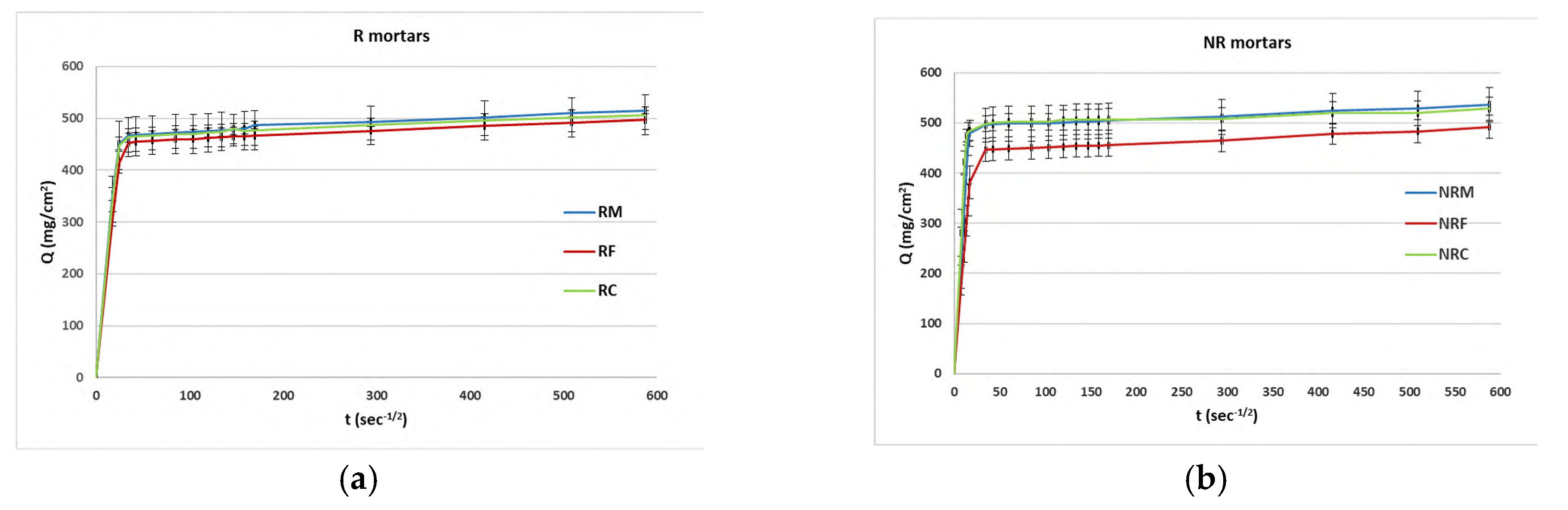
Figure 10.
Correlation between UCS and UPV for R and NR formulations.
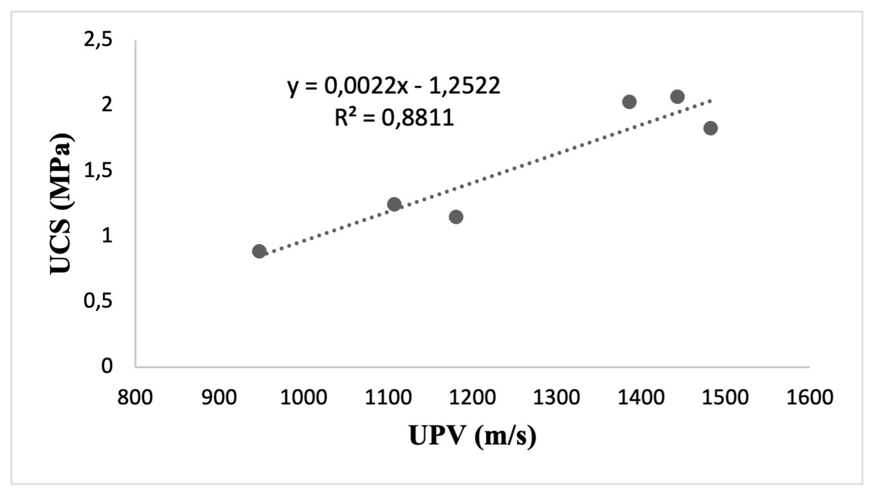
Figure 11.
Macroscopic damage observed after salt ageing on representative samples of each R and RM formulation.
Figure 11.
Macroscopic damage observed after salt ageing on representative samples of each R and RM formulation.
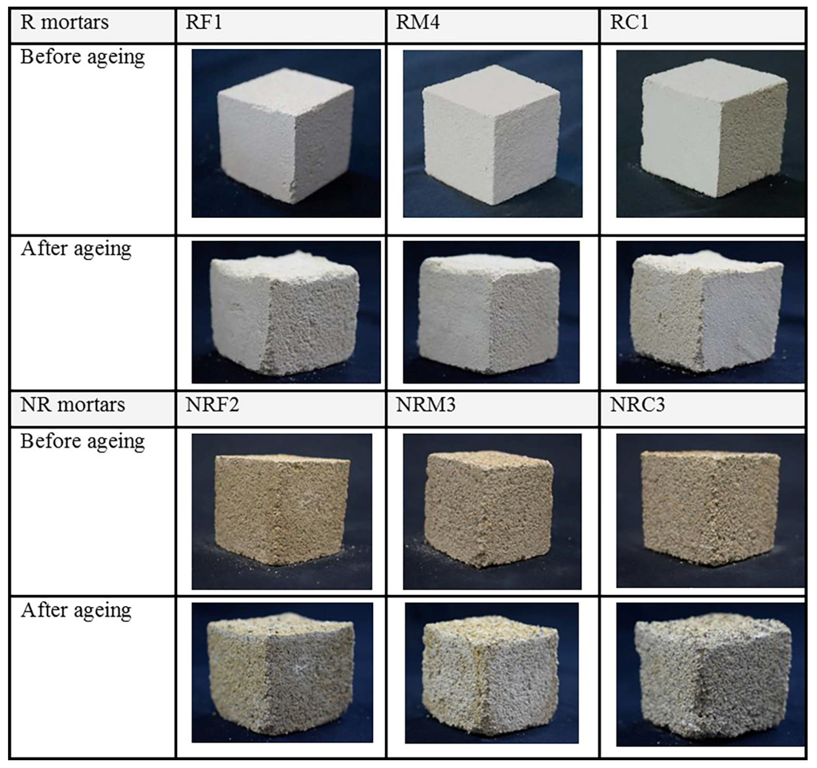
Figure 12.
Weekly mean normalized weights for R and NR samples during salt ageing.
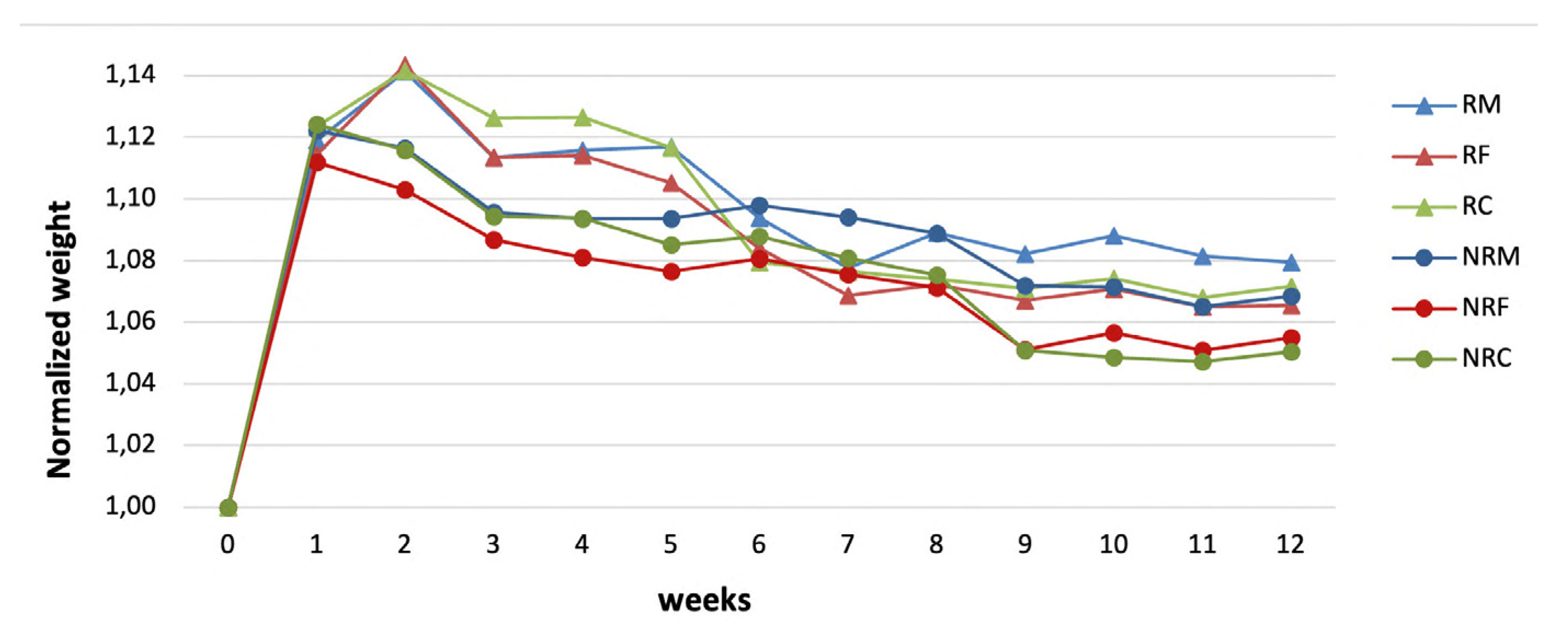

Table 1.
Aggregate size percentages for R mortars: RF (Fine), RM (Medium) and RC (Coarse).
| Aggregate size | RF | RM | RC |
|---|---|---|---|
| Aggregate amount (%) | |||
| Coarse (a): 500 µm - 1mm | 10 | 20 | 40 |
| Medium: 250 µm - 500 µm | 40 | 60 | 50 |
| Fine: 125 µm - 250 µm | 50 | 20 | 10 |
Table 2.
Type, grain size and percentage amounts of aggregates in not-retouchable mortars: NRF (Fine), NRM (Medium) and NRC (Coarse).
Table 2.
Type, grain size and percentage amounts of aggregates in not-retouchable mortars: NRF (Fine), NRM (Medium) and NRC (Coarse).
| Aggregate size | NRF | NRM | NRC | ||||||
|---|---|---|---|---|---|---|---|---|---|
| Aggregate type and amounts (%) | |||||||||
| C | G | (C+G) | C | G | (C+G) | C | G | (C+G) | |
| Coarse (b): 1 mm - 1,4 mm | - | 10 | 10 | - | 20 | 20 | 10 | 20 | 30 |
| Coarse (a): 500 µm - 1mm | - | 10 | 10 | 20 | 10 | 30 | - | 50 | 50 |
| Medium: 250 µm - 500 µm | 20 | 20 | 40 | - | 30 | 30 | 20 | - | 20 |
| Fine: 125 µm - 250 µm | - | 40 | 40 | - | 20 | 20 | - | - | - |
Samples of both mortar types, with different dimensions depending on the tests, were prepared in casts. Then they underwent 90 days of curing in laboratory conditions (20°C and 60% RH).
Table 3.
Apparent density, open porosity values and relative volume of pores grouped in three main size ranges, along with standard deviations, for each R and NR mortar mix.
Table 3.
Apparent density, open porosity values and relative volume of pores grouped in three main size ranges, along with standard deviations, for each R and NR mortar mix.
| Mix | Apparent density (g/cm3) |
Porosity (%) |
Pore volume (%) |
||
|---|---|---|---|---|---|
| 0.01- <1 µm | ≥1 - <10 µm | ≥10-100 µm | |||
| RF | 1.75 ± 0.02 | 38,8±1.7 | 32 | 58 | 10 |
| RM | 1.69 ± 0.01 | 36.2±0.1 | 40 | 53 | 8 |
| RC | 1.72 ± 0.04 | 38±0.6 | 36 | 37 | 27 |
| NRF | 1.85 ± 0.01 | 33,2±0.3 | 36 | 20 | 42 |
| NRM | 1.82 ± 0.06 | 34,7±0.8 | 33 | 16 | 47 |
| NRC | 1.81 ±0.02 | 33.6±0.3 | 34 | 14 | 49 |
| original plaster | 1,66±0.01 | 45,5±0,5 | 13 | 74 | 13 |
Table 4.
Mean values of absorption coefficient (AC), amounts of absorbed water by capillarity per unit area (Q) and water vapor diffusion resistance coefficient (µ) along with standard deviations for each mix of R and NR group.
Table 4.
Mean values of absorption coefficient (AC), amounts of absorbed water by capillarity per unit area (Q) and water vapor diffusion resistance coefficient (µ) along with standard deviations for each mix of R and NR group.
| Mix | AC (mg/cm2s-1/2) |
Q (mg/cm2) |
µ |
|---|---|---|---|
| RF | 17±1 | 497±18 | 8,5±0,4 |
| RM | 19±1 | 515±6 | 9,6±0,4 |
| RC | 19±2 | 523±12 | 8,9±1,0 |
| NRF | 22±2 | 492±23 | 7,9±0,7 |
| NRM | 31±3 | 535±34 | 10,1±0,5 |
| NRC | 34±7 | 523±25 | 8,7±0,9 |
Table 5.
Ultrasonic pulse velocity (UPV), bending strength (FS), compressive strength (UCS) and drilling resistance (DR) mean values with corresponding standard deviations for R and NR mixtures.
Table 5.
Ultrasonic pulse velocity (UPV), bending strength (FS), compressive strength (UCS) and drilling resistance (DR) mean values with corresponding standard deviations for R and NR mixtures.
| MIX | UPV (m/s) |
FS (MPa) |
UCS (MPa) |
DR mean (N) |
|---|---|---|---|---|
| RF | 1482±79 | 1,82±0,18 | 1,83±0,28 | 4,51±0,37 |
| RM | 1442±75 | 2,01±0,08 | 2,07±0,16 | 4,77±0,22 |
| RC | 1386±52 | 1,81±0,26 | 2,03±0,19 | 2,09±0,98 |
| NRF | 1180±53 | 0,74±0,11 | 1,10±0,05 | 2,58±0,51 |
| NRM | 1106±80 | 0,68±0,06 | 1,25±0,19 | 2,55±0,38 |
| NRC | 947±68 | 0,48±0,18 | 0,89±0,09 | 2,66±0,35 |
Disclaimer/Publisher’s Note: The statements, opinions and data contained in all publications are solely those of the individual author(s) and contributor(s) and not of MDPI and/or the editor(s). MDPI and/or the editor(s) disclaim responsibility for any injury to people or property resulting from any ideas, methods, instructions or products referred to in the content. |
© 2023 by the authors. Licensee MDPI, Basel, Switzerland. This article is an open access article distributed under the terms and conditions of the Creative Commons Attribution (CC BY) license (http://creativecommons.org/licenses/by/4.0/).
Copyright: This open access article is published under a Creative Commons CC BY 4.0 license, which permit the free download, distribution, and reuse, provided that the author and preprint are cited in any reuse.


